EP3015248B1 - Method and device for reforming plastic pre-forms with cross-sectional change of a volume flow - Google Patents
Method and device for reforming plastic pre-forms with cross-sectional change of a volume flow Download PDFInfo
- Publication number
- EP3015248B1 EP3015248B1 EP15191985.9A EP15191985A EP3015248B1 EP 3015248 B1 EP3015248 B1 EP 3015248B1 EP 15191985 A EP15191985 A EP 15191985A EP 3015248 B1 EP3015248 B1 EP 3015248B1
- Authority
- EP
- European Patent Office
- Prior art keywords
- pressure
- fluid medium
- plastic preforms
- blowing
- compressed air
- Prior art date
- Legal status (The legal status is an assumption and is not a legal conclusion. Google has not performed a legal analysis and makes no representation as to the accuracy of the status listed.)
- Active
Links
- 238000000034 method Methods 0.000 title claims description 60
- 230000008859 change Effects 0.000 title description 5
- 238000002407 reforming Methods 0.000 title 1
- 238000007664 blowing Methods 0.000 claims description 57
- 239000012530 fluid Substances 0.000 claims description 15
- 230000002093 peripheral effect Effects 0.000 claims description 2
- 238000007493 shaping process Methods 0.000 claims 2
- 238000005259 measurement Methods 0.000 claims 1
- 239000003570 air Substances 0.000 description 89
- 230000008569 process Effects 0.000 description 25
- 230000009969 flowable effect Effects 0.000 description 17
- 238000004064 recycling Methods 0.000 description 10
- 230000009466 transformation Effects 0.000 description 7
- 238000000071 blow moulding Methods 0.000 description 6
- 238000013022 venting Methods 0.000 description 6
- 238000006243 chemical reaction Methods 0.000 description 5
- 238000009826 distribution Methods 0.000 description 5
- 230000006870 function Effects 0.000 description 5
- 239000000463 material Substances 0.000 description 5
- 230000004048 modification Effects 0.000 description 5
- 238000012986 modification Methods 0.000 description 5
- 238000010438 heat treatment Methods 0.000 description 4
- 238000004519 manufacturing process Methods 0.000 description 3
- 230000008901 benefit Effects 0.000 description 2
- 230000001419 dependent effect Effects 0.000 description 2
- 238000011161 development Methods 0.000 description 2
- 230000018109 developmental process Effects 0.000 description 2
- 238000010586 diagram Methods 0.000 description 2
- 230000004044 response Effects 0.000 description 2
- 239000012080 ambient air Substances 0.000 description 1
- 238000013459 approach Methods 0.000 description 1
- 235000013361 beverage Nutrition 0.000 description 1
- 230000033228 biological regulation Effects 0.000 description 1
- 238000010276 construction Methods 0.000 description 1
- 230000001276 controlling effect Effects 0.000 description 1
- 230000007423 decrease Effects 0.000 description 1
- 230000003247 decreasing effect Effects 0.000 description 1
- 238000001595 flow curve Methods 0.000 description 1
- 238000007689 inspection Methods 0.000 description 1
- 238000012544 monitoring process Methods 0.000 description 1
- 230000002035 prolonged effect Effects 0.000 description 1
- 238000011084 recovery Methods 0.000 description 1
- 230000001105 regulatory effect Effects 0.000 description 1
- 238000004904 shortening Methods 0.000 description 1
- 230000003584 silencer Effects 0.000 description 1
- 239000002689 soil Substances 0.000 description 1
- 238000009423 ventilation Methods 0.000 description 1
Images


Classifications
-
- B—PERFORMING OPERATIONS; TRANSPORTING
- B29—WORKING OF PLASTICS; WORKING OF SUBSTANCES IN A PLASTIC STATE IN GENERAL
- B29C—SHAPING OR JOINING OF PLASTICS; SHAPING OF MATERIAL IN A PLASTIC STATE, NOT OTHERWISE PROVIDED FOR; AFTER-TREATMENT OF THE SHAPED PRODUCTS, e.g. REPAIRING
- B29C49/00—Blow-moulding, i.e. blowing a preform or parison to a desired shape within a mould; Apparatus therefor
- B29C49/18—Blow-moulding, i.e. blowing a preform or parison to a desired shape within a mould; Apparatus therefor using several blowing steps
-
- B—PERFORMING OPERATIONS; TRANSPORTING
- B29—WORKING OF PLASTICS; WORKING OF SUBSTANCES IN A PLASTIC STATE IN GENERAL
- B29C—SHAPING OR JOINING OF PLASTICS; SHAPING OF MATERIAL IN A PLASTIC STATE, NOT OTHERWISE PROVIDED FOR; AFTER-TREATMENT OF THE SHAPED PRODUCTS, e.g. REPAIRING
- B29C49/00—Blow-moulding, i.e. blowing a preform or parison to a desired shape within a mould; Apparatus therefor
- B29C49/42—Component parts, details or accessories; Auxiliary operations
- B29C49/4205—Handling means, e.g. transfer, loading or discharging means
-
- B—PERFORMING OPERATIONS; TRANSPORTING
- B29—WORKING OF PLASTICS; WORKING OF SUBSTANCES IN A PLASTIC STATE IN GENERAL
- B29C—SHAPING OR JOINING OF PLASTICS; SHAPING OF MATERIAL IN A PLASTIC STATE, NOT OTHERWISE PROVIDED FOR; AFTER-TREATMENT OF THE SHAPED PRODUCTS, e.g. REPAIRING
- B29C49/00—Blow-moulding, i.e. blowing a preform or parison to a desired shape within a mould; Apparatus therefor
- B29C49/42—Component parts, details or accessories; Auxiliary operations
- B29C49/4289—Valve constructions or configurations, e.g. arranged to reduce blowing fluid consumption
-
- B—PERFORMING OPERATIONS; TRANSPORTING
- B29—WORKING OF PLASTICS; WORKING OF SUBSTANCES IN A PLASTIC STATE IN GENERAL
- B29C—SHAPING OR JOINING OF PLASTICS; SHAPING OF MATERIAL IN A PLASTIC STATE, NOT OTHERWISE PROVIDED FOR; AFTER-TREATMENT OF THE SHAPED PRODUCTS, e.g. REPAIRING
- B29C49/00—Blow-moulding, i.e. blowing a preform or parison to a desired shape within a mould; Apparatus therefor
- B29C49/42—Component parts, details or accessories; Auxiliary operations
- B29C49/78—Measuring, controlling or regulating
- B29C49/783—Measuring, controlling or regulating blowing pressure
-
- B—PERFORMING OPERATIONS; TRANSPORTING
- B29—WORKING OF PLASTICS; WORKING OF SUBSTANCES IN A PLASTIC STATE IN GENERAL
- B29C—SHAPING OR JOINING OF PLASTICS; SHAPING OF MATERIAL IN A PLASTIC STATE, NOT OTHERWISE PROVIDED FOR; AFTER-TREATMENT OF THE SHAPED PRODUCTS, e.g. REPAIRING
- B29C49/00—Blow-moulding, i.e. blowing a preform or parison to a desired shape within a mould; Apparatus therefor
- B29C49/42—Component parts, details or accessories; Auxiliary operations
- B29C49/62—Venting means
- B29C2049/6271—Venting means for venting blowing medium, e.g. using damper or silencer
-
- B—PERFORMING OPERATIONS; TRANSPORTING
- B29—WORKING OF PLASTICS; WORKING OF SUBSTANCES IN A PLASTIC STATE IN GENERAL
- B29C—SHAPING OR JOINING OF PLASTICS; SHAPING OF MATERIAL IN A PLASTIC STATE, NOT OTHERWISE PROVIDED FOR; AFTER-TREATMENT OF THE SHAPED PRODUCTS, e.g. REPAIRING
- B29C49/00—Blow-moulding, i.e. blowing a preform or parison to a desired shape within a mould; Apparatus therefor
- B29C49/42—Component parts, details or accessories; Auxiliary operations
- B29C49/78—Measuring, controlling or regulating
- B29C49/783—Measuring, controlling or regulating blowing pressure
- B29C2049/7832—Blowing with two or more pressure levels
-
- B—PERFORMING OPERATIONS; TRANSPORTING
- B29—WORKING OF PLASTICS; WORKING OF SUBSTANCES IN A PLASTIC STATE IN GENERAL
- B29C—SHAPING OR JOINING OF PLASTICS; SHAPING OF MATERIAL IN A PLASTIC STATE, NOT OTHERWISE PROVIDED FOR; AFTER-TREATMENT OF THE SHAPED PRODUCTS, e.g. REPAIRING
- B29C49/00—Blow-moulding, i.e. blowing a preform or parison to a desired shape within a mould; Apparatus therefor
- B29C49/42—Component parts, details or accessories; Auxiliary operations
- B29C49/78—Measuring, controlling or regulating
- B29C49/783—Measuring, controlling or regulating blowing pressure
- B29C2049/7834—Pressure increase speed, e.g. dependent on stretch or position
-
- B—PERFORMING OPERATIONS; TRANSPORTING
- B29—WORKING OF PLASTICS; WORKING OF SUBSTANCES IN A PLASTIC STATE IN GENERAL
- B29C—SHAPING OR JOINING OF PLASTICS; SHAPING OF MATERIAL IN A PLASTIC STATE, NOT OTHERWISE PROVIDED FOR; AFTER-TREATMENT OF THE SHAPED PRODUCTS, e.g. REPAIRING
- B29C2949/00—Indexing scheme relating to blow-moulding
- B29C2949/07—Preforms or parisons characterised by their configuration
- B29C2949/0715—Preforms or parisons characterised by their configuration the preform having one end closed
-
- B—PERFORMING OPERATIONS; TRANSPORTING
- B29—WORKING OF PLASTICS; WORKING OF SUBSTANCES IN A PLASTIC STATE IN GENERAL
- B29C—SHAPING OR JOINING OF PLASTICS; SHAPING OF MATERIAL IN A PLASTIC STATE, NOT OTHERWISE PROVIDED FOR; AFTER-TREATMENT OF THE SHAPED PRODUCTS, e.g. REPAIRING
- B29C49/00—Blow-moulding, i.e. blowing a preform or parison to a desired shape within a mould; Apparatus therefor
- B29C49/02—Combined blow-moulding and manufacture of the preform or the parison
- B29C49/06—Injection blow-moulding
-
- B—PERFORMING OPERATIONS; TRANSPORTING
- B29—WORKING OF PLASTICS; WORKING OF SUBSTANCES IN A PLASTIC STATE IN GENERAL
- B29C—SHAPING OR JOINING OF PLASTICS; SHAPING OF MATERIAL IN A PLASTIC STATE, NOT OTHERWISE PROVIDED FOR; AFTER-TREATMENT OF THE SHAPED PRODUCTS, e.g. REPAIRING
- B29C49/00—Blow-moulding, i.e. blowing a preform or parison to a desired shape within a mould; Apparatus therefor
- B29C49/28—Blow-moulding apparatus
- B29C49/30—Blow-moulding apparatus having movable moulds or mould parts
- B29C49/36—Blow-moulding apparatus having movable moulds or mould parts rotatable about one axis
-
- B—PERFORMING OPERATIONS; TRANSPORTING
- B29—WORKING OF PLASTICS; WORKING OF SUBSTANCES IN A PLASTIC STATE IN GENERAL
- B29C—SHAPING OR JOINING OF PLASTICS; SHAPING OF MATERIAL IN A PLASTIC STATE, NOT OTHERWISE PROVIDED FOR; AFTER-TREATMENT OF THE SHAPED PRODUCTS, e.g. REPAIRING
- B29C49/00—Blow-moulding, i.e. blowing a preform or parison to a desired shape within a mould; Apparatus therefor
- B29C49/42—Component parts, details or accessories; Auxiliary operations
- B29C49/4284—Means for recycling or reusing auxiliaries or materials, e.g. blowing fluids or energy
- B29C49/42845—Recycling or reusing of fluid, e.g. pressure
- B29C49/42855—Blowing fluids, e.g. reducing fluid consumption
-
- B—PERFORMING OPERATIONS; TRANSPORTING
- B29—WORKING OF PLASTICS; WORKING OF SUBSTANCES IN A PLASTIC STATE IN GENERAL
- B29C—SHAPING OR JOINING OF PLASTICS; SHAPING OF MATERIAL IN A PLASTIC STATE, NOT OTHERWISE PROVIDED FOR; AFTER-TREATMENT OF THE SHAPED PRODUCTS, e.g. REPAIRING
- B29C49/00—Blow-moulding, i.e. blowing a preform or parison to a desired shape within a mould; Apparatus therefor
- B29C49/42—Component parts, details or accessories; Auxiliary operations
- B29C49/78—Measuring, controlling or regulating
-
- B—PERFORMING OPERATIONS; TRANSPORTING
- B29—WORKING OF PLASTICS; WORKING OF SUBSTANCES IN A PLASTIC STATE IN GENERAL
- B29K—INDEXING SCHEME ASSOCIATED WITH SUBCLASSES B29B, B29C OR B29D, RELATING TO MOULDING MATERIALS OR TO MATERIALS FOR MOULDS, REINFORCEMENTS, FILLERS OR PREFORMED PARTS, e.g. INSERTS
- B29K2105/00—Condition, form or state of moulded material or of the material to be shaped
- B29K2105/25—Solid
- B29K2105/253—Preform
- B29K2105/258—Tubular
-
- B—PERFORMING OPERATIONS; TRANSPORTING
- B29—WORKING OF PLASTICS; WORKING OF SUBSTANCES IN A PLASTIC STATE IN GENERAL
- B29L—INDEXING SCHEME ASSOCIATED WITH SUBCLASS B29C, RELATING TO PARTICULAR ARTICLES
- B29L2031/00—Other particular articles
- B29L2031/712—Containers; Packaging elements or accessories, Packages
- B29L2031/7158—Bottles
-
- Y—GENERAL TAGGING OF NEW TECHNOLOGICAL DEVELOPMENTS; GENERAL TAGGING OF CROSS-SECTIONAL TECHNOLOGIES SPANNING OVER SEVERAL SECTIONS OF THE IPC; TECHNICAL SUBJECTS COVERED BY FORMER USPC CROSS-REFERENCE ART COLLECTIONS [XRACs] AND DIGESTS
- Y02—TECHNOLOGIES OR APPLICATIONS FOR MITIGATION OR ADAPTATION AGAINST CLIMATE CHANGE
- Y02P—CLIMATE CHANGE MITIGATION TECHNOLOGIES IN THE PRODUCTION OR PROCESSING OF GOODS
- Y02P70/00—Climate change mitigation technologies in the production process for final industrial or consumer products
- Y02P70/10—Greenhouse gas [GHG] capture, material saving, heat recovery or other energy efficient measures, e.g. motor control, characterised by manufacturing processes, e.g. for rolling metal or metal working
Definitions
- the present invention relates to a method and apparatus for forming plastic preforms into plastic containers.
- Such methods and devices have been known for a long time from the prior art.
- heated plastic preforms are usually formed by applying compressed air to plastic containers.
- several pressure stages are usually used to expand the plastic preforms.
- first of all a pre-blowing is carried out with a lower pressure and then, with an increased pressure, a prefilled blowing of the plastic preforms.
- an intermediate blowing is usually used in the prior art, which is temporally between the pre-blowing and the finished blowing.
- a comparatively high complexity is created in reservoirs, which are usually designed as ring channels.
- the plastic preforms are transported along a predetermined transport path by means of a transport device in a multiplicity of forming stations arranged on this transport device and subjected to a flowable medium at least temporarily during this transport for their expansion. Furthermore, in a first method step, the plastic preforms are subjected to the flowable medium under a first pressure and subjected to the flowable medium under a second pressure p 2 in a further method step subsequent to this first method step, the second pressure p 2 being higher than the first pressure p1.
- a volume flow of the flowable medium entering the container is changed and, in particular, increased.
- the plastic preform is acted upon only with two different pressure levels. This is particularly preferred to dispense with the provision of a further pressure level for the intermediate bubbles. Preference is thus given to the application of the first pressure immediately followed by the application of the second pressure without further intermediate pressure levels.
- the plastic preforms are transported along a substantially circular transport path.
- the transport device has a rotating wheel such as a blowing wheel on which arranged the forming stations are and with which the transformation stations are moved.
- the first pressure is preferably a constant pressure, ie the pressure is kept constant during the first phase of the deformation process, that is, the pre-blowing.
- the second pressure is also a constant pressure, ie this pressure is also preferably kept constant during the second phase of the process, that is to say the ready-blowing.
- the plastic preforms are stretched in their longitudinal direction during the forming process.
- a rod-like body as in particular, but not exclusively a stretching rod introduced into the plastic preforms in order to stretch them.
- the first and / or second pressure are provided by pressure reservoirs.
- these pressure reservoirs can be ring channels which are able to supply a plurality and preferably all transformation stations of the device with the medium under pressure.
- the pressure supply into the containers is advantageously controlled by the use of valves.
- valves can cause both the control of the Vorblastikes as well as the control of the Fertigblastikes.
- the second pressure is preferably between 10 bar and 50 bar, preferably between 15 bar and 40 bar and particularly preferably between 20 bar and 30 bar.
- the first pressure is preferably between 5 bar and 40 bar, preferably between 10 bar and 30 bar and particularly preferably between 15 bar and 25 bar.
- the first and second pressures are in a ratio of one another which is between 1: 3 and 2: 3, preferably between 2: 5 and 3: 5.
- the first pressure is about half of the second pressure.
- the flowable medium, which is applied to the plastic preforms is a gaseous medium and, in particular, blowing air.
- various monitoring functions can be provided. If necessary, the course of the mass flow can be corrected if the quality deviates from the container.
- the container produced "in-line" ie after production but still in the machine / plant, such. the wall thickness, the soil mass or the bottom geometry of the container to then make an adjustment of the mass flow and / or volume flow directly.
- the proportional valve can be used in a simple manner also for recycling the blown air.
- the proportional valve may be configured in various ways, e.g. with a valve spool or a valve cone. Furthermore, a structural variation can be such that the slider or the cone occupies the positions by fixed stops, but it can also be position-controlled. A position control is more complicated, but more accurate.
- volume flow is directly related to the volume flow via the density of the fluid
- process described is optionally, instead of volume flow controlled, also carried out as a mass flow control.
- the plastic preforms are subjected to the first pressure during a first time period and to the second pressure during a second time period, wherein these time periods are in a relationship which lies between 1: 2 and 1:20.
- the period over which the plastic preforms are subjected to the pressure p1 is increased compared to prior art methods.
- the first pressure is provided by a first pressure reservoir and, at least temporarily, flowable medium is made available to this first pressure reservoir from at least one transformation station. It is therefore proposed here that part of the compressed air used for blowing is recycled. As mentioned above, the Fertigblastik is considerably higher than the Vorblastik, it is possible after reshaping of the plastic preforms to lead a portion of this pressure back from the container back into the pressure reservoir for the Vorblastik.
- the supply of the flowable medium into the plastic preforms or to the plastic preforms is controlled as a function of a peripheral position of the respective forming stations. Therefore, in particular a rotation angle-dependent control of the blowing process is proposed here.
- a valve which allows an electrical adjustment of the flow cross-section.
- the volume flow over a cross-section or opening cross-section of the valve is adjustable.
- a switchover to the second pressure level p 2 is preferably carried out, wherein this is preferably a threshold value changeover. This can be done, for example, at a pressure level of one bar below the p1 pressure.
- the p2 pressure will be in the range of 20 to 30 bar, preferably about 25 bar, in the medium term, which results in the Pi pressure the intermediate blowing is about 12 bar, ie in the range of the p1 pressure level.
- the proposed approach makes recycle of compressed air easier and faster because the cross-section of the valve is fully open.
- fixed limits for the control and the pressure levels can be specified. So far, it is unknown how much air comes from the pressure reservoir for the pressure p1 and how much air comes from the pressure reservoir for the pressure Pi. Accordingly, the respective process angles are also shifting.
- the present invention is further directed to an apparatus for forming plastic preforms into plastic bottles or plastic containers.
- This device has a movable transport device with a plurality of conversion stations, which are arranged on this transport device and transported by this.
- each of these transformation stations each have at least one loading device for applying a flowable medium to the plastic preforms.
- the apparatus comprises a first compressed air reservoir, which provides the flowable medium with a first pressure and a second compressed air reservoir, which provides the compressed air at a second pressure, wherein the second pressure is higher than the first pressure and wherein the device furthermore has a control device which controls the supply of the flowable medium in the plastic preforms.
- the device has a flow cross-section modification device which permits a change in a flow cross-section of the flowable medium entering the containers at least temporarily.
- the control device is designed such that at least temporarily changed during the application of the plastic preforms with the first pressure, a volume flow of the entering into the container flowable medium and in particular increased. It will therefore also device side proposed that a flow cross-section is changed by means of a flow cross-section modification device.
- the flow cross-section variation device is a proportional valve in order to control the supply of the flowable medium below the first pressure.
- the device has at least one connecting line, by means of which the flowable medium can be guided by at least one forming station in the first reservoir.
- a line connection is proposed, which allows recycling of blown air.
- a cross-sectional modification device is arranged in a connection line between the said transformation station and at least one compressed air reservoir, which permits a change in the volume flow or mass flow of the flowable medium reaching from the conversion station to this reservoir.
- the device has at least one measuring device for determining a volumetric flow of the flowable medium.
- the flow cross-section of the flowable medium entering the plastic preforms is also controlled as a function of data output by this measuring device.
- FIG. 1 and 2 shows a first embodiment of an apparatus 1 for performing a blowing process.
- the device 1 is extremely schematic and limited to the components necessary to explain the invention.
- the device 1 may be part of any known container manufacturing machine, in particular blow molding machine, in particular stretch blow molding machine.
- the device 1 contains a compressed air source 2, which is preferably designed as a single or multi-stage compressor or connected to this.
- the compressed air source 2 should be able to provide compressed air from 0 to 40, preferably up to 50 bar.
- the device has two compressed air reservoirs (not in Fig. 1 shown), which can be powered by one or more sources of compressed air. These two compressed air reservoirs serve to provide blown air under two different pressures p1 and p2. Unlike in the FIG. 1 can be fed from the compressed air source 2 or more compressed air sources this compressed air reservoir. It would be possible that the in Fig. 1 shown arrangement for multiple compressed air reservoirs is present. Also, preferred the loading device 3 a valve block which controls the supply of the blowing air at different pressures in the container.
- the device 1 further includes one of the conventional blow molds, which is not shown here.
- a preform or a preform made of plastic, in particular PET, of a conventional type is used and removed again as a container 4.
- the blow mold is connected via a blown air line 5 with the compressed air source 2 in connection.
- means 6 for changing a mass flow of the introduced into the blow mold compressed air is turned on.
- any element capable of switching at the speed necessary for the correct performance of the blowing process and which can vary a flow cross-section of a blast air duct over a sufficiently large range in order to control the different mass flows of blown air to achieve a particular shape of the container 4 are necessary to provide.
- the device 6 is preferably designed as a proportional valve, wherein a conventional proportional valve is used from the hydraulic system and adapted to the purpose for changing a mass flow of compressed air.
- the proportional valve 6 can be changed so that the influence of positioning inaccuracies on the flowing mass flow is minimized, the flow thus reacts much less sensitive to a position inaccuracy.
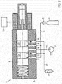
- the proportional valve used in the device 1 is designed here as a 3/2-way valve and includes a housing 7 in which a valve piston 8 against the force of a spring 9 is axially displaceable.
- the valve piston 8 is controlled by an electromagnet 10 by a controller 11.
- the valve piston 8 is divided successively into different regions in the axial direction, with two deflecting regions 12a and 12b and two closing regions 13a and 13b alternating in the illustrated embodiment.
- the housing 7 is penetrated by inlet and / or outlet openings, wherein an inlet opening 14 is connected via a compressed air line 15 to the compressed air source 2.
- an inlet opening 14 is connected via a compressed air line 15 to the compressed air source 2.
- two openings 16, 17 are provided, which are connected via the Blas Kunststofftechnisch 5 with the blow mold.
- two openings 18 and 19 are provided, which are connected via a vent line 20 with the environment, preferably via a silencer 21st
- a course of a mass flow of the blowing air is predetermined as a function of the predetermined sequence of the blowing process. This predetermined course is then realized during the blowing by changes in the flow cross-section of the openings 14, 16, 17, 18, 19.
- valve piston 8 of the proportional valve 6 is displaced via the controller 11 in the illustrated embodiment such that the second deflection space 12b connects the compressed air inlet opening 14 with the opening 16 to the blow mold.
- the leading to the vent line 20 openings 18 and 19 are closed by the adjusting portions 13 a, 13 b, and the opening 17 is open in the first deflection space 12 a and serves to equalize the pressure.
- valve piston 8 is displaced according to a predetermined course M of the mass flow stored in the controller 11, whereby the flow area of the orifice 16 is increased and decreased in the predetermined manner.
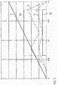
- Fig. 5 shows a diagram with different curves, where on the x-axis the time in seconds and on the y-axis the valve position, the mass flow and the stretching path are plotted. This figure indicates a procedure known from the prior art.
- Fig. 5 is an example of a preferred, time course M of the mass flow M applied (dash-dotted curve).
- the curve of the opening positions of the flow cross-section along the curve D corresponds to the predetermined time course of the mass flow M.
- a Vorblasvorgang can be seen, in which the flow cross-section increases up to a first maximum value, passes through the first maximum value of the mass flow in the preform.
- first a first inflation of the preform is achieved until there is a pressure equalization between the blowing air in the interior of the preform / the bladder and the material response of the plastic to be stretched. Since the pressure decreases with increasing flow of the material, an actuating response would take place here in a conventional pressure control and the pressure would be readjusted.
- the mass flow according to the curve M is brought to a second maximum value, which is higher than the maximum value during pre-blowing. Accordingly, the flow area is opened stronger than is required for the pre-blowing.
- the mass flow is reduced and, accordingly, the flow cross section is reduced.
- the distribution of the material in the region between the bottom and the inlet opening of the container 4 can be influenced.
- the distribution of the material between the center of the container and the bottom is made uniform.
- Fig. 5 Furthermore, the percentage stretching path from 0 to 100%, ie from the preform to the finished container, is applied as a straight line R.
- Fig. 5 shows that by simply turning on and off the compressed air supply, with a proper adjustment of the pressure of the compressed air, the container is stretched to 100%, on the course of the mass flow between 0 and 100% stretching, however, no influence can be taken.
- a device 22 for checking the mass flow of the compressed air can be arranged in the blown air line 5 to the blow mold or at another suitable location.
- This device 22 for example, one of the conventional flow meter, is connected to the controller 11 and may optionally regulate intervene when the actual mass flow deviates from the predetermined mass flow.
- quality inspection facilities such as measuring devices of the wall thickness, also be connected to the controller 11 and, for example, either change the predetermined curve M of the mass flow for all subsequent blowing operations or make other changes.
- the blowing pressure can be monitored as usual and the detected pressure values z. B. are processed for documentation in a blow-curve.
- the course M of the mass flow of the blown air, after the flow cross section is changed but except as a time course, as in Fig. 5 represented as a course depending on certain process parameters or certain process states.
- the course of the mass flow of the blown air can also be predetermined as a function of a specific point of a blowing wheel of a conventional blow molding machine, so that each position of the blower wheel is assigned a specific flow cross section of the blown air supply.
- the container 4 can be vented after the finished blowing in a simple manner.
- the ventilation position is in Fig. 2 shown.
- the valve piston 8 is moved to a position in which the inlet opening 14 of the compressed air line 15 is closed by the compressed air source 2, both openings 16, 17 are connected to the blown air line 5 to the blow mold and the other two openings 18, 19 with the vent line 20.
- one of the openings 16, 17 to the blow mold is connected together with one opening 18 and 19 to the vent line 20 with the same deflection space 12a and 12b.
- the valve 6 is fully opened, so is the double flow area, compared with the blowing process according to Fig. 1 , for venting the finished container 4 available, so that the vent can take place very quickly, which leads to a shortening of the blowing cycle.
- blowing air starting from the ready-expanded expanded container, be led back into at least one pressure reservoir, in particular into that reservoir which supplies the lower pressure stage, ie. provides the pressure p1.
- This feedback is preferably carried out again via the flow cross-section change element, in particular the proportional valve.
- the flow cross-section change element in particular the proportional valve.
- its maximum flow or the flow cross-section of the flow cross-section changing element is maximum.
- the Fig. 3 and 4 show a further embodiment of an apparatus 100 for carrying out a blow molding process, wherein the same or comparable components are denoted by the same reference numerals and are not explained again.
- the device 100 also uses a proportional valve 6 as means for varying the mass flow the blown air, wherein the proportional valve 6 of the device 100 corresponds in construction and control of the proportional valve of the device 1.
- Fig. 3 shows the blowing process.
- the device 100 includes a compressed air source 2, which here comprises two compressors or two compressor stages of a compressor 2a and 2b.
- the vent valve 23 includes two outlet openings 24 and 25.
- the outlet opening 24 leads via the muffler 21 in the ambient air.
- the opening 25 leads via a recycling line 26 into the compressed air source 2, preferably between the two compressor stages 2a, 2b.
- the vent valve 23 also has two inlet openings 27 and 28, which are both connected to the vent line 20.
- the vent valve 23 includes an axially displaceable valve piston 29 which connects the inlet port 27 selectively with one of the two outlet openings 24, 25.
- the valve piston 29 is acted upon by a front side through the vent line 20 and is supported on the other end face on a spring 30 from.
- the spring 30 determines the switching pressure, beyond which the valve piston 29 moves.
- the switching pressure is preferably 20 bar.
- the valve piston 29 is moved to a position in which the vent line 20 is connected to the recycling line 26 , so that the blowing air escaping from the container 4 is returned to the compressed-air source 2.
- Fig. 6 shows a system for producing containers 4, wherein the preforms are stored in a memory 31 and separated in a separating device 32, aligned and fed to a heating oven 33 for heating.
- each preform is impressed with a temperature profile which allows a defined deformation in each direction.
- they are supplied via the inlet star 35 to the blowing wheel 36, are attached to the equidistant blowing stations, not shown here.
- the blow stations each have at least one device 6 for the controlled supply of blown air and in usually also a preform with respect to its longitudinal axis stretching stretch rod.
- the reference numeral 34 indicates the conversion device in its entirety
- the blowing wheel 36 thus represents the above-mentioned transport device for transporting the plastic preforms or the plastic containers.
- the reference numeral 38 schematically indicates a forming station arranged on the blowing wheel.
- the conversion stations 38 are guided along a substantially circular path.
- each blowing station is designed to carry out the method according to the invention.
- the blowing stations may also have a plurality of devices 6 which take over the air distribution / air control during the manufacture of the containers.
- a second means 6 per blowing station for controlling the air recovery from the bottle may be present.
- the finished container 4 are passed from the blowing wheel 36 by means of an outlet star 37 to the following machines.
- any other suitable means for changing the flow area for the blown air can be used.
- Fig. 7 shows a representation of a pressure curve for a method according to the invention. The time is plotted on the x-axis and the pressure on the y-axis. The dashed horizontal lines indicate the two pressure levels p1 and p2. It is at the in Fig. 7 shown situation, the pressure p1 about half as large as the pressure p2
- a pre-blowing of the plastic preform takes place.
- the cross section of the p1 valve which may in particular be a proportional valve of the type described above
- a material distribution of the plastic preform to be expanded can be optimized.
- this pressure p1 is approximately half the pressure p2.
- step II an extended pre-blowing takes place instead of the intermediate blowing usually carried out in the prior art.
- the flow cross section of the proportional valve is fully opened in order to optimize the process angle.
- process step III the container is completely blown under the higher pressure p2.
- the valve which supplies the blown air under the pressure p1 closed.
- process step IV the blowing air is recycled.
- blowing air is fed back into the reservoir at the pressure p1.
- This supply is advantageously carried out via the flow cross-section modification device. in particular the proportional valve.
- the maximum flow cross-section or the maximum volume flow is permitted so as to minimize the recycling period.
- method step V the container is unloaded.
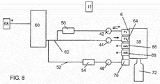
- Fig. 8 shows a schematic representation of a device according to the invention.
- a provision unit 58 is provided for providing compressed air or process air.
- This provision unit 58 which may be for example a compressor, is advantageously arranged stationary.
- the reference numeral 60 refers to a distribution device which divides the process air to the individual conversion stations.
- This distributor is preferably designed as a so-called. Rotary distributor.
- compressed air is supplied on the one hand a control air line 52 and on the other hand, a process air line 62.
- the compressed air is again divided here into a first compressed air reservoir 42 and a second compressed air reservoir 44.
- These compressed air reservoirs are preferably annular channels which are arranged on the rotating part of the device.
- the reference numeral 6 refers here again to a first valve device, which is designed here as a proportional valve and which controls the supply of compressed air with the pressure level p1 to the plastic container 72.
- Reference numeral 64 denotes a second valve device which controls the compressed air supply of compressed air at the second pressure p2 to the container.
- Reference numeral 56 denotes a pressure regulating means which controls the pressure p1.
- the air in the control line is fed via a pressure control device 54 to another compressed air reservoir 46, which is also designed as an annular channel.
- Reference numerals 66 and 68 refer to exhaust valves.
- the reference numeral 11 denotes a (only roughly schematically shown) control device which controls the supply of compressed air into the plastic containers.
- one or more measuring devices can be provided for measuring a volume or mass flow.
Description
Die vorliegende Erfindung bezieht sich auf ein Verfahren und eine Vorrichtung zum Umformen von Kunststoffvorformlingen zu Kunststoffbehältnissen. Derartige Verfahren und Vorrichtungen sind aus dem Stand der Technik seit langem bekannt. Dabei werden üblicherweise erwärmte Kunststoffvorformlinge durch Beaufschlagung mit Druckluft zu Kunststoffbehältnissen umgeformt. Im Stand der Technik werden dabei üblicherweise mehrere Druckstufen eingesetzt, um die Kunststoffvorformlinge zu expandieren. So ist bekannt, dass zunächst mit einem geringeren Druck ein Vorblasen vorgenommen wird und anschließend mit einem erhöhten Druck ein Fertigblasen der Kunststoffvorformlinge. Daneben wird im Stand der Technik üblicherweise ein Zwischenblasen eingesetzt, welches zeitlich zwischen dem Vorblasen und dem Fertigblasen liegt. Durch diese Vielzahl von unterschiedlichen Druckstufen entsteht eine vergleichsweise hohe Komplexität an Reservoirs, die üblicherweise als Ringkanäle ausgeführt sind. Auch ist der eigentliche Verfahrensablauf zum Umformen der Kunststoffvorformlinge relativ kompliziert. Andererseits war man bisher davon ausgegangen, dass insbesondere auch das Vorsehen des Zwischenblasdruckniveaus den Blasformprozess stark vereinfacht bzw. verbessert. Derartige Verfahren und Vorrichtungen sind in den Druckschriften
Der vorliegenden Erfindung liegt daher die Aufgabe zugrunde, eine Möglichkeit zu schaffen, welche einerseits die hohe Komplexität der unterschiedlichen Druckreservoirs reduziert und andererseits dennoch zu zufriedenstellenden Blasformergebnissen führt. Diese Aufgabe wird erfindungsgemäß durch die Gegenstände der unabhängigen Ansprüche erreicht. Vorteilhafte Ausführungsformen und Weiterbildungen sind Gegenstand der Unteransprüche.It is therefore an object of the present invention to provide a possibility which, on the one hand, reduces the high complexity of the different pressure reservoirs and, on the other hand, nevertheless leads to satisfactory blow-molding results. This object is achieved by the subject of the independent claims. Advantageous embodiments and further developments are the subject of the dependent claims.
Bei einem erfindungsgemäßen Verfahren zum Umformen von Kunststoffvorformlingen zu Kunststoffbehältnissen und insbesondere Kunststoffflaschen werden die Kunststoffvorformlinge mittels einer Transporteinrichtung in einer Vielzahl von an dieser Transporteinrichtung angeordneten Umformungsstationen entlang eines vorgegebenen Transportpfades transportiert und wenigstens zeitweise während dieses Transports zu ihrer Expansion mit einem fließfähigen Medium beaufschlagt. Weiterhin werden die Kunststoffvorformlinge in einem ersten Verfahrensschritt mit dem unter einem ersten Druck stehenden, fließfähigen Medium beaufschlagt und in einem auf diesem ersten Verfahrensschritt zeitlich nachfolgenden weiteren Verfahrensschritt mit dem unter einem zweiten Druck p2 stehenden fließfähigen Medium beaufschlagt, wobei der zweite Druck p2 höher ist als der erste Druck p1.In a method according to the invention for forming plastic preforms into plastic containers and in particular plastic bottles, the plastic preforms are transported along a predetermined transport path by means of a transport device in a multiplicity of forming stations arranged on this transport device and subjected to a flowable medium at least temporarily during this transport for their expansion. Furthermore, in a first method step, the plastic preforms are subjected to the flowable medium under a first pressure and subjected to the flowable medium under a
Erfindungsgemäß wird wenigstens zeitweise während der Beaufschlagung der Kunststoffvorformlinge mit dem ersten Druck ein Volumenstrom des in das Behältnis gelangenden fließfähigen Mediums verändert und insbesondere erhöht.According to the invention, at least temporarily, during the application of the first pressure to the plastic preforms, a volume flow of the flowable medium entering the container is changed and, in particular, increased.
Es wird daher bevorzugt vorgeschlagen, dass kein Zwischenblasen mehr erfolgt, sondern lediglich ein (insbesondere zeitlich verlängertes) Vorblasen bzw. ein Beaufschlagen mit dem geringeren Druck P1. Allerdings wird bevorzugt im Laufe des Expansionsprozesses der Strömungsquerschnitt verändert und insbesondere erhöht. So ist es beispielsweise möglich, dass während oder nach dem Vorblasen ein automatisches Programm abläuft, in dem ein Querschnitt eines Ventils geöffnet, insbesondere voll geöffnet wird und damit der anstehende Druck im Wesentlichen vollständig in den Kunststoffvorformling bzw. das Behältnis eingebracht wird. Neben dem Begriff Behältnis wird im Folgenden auch synonym der Begriff Behälter verwendet.It is therefore preferably proposed that no intervening bubbles more, but only one (in particular temporally prolonged) Vorblasen or a pressurization with the lower pressure P1. However, in the course of the expansion process, the flow cross section is preferably changed and in particular increased. Thus, for example, it is possible for an automatic program to take place during or after the pre-blowing in which a cross-section of a valve is opened, in particular fully opened, and thus the pending pressure is substantially completely introduced into the plastic preform or the container. In addition to the term container, the term container is also used interchangeably below.
Bevorzugt wird der Kunststoffvorformling lediglich mit zwei unterschiedlichen Druckniveaus beaufschlagt. Damit wird besonders bevorzugt auf das Vorsehen eines weiteren Druckniveaus für das Zwischenblasen verzichtet. Bevorzugt folgt damit auf die Beaufschlagung mit dem ersten Druck unmittelbar die Beaufschlagung mit dem zweiten Druck ohne weitere dazwischenliegende Druckniveaus.Preferably, the plastic preform is acted upon only with two different pressure levels. This is particularly preferred to dispense with the provision of a further pressure level for the intermediate bubbles. Preference is thus given to the application of the first pressure immediately followed by the application of the second pressure without further intermediate pressure levels.
Bevorzugt werden die Kunststoffvorformlinge entlang eines im Wesentlichen kreisförmigen Transportpfades transportiert. Dabei ist es möglich, dass die Transporteinrichtung ein drehendes Rad wie beispielsweise ein Blasrad aufweist, an dem die Umformungsstationen angeordnet sind und mit dem die Umformungsstationen bewegt werden. Bevorzugt handelt es sich bei dem ersten Druck um einen konstanten Druck, d.h. der Druck wird während der ersten Phase des Umformungsprozesses, also dem Vorblasen, konstant gehalten. Vorteilhaft handelt es sich auch bei dem zweiten Druck um einen konstanten Druck, d.h. auch dieser Druck wird bevorzugt während der zweiten Phase des Prozesses, also dem Fertigblasen, konstant gehalten.Preferably, the plastic preforms are transported along a substantially circular transport path. It is possible that the transport device has a rotating wheel such as a blowing wheel on which arranged the forming stations are and with which the transformation stations are moved. The first pressure is preferably a constant pressure, ie the pressure is kept constant during the first phase of the deformation process, that is, the pre-blowing. Advantageously, the second pressure is also a constant pressure, ie this pressure is also preferably kept constant during the second phase of the process, that is to say the ready-blowing.
Bei einem weiteren bevorzugten Verfahren werden die Kunststoffvorformlinge während des Umformungsvorgangs in ihrer Längsrichtung gestreckt. Vorteilhaft wird zu diesem Zweck ein stangenartiger Körper wie insbesondere, aber nicht ausschließlich eine Reckstange in die Kunststoffvorformlinge eingeführt, um diese zu strecken.In a further preferred method, the plastic preforms are stretched in their longitudinal direction during the forming process. Advantageously, for this purpose, a rod-like body as in particular, but not exclusively a stretching rod introduced into the plastic preforms in order to stretch them.
Bei einer weiteren vorteilhaften Ausführungsform werden der erste und/oder zweite Druck durch Druckreservoirs zur Verfügung gestellt. Vorteilhaft kann es sich bei diesen Druckreservoirs um Ringkanäle handeln, welche in der Lage sind, mehrere und bevorzugt alle Umformungsstationen der Vorrichtung mit dem unter Druck stehenden Medium zu versorgen. Vorteilhaft wird die Druckzufuhr in die Behältnisse durch die Verwendung von Ventilen gesteuert. So können beispielsweise Ventile sowohl die Steuerung des Vorblasdruckes als auch die Steuerung des Fertigblasdruckes bewirken.In a further advantageous embodiment, the first and / or second pressure are provided by pressure reservoirs. Advantageously, these pressure reservoirs can be ring channels which are able to supply a plurality and preferably all transformation stations of the device with the medium under pressure. The pressure supply into the containers is advantageously controlled by the use of valves. For example, valves can cause both the control of the Vorblasdruckes as well as the control of the Fertigblasdruckes.
Bevorzugt liegt der zweite Druck zwischen 10 bar und 50 bar, bevorzugt zwischen 15 bar und 40 bar und besonders bevorzugt zwischen 20 bar und 30 bar. Bevorzugt liegt der erste Druck zwischen 5 bar und 40 bar, bevorzugt zwischen zehn bar und 30 bar und besonders bevorzugt zwischen 15 bar und 25 bar. Bei einem weiteren bevorzugten Verfahren stehen der erste und der zweite Druck in einem Verhältnis zueinander, welches zwischen 1 : 3 und 2 : 3, bevorzugt zwischen 2 : 5 und 3 : 5 liegt. Besonders bevorzugt beträgt der erste Druck etwa die Hälfte des zweiten Drucks. Vorteilhaft handelt es sich bei dem fließfähigen Medium, mit dem die Kunststoff-Vorformlinge beaufschlagt werden, um ein gasförmiges Medium und insbesondere um Blasluft.The second pressure is preferably between 10 bar and 50 bar, preferably between 15 bar and 40 bar and particularly preferably between 20 bar and 30 bar. The first pressure is preferably between 5 bar and 40 bar, preferably between 10 bar and 30 bar and particularly preferably between 15 bar and 25 bar. In another preferred method, the first and second pressures are in a ratio of one another which is between 1: 3 and 2: 3, preferably between 2: 5 and 3: 5. Particularly preferably, the first pressure is about half of the second pressure. Advantageously, the flowable medium, which is applied to the plastic preforms, is a gaseous medium and, in particular, blowing air.
Von besonderem Vorteil ist die Verwendung eines an sich aus der Hydraulik bekannten Proportionalventils, da dieses schnell schaltet und auch für einen hohen Durchfluss ausgelegt werden kann.Of particular advantage is the use of a known per se from the hydraulic proportional valve, as this switches quickly and can be designed for a high flow.
Bei einem vorteilhaften Verfahren können verschiedene Überwachungsfunktionen vorgesehen sein. So kann der Verlauf des Massenstroms bei Qualitätsabweichungen am Behälter gegebenenfalls korrigiert werden. So ist es möglich, den hergestellten Behälter "in-line", also nach der Herstellung aber noch in der Maschine / Anlage zu überprüfen, so z.B. die Wanddicke, die Bodenmasse oder die Bodengeometrie des Behälters, um dann direkt eine Anpassung des Massenstromes und/oder Volumenstroms vorzunehmen.In an advantageous method, various monitoring functions can be provided. If necessary, the course of the mass flow can be corrected if the quality deviates from the container. Thus, it is possible to check the container produced "in-line", ie after production but still in the machine / plant, such. the wall thickness, the soil mass or the bottom geometry of the container to then make an adjustment of the mass flow and / or volume flow directly.
Es ist weiterhin möglich, den Massenstrom und/oder Volumenstrom zu messen und zur Regelung desselben einzusetzen.It is also possible to measure the mass flow and / or flow rate and use it to control the same.
Bei Verwendung eines Proportionalventils kann dieses gleichzeitig zum Entlüften des Behälters nach dem Ende des Blasvorgangs eingesetzt werden, so dass hier zusätzliche Vorkehrungen nicht mehr notwendig sind.When using a proportional valve this can be used at the same time for venting the container after the end of the blowing process, so that additional precautions are no longer necessary.
In Verbindung mit einem weiteren Ventil kann das Proportionalventil bevorzugt auf einfache Weise auch zum Recyceln der Blasluft verwendet werden.In conjunction with another valve, the proportional valve can be used in a simple manner also for recycling the blown air.
Das Proportionalventil kann auf verschiedene Arten ausgestaltet sein, wie z.B. mit einem Ventilschieber oder einem Ventilkegel. Weiterhin kann eine bauliche Variation so aussehen, dass der Schieber bzw. der Kegel die Positionen durch feste Anschläge einnimmt, er kann aber auch lagegeregelt sein. Eine Lageregelung ist zwar komplizierter, aber genauer.The proportional valve may be configured in various ways, e.g. with a valve spool or a valve cone. Furthermore, a structural variation can be such that the slider or the cone occupies the positions by fixed stops, but it can also be position-controlled. A position control is more complicated, but more accurate.
In der gesamten Beschreibung ist immer die Rede von der Steuerung bzw. Regelung des Volumenstroms bzw. Massenstromes des Fluids. Da der Massenstrom über die Dichte des Fluids direkt mit dem Volumenstrom zusammenhängt, ist das beschriebene Verfahren ggfs. anstatt als volumenstromgesteuert auch als massenstromgesteuert durchzuführen.Throughout the description, there is always talk of the control or regulation of the volume flow or mass flow of the fluid. Since the mass flow is directly related to the volume flow via the density of the fluid, the process described is optionally, instead of volume flow controlled, also carried out as a mass flow control.
Bei einer weiteren vorteilhaften Ausführungsform werden die Kunststoffvorformlinge während eines ersten Zeitraums mit dem ersten Druck beaufschlagt und während eines zweiten Zeitraums mit dem zweiten Druck, wobei diese Zeiträume in einem Verhältnis zueinander stehen, welches zwischen 1:2 und 1:20 liegt. Bevorzugt wird daher der Zeitraum, über den hinweg die Kunststoffvorformlinge mit dem Druck p1 beaufschlagt werden gegenüber Verfahren aus dem Stand der Technik erhöht.In a further advantageous embodiment, the plastic preforms are subjected to the first pressure during a first time period and to the second pressure during a second time period, wherein these time periods are in a relationship which lies between 1: 2 and 1:20. Preferably, therefore, the period over which the plastic preforms are subjected to the pressure p1 is increased compared to prior art methods.
Bei einem weiteren vorteilhaften Verfahren wird der erste Druck durch ein erstes Druckreservoir zur Verfügung gestellt und wenigstens zeitweise fließfähiges Medium ausgehend von wenigstens einer Umformungsstation diesem ersten Druckreservoir zur Verfügung gestellt. Es wird also hier vorgeschlagen, dass ein Teil der zum Blasen verwendeten Druckluft wieder recycelt wird. Da wie oben erwähnt der Fertigblasdruck erheblich höher liegt als der Vorblasdruck, ist es nach erfolgter Umformung der Kunststoffvorformlinge möglich, einen Teil dieses Druckes wieder aus dem Behältnis zurück in das Druckreservoir für den Vorblasdruck zu führen.In a further advantageous method, the first pressure is provided by a first pressure reservoir and, at least temporarily, flowable medium is made available to this first pressure reservoir from at least one transformation station. It is therefore proposed here that part of the compressed air used for blowing is recycled. As mentioned above, the Fertigblasdruck is considerably higher than the Vorblasdruck, it is possible after reshaping of the plastic preforms to lead a portion of this pressure back from the container back into the pressure reservoir for the Vorblasdruck.
Bei einem weiteren vorteilhaften Verfahren erfolgt eine Steuerung der Zuführung des fließfähigen Mediums in die Kunststoffvorformlinge bzw. zu den Kunststoffvorformlingen in Abhängigkeit von einer Umfangsposition der jeweiligen Umformungsstationen. Daher wird hier insbesondere eine drehwinkelabhängige Steuerung des Blasprozesses vorgeschlagen.In a further advantageous method, the supply of the flowable medium into the plastic preforms or to the plastic preforms is controlled as a function of a peripheral position of the respective forming stations. Therefore, in particular a rotation angle-dependent control of the blowing process is proposed here.
Wie oben erwähnt wird damit bevorzugt eine Steuerung des Strömungsquerschnitts mittels eines elektrischen Ventils vorgeschlagen, d.h. insbesondere eines Ventils, welches eine elektrische Verstellung des Strömungsquerschnitts erlaubt. Dabei ist der Volumenstrom über einen Querschnitt bzw. Öffnungsquerschnitt des Ventils einstellbar. So kann nach dem Vorblasen ein automatisches Programm ablaufen, in dem der Strömungsquerschnitt voll geöffnet wird. Dabei ist es möglich, dass eine Öffnung dieses Strömungsquerschnitts kontinuierlich erfolgen kann, es wären jedoch auch Öffnungen mit einem gestuften Verlauf denkbar. Nach der Öffnung des Ventils wird bevorzugt eine Umschaltung auf das zweite Druckniveau p2 durchgeführt, wobei es sich hierbei bevorzugt um eine Schwellwertumschaltung handelt. Diese kann beispielsweise bei einem Druckniveau von einem bar unter dem p1-Druck erfolgen.As mentioned above, it is thus preferred to control the flow cross-section by means of an electric valve, i. in particular a valve, which allows an electrical adjustment of the flow cross-section. In this case, the volume flow over a cross-section or opening cross-section of the valve is adjustable. Thus, after the pre-blowing run an automatic program in which the flow cross-section is fully opened. It is possible that an opening of this flow cross-section can take place continuously, but it would also be possible openings with a stepped course. After the opening of the valve, a switchover to the second
Der Luftverbrauch wird dann theoretisch etwas höher, weil nur noch in einen Kanal recycelt wird. Jedoch wird dieser Unterschied sehr gering, je niedriger der höhere Druck p2 wird, weil auch in den aus dem Stand der Technik bekannten Systemen der Vorblasdruck p1 und der Zwischenblasdruck Pi annähernd das gleiche Druckniveau aufweisen. Die Anmelderin konnte ermitteln, dass im Ergebnis dennoch eine Verbesserung zu erwarten ist.The air consumption is then theoretically a little higher, because only one channel is recycled. However, this difference becomes very small, the lower the higher pressure p2, because even in the systems known from the prior art, the pre-blowing pressure p1 and the intermediate blowing pressure Pi have approximately the same pressure level. The applicant was able to determine that the result should still be expected to improve.
Durch jüngere Entwicklungen im Bereich der Entlüftung wird jedoch der p2-Druck mittelfristig im Bereich von 20 bis 30 Bar, bevorzugt bei etwa 25 Bar liegen, was dazu führt, dass der Pi-Druck des Zwischenblasens bei etwa 12 bar liegt, d.h. im Bereich des p1-Druckniveaus. Durch die vorgeschlagene Vorgehensweise wird das Recyceln von Druckluft einfacher und schneller, da der Querschnitt des Ventils vollständig geöffnet ist. Daneben können auch feste Grenzen für die Steuerung und die Druckniveaus angegeben werden. Bisher ist es unbekannt, wie viel Luft aus dem Druckreservoir für den Druck p1 stammt und wie viel Luft aus dem Druckreservoir für den Druck Pi stammt. Entsprechend verschieben sich auch die jeweiligen Prozesswinkel.However, due to recent developments in the field of venting, the p2 pressure will be in the range of 20 to 30 bar, preferably about 25 bar, in the medium term, which results in the Pi pressure the intermediate blowing is about 12 bar, ie in the range of the p1 pressure level. The proposed approach makes recycle of compressed air easier and faster because the cross-section of the valve is fully open. In addition, fixed limits for the control and the pressure levels can be specified. So far, it is unknown how much air comes from the pressure reservoir for the pressure p1 and how much air comes from the pressure reservoir for the pressure Pi. Accordingly, the respective process angles are also shifting.
Weiterhin entfällt einmal die Schaltzeitverzögerung. Ein kompletter Ringkanal einschließlich Ventil sowie auch eine Vielzahl von Parametern in einem Bediengerät wie etwa einem Touchscreen können entfallen. Dadurch dass auf das Zwischendruckniveau vollständig verzichtet wird, wird auch das Luftrecycling deutlich vereinfacht. Eine fehlerhafte Einstellung des Pi-Systems und des Recyclings können so vermieden werden.Furthermore, once the switching time delay is eliminated. A complete annular channel including valve as well as a variety of parameters in an operating device such as a touch screen can be omitted. By completely eliminating the intermediate pressure level, air recycling is also greatly simplified. Incorrect setting of the Pi system and recycling can thus be avoided.
Die vorliegende Erfindung ist weiterhin auf eine Vorrichtung zum Umformen von Kunststoffvorformlingen zu Kunststoffflaschen bzw. Kunststoffbehältnissen gerichtet. Diese Vorrichtung weist eine bewegliche Transporteinrichtung mit einer Vielzahl von Umformungsstationen auf, welche an dieser Transporteinrichtung angeordnet sind und von dieser transportiert werden. Dabei weist jede dieser Umformungsstationen jeweils wenigstens eine Beaufschlagungseinrichtung zum Beaufschlagen der Kunststoffvorformlinge mit einem fließfähigen Medium auf. Weiterhin weist die Vorrichtung ein erstes Druckluftreservoir auf, welches das fließfähige Medium mit einem ersten Druck zur Verfügung stellt sowie ein zweites Druckluftreservoir, welches die Druckluft mit einem zweiten Druck zur Verfügung stellt, wobei der zweite Druck höher ist als der erste Druck und wobei die Vorrichtung weiterhin eine Steuerungseinrichtung aufweist, welche die Zuführung des fließfähigen Mediums in die Kunststoffvorformlinge steuert.The present invention is further directed to an apparatus for forming plastic preforms into plastic bottles or plastic containers. This device has a movable transport device with a plurality of conversion stations, which are arranged on this transport device and transported by this. In this case, each of these transformation stations each have at least one loading device for applying a flowable medium to the plastic preforms. Furthermore, the apparatus comprises a first compressed air reservoir, which provides the flowable medium with a first pressure and a second compressed air reservoir, which provides the compressed air at a second pressure, wherein the second pressure is higher than the first pressure and wherein the device furthermore has a control device which controls the supply of the flowable medium in the plastic preforms.
Erfindungsgemäß weist die Vorrichtung eine Strömungsquerschnittsveränderungseinrichtung auf, welche eine Veränderung eines Strömungsquerschnitts des in die Behältnisse gelangenden fließfähigen Mediums wenigstens zeitweise erlaubt. Weiterhin ist die Steuerungseinrichtung derart gestaltet, dass wenigstens zeitweise während der Beaufschlagung der Kunststoffvorformlinge mit dem ersten Druck ein Volumenstrom des in das Behältnis gelangenden fließfähigen Mediums verändert und insbesondere erhöht wird. Es wird daher auch vorrichtungsseitig vorgeschlagen, dass mittels einer Strömungsquerschnittsveränderungseinrichtung ein Strömungsquerschnitt verändert wird.According to the invention, the device has a flow cross-section modification device which permits a change in a flow cross-section of the flowable medium entering the containers at least temporarily. Furthermore, the control device is designed such that at least temporarily changed during the application of the plastic preforms with the first pressure, a volume flow of the entering into the container flowable medium and in particular increased. It will therefore also device side proposed that a flow cross-section is changed by means of a flow cross-section modification device.
Vorteilhaft handelt es sich bei der Strömungsquerschnittsveränderungseinrichtung um ein Proportionalventil, um die Zufuhr des fließfähigen Mediums unter dem ersten Druck zu steuern.Advantageously, the flow cross-section variation device is a proportional valve in order to control the supply of the flowable medium below the first pressure.
Bei einer weiteren vorteilhaften Ausführungsform weist die Vorrichtung wenigstens eine Verbindungsleitung auf, mittels derer das fließfähige Medium von wenigstens einer Umformungsstation in das erste Reservoir geführt werden kann. Damit wird hier ebenfalls wieder eine Leitungsverbindung vorgeschlagen, welche ein Recyceln von Blasluft ermöglicht. Vorteilhaft ist in einer Verbindungleitung zwischen der besagten Umformungsstation und wenigstens einem Druckluftreservoir eine Querschnittsveränderungseinrichtung angeordnet, welche eine Veränderung des Volumenstroms oder Massenstroms des von der Umformungsstation zu diesem Reservoir gelangenden fließfähigen Mediums erlaubt.In a further advantageous embodiment, the device has at least one connecting line, by means of which the flowable medium can be guided by at least one forming station in the first reservoir. Thus, here again a line connection is proposed, which allows recycling of blown air. Advantageously, a cross-sectional modification device is arranged in a connection line between the said transformation station and at least one compressed air reservoir, which permits a change in the volume flow or mass flow of the flowable medium reaching from the conversion station to this reservoir.
Bei einer weiteren vorteilhaften Ausführungsform weist die Vorrichtung wenigstens eine Messeinrichtung zur Bestimmung eines Volumenstroms des fließfähigen Mediums auf. So ist es möglich, dass auch in Abhängigkeit von dieser Messeinrichtung ausgegebenen Daten der Strömungsquerschnitt des in die Kunststoffvorformlinge gelangenden fließfähigen Mediums gesteuert wird.In a further advantageous embodiment, the device has at least one measuring device for determining a volumetric flow of the flowable medium. Thus, it is also possible that the flow cross-section of the flowable medium entering the plastic preforms is also controlled as a function of data output by this measuring device.
Bevorzugt werden die beiden Druckluftreservoirs von einer Drucklufterzeugungseinrichtung wie etwa einem Kompressor gespeist. Bei einer weiteren vorteilhaften Ausführungsform sind die Druckluftreservoirs als Ringkanäle ausgebildet, welche sämtliche Umformungsstationen mit Druckluft versorgen.
- Fig. 1
- ein erstes Ausführungsbeispiel einer zur Durchführung des erfindungsgemäßen Verfahrens geeigneten Vorrichtung in schematischer Teildarstellung beim Belüften eines Behälters,
- Fig. 2
- die Vorrichtung nach
Fig. 1 beim Entlüften eines Behälters, - Fig. 3
- ein zweites Ausführungsbeispiel einer zum Durchführen des erfindungsgemäßen Verfahrens geeigneten Vorrichtung in schematischer Teildarstellung beim Belüften eines Behälters,
- Fig. 4
- die Vorrichtung nach
Fig. 3 in einer die Blasluft recycelnden Stellung, - Fig. 5
- ein Diagramm der Ventilsteuerung und des vorbestimmten Verlaufs des Massenstroms über der Zeit,
- Fig. 6
- eine Draufsicht auf eine Anlage zum Herstellen von Behältern, insbesondere Kunststoffflaschen,
- Fig. 7
- eine Darstellung eines Druckverlaufs während eines Expansionsvorgangs, und
- Fig. 8
- eine weitere Darstellung einer erfindungsgemäßen Vorrichtung.
- Fig. 1
- a first embodiment of an apparatus suitable for carrying out the method according to the invention in a schematic partial representation when venting a container,
- Fig. 2
- the device after
Fig. 1 when venting a container, - Fig. 3
- A second embodiment of an apparatus suitable for carrying out the method according to the invention in a schematic partial representation when venting a container,
- Fig. 4
- the device after
Fig. 3 in a recycling air blowing position, - Fig. 5
- a diagram of the valve timing and the predetermined course of the mass flow over time,
- Fig. 6
- a top view of a plant for producing containers, in particular plastic bottles,
- Fig. 7
- a representation of a pressure curve during an expansion process, and
- Fig. 8
- a further illustration of a device according to the invention.
Aus den
Die Vorrichtung 1 enthält eine Druckluftquelle 2, die bevorzugt als ein- oder mehrstufiger Kompressor ausgebildet oder mit diesem verbunden ist. Die Druckluftquelle 2 sollte in der Lage sein, Druckluft von 0 bis zu 40, bevorzugt bis zu 50 bar bereitzustellen.The
Daneben weist die Vorrichtung zwei Druckluftreservoirs auf (nicht in
Die Vorrichtung 1 enthält weiterhin eine der üblichen Blasformen, die hier nicht dargestellt ist. In die Blasformen wird ein Vorformling oder ein Preform aus Kunststoff, insbesondere PET, herkömmlicher Art eingesetzt und als Behälter 4 wieder entnommen. Die Blasform steht über eine Blasluftleitung 5 mit der Druckluftquelle 2 in Verbindung. In die Blasluftleitung 5 ist eine Einrichtung 6 zum Verändern eines Massenstroms der in die Blasform eingeleiteten Druckluft eingeschaltet. Als Einrichtung 6 kann jedes Element verwendet werden, das in der Lage ist, mit der für eine korrekte Durchführung des Blasvorgangs notwendigen Geschwindigkeit zu schalten, und das einen Durchflussquerschnitt einer Blasluftleitung über einen ausreichend großen Bereich verändern kann, um die unterschiedlichen Massenströme der Blasluft, die zum Erreichen einer bestimmten Form des Behälters 4 notwendig sind, bereitstellen zu können. Die Einrichtung 6 ist bevorzugt als Proportionalventil ausgebildet, wobei ein übliches Proportionalventil aus der Hydraulik verwendet und an den Einsatzzweck zum Verändern eines Massenstroms von Druckluft angepasst wird. Insbesondere kann das Proportionalventil 6 so verändert werden, dass der Einfluss von Positionierungsungenauigkeiten auf den durchfließenden Massenstrom minimiert wird, der Durchfluss somit wesentlich weniger sensibel auf eine Positionierungenauigkeit reagiert.The
Das in der Vorrichtung 1 verwendete Proportionalventil ist hier als 3/2-Wegeventil ausgebildet und enthält ein Gehäuse 7, in dem ein Ventilkolben 8 gegen die Kraft einer Feder 9 axial verschiebbar ist. Der Ventilkolben 8 wird durch einen Elektromagneten 10 von einer Steuerung 11 gesteuert. Der Ventilkolben 8 ist in Axialrichtung aufeinander folgend in unterschiedliche Bereiche geteilt, wobei in der dargestellten Ausgestaltung zwei Umlenkbereiche 12a und 12b und zwei Schließbereiche 13a und 13b einander abwechseln.The proportional valve used in the
Das Gehäuse 7 wird von Ein- und/oder Auslassöffnungen durchsetzt, wobei eine Einlassöffnung 14 über eine Druckluftleitung 15 mit der Druckluftquelle 2 verbunden ist. Es sind weiterhin zwei Öffnungen 16, 17 vorgesehen, die über die Blasluftleitung 5 mit der Blasform verbunden sind. Schließlich sind zwei Öffnungen 18 und 19 vorgesehen, die über eine Entlüftungsleitung 20 mit der Umgebung verbunden sind, bevorzugt über einen Schalldämpfer 21. Vor Beginn des Blasvorgangs wird ein Verlauf eines Massenstroms der Blasluft in Abhängigkeit vom vorbestimmten Ablauf des Blasvorganges vorgegeben. Dieser vorgegebene Verlauf wird dann während des Blasens durch Veränderungen im Durchflussquerschnitt der Öffnungen 14, 16, 17, 18, 19 realisiert.The
Zu diesem Zweck wird über die Steuerung 11 im dargestellten Ausführungsbeispiel der Ventilkolben 8 des Proportionalventils 6 so verschoben, dass der zweite Umlenkraum 12b die Druckluft-Einlassöffnung 14 mit der Öffnung 16 zur Blasform verbindet. Die zur Entlüftungsleitung 20 führenden Öffnungen 18 und 19 sind durch die Stellbereiche 13a, 13b verschlossen, und die Öffnung 17 ist in den ersten Umlenkraum 12a offen und dient dem Druckausgleich.For this purpose, the
Dann wird der Ventilkolben 8 entsprechend eines vorbestimmten Verlaufs M des Massenstroms verschoben, der in der Steuerung 11 abgespeichert ist, wodurch der Durchflussquerschnitt der Öffnung 16 in der vorgegebenen Weise vergrößert und verkleinert wird.Then, the
In
Zum Fertigblasen wird der Massenstrom gemäß der Kurve M auf einen zweiten Maximalwert gebracht, der höher ist als der Maximalwert beim Vorblasen. Demgemäß wird auch der Durchflussquerschnitt stärker geöffnet, als dies für das Vorblasen erforderlich ist.For final blowing, the mass flow according to the curve M is brought to a second maximum value, which is higher than the maximum value during pre-blowing. Accordingly, the flow area is opened stronger than is required for the pre-blowing.
Zwischen dem Vorblasen und dem Fertigblasen wird der Massenstrom verringert und dementsprechend der Durchflussquerschnitt verkleinert. Durch diese Maßnahme kann die Verteilung des Materials im Bereich zwischen dem Boden und der Einlassöffnung des Behälters 4 beeinflusst werden. Dabei wird insbesondere die Verteilung des Materials zwischen der Mitte des Behälters und dem Boden vergleichmäßigt.Between the pre-blowing and the finished blowing, the mass flow is reduced and, accordingly, the flow cross section is reduced. By this measure, the distribution of the material in the region between the bottom and the inlet opening of the
Zum Vergleich ist in
In
Wie
Bei Verwendung des in
Im Rahmen einer vorteilhaften Ausführungsform wird vorgeschlagen, dass zum Zwecke des Recycelns Blasluft ausgehend von dem bereites expandierten Behältnis wieder zurück in wenigstens ein Druckreservoir geführt wird, insbesondere in dasjenige Reservoir, welches die geringere Druckstufe d.h. den Druck p1 bereitstellt. Diese Rückführung erfolgt dabei bevorzugt wieder über das Strömungsquerschnittsveränderungselement, insbesondere das Proportionalventil. Bevorzugt ist wenigstens zeitweise und besonders vollständig während dieser Rückführung der Blasluft in das Reservoir dessen Volumenstrom maximal bzw. der Strömungsquerschnitt des Strömungsquerschnittsveränderungselements maximal.In the context of an advantageous embodiment, it is proposed that, for the purpose of recycling, blowing air, starting from the ready-expanded expanded container, be led back into at least one pressure reservoir, in particular into that reservoir which supplies the lower pressure stage, ie. provides the pressure p1. This feedback is preferably carried out again via the flow cross-section change element, in particular the proportional valve. Preferably, at least temporarily and particularly completely during this return of the blowing air into the reservoir, its maximum flow or the flow cross-section of the flow cross-section changing element is maximum.
Die
In die Entlüftungsleitung 20 ist ein zusätzliches Entlüftungsventil 23 eingeschaltet (diese Situation ist in
Fällt der Druck in der Entlüftungsleitung 20 unter den Federdruck der Feder 30 ab, so wird die Einlassöffnung 27, über den Schalldämpfer 21, mit der Umgebung verbunden und die restliche Blasluft abgeblasen.If the pressure in the
Das Blasrad 36 stellt damit die oben erwähnte Transporteinrichtung zum Transport der Kunststoffvorformlinge bzw. der Kunststoffbehältnisse dar. Das Bezugszeichen 38 kennzeichnet schematisch eine an dem Blasrad angeordnete Umformungsstation. Damit werden die Umformungsstationen 38 hier entlang eines im Wesentlichen kreisförmigen Pfades geführt.The
Vorzugsweise ist jede Blasstation dazu ausgebildet, das erfindungsgemäße Verfahren durchzuführen. Alternativ können die Blasstationen auch mehrere Einrichtungen 6 aufweisen, die die Luftverteilung / Luftsteuerung während der Herstellung der Behälter übernehmen. So kann z.B. eine zweite Einrichtung 6 pro Blasstation zur Steuerung der Luftrückgewinnung aus der Flasche vorhanden sein. Die fertigen Behälter 4 werden vom Blasrad 36 mittels eines Auslaufsterns 37 an die folgenden Maschinen weitergegeben.Preferably, each blowing station is designed to carry out the method according to the invention. Alternatively, the blowing stations may also have a plurality of
In Abwandlung der beschriebenen und gezeichneten Ausführungsbeispiele kann anstelle des Proportionalventils 6 jede andere geeignete Einrichtung zum Verändern des Durchflussquerschnittes für die Blasluft eingesetzt werden. Werden mit dem erfindungsgemäßen Verfahren Lebensmittelbehälter, wie beispielsweise Getränkeflaschen oder dgl. hergestellt, so sollten ölfreie und auch in anderer Hinsicht lebensmittelrechtlich unbedenklich arbeitende Ventile oder dgl. eingesetzt werden.In a modification of the described and illustrated embodiments, instead of the
In dem ersten Verfahrensschritt I erfolgt ein Vorblasen des Kunststoffvorformlings. In diesem Verfahrensschritt kann durch eine Einstellung des Querschnitts des p1 Ventils (bei dem es sich insbesondere um ein Proportionalventil der oben beschriebenen Art handeln kann) und insbesondere anstatt einer Änderung des p1 - Druckes eine Materialverteilung des zu expandierenden Kunststoffvorformlings optimiert werden. Wie erwähnt liegt dieser Druck p1 etwa bei der Hälfte des Drucks p2.In the first method step I, a pre-blowing of the plastic preform takes place. In this method step, by adjusting the cross section of the p1 valve (which may in particular be a proportional valve of the type described above) and in particular instead of changing the p1 pressure, a material distribution of the plastic preform to be expanded can be optimized. As mentioned, this pressure p1 is approximately half the pressure p2.
In dem Verfahrensschritt II erfolgt nun ein verlängertes Vorblasen anstatt des im Stand der Technik üblicherweise durchgeführten Zwischenblasens. In diesem Verfahrensabschnitt wird der Strömungsquerschnitt des Proportionalventils voll geöffnet, um den Prozesswinkel zu optimieren.In method step II, an extended pre-blowing takes place instead of the intermediate blowing usually carried out in the prior art. In this process section, the flow cross section of the proportional valve is fully opened in order to optimize the process angle.
In dem Verfahrensschritt III erfolgt ein Fertigblasen des Behältnisses unter dem höheren Druck p2. Dabei wird das Ventil, welches die Blasluft unter dem Druck p1 zuführt, geschlossen.In process step III, the container is completely blown under the higher pressure p2. In this case, the valve which supplies the blown air under the pressure p1, closed.
In dem Verfahrensschritt IV erfolgt ein Recyceln der Blasluft. Dabei wird nach dem Ausformen des Behältnisses Blasluft zurück in das Reservoir mit dem Druck p1 geführt. Diese Zuführung erfolgt dabei vorteilhaft auch über die Strömungsquerschnittsveränderungseinrichtung d.h. insbesondere das Proportionalventil. Bevorzugt wird wenigstens zeitweise und bevorzugt stets während dieses Verfahrensschritts IV der maximale Strömungsquerschnitt bzw. der maximale Volumenstrom zugelassen, um so die Recycling - Dauer zu minimieren. In dem Verfahrensschritt V erfolgt ein Entlasten des Behältnisses.In process step IV, the blowing air is recycled. In this case, after the container has been shaped, blowing air is fed back into the reservoir at the pressure p1. This supply is advantageously carried out via the flow cross-section modification device. in particular the proportional valve. Preferably, at least temporarily and preferably always during this process step IV, the maximum flow cross-section or the maximum volume flow is permitted so as to minimize the recycling period. In method step V, the container is unloaded.
Diese so auf die Umformungsstationen 38 verteilte Druckluft wird einerseits einer Steuerluftleitung 52 und andererseits einer Prozessluftleitung 62 zugeführt. Ausgehend von dieser Prozessluftleitung 62 wird die Druckluft wiederum hier auf ein erstes Druckluftreservoir 42 und ein zweites Druckluftreservoir 44 aufgeteilt. Bei diesen Druckluftreservoirs handelt es sich bevorzugt um Ringkanäle, die auf dem drehenden Teil der Vorrichtung angeordnet sind.This so distributed to the
Das Bezugszeichen 6 bezieht sich hier wieder auf eine erste Ventileinrichtung, welche hier als Proportionalventil ausgebildet ist und welche die Zufuhr der Druckluft mit dem Druckniveau p1 an das Kunststoffbehältnis 72 steuert. Das Bezugszeichen 64 kennzeichnet eine zweite Ventileinrichtung, welche die Druckluftzufuhr von Druckluft mit dem zweiten Druck p2 an das Behältnis steuert. Das Bezugszeichen 56 kennzeichnet eine Druckregeleinrichtung, welche den Druck p1 regelt.The
Die Luft in der Steuerleitung wird über eine Druckregeleinrichtung 54 einem weiteren Druckluftreservoir 46, welches ebenfalls als Ringkanal ausgeführt ist, zugeführt. Die Bezugszeichen 66 und 68 beziehen sich auf Auslass bzw. Exhaust-Ventile. Das Bezugszeichen 11 kennzeichnet eine (nur grob schematisch gezeigte) Steuerungseinrichtung, welche die Zufuhr der Druckluft in die Kunststoffbehältnisse steuert. Daneben können noch eine oder mehrere Messeinrichtungen zum Messen eines Volumen- bzw. Massenstroms vorgesehen sein. Die Anmelderin behält sich vor, sämtliche in den Anmeldungsunterlagen offenbarten Merkmale als erfindungswesentlich zu beanspruchen, sofern sie einzeln oder in Kombination gegenüber dem Stand der Technik neu sind. Es wird weiterhin darauf hingewiesen, dass in den einzelnen Figuren auch Merkmale beschrieben wurden, welche für sich genommen vorteilhaft sein können. Der Fachmann erkennt unmittelbar, dass ein bestimmtes in einer Figur beschriebenes Merkmal auch ohne die Übernahme weiterer Merkmale aus dieser Figur vorteilhaft sein kann. Ferner erkennt der Fachmann, dass sich auch Vorteile durch eine Kombination mehrerer in einzelnen oder in unterschiedlichen Figuren gezeigter Merkmale ergeben können. So kann beispielsweise das in
Claims (8)
- Method for forming plastic preforms into plastic bottles (4), wherein the plastic preforms are transported along a predefined transport path by means of a transport device (36) in a plurality of forming stations (38) arranged on this transport device (36), and at least at times during this transport, bombarded with a fluid medium for their expansion, wherein the plastic preforms in a first method step (I) are bombarded with the fluid medium at a first pressure (p1) and in a further method step, temporally following the first method step, bombarded with the fluid medium at a second pressure (p2), wherein the second pressure (p2) is higher than the first pressure (p1),
characterized in that
at least at times during bombardment of the plastic preforms at the first pressure (p1), a volume flow of the fluid medium entering the container is changed and in particular increased, wherein the volume flow is changed by means of a proportional valve, wherein the first pressure is a constant pressure, that means the first pressure is held constant during the first phase of the shaping process, that is to say during a pre-blowing. - Method according to claim 1,
characterized in that
the first pressure (p1) and the second pressure (p2) have a ratio to each other of between 1:3 and 2:3. - Method according to at least one of the preceding claims,
characterized in that
the plastic preforms are bombarded at a first pressure (p1) during a first time period (t1) and at a second pressure (p2) during a second time period (t2), and these time periods have a ratio to each other of between 1:2 and 1:20. - Method according to at least one of the preceding claims,
characterized in that
the first pressure (p1) is provided by a first pressure reservoir and at least at times, fluid medium is supplied to this first pressure reservoir from at least one forming station (38). - Method according to at least one of the preceding claims,
characterized in that
the supply of fluid medium to the plastic preforms is controlled depending on a peripheral position of the forming stations (38). - Device (1) for forming plastic preforms into plastic bottles (4) with a movable transport device (36), with a plurality of forming stations (38) which are arranged on this transport device (36) and transported thereby, wherein each forming station has at least one bombardment device (3) for bombarding the plastic preforms with a fluid medium, and with a first compressed air reservoir which provides the fluid medium at a first pressure (p1), and with a second compressed air reservoir which provides the compressed air at a second pressure (p2), wherein the second pressure (p2) is higher than the first pressure (p1), wherein the device furthermore has a control device (11) which controls the supply of the fluid medium into the plastic preforms,
characterized in that
the control device (11) is configured such that at least at times during the bombardment of the plastic preforms at the first pressure, a volume flow of the fluid medium entering the plastic preforms is changed and in particular increased, wherein the device has a proportional valve (6) to control the supply of the fluid medium at the first pressure (p1), and wherein the first pressure is a constant pressure, that means the first pressure is able to be held constant during the first phase of the shaping process, that is to say during a pre-blowing. - Device (1) according to claim 6,
characterized in that
the device (1) has a connecting line (5), by means of which the fluid medium can be conducted from at least one forming station (38) into the first pressure reservoir. - Device (1) according to at least one of the preceding claims 6 - 7,
characterized in that
the device (1) comprises a measurement device (22) for determining a volume flow of the fluid medium.
Applications Claiming Priority (1)
| Application Number | Priority Date | Filing Date | Title |
|---|---|---|---|
| DE102014115645.5A DE102014115645A1 (en) | 2014-10-28 | 2014-10-28 | Method and apparatus for forming plastic preforms with cross-sectional change of a volume flow |
Publications (2)
| Publication Number | Publication Date |
|---|---|
| EP3015248A1 EP3015248A1 (en) | 2016-05-04 |
| EP3015248B1 true EP3015248B1 (en) | 2019-12-11 |
Family
ID=54707515
Family Applications (1)
| Application Number | Title | Priority Date | Filing Date |
|---|---|---|---|
| EP15191985.9A Active EP3015248B1 (en) | 2014-10-28 | 2015-10-28 | Method and device for reforming plastic pre-forms with cross-sectional change of a volume flow |
Country Status (4)
| Country | Link |
|---|---|
| US (1) | US10155335B2 (en) |
| EP (1) | EP3015248B1 (en) |
| CN (1) | CN105538658B (en) |
| DE (1) | DE102014115645A1 (en) |
Families Citing this family (5)
| Publication number | Priority date | Publication date | Assignee | Title |
|---|---|---|---|---|
| DE102016013635B4 (en) * | 2016-11-16 | 2021-08-05 | Aventics Gmbh | Apparatus and method for controlling the flow of blowing fluid during blow molding of containers |
| WO2020193236A1 (en) * | 2019-03-22 | 2020-10-01 | Eugen Seitz Ag | Blowing valve device of a blow-moulding device |
| EP3711926B1 (en) * | 2019-03-22 | 2021-09-01 | Eugen Seitz AG | Blow valve device of a blowing device |
| DE102019131188A1 (en) * | 2019-11-19 | 2021-05-20 | Krones Aktiengesellschaft | Device for forming plastic preforms into plastic containers with proportional valve |
| CN112024634B (en) * | 2020-09-03 | 2021-06-01 | 太仓韬信信息科技有限公司 | Equipment for switching extrusion force according to required force of extrusion |
Family Cites Families (9)
| Publication number | Priority date | Publication date | Assignee | Title |
|---|---|---|---|---|
| JPH10132104A (en) | 1996-10-28 | 1998-05-22 | Smc Corp | Pilot type three port directional control valve |
| DE19843053A1 (en) * | 1998-09-19 | 2000-03-23 | Krupp Corpoplast Masch | Mass production of blow-molded bottles treats each bottle individually, recognizing different processing histories, especially in terms of temperature, which each has undergone on a practical processing line |
| DE10240252A1 (en) | 2002-08-31 | 2004-03-11 | Sig Technology Ltd. | Method and device for pneumatic control |
| DE102006061301A1 (en) * | 2006-12-22 | 2008-06-26 | Krones Ag | Container production method e.g. for producing plastic bottles, involves manufacturing of containers from plastic molding machine having pressurized air blowing in predetermined end to initiate preform process |
| DE102007015105B4 (en) * | 2007-03-29 | 2022-03-10 | Krones Aktiengesellschaft | Blow molding device |
| DE102008061492A1 (en) * | 2008-12-10 | 2010-06-17 | Krones Ag | Method and device for the economical production of plastic containers |
| DE102009041013A1 (en) * | 2009-09-10 | 2011-03-24 | Krones Ag | Method and apparatus for blow molding containers |
| WO2011154326A1 (en) | 2010-06-09 | 2011-12-15 | Norgren Gmbh | Stretch blow moulding system using proportional valves |
| DE102012110023A1 (en) * | 2012-10-19 | 2014-04-24 | Krones Ag | Blowing machine with variable intermediate pressure level |
-
2014
- 2014-10-28 DE DE102014115645.5A patent/DE102014115645A1/en active Pending
-
2015
- 2015-10-26 CN CN201510702430.2A patent/CN105538658B/en active Active
- 2015-10-28 EP EP15191985.9A patent/EP3015248B1/en active Active
- 2015-10-28 US US14/925,785 patent/US10155335B2/en active Active
Non-Patent Citations (1)
| Title |
|---|
| None * |
Also Published As
| Publication number | Publication date |
|---|---|
| CN105538658B (en) | 2018-05-11 |
| US20160114519A1 (en) | 2016-04-28 |
| CN105538658A (en) | 2016-05-04 |
| US10155335B2 (en) | 2018-12-18 |
| DE102014115645A1 (en) | 2016-04-28 |
| EP3015248A1 (en) | 2016-05-04 |
Similar Documents
| Publication | Publication Date | Title |
|---|---|---|
| EP2091715B1 (en) | Method for the production of containers | |
| EP3015248B1 (en) | Method and device for reforming plastic pre-forms with cross-sectional change of a volume flow | |
| EP2722153B1 (en) | Blowing machine and process with variable intermediate pressure level | |
| EP1784298B1 (en) | Recycling of air in a blow-moulding process | |
| EP3560679B1 (en) | Method for commissioning a blow-moulding machine and installation with a blow moulding machine | |
| EP1974892B2 (en) | Method for blow moulding | |
| EP2436507B1 (en) | Device and method for reforming plastic preforms into plastic containers with variable output performance | |
| EP2298534A2 (en) | Method and device for blow moulding containers | |
| EP3037242B1 (en) | Method for reforming plastic pre-forms | |
| EP2352633B1 (en) | Method and apparatus for blow-molding containers | |
| EP2977184B1 (en) | Volume controlled blown air supply | |
| EP2176054B1 (en) | Blowing apparatus and method for expanding containers | |
| EP3024633B1 (en) | Valve assembly | |
| EP2470348A1 (en) | Method and device for blow molding containers | |
| EP3645238B1 (en) | Device and method for switching time compensation on the valve block | |
| EP2653290B1 (en) | Blow-moulding machine with floor cooling in the stabilisation phase | |
| EP2412512A2 (en) | Stretch blowing machine with integrated compressor | |
| EP3825097B1 (en) | Device for forming plastic preforms into plastic containers with proportional valve | |
| EP3542986B1 (en) | Device for forming and filling plastic containers with controlled filling | |
| AT407856B (en) | METHOD AND DEVICE FOR PRODUCING HOLLOW PLASTIC CONTAINERS | |
| EP2803469B1 (en) | Blow-moulding machine with separate pressure pad device | |
| EP4155055A1 (en) | Method and device for reforming plastic pre-forms with coltrolled valve device | |
| EP3711925B1 (en) | Blow moulding machine with dual check valve | |
| EP3580035B1 (en) | Device and method for transforming plastic preforms into plastic bottles with a moveable base | |
| DE102021120750A1 (en) | Blowing machine with pressure control during the blowing process |
Legal Events
| Date | Code | Title | Description |
|---|---|---|---|
| PUAI | Public reference made under article 153(3) epc to a published international application that has entered the european phase |
Free format text: ORIGINAL CODE: 0009012 |
|
| AK | Designated contracting states |
Kind code of ref document: A1 Designated state(s): AL AT BE BG CH CY CZ DE DK EE ES FI FR GB GR HR HU IE IS IT LI LT LU LV MC MK MT NL NO PL PT RO RS SE SI SK SM TR |
|
| AX | Request for extension of the european patent |
Extension state: BA ME |
|
| STAA | Information on the status of an ep patent application or granted ep patent |
Free format text: STATUS: REQUEST FOR EXAMINATION WAS MADE |
|
| 17P | Request for examination filed |
Effective date: 20161104 |
|
| RBV | Designated contracting states (corrected) |
Designated state(s): AL AT BE BG CH CY CZ DE DK EE ES FI FR GB GR HR HU IE IS IT LI LT LU LV MC MK MT NL NO PL PT RO RS SE SI SK SM TR |
|
| RIC1 | Information provided on ipc code assigned before grant |
Ipc: B29C 49/36 20060101ALN20190110BHEP Ipc: B29C 49/18 20060101ALN20190110BHEP Ipc: B29K 105/00 20060101ALN20190110BHEP Ipc: B29C 49/42 20060101ALI20190110BHEP Ipc: B29C 49/78 20060101AFI20190110BHEP Ipc: B29L 31/00 20060101ALN20190110BHEP Ipc: B29C 49/06 20060101ALN20190110BHEP |
|
| GRAP | Despatch of communication of intention to grant a patent |
Free format text: ORIGINAL CODE: EPIDOSNIGR1 |
|
| STAA | Information on the status of an ep patent application or granted ep patent |
Free format text: STATUS: GRANT OF PATENT IS INTENDED |
|
| INTG | Intention to grant announced |
Effective date: 20190314 |
|
| GRAJ | Information related to disapproval of communication of intention to grant by the applicant or resumption of examination proceedings by the epo deleted |
Free format text: ORIGINAL CODE: EPIDOSDIGR1 |
|
| REG | Reference to a national code |
Ref country code: DE Ref legal event code: R079 Ref document number: 502015011191 Country of ref document: DE Free format text: PREVIOUS MAIN CLASS: B29C0049420000 Ipc: B29C0049780000 |
|
| STAA | Information on the status of an ep patent application or granted ep patent |
Free format text: STATUS: REQUEST FOR EXAMINATION WAS MADE |
|
| GRAP | Despatch of communication of intention to grant a patent |
Free format text: ORIGINAL CODE: EPIDOSNIGR1 |
|
| STAA | Information on the status of an ep patent application or granted ep patent |
Free format text: STATUS: GRANT OF PATENT IS INTENDED |
|
| INTC | Intention to grant announced (deleted) | ||
| RIC1 | Information provided on ipc code assigned before grant |
Ipc: B29C 49/06 20060101ALN20190719BHEP Ipc: B29C 49/18 20060101ALN20190719BHEP Ipc: B29C 49/36 20060101ALN20190719BHEP Ipc: B29C 49/42 20060101ALI20190719BHEP Ipc: B29L 31/00 20060101ALN20190719BHEP Ipc: B29C 49/78 20060101AFI20190719BHEP Ipc: B29K 105/00 20060101ALN20190719BHEP |
|
| INTG | Intention to grant announced |
Effective date: 20190814 |
|
| GRAS | Grant fee paid |
Free format text: ORIGINAL CODE: EPIDOSNIGR3 |
|
| GRAA | (expected) grant |
Free format text: ORIGINAL CODE: 0009210 |
|
| STAA | Information on the status of an ep patent application or granted ep patent |
Free format text: STATUS: THE PATENT HAS BEEN GRANTED |
|
| TPAC | Observations filed by third parties |
Free format text: ORIGINAL CODE: EPIDOSNTIPA |
|
| AK | Designated contracting states |
Kind code of ref document: B1 Designated state(s): AL AT BE BG CH CY CZ DE DK EE ES FI FR GB GR HR HU IE IS IT LI LT LU LV MC MK MT NL NO PL PT RO RS SE SI SK SM TR |
|
| REG | Reference to a national code |
Ref country code: GB Ref legal event code: FG4D Free format text: NOT ENGLISH |
|
| REG | Reference to a national code |
Ref country code: CH Ref legal event code: EP |
|
| REG | Reference to a national code |
Ref country code: AT Ref legal event code: REF Ref document number: 1211753 Country of ref document: AT Kind code of ref document: T Effective date: 20191215 |
|
| REG | Reference to a national code |
Ref country code: DE Ref legal event code: R096 Ref document number: 502015011191 Country of ref document: DE |
|
| REG | Reference to a national code |
Ref country code: IE Ref legal event code: FG4D Free format text: LANGUAGE OF EP DOCUMENT: GERMAN |
|
| REG | Reference to a national code |
Ref country code: NL Ref legal event code: MP Effective date: 20191211 |
|
| REG | Reference to a national code |
Ref country code: LT Ref legal event code: MG4D |
|
| PG25 | Lapsed in a contracting state [announced via postgrant information from national office to epo] |
Ref country code: SE Free format text: LAPSE BECAUSE OF FAILURE TO SUBMIT A TRANSLATION OF THE DESCRIPTION OR TO PAY THE FEE WITHIN THE PRESCRIBED TIME-LIMIT Effective date: 20191211 Ref country code: LV Free format text: LAPSE BECAUSE OF FAILURE TO SUBMIT A TRANSLATION OF THE DESCRIPTION OR TO PAY THE FEE WITHIN THE PRESCRIBED TIME-LIMIT Effective date: 20191211 Ref country code: LT Free format text: LAPSE BECAUSE OF FAILURE TO SUBMIT A TRANSLATION OF THE DESCRIPTION OR TO PAY THE FEE WITHIN THE PRESCRIBED TIME-LIMIT Effective date: 20191211 Ref country code: GR Free format text: LAPSE BECAUSE OF FAILURE TO SUBMIT A TRANSLATION OF THE DESCRIPTION OR TO PAY THE FEE WITHIN THE PRESCRIBED TIME-LIMIT Effective date: 20200312 Ref country code: NO Free format text: LAPSE BECAUSE OF FAILURE TO SUBMIT A TRANSLATION OF THE DESCRIPTION OR TO PAY THE FEE WITHIN THE PRESCRIBED TIME-LIMIT Effective date: 20200311 Ref country code: FI Free format text: LAPSE BECAUSE OF FAILURE TO SUBMIT A TRANSLATION OF THE DESCRIPTION OR TO PAY THE FEE WITHIN THE PRESCRIBED TIME-LIMIT Effective date: 20191211 Ref country code: BG Free format text: LAPSE BECAUSE OF FAILURE TO SUBMIT A TRANSLATION OF THE DESCRIPTION OR TO PAY THE FEE WITHIN THE PRESCRIBED TIME-LIMIT Effective date: 20200311 |
|
| PG25 | Lapsed in a contracting state [announced via postgrant information from national office to epo] |
Ref country code: HR Free format text: LAPSE BECAUSE OF FAILURE TO SUBMIT A TRANSLATION OF THE DESCRIPTION OR TO PAY THE FEE WITHIN THE PRESCRIBED TIME-LIMIT Effective date: 20191211 Ref country code: RS Free format text: LAPSE BECAUSE OF FAILURE TO SUBMIT A TRANSLATION OF THE DESCRIPTION OR TO PAY THE FEE WITHIN THE PRESCRIBED TIME-LIMIT Effective date: 20191211 |
|
| PG25 | Lapsed in a contracting state [announced via postgrant information from national office to epo] |
Ref country code: AL Free format text: LAPSE BECAUSE OF FAILURE TO SUBMIT A TRANSLATION OF THE DESCRIPTION OR TO PAY THE FEE WITHIN THE PRESCRIBED TIME-LIMIT Effective date: 20191211 |
|
| PG25 | Lapsed in a contracting state [announced via postgrant information from national office to epo] |
Ref country code: CZ Free format text: LAPSE BECAUSE OF FAILURE TO SUBMIT A TRANSLATION OF THE DESCRIPTION OR TO PAY THE FEE WITHIN THE PRESCRIBED TIME-LIMIT Effective date: 20191211 Ref country code: RO Free format text: LAPSE BECAUSE OF FAILURE TO SUBMIT A TRANSLATION OF THE DESCRIPTION OR TO PAY THE FEE WITHIN THE PRESCRIBED TIME-LIMIT Effective date: 20191211 Ref country code: PT Free format text: LAPSE BECAUSE OF FAILURE TO SUBMIT A TRANSLATION OF THE DESCRIPTION OR TO PAY THE FEE WITHIN THE PRESCRIBED TIME-LIMIT Effective date: 20200506 Ref country code: EE Free format text: LAPSE BECAUSE OF FAILURE TO SUBMIT A TRANSLATION OF THE DESCRIPTION OR TO PAY THE FEE WITHIN THE PRESCRIBED TIME-LIMIT Effective date: 20191211 Ref country code: NL Free format text: LAPSE BECAUSE OF FAILURE TO SUBMIT A TRANSLATION OF THE DESCRIPTION OR TO PAY THE FEE WITHIN THE PRESCRIBED TIME-LIMIT Effective date: 20191211 Ref country code: ES Free format text: LAPSE BECAUSE OF FAILURE TO SUBMIT A TRANSLATION OF THE DESCRIPTION OR TO PAY THE FEE WITHIN THE PRESCRIBED TIME-LIMIT Effective date: 20191211 |
|
| PG25 | Lapsed in a contracting state [announced via postgrant information from national office to epo] |
Ref country code: SK Free format text: LAPSE BECAUSE OF FAILURE TO SUBMIT A TRANSLATION OF THE DESCRIPTION OR TO PAY THE FEE WITHIN THE PRESCRIBED TIME-LIMIT Effective date: 20191211 Ref country code: IS Free format text: LAPSE BECAUSE OF FAILURE TO SUBMIT A TRANSLATION OF THE DESCRIPTION OR TO PAY THE FEE WITHIN THE PRESCRIBED TIME-LIMIT Effective date: 20200411 Ref country code: SM Free format text: LAPSE BECAUSE OF FAILURE TO SUBMIT A TRANSLATION OF THE DESCRIPTION OR TO PAY THE FEE WITHIN THE PRESCRIBED TIME-LIMIT Effective date: 20191211 |
|
| REG | Reference to a national code |
Ref country code: DE Ref legal event code: R097 Ref document number: 502015011191 Country of ref document: DE |
|
| PLBE | No opposition filed within time limit |
Free format text: ORIGINAL CODE: 0009261 |
|
| STAA | Information on the status of an ep patent application or granted ep patent |
Free format text: STATUS: NO OPPOSITION FILED WITHIN TIME LIMIT |
|
| PG25 | Lapsed in a contracting state [announced via postgrant information from national office to epo] |
Ref country code: DK Free format text: LAPSE BECAUSE OF FAILURE TO SUBMIT A TRANSLATION OF THE DESCRIPTION OR TO PAY THE FEE WITHIN THE PRESCRIBED TIME-LIMIT Effective date: 20191211 |
|
| 26N | No opposition filed |
Effective date: 20200914 |
|
| PG25 | Lapsed in a contracting state [announced via postgrant information from national office to epo] |
Ref country code: SI Free format text: LAPSE BECAUSE OF FAILURE TO SUBMIT A TRANSLATION OF THE DESCRIPTION OR TO PAY THE FEE WITHIN THE PRESCRIBED TIME-LIMIT Effective date: 20191211 |
|
| PG25 | Lapsed in a contracting state [announced via postgrant information from national office to epo] |
Ref country code: PL Free format text: LAPSE BECAUSE OF FAILURE TO SUBMIT A TRANSLATION OF THE DESCRIPTION OR TO PAY THE FEE WITHIN THE PRESCRIBED TIME-LIMIT Effective date: 20191211 |
|
| REG | Reference to a national code |
Ref country code: CH Ref legal event code: PL |
|
| GBPC | Gb: european patent ceased through non-payment of renewal fee |
Effective date: 20201028 |
|
| PG25 | Lapsed in a contracting state [announced via postgrant information from national office to epo] |
Ref country code: LU Free format text: LAPSE BECAUSE OF NON-PAYMENT OF DUE FEES Effective date: 20201028 Ref country code: MC Free format text: LAPSE BECAUSE OF FAILURE TO SUBMIT A TRANSLATION OF THE DESCRIPTION OR TO PAY THE FEE WITHIN THE PRESCRIBED TIME-LIMIT Effective date: 20191211 |
|
| REG | Reference to a national code |
Ref country code: BE Ref legal event code: MM Effective date: 20201031 |
|
| PG25 | Lapsed in a contracting state [announced via postgrant information from national office to epo] |
Ref country code: BE Free format text: LAPSE BECAUSE OF NON-PAYMENT OF DUE FEES Effective date: 20201031 Ref country code: CH Free format text: LAPSE BECAUSE OF NON-PAYMENT OF DUE FEES Effective date: 20201031 Ref country code: LI Free format text: LAPSE BECAUSE OF NON-PAYMENT OF DUE FEES Effective date: 20201031 Ref country code: GB Free format text: LAPSE BECAUSE OF NON-PAYMENT OF DUE FEES Effective date: 20201028 |
|
| PG25 | Lapsed in a contracting state [announced via postgrant information from national office to epo] |
Ref country code: IE Free format text: LAPSE BECAUSE OF NON-PAYMENT OF DUE FEES Effective date: 20201028 |
|
| REG | Reference to a national code |
Ref country code: AT Ref legal event code: MM01 Ref document number: 1211753 Country of ref document: AT Kind code of ref document: T Effective date: 20201028 |
|
| PG25 | Lapsed in a contracting state [announced via postgrant information from national office to epo] |
Ref country code: AT Free format text: LAPSE BECAUSE OF NON-PAYMENT OF DUE FEES Effective date: 20201028 |
|
| PG25 | Lapsed in a contracting state [announced via postgrant information from national office to epo] |
Ref country code: TR Free format text: LAPSE BECAUSE OF FAILURE TO SUBMIT A TRANSLATION OF THE DESCRIPTION OR TO PAY THE FEE WITHIN THE PRESCRIBED TIME-LIMIT Effective date: 20191211 Ref country code: MT Free format text: LAPSE BECAUSE OF FAILURE TO SUBMIT A TRANSLATION OF THE DESCRIPTION OR TO PAY THE FEE WITHIN THE PRESCRIBED TIME-LIMIT Effective date: 20191211 Ref country code: CY Free format text: LAPSE BECAUSE OF FAILURE TO SUBMIT A TRANSLATION OF THE DESCRIPTION OR TO PAY THE FEE WITHIN THE PRESCRIBED TIME-LIMIT Effective date: 20191211 |
|
| PG25 | Lapsed in a contracting state [announced via postgrant information from national office to epo] |
Ref country code: MK Free format text: LAPSE BECAUSE OF FAILURE TO SUBMIT A TRANSLATION OF THE DESCRIPTION OR TO PAY THE FEE WITHIN THE PRESCRIBED TIME-LIMIT Effective date: 20191211 |
|
| P01 | Opt-out of the competence of the unified patent court (upc) registered |
Effective date: 20230523 |
|
| PGFP | Annual fee paid to national office [announced via postgrant information from national office to epo] |
Ref country code: IT Payment date: 20230913 Year of fee payment: 9 |
|
| PGFP | Annual fee paid to national office [announced via postgrant information from national office to epo] |
Ref country code: FR Payment date: 20230911 Year of fee payment: 9 |
|
| PGFP | Annual fee paid to national office [announced via postgrant information from national office to epo] |
Ref country code: DE Payment date: 20230906 Year of fee payment: 9 |