EP3015173B1 - Internal mix air atomizing spray nozzle - Google Patents
Internal mix air atomizing spray nozzle Download PDFInfo
- Publication number
- EP3015173B1 EP3015173B1 EP14190895.4A EP14190895A EP3015173B1 EP 3015173 B1 EP3015173 B1 EP 3015173B1 EP 14190895 A EP14190895 A EP 14190895A EP 3015173 B1 EP3015173 B1 EP 3015173B1
- Authority
- EP
- European Patent Office
- Prior art keywords
- duct
- atomizer
- liquid
- mixing chamber
- flow
- Prior art date
- Legal status (The legal status is an assumption and is not a legal conclusion. Google has not performed a legal analysis and makes no representation as to the accuracy of the status listed.)
- Revoked
Links
- 239000000203 mixture Substances 0.000 title description 5
- 239000007921 spray Substances 0.000 title 1
- 239000007788 liquid Substances 0.000 claims description 48
- 239000012530 fluid Substances 0.000 claims description 12
- 239000007789 gas Substances 0.000 description 19
- 230000015556 catabolic process Effects 0.000 description 5
- 238000000889 atomisation Methods 0.000 description 4
- 238000001816 cooling Methods 0.000 description 3
- 238000005304 joining Methods 0.000 description 3
- 238000000034 method Methods 0.000 description 3
- 238000004519 manufacturing process Methods 0.000 description 2
- 238000003801 milling Methods 0.000 description 2
- 238000002663 nebulization Methods 0.000 description 2
- 238000005507 spraying Methods 0.000 description 2
- XLYOFNOQVPJJNP-UHFFFAOYSA-N water Substances O XLYOFNOQVPJJNP-UHFFFAOYSA-N 0.000 description 2
- 238000005266 casting Methods 0.000 description 1
- 239000000919 ceramic Substances 0.000 description 1
- 239000000110 cooling liquid Substances 0.000 description 1
- 230000007423 decrease Effects 0.000 description 1
- 239000012153 distilled water Substances 0.000 description 1
- 238000005553 drilling Methods 0.000 description 1
- 230000007613 environmental effect Effects 0.000 description 1
- 239000003517 fume Substances 0.000 description 1
- 238000002347 injection Methods 0.000 description 1
- 239000007924 injection Substances 0.000 description 1
- 230000009916 joint effect Effects 0.000 description 1
- 239000000463 material Substances 0.000 description 1
- 239000000243 solution Substances 0.000 description 1
- 239000000126 substance Substances 0.000 description 1
Images

Classifications
-
- B—PERFORMING OPERATIONS; TRANSPORTING
- B05—SPRAYING OR ATOMISING IN GENERAL; APPLYING FLUENT MATERIALS TO SURFACES, IN GENERAL
- B05B—SPRAYING APPARATUS; ATOMISING APPARATUS; NOZZLES
- B05B7/00—Spraying apparatus for discharge of liquids or other fluent materials from two or more sources, e.g. of liquid and air, of powder and gas
- B05B7/02—Spray pistols; Apparatus for discharge
- B05B7/04—Spray pistols; Apparatus for discharge with arrangements for mixing liquids or other fluent materials before discharge
- B05B7/0416—Spray pistols; Apparatus for discharge with arrangements for mixing liquids or other fluent materials before discharge with arrangements for mixing one gas and one liquid
- B05B7/0441—Spray pistols; Apparatus for discharge with arrangements for mixing liquids or other fluent materials before discharge with arrangements for mixing one gas and one liquid with one inner conduit of liquid surrounded by an external conduit of gas upstream the mixing chamber
- B05B7/0475—Spray pistols; Apparatus for discharge with arrangements for mixing liquids or other fluent materials before discharge with arrangements for mixing one gas and one liquid with one inner conduit of liquid surrounded by an external conduit of gas upstream the mixing chamber with means for deflecting the peripheral gas flow towards the central liquid flow
-
- B—PERFORMING OPERATIONS; TRANSPORTING
- B05—SPRAYING OR ATOMISING IN GENERAL; APPLYING FLUENT MATERIALS TO SURFACES, IN GENERAL
- B05B—SPRAYING APPARATUS; ATOMISING APPARATUS; NOZZLES
- B05B7/00—Spraying apparatus for discharge of liquids or other fluent materials from two or more sources, e.g. of liquid and air, of powder and gas
- B05B7/02—Spray pistols; Apparatus for discharge
- B05B7/04—Spray pistols; Apparatus for discharge with arrangements for mixing liquids or other fluent materials before discharge
- B05B7/0416—Spray pistols; Apparatus for discharge with arrangements for mixing liquids or other fluent materials before discharge with arrangements for mixing one gas and one liquid
- B05B7/0441—Spray pistols; Apparatus for discharge with arrangements for mixing liquids or other fluent materials before discharge with arrangements for mixing one gas and one liquid with one inner conduit of liquid surrounded by an external conduit of gas upstream the mixing chamber
- B05B7/0466—Spray pistols; Apparatus for discharge with arrangements for mixing liquids or other fluent materials before discharge with arrangements for mixing one gas and one liquid with one inner conduit of liquid surrounded by an external conduit of gas upstream the mixing chamber with means for deflecting the central liquid flow towards the peripheral gas flow
Definitions
- the present invention relates to an atomizer for liquids.
- Such an atomizer is used to produce jets of nebulized liquid used, for example, for the evaporative cooling of hot gas jets.
- an atomizer of this type can be used in a wide range of industrial processes, such as, for example, for humidifying environmental air or air flows in ducts, i.e. for cooling high-temperature streams of gas or fumes in evaporative cooling stacks installed downstream of industrial furnaces.
- one or more atomizers which work with relatively low pressure values and produce their jets by spraying a cooling liquid, are used.
- a cooling liquid may be, for example, distilled water or particular chemical substance solutions.
- the injection is performed with the aid of compressed air.
- an atomizer according to the prior art is known from WO 03/095097 .
- an atomizer for liquids of known type is described as consisting of a first duct for conveying a flow of liquid to be nebulized and a second duct configured to convey a flow of gas.
- the mixing chamber has an impingement surface, arranged precisely in front of the inlet orifice of the liquid into the mixing chamber, so that the liquid strikes upon it, is reduced to a lamina and is radially diverted to be invested by the incoming high-speed gas jet.
- the method used for the first breakdown of the liquid i.e. the forced impingement against a fixed surface which produces a liquid lamina which expands radially and is struck by a gas flow, does not appear to be able to ensure a satisfactory breakdown at the independent variations of fluid and gas feeding pressure values, as required in the many cases of application.
- the described device consists of a high number of parts, which negatively affects the production cost thereof.
- an atomizer of known type cannot obtain an optimal nebulization at low pressures if the atomizer is small in size, because the turbulent recirculation of gas and liquid in the mixing chamber is not sufficient for the purpose. Consequently, excessively large drops of fluid exit from the atomizer and this is potentially damaging for the machine which houses the atomizer. Furthermore, disadvantageously, there are lower limits to the size of the known atomizer under which efficiency decreases further. Indeed, it is not possible to reduce the volume of the mixing chamber to less than a given limit because this would compromise the gas and liquid recirculation inside.
- the technical task underlying the present invention is to suggest an atomizer for liquids which overcomes the drawbacks of the prior art mentioned above.
- an atomizer for liquids comprises at least one first duct configured to convey a flow of liquid to be nebulized, and at least one second duct configured to convey a flow of gas.
- the atomizer further comprises a mixing chamber in fluid communication with the second duct and having a plurality of orifices for expelling the nebulized liquid.
- At least one nozzle is placed in the first duct in fluid communication with the second duct to let the flow of liquid into the second duct.
- the second duct has a first abutting surface placed in the second duct and facing the nozzle. Such an abutting surface is configured to receive the flow of liquid and atomize it in the second duct. In particular, such a first abutting surface is placed outside the mixing chamber.
- the flow of liquid which enters into the mixing chamber is subject to various, subsequent steps of breaking down in which the joint action allows to obtain a satisfactory drop size range in easy manner.
- a first step of breaking down of the flow of liquid is obtained by inserting a spraying nozzle at the outlet of the liquid feeding duct into the mixing chamber; in other words, the liquid is fed into the mixing chamber already broken down into drops.
- This first step of breaking down considerably improves the knowledge of the process in addition to efficiency because the size range of these drops may be easily measured in a laboratory with the atomizer disassembled, and is thus considered known for each liquid feeding pressure value.
- a second step of breaking down is performed by making the gas flow which enters the mixing chamber at high speed strike the aforesaid drops.
- a third step of breaking down is performed by the impingement of the drops of liquid against the inner wall of the mixing chamber, which consists of a conical surface, the cross section of which tapers towards the outlet orifices, on which the drops drawn by the gas current are forced to impinge.
- a fourth step of breaking down is obtained by means of impingement and respective turbulence of the two-phase air-liquid mixture on the bottom of the mixing chamber before finding a way out through the atomization orifices of the nozzle.
- numeral 1 indicates an atomizer for liquids according to the present invention.
- the atomizer 1 comprises at least one first duct 2, which is configured to convey a flow of liquid to be nebulized.
- the atomizer 1 further comprises at least one second duct 3 configured to convey a flow of gas, typically air.
- the atomizer 1 comprises a plurality of first 2 and second ducts 3. More in detail, the first duct 2 leads into the second duct 3, so as to let the flow of liquid into the second duct 3 and mix it with the gas.
- the second duct 3 has a converging zone 3a, the function of which is to accelerate the gas flow.
- the first duct 2 leads into the second duct 3 at the converging zone 3a.
- the first duct 2 is connected to the second duct 3 at a nozzle 10. In particular, such a nozzle 10 is placed in the converging zone 3a of the second duct 3.
- the first duct 2 is ring-shaped.
- the atomizer 1 may comprise a flow guide 19 about which the first duct 2 is defined.
- More than one nozzle 10 are usually present in the preferred embodiments. In particular, there may be two, four or even more nozzles 10.
- Such nozzles 10 are preferably made by milling but they may also be perforations or orifices made in any manner known to the person skilled in the art.
- the atomizer 1 has a first abutting surface 15 placed in the second duct 3 and facing the first duct 2.
- a first abutting surface 15 is configured to receive the flow of liquid and atomize it within the second duct 3.
- the first abutting surface 15 is placed at the converging zone 3a of the second duct 3.
- the breakdown of the flow of liquid starts already inside the second duct 3.
- first 2 and second duct 3 Further details on the first 2 and second duct 3 will be provided in a subsequent part of the present description.
- the atomizer 1 comprises a main body 5 in which the second duct 3 is obtained at least in part.
- the second duct 3 is ring-shaped.
- the duct 3 has a plurality of external openings through which the gas is let in. There may two, four or even more of such openings. Such openings are preferably made by drilling.
- the openings may have a circular section, but may also have a non-circular section and be made in any manner known to a person skilled in art, e.g. by milling or micro-casting.
- the main body 5 has a central axis "C".
- the main body 5 is symmetric with respect to the central axis "C”. In other words, the main body 5 develops about the central axis "C”.
- the main body has an outer side surface 5a.
- the main body 5 has an inner side surface 5b opposite to the outer side surface 5a. Both side surfaces 5a, 5b are developed at least in part along directions parallel to the central axis "C".
- the outer side surface 5a is substantially cylinder-shaped. In alternative embodiments (not shown), the outer side surface 5a may have any shape, according to the specific applications.
- the mentioned second duct 3 is defined in part by the inner surface 5b of the main body 5.
- Such an inner surface 5b is preferably truncated-cone-shaped.
- the inclination of the inner side surface 5b with respect to the central axis "C" is constant.
- such an inclination may vary along a direction parallel to the central axis "C”.
- the inner side surface 5b of the main body 5 is substantially funnel-shaped.
- the first abutting surface 15, mentioned above is defined by a portion of the inner side surface 5b of the main body 5.
- the main body 5 comprises an outer casing 17 and an insert 18.
- the inner side surface 5b of the main body 5 will be made on the insert 18, while the outer side surface 5a is defined by the outer casing 17.
- the insert 18 may be made of material more resistant to wear, such as ceramic, for example.
- the atomizer 1 further comprises a connecting body 6, associated to the main body 5.
- a connecting body 6 is configured to be connected to a source of fluid to be nebulized and to a source of gas, neither shown in the accompanying figures.
- the connecting body has an outer surface 6a and at least a first 6b and a second inner surface 6c.
- the outer 6a and inner 6b, 6c surfaces of the connecting body 6 are developed at least in part along a direction identified by the central axis "C".
- the connecting body 6 is placed in contact with the main body 5, in particular at respective interface surfaces 6d, 5d. After having assembled the main body 5 and the connecting body 6, such interface surfaces 6d, 5d define a plane which is crosswise and, in particular, perpendicular to the central axis "C".
- the inner side surface 5b of the main body 5 and the first inner surface 6b of the connecting body 6 are reciprocally continuous so as to define the second duct 3 in part.
- the atomizer 1 comprises a joining body 7 placed between the main body 5 and the connecting body 6.
- the joining body 7 also has an outer surface 7a and at least a first 7b and a second inner surface 7c. More in particular, the first inner surface 7b joins the first surface 6b of the connecting body 6 to the inner side surface 5b of the main body 5.
- the second inner surface 7c of the joining body 7 is continuous with the second inner surface 6c of the connecting body 6.
- the connecting body 6 further has a seat 8 for the first duct 2.
- the seat 8 is defined near the central axis "C".
- the central seat itself defines the first duct 2.
- the central seat 8 houses a separate pipe 9 for a flow of liquid to be nebulized.
- an outer wall 9a of the pipe 9 also defines the second duct 3 in part.
- the atomizer 1 further comprises diverting means 4 which are associated to the first duct 3.
- the diverting means 4 are further configured to divert the flow of liquid coming from the first duct 2 and let it into the second duct 3.
- the diverting means 4 are associated to the aforesaid nozzle 10.
- Such diverting means 4 comprise, in particular, a crosswise element 11 which, by intercepting the flow of liquid within the first duct 2, diverts it abruptly towards the nozzle 10 and thus into the second duct 3.
- the diverting means 4 may define a side wall of the second duct 3 in part.
- the diverting means 4 comprise a crosswise, preferably disc-shaped baffle 12, which closes an end of the pipe 9 defining the nozzles 10 in part.
- the crosswise element 11 is the baffle 12.
- the fluid is thus forced towards the nozzles 10, which, by being little more than slots, perform a first nebulization of the fluid as the fluid itself is let into in the second duct 3.
- the seat 8 has a bottom wall 8a, which works as the crosswise element 11.
- the nozzles 10 are defined in the connecting body 6, in particular between a side wall 8b of the seat 8 and the second inner surface 6c of the connecting body 6 itself.
- the diverting means 4 comprise the bottom wall 8a of the seat 8, which define a bottom wall of the first duct 2.
- the atomizer 1 has a mixing chamber 13.
- a chamber 13 is configured to receive a mixture of gas and nebulized liquid from the second duct 3.
- the first duct 2 does not lead directly into the mixing chamber 13 in the described and illustrated embodiments of the atomizer 1.
- the liquid enters into the mixing chamber 13 through the second duct 3, in particular at the end of the converging zone 3a. Consequently, the liquid enters into the mixing chamber 13 already mixed with the gas in part.
- the turbulent recirculation which is established in the mixing chamber 13 thus performs a further atomization of the fluid.
- the atomizer 1 has a second abutting surface 16 placed within the mixing chamber 13.
- the second abutting surface 16 faces the second duct 3.
- the jet of partially nebulized liquid directly on the second abutting surface 16 thus completing the breakdown of the jet of liquid.
- the mixing chamber 13 is defined within the main body 5. More in particular, the inner side surface 5c defines the mixing chamber 13 at least in part.
- the diverting means 4, in particular the baffle 12 define the mixing chamber 13 at least in part.
- the chamber 13 has a plurality of orifices 14 to expel the mixture of liquid and gas.
- the atomization of the liquid is completed during the expulsion through the orifices 14, which in particular are placed at a bottom surface 5c of the main body 5.
Landscapes
- Nozzles (AREA)
Description
- The present invention relates to an atomizer for liquids. Such an atomizer is used to produce jets of nebulized liquid used, for example, for the evaporative cooling of hot gas jets. In particular, an atomizer of this type can be used in a wide range of industrial processes, such as, for example, for humidifying environmental air or air flows in ducts, i.e. for cooling high-temperature streams of gas or fumes in evaporative cooling stacks installed downstream of industrial furnaces.
- Several tons of water may be to be injected into the flow to be cooled every hour in processes which produce large amounts of gaseous effluents. Such an operation requires the use of large-sized sprayers.
- In this case, one or more atomizers, which work with relatively low pressure values and produce their jets by spraying a cooling liquid, are used. Such a liquid may be, for example, distilled water or particular chemical substance solutions. The injection is performed with the aid of compressed air.
-
- A further example of an atomizer according to the prior art is known from
WO 03/095097 US 7108203 , taken as example of the prior art, an atomizer for liquids of known type is described as consisting of a first duct for conveying a flow of liquid to be nebulized and a second duct configured to convey a flow of gas. - Indeed, the mixing chamber has an impingement surface, arranged precisely in front of the inlet orifice of the liquid into the mixing chamber, so that the liquid strikes upon it, is reduced to a lamina and is radially diverted to be invested by the incoming high-speed gas jet.
- In this manner, a powerful breakdown of the liquid into smaller size drops, which are thus drawn towards the outlet orifices, is thus achieved.
- Disadvantageously, the method used for the first breakdown of the liquid, i.e. the forced impingement against a fixed surface which produces a liquid lamina which expands radially and is struck by a gas flow, does not appear to be able to ensure a satisfactory breakdown at the independent variations of fluid and gas feeding
pressure values, as required in the many cases of application. - Furthermore, the described device consists of a high number of parts, which negatively affects the production cost thereof.
- Furthermore, disadvantageously, an atomizer of known type cannot obtain an optimal nebulization at low pressures if the atomizer is small in size, because the turbulent recirculation of gas and liquid in the mixing chamber is not sufficient for the purpose. Consequently, excessively large drops of fluid exit from the atomizer and this is potentially damaging for the machine which houses the atomizer. Furthermore, disadvantageously, there are lower limits to the size of the known atomizer under which efficiency decreases further. Indeed, it is not possible to reduce the volume of the mixing chamber to less than a given limit because this would compromise the gas and liquid recirculation inside.
- In this context, the technical task underlying the present invention is to suggest an atomizer for liquids which overcomes the drawbacks of the prior art mentioned above.
- In particular, it is an object of the present invention to provide an atomizer capable of ensuring fluid atomization with sufficiently constant results for each feeding pressure value.
- It is a further object of the present invention to suggest a more compact atomizer for liquids.
- The technical task and the specified objects are substantially reached by an atomizer for liquids comprising the technical features illustrated in one or more of the appended claims.
- In particular, an atomizer for liquids comprises at least one first duct configured to convey a flow of liquid to be nebulized, and at least one second duct configured to convey a flow of gas.
- The atomizer further comprises a mixing chamber in fluid communication with the second duct and having a plurality of orifices for expelling the nebulized liquid.
- At least one nozzle is placed in the first duct in fluid communication with the second duct to let the flow of liquid into the second duct. The second duct has a first abutting surface placed in the second duct and facing the nozzle. Such an abutting surface is configured to receive the flow of liquid and atomize it in the second duct. In particular, such a first abutting surface is placed outside the mixing chamber.
- According to the present invention, the flow of liquid which enters into the mixing chamber is subject to various, subsequent steps of breaking down in which the joint action allows to obtain a satisfactory drop size range in easy manner.
- A first step of breaking down of the flow of liquid is obtained by inserting a spraying nozzle at the outlet of the liquid feeding duct into the mixing chamber; in other words, the liquid is fed into the mixing chamber already broken down into drops. This first step of breaking down considerably improves the knowledge of the process in addition to efficiency because the size range of these drops may be easily measured in a laboratory with the atomizer disassembled, and is thus considered known for each liquid feeding pressure value.
- A second step of breaking down is performed by making the gas flow which enters the mixing chamber at high speed strike the aforesaid drops.
- A third step of breaking down is performed by the impingement of the drops of liquid against the inner wall of the mixing chamber, which consists of a conical surface, the cross section of which tapers towards the outlet orifices, on which the drops drawn by the gas current are forced to impinge.
- A fourth step of breaking down is obtained by means of impingement and respective turbulence of the two-phase air-liquid mixture on the bottom of the mixing chamber before finding a way out through the atomization orifices of the nozzle.
- Further features and advantages of the present invention will be more apparent in the following indicative and consequently non-limitative description of a preferred, but not exclusive embodiment example, as shown in the accompanying drawings, in which:
-
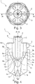
figure 1 is a top view of a first embodiment of an atomizer according to the present invention; -
figure 2 is a front view taken along the A-A plane of the atomizer infigure 1 ; -
figure 3 is a top view of a second embodiment of an atomizer according to the present invention; -
figure 4 is a front view taken along the A-A plane of the atomizer infigure 3 ; and -
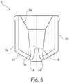
figure 5 is a front section view of a detail of a third embodiment of the atomizer according to the present invention. - With reference to the accompanying figures, numeral 1 indicates an atomizer for liquids according to the present invention.
- In particular, the atomizer 1 comprises at least one
first duct 2, which is configured to convey a flow of liquid to be nebulized. The atomizer 1 further comprises at least onesecond duct 3 configured to convey a flow of gas, typically air. Preferably, the atomizer 1 comprises a plurality of first 2 andsecond ducts 3. More in detail, thefirst duct 2 leads into thesecond duct 3, so as to let the flow of liquid into thesecond duct 3 and mix it with the gas. Thesecond duct 3 has aconverging zone 3a, the function of which is to accelerate the gas flow. Preferably, thefirst duct 2 leads into thesecond duct 3 at theconverging zone 3a. Thefirst duct 2 is connected to thesecond duct 3 at anozzle 10. In particular, such anozzle 10 is placed in theconverging zone 3a of thesecond duct 3. - Preferably, the
first duct 2 is ring-shaped. Furthermore, as shown infigure 2 , the atomizer 1 may comprise aflow guide 19 about which thefirst duct 2 is defined. More than onenozzle 10 are usually present in the preferred embodiments. In particular, there may be two, four or evenmore nozzles 10.Such nozzles 10 are preferably made by milling but they may also be perforations or orifices made in any manner known to the person skilled in the art. - Furthermore, the atomizer 1 has a first abutting
surface 15 placed in thesecond duct 3 and facing thefirst duct 2. Such a first abuttingsurface 15 is configured to receive the flow of liquid and atomize it within thesecond duct 3. In particular, the firstabutting surface 15 is placed at theconverging zone 3a of thesecond duct 3. Advantageously, in this manner, the breakdown of the flow of liquid starts already inside thesecond duct 3. - Further details on the first 2 and
second duct 3 will be provided in a subsequent part of the present description. - More in detail, the atomizer 1 comprises a
main body 5 in which thesecond duct 3 is obtained at least in part. With reference to both embodiments, thesecond duct 3 is ring-shaped. In the preferred embodiments, theduct 3 has a plurality of external openings through which the gas is let in. There may two, four or even more of such openings. Such openings are preferably made by drilling. Furthermore, the openings may have a circular section, but may also have a non-circular section and be made in any manner known to a person skilled in art, e.g. by milling or micro-casting. - More in particular, the
main body 5 has a central axis "C". Preferably, themain body 5 is symmetric with respect to the central axis "C". In other words, themain body 5 develops about the central axis "C". - In further detail, the main body has an
outer side surface 5a. Furthermore, themain body 5 has aninner side surface 5b opposite to theouter side surface 5a. Bothside surfaces figures 2 and4 in particular, theouter side surface 5a is substantially cylinder-shaped. In alternative embodiments (not shown), theouter side surface 5a may have any shape, according to the specific applications. - The mentioned
second duct 3 is defined in part by theinner surface 5b of themain body 5. Such aninner surface 5b is preferably truncated-cone-shaped. With reference tofigure 2 in particular, the inclination of theinner side surface 5b with respect to the central axis "C" is constant. Alternatively, as shown infigure 4 , such an inclination may vary along a direction parallel to the central axis "C". In other words, in the embodiment shown infigure 4 , theinner side surface 5b of themain body 5 is substantially funnel-shaped. It is worth noting that the first abuttingsurface 15, mentioned above, is defined by a portion of theinner side surface 5b of themain body 5. - In an alternative embodiment of the invention, shown in
figure 5 , themain body 5 comprises anouter casing 17 and aninsert 18. In this case, theinner side surface 5b of themain body 5 will be made on theinsert 18, while theouter side surface 5a is defined by theouter casing 17. Advantageously, theinsert 18 may be made of material more resistant to wear, such as ceramic, for example. - The atomizer 1 further comprises a connecting
body 6, associated to themain body 5. Such a connectingbody 6 is configured to be connected to a source of fluid to be nebulized and to a source of gas, neither shown in the accompanying figures. The connecting body has anouter surface 6a and at least a first 6b and a secondinner surface 6c. The outer 6a and inner 6b, 6c surfaces of the connectingbody 6 are developed at least in part along a direction identified by the central axis "C". - In the embodiment shown in
figure 2 , the connectingbody 6 is placed in contact with themain body 5, in particular atrespective interface surfaces main body 5 and the connectingbody 6,such interface surfaces - It is worth noting that the
inner side surface 5b of themain body 5 and the firstinner surface 6b of the connectingbody 6 are reciprocally continuous so as to define thesecond duct 3 in part. - In the embodiment shown in
figure 4 , the atomizer 1 comprises a joiningbody 7 placed between themain body 5 and the connectingbody 6. As the connectingbody 6, the joiningbody 7 also has anouter surface 7a and at least a first 7b and a secondinner surface 7c. More in particular, the firstinner surface 7b joins thefirst surface 6b of the connectingbody 6 to theinner side surface 5b of themain body 5. The secondinner surface 7c of the joiningbody 7 is continuous with the secondinner surface 6c of the connectingbody 6. - The connecting
body 6 further has aseat 8 for thefirst duct 2. In particular, theseat 8 is defined near the central axis "C". With reference to the embodiment infigure 4 , the central seat itself defines thefirst duct 2. Alternatively, as shown infigure 2 , thecentral seat 8 houses aseparate pipe 9 for a flow of liquid to be nebulized. In this case, anouter wall 9a of thepipe 9 also defines thesecond duct 3 in part. - The atomizer 1 further comprises diverting
means 4 which are associated to thefirst duct 3. The diverting means 4 are further configured to divert the flow of liquid coming from thefirst duct 2 and let it into thesecond duct 3. In particular, the divertingmeans 4 are associated to theaforesaid nozzle 10. Such divertingmeans 4 comprise, in particular, acrosswise element 11 which, by intercepting the flow of liquid within thefirst duct 2, diverts it abruptly towards thenozzle 10 and thus into thesecond duct 3. - It is worth noting that, as shown in
figure 2 , the divertingmeans 4 may define a side wall of thesecond duct 3 in part. - With reference to
figure 2 , the divertingmeans 4 comprise a crosswise, preferably disc-shapedbaffle 12, which closes an end of thepipe 9 defining thenozzles 10 in part. In this embodiment, thecrosswise element 11 is thebaffle 12. The fluid is thus forced towards thenozzles 10, which, by being little more than slots, perform a first nebulization of the fluid as the fluid itself is let into in thesecond duct 3. With reference tofigure 4 , theseat 8 has abottom wall 8a, which works as thecrosswise element 11. In this case, thenozzles 10 are defined in the connectingbody 6, in particular between aside wall 8b of theseat 8 and the secondinner surface 6c of the connectingbody 6 itself. - Thus, in this embodiment, the diverting
means 4 comprise thebottom wall 8a of theseat 8, which define a bottom wall of thefirst duct 2. - Furthermore, the atomizer 1 has a mixing
chamber 13. In particular, such achamber 13 is configured to receive a mixture of gas and nebulized liquid from thesecond duct 3. In particular, it is worth noting that thefirst duct 2 does not lead directly into the mixingchamber 13 in the described and illustrated embodiments of the atomizer 1. In other words, the liquid enters into the mixingchamber 13 through thesecond duct 3, in particular at the end of the convergingzone 3a. Consequently, the liquid enters into the mixingchamber 13 already mixed with the gas in part. The turbulent recirculation which is established in the mixingchamber 13 thus performs a further atomization of the fluid. - Advantageously, the atomizer 1 has a second abutting
surface 16 placed within the mixingchamber 13. In particular, the second abuttingsurface 16 faces thesecond duct 3. In this manner, the jet of partially nebulized liquid directly on the second abuttingsurface 16, thus completing the breakdown of the jet of liquid. More in detail, the mixingchamber 13 is defined within themain body 5. More in particular, theinner side surface 5c defines the mixingchamber 13 at least in part. With reference in particular to the embodiment shown infigure 2 , it is worth noting that the divertingmeans 4, in particular thebaffle 12, define the mixingchamber 13 at least in part. - Furthermore, the
chamber 13 has a plurality oforifices 14 to expel the mixture of liquid and gas. The atomization of the liquid is completed during the expulsion through theorifices 14, which in particular are placed at abottom surface 5c of themain body 5.
Claims (11)
- An atomizer (1) for liquids, comprising at least one first duct (2) configured to convey a flow of liquid to be nebulized; at least one second duct (3) configured to convey a flow of gas; a mixing chamber (13) in fluid communication with said second duct (3) and having a plurality of orifices (14) for expelling the nebulized liquid; wherein said atomizer (1) further comprises at least one nozzle (10) placed in said first duct (2) and in fluid communication with said second duct (3) to let said flow of liquid into said second duct (3), said second duct (3) having a first truncated-cone-shaped abutting surface (15) facing said nozzle (10) and configured to receive said flow of liquid and to atomize it in said second duct (3), said first abutting surface (15) being arranged outside said mixing chamber (13), characterized in that said mixing chamber (13) has a truncated-cone-shaped inner surface (5b), the cross section of which is tapered towards said orifices (14), and in that said first abutting surface (15) and said inner surface (5b) of said mixing chamber (13) are continuous to each other.
- An atomizer (1) according to the preceding claim, characterized in that said first abutting surface (15) is inclined with respect to an efflux direction of said nozzle (10).
- An atomizer (1) according to any one of the preceding claims, characterized in that in said second duct (3) has a converging zone (3a) to accelerate said flow of gas.
- An atomizer (1) according to the preceding claim, characterized in that said first abutting surface (15) is placed at said converging zone (3a) of said second duct (3a).
- An atomizer (1) according to the preceding claim, characterized in that said first duct (2) leads into said second duct (3) at said converging zone (3a).
- An atomizer (1) according to any one of the preceding claims, characterized in that said nozzle (10) is placed at said converting zone (3a) of said second duct (3).
- An atomizer (1) according to the preceding claim, characterized in that it comprises a second abutting surface (16) placed inside said mixing chamber (13) and facing said second duct (3).
- An atomizer (1) according to any one of the preceding claims, characterized in that it comprises diverting means (4) associated to said second duct (3) and configured to divert said liquid flow towards the first duct (2), said diverting means (4) defining said mixing chamber (13) at least in part.
- An atomizer (1) according to the preceding claim, characterized in that said diverting means (4) comprise a preferably disc-shaped baffle (12) placed between said first duct (2) and said mixing chamber (13).
- An atomizer (1) according to claim 8 or 9, characterized in that said diverting means (4) comprise a bottom wall (8a) of the first duct (2).
- An atomizer (1) according to any one of claims from 8 to 10, characterized in that said diverting means (4) define partially a side wall of the second duct (3).
Priority Applications (1)
| Application Number | Priority Date | Filing Date | Title |
|---|---|---|---|
| EP14190895.4A EP3015173B1 (en) | 2014-10-29 | 2014-10-29 | Internal mix air atomizing spray nozzle |
Applications Claiming Priority (1)
| Application Number | Priority Date | Filing Date | Title |
|---|---|---|---|
| EP14190895.4A EP3015173B1 (en) | 2014-10-29 | 2014-10-29 | Internal mix air atomizing spray nozzle |
Publications (2)
| Publication Number | Publication Date |
|---|---|
| EP3015173A1 EP3015173A1 (en) | 2016-05-04 |
| EP3015173B1 true EP3015173B1 (en) | 2017-09-06 |
Family
ID=52103200
Family Applications (1)
| Application Number | Title | Priority Date | Filing Date |
|---|---|---|---|
| EP14190895.4A Revoked EP3015173B1 (en) | 2014-10-29 | 2014-10-29 | Internal mix air atomizing spray nozzle |
Country Status (1)
| Country | Link |
|---|---|
| EP (1) | EP3015173B1 (en) |
Families Citing this family (1)
| Publication number | Priority date | Publication date | Assignee | Title |
|---|---|---|---|---|
| US11541406B2 (en) | 2020-03-30 | 2023-01-03 | Medmix Switzerland Ag | Spray nozzle |
Citations (4)
| Publication number | Priority date | Publication date | Assignee | Title |
|---|---|---|---|---|
| US5553785A (en) | 1995-01-10 | 1996-09-10 | Spraying Systems Co. | Enhanced efficiency apparatus for atomizing and spraying liquid |
| WO2003095097A1 (en) | 2002-05-07 | 2003-11-20 | Spraying Systems Co. | Internal mix air atomizing spray nozzle assembly |
| DE10319582B4 (en) | 2003-04-24 | 2007-03-22 | Lechler Gmbh | Binary spray nozzle |
| DE102009037828A1 (en) | 2008-11-11 | 2010-05-20 | Wurz, Dieter, Prof. Dr. | Two-fluid nozzle, bundling nozzle and method for atomizing fluids |
Family Cites Families (8)
| Publication number | Priority date | Publication date | Assignee | Title |
|---|---|---|---|---|
| US4708293A (en) | 1983-02-24 | 1987-11-24 | Enel-Ente Nazionale Per L'energia Elettrica | Atomizer for viscous liquid fuels |
| US4699587A (en) | 1985-05-23 | 1987-10-13 | Ishikawajima-Harima Jukogyo Kabushiki Kaisha | Burner |
| DE3669915D1 (en) | 1986-11-27 | 1990-05-03 | Fluidics Instr Bv | COMPRESSED AIR SPRAYER. |
| EP0278115B1 (en) | 1987-02-13 | 1990-04-11 | BBC Brown Boveri AG | Spray nozzle |
| US4982716A (en) | 1988-02-19 | 1991-01-08 | Toyota Jidosha Kabushiki Kaisha | Fuel injection valve with an air assist adapter for an internal combustion engine |
| US5732885A (en) * | 1994-10-07 | 1998-03-31 | Spraying Systems Co. | Internal mix air atomizing spray nozzle |
| HUE031504T2 (en) | 2004-08-23 | 2017-07-28 | Spraying Systems Co | Improved internal mix air atomizing nozzle assembly |
| CN101233078B (en) * | 2005-06-02 | 2013-02-27 | Mecs公司 | Process and apparatus for the combustion of a sulfur-containing liquid |
-
2014
- 2014-10-29 EP EP14190895.4A patent/EP3015173B1/en not_active Revoked
Patent Citations (4)
| Publication number | Priority date | Publication date | Assignee | Title |
|---|---|---|---|---|
| US5553785A (en) | 1995-01-10 | 1996-09-10 | Spraying Systems Co. | Enhanced efficiency apparatus for atomizing and spraying liquid |
| WO2003095097A1 (en) | 2002-05-07 | 2003-11-20 | Spraying Systems Co. | Internal mix air atomizing spray nozzle assembly |
| DE10319582B4 (en) | 2003-04-24 | 2007-03-22 | Lechler Gmbh | Binary spray nozzle |
| DE102009037828A1 (en) | 2008-11-11 | 2010-05-20 | Wurz, Dieter, Prof. Dr. | Two-fluid nozzle, bundling nozzle and method for atomizing fluids |
Also Published As
| Publication number | Publication date |
|---|---|
| EP3015173A1 (en) | 2016-05-04 |
Similar Documents
| Publication | Publication Date | Title |
|---|---|---|
| EP2739400B1 (en) | Pressurized air assisted spray nozzle assembly | |
| CN105008054B (en) | Atomizer for sanitary outlet device and the sanitary outlet fitting with discharging device | |
| CN100571890C (en) | Improved internal mix air atomizing nozzle assembly | |
| CN106984459B (en) | Spraying device | |
| CN107398362B (en) | Nozzle for spraying liquid | |
| CN101080255B (en) | Method and nozzle for spraying medium | |
| JP2010247133A (en) | Two-fluid nozzle | |
| CN105772264B (en) | Method for producing a jet of spray, and two-component nozzle | |
| JP6350951B2 (en) | Spraying equipment | |
| CN102836508A (en) | Foam generating device for fire hose | |
| JP6159711B2 (en) | Liquid ejecting apparatus and liquid ejecting method | |
| JP2016087575A (en) | Spray nozzle | |
| EP3015173B1 (en) | Internal mix air atomizing spray nozzle | |
| RU2500482C1 (en) | Centrifugal wide-fan sprayer | |
| KR101732648B1 (en) | A Nozzle Assembly for Atomizing Liquid | |
| CN107199136A (en) | Sprayer unit | |
| CN105251167A (en) | High-efficiency two-phase flow atomizer | |
| RU2383820C1 (en) | Wide-flame centrodugal nozzle | |
| JP4266239B1 (en) | Two-fluid atomizing nozzle | |
| RU2383821C1 (en) | Wide-flame centrodugal nozzle | |
| CN207913976U (en) | Improved structure of atomizing nozzle | |
| JP2009061362A (en) | Nozzle for painting | |
| KR20190138679A (en) | Fluid Nozzle for Fine Bubble Injection | |
| KR101464221B1 (en) | Liquid injection device | |
| RU171370U1 (en) | NOZZLE |
Legal Events
| Date | Code | Title | Description |
|---|---|---|---|
| PUAI | Public reference made under article 153(3) epc to a published international application that has entered the european phase |
Free format text: ORIGINAL CODE: 0009012 |
|
| AK | Designated contracting states |
Kind code of ref document: A1 Designated state(s): AL AT BE BG CH CY CZ DE DK EE ES FI FR GB GR HR HU IE IS IT LI LT LU LV MC MK MT NL NO PL PT RO RS SE SI SK SM TR |
|
| AX | Request for extension of the european patent |
Extension state: BA ME |
|
| STAA | Information on the status of an ep patent application or granted ep patent |
Free format text: STATUS: REQUEST FOR EXAMINATION WAS MADE |
|
| 17P | Request for examination filed |
Effective date: 20161103 |
|
| RBV | Designated contracting states (corrected) |
Designated state(s): AL AT BE BG CH CY CZ DE DK EE ES FI FR GB GR HR HU IE IS IT LI LT LU LV MC MK MT NL NO PL PT RO RS SE SI SK SM TR |
|
| RIC1 | Information provided on ipc code assigned before grant |
Ipc: B05B 7/04 20060101AFI20170131BHEP |
|
| GRAP | Despatch of communication of intention to grant a patent |
Free format text: ORIGINAL CODE: EPIDOSNIGR1 |
|
| STAA | Information on the status of an ep patent application or granted ep patent |
Free format text: STATUS: GRANT OF PATENT IS INTENDED |
|
| INTG | Intention to grant announced |
Effective date: 20170328 |
|
| GRAS | Grant fee paid |
Free format text: ORIGINAL CODE: EPIDOSNIGR3 |
|
| GRAA | (expected) grant |
Free format text: ORIGINAL CODE: 0009210 |
|
| STAA | Information on the status of an ep patent application or granted ep patent |
Free format text: STATUS: THE PATENT HAS BEEN GRANTED |
|
| AK | Designated contracting states |
Kind code of ref document: B1 Designated state(s): AL AT BE BG CH CY CZ DE DK EE ES FI FR GB GR HR HU IE IS IT LI LT LU LV MC MK MT NL NO PL PT RO RS SE SI SK SM TR |
|
| REG | Reference to a national code |
Ref country code: GB Ref legal event code: FG4D |
|
| REG | Reference to a national code |
Ref country code: CH Ref legal event code: EP Ref country code: AT Ref legal event code: REF Ref document number: 925289 Country of ref document: AT Kind code of ref document: T Effective date: 20170915 |
|
| REG | Reference to a national code |
Ref country code: IE Ref legal event code: FG4D |
|
| REG | Reference to a national code |
Ref country code: DE Ref legal event code: R096 Ref document number: 602014014096 Country of ref document: DE |
|
| REG | Reference to a national code |
Ref country code: FR Ref legal event code: PLFP Year of fee payment: 4 |
|
| REG | Reference to a national code |
Ref country code: NL Ref legal event code: MP Effective date: 20170906 |
|
| REG | Reference to a national code |
Ref country code: LT Ref legal event code: MG4D |
|
| PG25 | Lapsed in a contracting state [announced via postgrant information from national office to epo] |
Ref country code: HR Free format text: LAPSE BECAUSE OF FAILURE TO SUBMIT A TRANSLATION OF THE DESCRIPTION OR TO PAY THE FEE WITHIN THE PRESCRIBED TIME-LIMIT Effective date: 20170906 Ref country code: LT Free format text: LAPSE BECAUSE OF FAILURE TO SUBMIT A TRANSLATION OF THE DESCRIPTION OR TO PAY THE FEE WITHIN THE PRESCRIBED TIME-LIMIT Effective date: 20170906 Ref country code: FI Free format text: LAPSE BECAUSE OF FAILURE TO SUBMIT A TRANSLATION OF THE DESCRIPTION OR TO PAY THE FEE WITHIN THE PRESCRIBED TIME-LIMIT Effective date: 20170906 Ref country code: NO Free format text: LAPSE BECAUSE OF FAILURE TO SUBMIT A TRANSLATION OF THE DESCRIPTION OR TO PAY THE FEE WITHIN THE PRESCRIBED TIME-LIMIT Effective date: 20171206 Ref country code: SE Free format text: LAPSE BECAUSE OF FAILURE TO SUBMIT A TRANSLATION OF THE DESCRIPTION OR TO PAY THE FEE WITHIN THE PRESCRIBED TIME-LIMIT Effective date: 20170906 |
|
| REG | Reference to a national code |
Ref country code: AT Ref legal event code: MK05 Ref document number: 925289 Country of ref document: AT Kind code of ref document: T Effective date: 20170906 |
|
| PG25 | Lapsed in a contracting state [announced via postgrant information from national office to epo] |
Ref country code: LV Free format text: LAPSE BECAUSE OF FAILURE TO SUBMIT A TRANSLATION OF THE DESCRIPTION OR TO PAY THE FEE WITHIN THE PRESCRIBED TIME-LIMIT Effective date: 20170906 Ref country code: ES Free format text: LAPSE BECAUSE OF FAILURE TO SUBMIT A TRANSLATION OF THE DESCRIPTION OR TO PAY THE FEE WITHIN THE PRESCRIBED TIME-LIMIT Effective date: 20170906 Ref country code: GR Free format text: LAPSE BECAUSE OF FAILURE TO SUBMIT A TRANSLATION OF THE DESCRIPTION OR TO PAY THE FEE WITHIN THE PRESCRIBED TIME-LIMIT Effective date: 20171207 Ref country code: RS Free format text: LAPSE BECAUSE OF FAILURE TO SUBMIT A TRANSLATION OF THE DESCRIPTION OR TO PAY THE FEE WITHIN THE PRESCRIBED TIME-LIMIT Effective date: 20170906 Ref country code: BG Free format text: LAPSE BECAUSE OF FAILURE TO SUBMIT A TRANSLATION OF THE DESCRIPTION OR TO PAY THE FEE WITHIN THE PRESCRIBED TIME-LIMIT Effective date: 20171206 |
|
| PG25 | Lapsed in a contracting state [announced via postgrant information from national office to epo] |
Ref country code: NL Free format text: LAPSE BECAUSE OF FAILURE TO SUBMIT A TRANSLATION OF THE DESCRIPTION OR TO PAY THE FEE WITHIN THE PRESCRIBED TIME-LIMIT Effective date: 20170906 |
|
| PG25 | Lapsed in a contracting state [announced via postgrant information from national office to epo] |
Ref country code: PL Free format text: LAPSE BECAUSE OF FAILURE TO SUBMIT A TRANSLATION OF THE DESCRIPTION OR TO PAY THE FEE WITHIN THE PRESCRIBED TIME-LIMIT Effective date: 20170906 Ref country code: CZ Free format text: LAPSE BECAUSE OF FAILURE TO SUBMIT A TRANSLATION OF THE DESCRIPTION OR TO PAY THE FEE WITHIN THE PRESCRIBED TIME-LIMIT Effective date: 20170906 Ref country code: RO Free format text: LAPSE BECAUSE OF FAILURE TO SUBMIT A TRANSLATION OF THE DESCRIPTION OR TO PAY THE FEE WITHIN THE PRESCRIBED TIME-LIMIT Effective date: 20170906 |
|
| PG25 | Lapsed in a contracting state [announced via postgrant information from national office to epo] |
Ref country code: AT Free format text: LAPSE BECAUSE OF FAILURE TO SUBMIT A TRANSLATION OF THE DESCRIPTION OR TO PAY THE FEE WITHIN THE PRESCRIBED TIME-LIMIT Effective date: 20170906 Ref country code: IS Free format text: LAPSE BECAUSE OF FAILURE TO SUBMIT A TRANSLATION OF THE DESCRIPTION OR TO PAY THE FEE WITHIN THE PRESCRIBED TIME-LIMIT Effective date: 20180106 Ref country code: SM Free format text: LAPSE BECAUSE OF FAILURE TO SUBMIT A TRANSLATION OF THE DESCRIPTION OR TO PAY THE FEE WITHIN THE PRESCRIBED TIME-LIMIT Effective date: 20170906 Ref country code: SK Free format text: LAPSE BECAUSE OF FAILURE TO SUBMIT A TRANSLATION OF THE DESCRIPTION OR TO PAY THE FEE WITHIN THE PRESCRIBED TIME-LIMIT Effective date: 20170906 Ref country code: EE Free format text: LAPSE BECAUSE OF FAILURE TO SUBMIT A TRANSLATION OF THE DESCRIPTION OR TO PAY THE FEE WITHIN THE PRESCRIBED TIME-LIMIT Effective date: 20170906 |
|
| REG | Reference to a national code |
Ref country code: CH Ref legal event code: PL |
|
| REG | Reference to a national code |
Ref country code: DE Ref legal event code: R026 Ref document number: 602014014096 Country of ref document: DE |
|
| PLBI | Opposition filed |
Free format text: ORIGINAL CODE: 0009260 |
|
| PLAX | Notice of opposition and request to file observation + time limit sent |
Free format text: ORIGINAL CODE: EPIDOSNOBS2 |
|
| PG25 | Lapsed in a contracting state [announced via postgrant information from national office to epo] |
Ref country code: MC Free format text: LAPSE BECAUSE OF FAILURE TO SUBMIT A TRANSLATION OF THE DESCRIPTION OR TO PAY THE FEE WITHIN THE PRESCRIBED TIME-LIMIT Effective date: 20170906 |
|
| 26 | Opposition filed |
Opponent name: LECHLER GMBH Effective date: 20180605 |
|
| REG | Reference to a national code |
Ref country code: IE Ref legal event code: MM4A |
|
| PG25 | Lapsed in a contracting state [announced via postgrant information from national office to epo] |
Ref country code: LU Free format text: LAPSE BECAUSE OF NON-PAYMENT OF DUE FEES Effective date: 20171029 Ref country code: DK Free format text: LAPSE BECAUSE OF FAILURE TO SUBMIT A TRANSLATION OF THE DESCRIPTION OR TO PAY THE FEE WITHIN THE PRESCRIBED TIME-LIMIT Effective date: 20170906 Ref country code: LI Free format text: LAPSE BECAUSE OF NON-PAYMENT OF DUE FEES Effective date: 20171031 Ref country code: CH Free format text: LAPSE BECAUSE OF NON-PAYMENT OF DUE FEES Effective date: 20171031 |
|
| REG | Reference to a national code |
Ref country code: BE Ref legal event code: MM Effective date: 20171031 |
|
| PG25 | Lapsed in a contracting state [announced via postgrant information from national office to epo] |
Ref country code: SI Free format text: LAPSE BECAUSE OF FAILURE TO SUBMIT A TRANSLATION OF THE DESCRIPTION OR TO PAY THE FEE WITHIN THE PRESCRIBED TIME-LIMIT Effective date: 20170906 Ref country code: BE Free format text: LAPSE BECAUSE OF NON-PAYMENT OF DUE FEES Effective date: 20171031 |
|
| REG | Reference to a national code |
Ref country code: FR Ref legal event code: PLFP Year of fee payment: 5 |
|
| PG25 | Lapsed in a contracting state [announced via postgrant information from national office to epo] |
Ref country code: MT Free format text: LAPSE BECAUSE OF NON-PAYMENT OF DUE FEES Effective date: 20171029 |
|
| PLBB | Reply of patent proprietor to notice(s) of opposition received |
Free format text: ORIGINAL CODE: EPIDOSNOBS3 |
|
| PG25 | Lapsed in a contracting state [announced via postgrant information from national office to epo] |
Ref country code: IE Free format text: LAPSE BECAUSE OF NON-PAYMENT OF DUE FEES Effective date: 20171029 |
|
| GBPC | Gb: european patent ceased through non-payment of renewal fee |
Effective date: 20181029 |
|
| PG25 | Lapsed in a contracting state [announced via postgrant information from national office to epo] |
Ref country code: HU Free format text: LAPSE BECAUSE OF FAILURE TO SUBMIT A TRANSLATION OF THE DESCRIPTION OR TO PAY THE FEE WITHIN THE PRESCRIBED TIME-LIMIT; INVALID AB INITIO Effective date: 20141029 |
|
| PG25 | Lapsed in a contracting state [announced via postgrant information from national office to epo] |
Ref country code: CY Free format text: LAPSE BECAUSE OF FAILURE TO SUBMIT A TRANSLATION OF THE DESCRIPTION OR TO PAY THE FEE WITHIN THE PRESCRIBED TIME-LIMIT Effective date: 20170906 Ref country code: GB Free format text: LAPSE BECAUSE OF NON-PAYMENT OF DUE FEES Effective date: 20181029 |
|
| PG25 | Lapsed in a contracting state [announced via postgrant information from national office to epo] |
Ref country code: MK Free format text: LAPSE BECAUSE OF FAILURE TO SUBMIT A TRANSLATION OF THE DESCRIPTION OR TO PAY THE FEE WITHIN THE PRESCRIBED TIME-LIMIT Effective date: 20170906 |
|
| RDAF | Communication despatched that patent is revoked |
Free format text: ORIGINAL CODE: EPIDOSNREV1 |
|
| APBM | Appeal reference recorded |
Free format text: ORIGINAL CODE: EPIDOSNREFNO |
|
| APBP | Date of receipt of notice of appeal recorded |
Free format text: ORIGINAL CODE: EPIDOSNNOA2O |
|
| APAH | Appeal reference modified |
Free format text: ORIGINAL CODE: EPIDOSCREFNO |
|
| PG25 | Lapsed in a contracting state [announced via postgrant information from national office to epo] |
Ref country code: TR Free format text: LAPSE BECAUSE OF FAILURE TO SUBMIT A TRANSLATION OF THE DESCRIPTION OR TO PAY THE FEE WITHIN THE PRESCRIBED TIME-LIMIT Effective date: 20170906 |
|
| APBQ | Date of receipt of statement of grounds of appeal recorded |
Free format text: ORIGINAL CODE: EPIDOSNNOA3O |
|
| PG25 | Lapsed in a contracting state [announced via postgrant information from national office to epo] |
Ref country code: PT Free format text: LAPSE BECAUSE OF FAILURE TO SUBMIT A TRANSLATION OF THE DESCRIPTION OR TO PAY THE FEE WITHIN THE PRESCRIBED TIME-LIMIT Effective date: 20170906 |
|
| APBY | Invitation to file observations in appeal sent |
Free format text: ORIGINAL CODE: EPIDOSNOBA2O |
|
| APCA | Receipt of observations in appeal recorded |
Free format text: ORIGINAL CODE: EPIDOSNOBA4O |
|
| PG25 | Lapsed in a contracting state [announced via postgrant information from national office to epo] |
Ref country code: AL Free format text: LAPSE BECAUSE OF FAILURE TO SUBMIT A TRANSLATION OF THE DESCRIPTION OR TO PAY THE FEE WITHIN THE PRESCRIBED TIME-LIMIT Effective date: 20170906 |
|
| PGFP | Annual fee paid to national office [announced via postgrant information from national office to epo] |
Ref country code: DE Payment date: 20211019 Year of fee payment: 8 |
|
| PGFP | Annual fee paid to national office [announced via postgrant information from national office to epo] |
Ref country code: IT Payment date: 20211025 Year of fee payment: 8 Ref country code: FR Payment date: 20211029 Year of fee payment: 8 |
|
| REG | Reference to a national code |
Ref country code: DE Ref legal event code: R103 Ref document number: 602014014096 Country of ref document: DE Ref country code: DE Ref legal event code: R064 Ref document number: 602014014096 Country of ref document: DE |
|
| APBU | Appeal procedure closed |
Free format text: ORIGINAL CODE: EPIDOSNNOA9O |
|
| RDAG | Patent revoked |
Free format text: ORIGINAL CODE: 0009271 |
|
| STAA | Information on the status of an ep patent application or granted ep patent |
Free format text: STATUS: PATENT REVOKED |
|
| REG | Reference to a national code |
Ref country code: FI Ref legal event code: MGE |
|
| 27W | Patent revoked |
Effective date: 20220518 |