EP3014964B1 - Rrh concealment module/methods in natural convection - Google Patents
Rrh concealment module/methods in natural convection Download PDFInfo
- Publication number
- EP3014964B1 EP3014964B1 EP14816569.9A EP14816569A EP3014964B1 EP 3014964 B1 EP3014964 B1 EP 3014964B1 EP 14816569 A EP14816569 A EP 14816569A EP 3014964 B1 EP3014964 B1 EP 3014964B1
- Authority
- EP
- European Patent Office
- Prior art keywords
- remote radio
- air
- radio head
- baffle
- rrh
- Prior art date
- Legal status (The legal status is an assumption and is not a legal conclusion. Google has not performed a legal analysis and makes no representation as to the accuracy of the status listed.)
- Not-in-force
Links
- 238000000034 method Methods 0.000 title description 3
- 238000001816 cooling Methods 0.000 claims description 12
- 239000004020 conductor Substances 0.000 claims 1
- 238000009423 ventilation Methods 0.000 description 13
- 230000000740 bleeding effect Effects 0.000 description 2
- 238000013316 zoning Methods 0.000 description 2
- 241000238631 Hexapoda Species 0.000 description 1
- 230000005540 biological transmission Effects 0.000 description 1
- 230000003247 decreasing effect Effects 0.000 description 1
- 238000011161 development Methods 0.000 description 1
- 230000018109 developmental process Effects 0.000 description 1
- 238000009434 installation Methods 0.000 description 1
- 238000013021 overheating Methods 0.000 description 1
Images

Classifications
-
- H—ELECTRICITY
- H01—ELECTRIC ELEMENTS
- H01Q—ANTENNAS, i.e. RADIO AERIALS
- H01Q1/00—Details of, or arrangements associated with, antennas
- H01Q1/12—Supports; Mounting means
- H01Q1/22—Supports; Mounting means by structural association with other equipment or articles
- H01Q1/24—Supports; Mounting means by structural association with other equipment or articles with receiving set
- H01Q1/241—Supports; Mounting means by structural association with other equipment or articles with receiving set used in mobile communications, e.g. GSM
- H01Q1/246—Supports; Mounting means by structural association with other equipment or articles with receiving set used in mobile communications, e.g. GSM specially adapted for base stations
-
- H—ELECTRICITY
- H01—ELECTRIC ELEMENTS
- H01Q—ANTENNAS, i.e. RADIO AERIALS
- H01Q1/00—Details of, or arrangements associated with, antennas
- H01Q1/02—Arrangements for de-icing; Arrangements for drying-out ; Arrangements for cooling; Arrangements for preventing corrosion
-
- H—ELECTRICITY
- H05—ELECTRIC TECHNIQUES NOT OTHERWISE PROVIDED FOR
- H05K—PRINTED CIRCUITS; CASINGS OR CONSTRUCTIONAL DETAILS OF ELECTRIC APPARATUS; MANUFACTURE OF ASSEMBLAGES OF ELECTRICAL COMPONENTS
- H05K7/00—Constructional details common to different types of electric apparatus
- H05K7/20—Modifications to facilitate cooling, ventilating, or heating
- H05K7/20009—Modifications to facilitate cooling, ventilating, or heating using a gaseous coolant in electronic enclosures
- H05K7/20127—Natural convection
Definitions
- a wireless radio network system consists of a base band unit (BBU), a remote radio head (RRH or sometimes referred to as RRU) and an antenna.
- BBU base band unit
- RRH remote radio head
- RRU remote radio head
- RRH orientation also plays a large role in proper cooling.
- RRHs When RRHs are placed inside a concealment, they are typically not positioned to ensure that the RRHs dissipated heat does not flow from one RRH into the cooling air of another RRH.
- US 2012/196522 A1 may be considered prior art and relates to a structure for protecting a Radio Frequency Remote Head.
- the structure includes a solar head and a solar body.
- An upper side of the solar head is sloped to prevent an inflow of rainwater and has at least one solar panel, and a lower side thereof has at least one round cable hole surrounded by a rubber material.
- the solar body is situated on a lower end of the solar head and includes a plurality of solar panels, a side of each of which is sloped to prevent an inflow of rainwater and is openable upward.
- An upper end of the solar body has an air outlet formed to exhaust air, and a lower end thereof has an air inlet formed to receive air.
- the air outlet and the air inlet each have a plurality of supports arranged at specific intervals and connected by a protection net.
- One way to overcome the limitations of concealing RRHs or any active heat generating components is to ensure proper ventilation, air-flow direction, and equipment orientation.
- One aspect of this invention relates to concealing groups of RRHs or radio modules inside a single concealed compartment. Multiple groups of RRH can be concealed using proper spacing and orientation.
- the concealment panels have optimized ventilation areas to allow proper inlet and outlet air flow and cooling.
- the ventilation panels have associated baffle components to ensure that all air is flowing over the heat generating equipment.
- the equipment is also orientated so that the exhaust air that has been heated does not flow into the ventilation panels of adjacent equipment.
- the RRH modules are enclosed behind optimized ventilation panels.
- the panels contain strategically sized openings to provide maximum open area, best manufacturability, insect resistance, and clog resistance.
- the ventilation patterns are created in pairs for each RRH module. One set of ventilation patterns below the RRH for inlet air flow and a second set of ventilation patterns above the RRH to exhaust the heated air.
- the ventilation patterns are optimized to prevent heated air from bleeding into the ventilation area of an adjacent RRH module.
- air baffling is required to prevent cool air from bleeding off into other areas within the concealment.
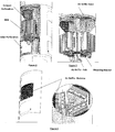
- Second, the mounting bracket that mounts the RRH to the pole is configured to also force air over the back of the RRH and any associated heatsink fins (Air Baffle-Bracket). The lower edge of the mounting bracket may cooperate with the baffle plate to direct airflow.
- baffle that closes off the inside of the radome and fills the gap between the radome and the RRH (Air Baffle-Radome).
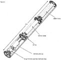
- This baffle may be constructed out of a thermally conducive material that would allow the conduction of heat away from the RRH to the outside surface offering and additional cooling technique. (See Figures 2,3,4 )
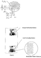
- each grouping of RRHs are equally spaced and assembled within a round concealed compartment. For example, if there are (3) RRH in a grouping, each RRH is angularly spaced 120 degrees from each other within the module.
- the RRHs When stacking a second set of RRH above the first set or module, the RRHs would follow the same angular spacing as the module below, but the entire module would be rotated 1 ⁇ 2 the angular spacing of the RRHs. In this example the top module would be rotated 60 degrees from the module below. This same formula would apply regardless of the number of RRHs assembled and regardless of the number groupings of RRUs. (See Figure 5 ).
Landscapes
- Engineering & Computer Science (AREA)
- Microelectronics & Electronic Packaging (AREA)
- Computer Networks & Wireless Communication (AREA)
- Physics & Mathematics (AREA)
- Thermal Sciences (AREA)
- Cooling Or The Like Of Electrical Apparatus (AREA)
- Signal Processing (AREA)
Description
- A wireless radio network system consists of a base band unit (BBU), a remote radio head (RRH or sometimes referred to as RRU) and an antenna. As more wireless capacity is required, additional wireless sites are necessary to handle the ever-growing need for additional bandwidth and coverage. As these wireless sites move closer to urban areas and within municipalities, hiding or concealing this network equipment is often preferred. In many cases local zoning regulations require the concealment of said equipment. This concealment becomes a challenge for any active components that are generating heat. This is especially true for the remote radio head (RRH) modules, the device that broadcasts the radio frequency signal in a wireless system. These devices require adequate cooling and ventilation to operate properly. Note: In this invention the BBU is considered to be located somewhere outside of the concealment, not at the top of the tower. If the BBU is joined with the RRH it would be considered to be part of the RRH and viewed as the same module.
- Current Concealment methods do not provide adequate cooling. When RRHs are placed inside a concealment, there are usually very little or no openings in the concealment radome to provide adequate ventilation. In instances where there are openings in the concealment radomes, they are typically too small and located below the RRHs with no exhaust vents to allow the heated air to be released. This lack of proper ventilation and airflow will result in the overheating of the RRHs, and a shortened product life.
- RRH orientation also plays a large role in proper cooling. When RRHs are placed inside a concealment, they are typically not positioned to ensure that the RRHs dissipated heat does not flow from one RRH into the cooling air of another RRH.
- Currently known strategies to cope with inadequate cooling have performance and cost disadvantages. With current concealed solutions not providing adequate cooling, the RRHs are often placed at ground level or outside of the concealment module. Such ground installations result in higher power consumption and energy costs, as well as decreased performance due to the transmission losses from long RP jumper cables connecting the RRHs to the antennas at the top of the tower. Additional real estate is also needed to mount the RRHs when placed at ground level. When RRHs are placed outside of the concealment module but still on the tower structure, the RRHs lose the aesthetic advantages of concealment and often violate zoning requirements.
- There are also issues with accessibility. Most concealment modules are large, long cylinders. Accessing the equipment within the concealment becomes difficult as the entire cylinder must be removed. These concealment cylinders are often very heavy and require a mechanical advantage to be removed.
-
US 2012/196522 A1 may be considered prior art and relates to a structure for protecting a Radio Frequency Remote Head. The structure includes a solar head and a solar body. An upper side of the solar head is sloped to prevent an inflow of rainwater and has at least one solar panel, and a lower side thereof has at least one round cable hole surrounded by a rubber material. The solar body is situated on a lower end of the solar head and includes a plurality of solar panels, a side of each of which is sloped to prevent an inflow of rainwater and is openable upward. An upper end of the solar body has an air outlet formed to exhaust air, and a lower end thereof has an air inlet formed to receive air. The air outlet and the air inlet each have a plurality of supports arranged at specific intervals and connected by a protection net. - According to the invention, the problem is solved by the subject-matter outlined in the independent claim. Advantageous further developments of the invention are set forth in the subclaims.
- One way to overcome the limitations of concealing RRHs or any active heat generating components is to ensure proper ventilation, air-flow direction, and equipment orientation. One aspect of this invention relates to concealing groups of RRHs or radio modules inside a single concealed compartment. Multiple groups of RRH can be concealed using proper spacing and orientation.
- The concealment panels have optimized ventilation areas to allow proper inlet and outlet air flow and cooling. The ventilation panels have associated baffle components to ensure that all air is flowing over the heat generating equipment. The equipment is also orientated so that the exhaust air that has been heated does not flow into the ventilation panels of adjacent equipment.
- The RRH modules are enclosed behind optimized ventilation panels. The panels contain strategically sized openings to provide maximum open area, best manufacturability, insect resistance, and clog resistance. The ventilation patterns are created in pairs for each RRH module. One set of ventilation patterns below the RRH for inlet air flow and a second set of ventilation patterns above the RRH to exhaust the heated air. The ventilation patterns are optimized to prevent heated air from bleeding into the ventilation area of an adjacent RRH module.
- In order to achieve proper air flow velocity over a concealed RRH, air baffling is required to prevent cool air from bleeding off into other areas within the concealment. In this invention, there may be (4) components to the airflow baffling. First, there is a baffle plate which is under the RRH and blocks any airflow from going around the pole (Air Baffle-Pole). Second, the mounting bracket that mounts the RRH to the pole is configured to also force air over the back of the RRH and any associated heatsink fins (Air Baffle-Bracket). The lower edge of the mounting bracket may cooperate with the baffle plate to direct airflow. Third, there is an air baffle hood that forces the air out the exhaust perforation (Air Baffle-Hood). Forth, there is a baffle that closes off the inside of the radome and fills the gap between the radome and the RRH (Air Baffle-Radome). This baffle may be constructed out of a thermally conducive material that would allow the conduction of heat away from the RRH to the outside surface offering and additional cooling technique. (See
Figures 2,3,4 ) - Once proper airflow is generated for each RRH module, the RRHs should be orientated so that the hot air exiting the exhaust perforation of one RRH module does not enter the inlet perforation of another RRH module. This is very important when stacking multiple configurations of RRHs. In this invention, each grouping of RRHs are equally spaced and assembled within a round concealed compartment. For example, if there are (3) RRH in a grouping, each RRH is angularly spaced 120 degrees from each other within the module. When stacking a second set of RRH above the first set or module, the RRHs would follow the same angular spacing as the module below, but the entire module would be rotated ½ the angular spacing of the RRHs. In this example the top module would be rotated 60 degrees from the module below. This same formula would apply regardless of the number of RRHs assembled and regardless of the number groupings of RRUs. (See
Figure 5 ).
Claims (4)
- An apparatus comprising:An enclosure forming a concealment module, the concealment module including an air inlet panel and an air outlet panel, the air outlet panel located higher than the air inlet panel;a remote radio head having a front side and a back side, the remote radio head being disposed with the concealment module, and being mounted on a support, and located between the air inlet panel and the air outlet panel;a first baffle, located under the remote radio head to prevent cool air from the air inlet panel from being diverted to a space between the remote radio head and the support;a second baffle, located at the back of the remote radio head to direct cooling air over the back of the remote radio head;a third baffle, located on top of the remote radio head to direct heated cooling air to the air outlet panel; anda fourth baffle, located within the enclosure to direct cooling air over the front of the remote radio head wherein the air inlet panel, the air outlet panel and the first, second, third and fourth baffles provide a natural convection path for the air for cooling the remote radio head.
- The apparatus of claim 1, wherein the second baffle further comprises a bracket for mounting the remote radio head to the support.
- The apparatus of claim 1, wherein the fourth baffle further comprises a thermally conductive material, and thermally couples heatsink fins on the front of the remote radio head to the concealment module.
- The apparatus of claim 1, wherein the concealment module includes a plurality of air inlet panels and a plurality of air outlet panels, the apparatus further comprising:a.a plurality of remote radio heads disposed with the concealment module;b.a plurality of second baffles, each associated with one of the plurality of remote radio heads;c. a plurality of third baffles, each associated with one of the plurality of remote radio heads and one of the plurality of air outlet panels;d. a plurality of fourth baffles, each associated with one of the plurality of remote radio heads;
Priority Applications (1)
| Application Number | Priority Date | Filing Date | Title |
|---|---|---|---|
| PL14816569T PL3014964T3 (en) | 2013-06-28 | 2014-06-12 | Rrh concealment module/methods in natural convection |
Applications Claiming Priority (2)
| Application Number | Priority Date | Filing Date | Title |
|---|---|---|---|
| US201361840763P | 2013-06-28 | 2013-06-28 | |
| PCT/US2014/042118 WO2014209625A1 (en) | 2013-06-28 | 2014-06-12 | Rrh concealment module/methods in natural convection |
Publications (3)
| Publication Number | Publication Date |
|---|---|
| EP3014964A1 EP3014964A1 (en) | 2016-05-04 |
| EP3014964A4 EP3014964A4 (en) | 2017-02-22 |
| EP3014964B1 true EP3014964B1 (en) | 2019-03-13 |
Family
ID=52142558
Family Applications (1)
| Application Number | Title | Priority Date | Filing Date |
|---|---|---|---|
| EP14816569.9A Not-in-force EP3014964B1 (en) | 2013-06-28 | 2014-06-12 | Rrh concealment module/methods in natural convection |
Country Status (5)
| Country | Link |
|---|---|
| US (1) | US9287613B2 (en) |
| EP (1) | EP3014964B1 (en) |
| ES (1) | ES2725878T3 (en) |
| PL (1) | PL3014964T3 (en) |
| WO (1) | WO2014209625A1 (en) |
Families Citing this family (15)
| Publication number | Priority date | Publication date | Assignee | Title |
|---|---|---|---|---|
| EP3033805B1 (en) * | 2013-08-16 | 2017-05-24 | CommScope Technologies LLC | Modular small cell base station architecture |
| KR102140293B1 (en) * | 2014-02-24 | 2020-08-11 | 주식회사 케이엠더블유 | Multi band antenna device |
| EP3427558B1 (en) | 2016-03-08 | 2022-06-29 | Commscope Technologies LLC | Universal rru mounting assembly |
| ITUA20164517A1 (en) * | 2016-06-20 | 2016-09-20 | Enzo Celant | Telecommunications pole equipped with a passive or semi-passive conditioning device |
| ITUA20164514A1 (en) * | 2016-06-20 | 2016-09-20 | Enzo Celant | Telecommunications pole equipped with a passive or semi-passive conditioning device |
| US10218046B2 (en) | 2016-07-25 | 2019-02-26 | Commscope Technologies Llc | Integrated cell site sector |
| IT201600081716A1 (en) * | 2016-08-03 | 2016-11-03 | Enzo Celant | Telecommunications pole designed to contain a passive or semi-passive conditioning device |
| WO2018111480A2 (en) * | 2016-12-16 | 2018-06-21 | Commscope Technologies Llc | Integrated cell site sector module |
| US11417943B2 (en) * | 2017-03-06 | 2022-08-16 | Commscope Technologies Llc | Modular monopole for wireless communications |
| US11462819B2 (en) | 2019-06-07 | 2022-10-04 | Commscope Technologies Llc | Small cell antenna assembly and module for same |
| WO2021034875A1 (en) * | 2019-08-21 | 2021-02-25 | Commscope Technologies Llc | Jumper cable assembly |
| US11688925B2 (en) | 2020-04-10 | 2023-06-27 | Commscope Technologies Llc | Module for a cellular communications monopole |
| CN117561649A (en) * | 2021-06-29 | 2024-02-13 | 华为技术有限公司 | Antenna device and base station including such antenna device |
| EP4434301A4 (en) * | 2021-11-15 | 2025-08-06 | Ericsson Telefon Ab L M | Cooling module arrangement for a mast-mounted network node |
| US20250151225A1 (en) * | 2023-11-02 | 2025-05-08 | Channell Commercial Corporation | Vented pedestal housing |
Family Cites Families (11)
| Publication number | Priority date | Publication date | Assignee | Title |
|---|---|---|---|---|
| US6105934A (en) * | 1998-06-26 | 2000-08-22 | Tilt-Tech Corp. | Transportable service lift assembly |
| US20020151332A1 (en) * | 2001-03-19 | 2002-10-17 | Superconductor Technologies, Inc. | Apparatus and methods for improved tower mountable systems for cellular communications |
| US6983174B2 (en) * | 2002-09-18 | 2006-01-03 | Andrew Corporation | Distributed active transmit and/or receive antenna |
| WO2006005228A1 (en) | 2004-07-13 | 2006-01-19 | Utstarcom Telecom Co., Ltd. | A interfacing method between remote unit and centralized bs |
| US7398106B2 (en) | 2005-03-31 | 2008-07-08 | Adc Telecommunications, Inc. | Dynamic readjustment of power |
| US7962174B2 (en) * | 2006-07-12 | 2011-06-14 | Andrew Llc | Transceiver architecture and method for wireless base-stations |
| EP2113963A1 (en) * | 2008-05-02 | 2009-11-04 | Nokia Siemens Networks Oy | An enclosure and mounting assembly for an antenna |
| KR101580694B1 (en) | 2009-10-06 | 2016-01-05 | 삼성전자주식회사 | Radio frequency remote head protection structure |
| KR20120072857A (en) | 2010-12-24 | 2012-07-04 | 엘에스전선 주식회사 | System and method for managing radio device |
| US20120208541A1 (en) | 2011-02-14 | 2012-08-16 | Qualcomm Incorporated | Mobility procedures in wireless networks with distributed remote radio heads |
| US9484615B2 (en) * | 2012-05-03 | 2016-11-01 | Telefonaktiebolaget L M Ericsson (Publ) | Mast arrangement radio network node and related method |
-
2014
- 2014-06-12 ES ES14816569T patent/ES2725878T3/en active Active
- 2014-06-12 US US14/303,076 patent/US9287613B2/en active Active
- 2014-06-12 PL PL14816569T patent/PL3014964T3/en unknown
- 2014-06-12 EP EP14816569.9A patent/EP3014964B1/en not_active Not-in-force
- 2014-06-12 WO PCT/US2014/042118 patent/WO2014209625A1/en not_active Ceased
Non-Patent Citations (1)
| Title |
|---|
| None * |
Also Published As
| Publication number | Publication date |
|---|---|
| PL3014964T3 (en) | 2019-08-30 |
| WO2014209625A1 (en) | 2014-12-31 |
| EP3014964A4 (en) | 2017-02-22 |
| US9287613B2 (en) | 2016-03-15 |
| EP3014964A1 (en) | 2016-05-04 |
| ES2725878T3 (en) | 2019-09-30 |
| US20150017937A1 (en) | 2015-01-15 |
Similar Documents
| Publication | Publication Date | Title |
|---|---|---|
| US9287613B2 (en) | RRH concealment module/methods in natural convection | |
| EP3616257B1 (en) | Radio assembly with modularized radios and interconnects | |
| US11664572B2 (en) | Ducted antenna housing for small cell pole | |
| US8279604B2 (en) | Cooling system for cylindrical antenna | |
| US20110260944A1 (en) | Antenna heat fins | |
| US8604999B2 (en) | Strand mountable antenna enclosure for wireless communication access system | |
| CN104363736B (en) | The heat abstractor of electronic unit | |
| EP3113284B1 (en) | Multi-band antenna apparatus | |
| CN104145372B (en) | Apparatus and method for modular multi-sector active antenna system | |
| US20130223012A1 (en) | Apparatus and Method for an Active Antenna Heat Sink | |
| SE511079C2 (en) | Modular antenna system with a closed ring of antenna panels | |
| CN105375098A (en) | Antenna device and MIMO communication device using the same | |
| US20230058787A1 (en) | Wireless access point support spire and dividers | |
| US20230046853A1 (en) | Wireless access point antenna housing | |
| US11817614B2 (en) | Wireless access point thermal management | |
| CN203279436U (en) | Heat radiation and air deflecting device | |
| EP3570444A1 (en) | Fiber integrated radio equipment for network optimization and densification ecosystem (fire-node) | |
| CN102740508B (en) | Active covering array | |
| EP2696650B1 (en) | Base station | |
| CN110429369B (en) | Air-cooled spherical array antenna | |
| CN218483144U (en) | Machine cabinet | |
| CN215773933U (en) | Pilot frequency merging unit | |
| CN223968083U (en) | Positioning equipment | |
| US12394877B2 (en) | Wireless access point thermal management | |
| CN210512078U (en) | Electric control structure with air duct and air conditioner |
Legal Events
| Date | Code | Title | Description |
|---|---|---|---|
| PUAI | Public reference made under article 153(3) epc to a published international application that has entered the european phase |
Free format text: ORIGINAL CODE: 0009012 |
|
| 17P | Request for examination filed |
Effective date: 20160105 |
|
| AK | Designated contracting states |
Kind code of ref document: A1 Designated state(s): AL AT BE BG CH CY CZ DE DK EE ES FI FR GB GR HR HU IE IS IT LI LT LU LV MC MK MT NL NO PL PT RO RS SE SI SK SM TR |
|
| AX | Request for extension of the european patent |
Extension state: BA ME |
|
| RAP1 | Party data changed (applicant data changed or rights of an application transferred) |
Owner name: COMMSCOPE TECHNOLOGIES LLC |
|
| RIN1 | Information on inventor provided before grant (corrected) |
Inventor name: HENDRIX, WALTER MARK Inventor name: COLAPIETRO, JULIAN R. Inventor name: SIVANANDAN, DEEPAK KUMAR |
|
| DAX | Request for extension of the european patent (deleted) | ||
| A4 | Supplementary search report drawn up and despatched |
Effective date: 20170119 |
|
| RIC1 | Information provided on ipc code assigned before grant |
Ipc: H05K 7/20 20060101AFI20170113BHEP Ipc: H01Q 1/00 20060101ALI20170113BHEP |
|
| GRAP | Despatch of communication of intention to grant a patent |
Free format text: ORIGINAL CODE: EPIDOSNIGR1 |
|
| STAA | Information on the status of an ep patent application or granted ep patent |
Free format text: STATUS: GRANT OF PATENT IS INTENDED |
|
| INTG | Intention to grant announced |
Effective date: 20180911 |
|
| RIN1 | Information on inventor provided before grant (corrected) |
Inventor name: SIVANANDAN, DEEPAK KUMAR Inventor name: COLAPIETRO, JULIAN R. Inventor name: HENDRIX, WALTER MARK |
|
| GRAS | Grant fee paid |
Free format text: ORIGINAL CODE: EPIDOSNIGR3 |
|
| GRAA | (expected) grant |
Free format text: ORIGINAL CODE: 0009210 |
|
| STAA | Information on the status of an ep patent application or granted ep patent |
Free format text: STATUS: THE PATENT HAS BEEN GRANTED |
|
| AK | Designated contracting states |
Kind code of ref document: B1 Designated state(s): AL AT BE BG CH CY CZ DE DK EE ES FI FR GB GR HR HU IE IS IT LI LT LU LV MC MK MT NL NO PL PT RO RS SE SI SK SM TR |
|
| REG | Reference to a national code |
Ref country code: GB Ref legal event code: FG4D |
|
| REG | Reference to a national code |
Ref country code: CH Ref legal event code: EP Ref country code: AT Ref legal event code: REF Ref document number: 1109498 Country of ref document: AT Kind code of ref document: T Effective date: 20190315 |
|
| REG | Reference to a national code |
Ref country code: IE Ref legal event code: FG4D |
|
| REG | Reference to a national code |
Ref country code: DE Ref legal event code: R096 Ref document number: 602014042938 Country of ref document: DE |
|
| REG | Reference to a national code |
Ref country code: NL Ref legal event code: MP Effective date: 20190313 |
|
| REG | Reference to a national code |
Ref country code: LT Ref legal event code: MG4D |
|
| PG25 | Lapsed in a contracting state [announced via postgrant information from national office to epo] |
Ref country code: FI Free format text: LAPSE BECAUSE OF FAILURE TO SUBMIT A TRANSLATION OF THE DESCRIPTION OR TO PAY THE FEE WITHIN THE PRESCRIBED TIME-LIMIT Effective date: 20190313 Ref country code: LT Free format text: LAPSE BECAUSE OF FAILURE TO SUBMIT A TRANSLATION OF THE DESCRIPTION OR TO PAY THE FEE WITHIN THE PRESCRIBED TIME-LIMIT Effective date: 20190313 Ref country code: SE Free format text: LAPSE BECAUSE OF FAILURE TO SUBMIT A TRANSLATION OF THE DESCRIPTION OR TO PAY THE FEE WITHIN THE PRESCRIBED TIME-LIMIT Effective date: 20190313 Ref country code: NO Free format text: LAPSE BECAUSE OF FAILURE TO SUBMIT A TRANSLATION OF THE DESCRIPTION OR TO PAY THE FEE WITHIN THE PRESCRIBED TIME-LIMIT Effective date: 20190613 |
|
| PG25 | Lapsed in a contracting state [announced via postgrant information from national office to epo] |
Ref country code: NL Free format text: LAPSE BECAUSE OF FAILURE TO SUBMIT A TRANSLATION OF THE DESCRIPTION OR TO PAY THE FEE WITHIN THE PRESCRIBED TIME-LIMIT Effective date: 20190313 Ref country code: HR Free format text: LAPSE BECAUSE OF FAILURE TO SUBMIT A TRANSLATION OF THE DESCRIPTION OR TO PAY THE FEE WITHIN THE PRESCRIBED TIME-LIMIT Effective date: 20190313 Ref country code: RS Free format text: LAPSE BECAUSE OF FAILURE TO SUBMIT A TRANSLATION OF THE DESCRIPTION OR TO PAY THE FEE WITHIN THE PRESCRIBED TIME-LIMIT Effective date: 20190313 Ref country code: GR Free format text: LAPSE BECAUSE OF FAILURE TO SUBMIT A TRANSLATION OF THE DESCRIPTION OR TO PAY THE FEE WITHIN THE PRESCRIBED TIME-LIMIT Effective date: 20190614 Ref country code: LV Free format text: LAPSE BECAUSE OF FAILURE TO SUBMIT A TRANSLATION OF THE DESCRIPTION OR TO PAY THE FEE WITHIN THE PRESCRIBED TIME-LIMIT Effective date: 20190313 Ref country code: BG Free format text: LAPSE BECAUSE OF FAILURE TO SUBMIT A TRANSLATION OF THE DESCRIPTION OR TO PAY THE FEE WITHIN THE PRESCRIBED TIME-LIMIT Effective date: 20190613 |
|
| REG | Reference to a national code |
Ref country code: AT Ref legal event code: MK05 Ref document number: 1109498 Country of ref document: AT Kind code of ref document: T Effective date: 20190313 |
|
| REG | Reference to a national code |
Ref country code: ES Ref legal event code: FG2A Ref document number: 2725878 Country of ref document: ES Kind code of ref document: T3 Effective date: 20190930 |
|
| PG25 | Lapsed in a contracting state [announced via postgrant information from national office to epo] |
Ref country code: EE Free format text: LAPSE BECAUSE OF FAILURE TO SUBMIT A TRANSLATION OF THE DESCRIPTION OR TO PAY THE FEE WITHIN THE PRESCRIBED TIME-LIMIT Effective date: 20190313 Ref country code: CZ Free format text: LAPSE BECAUSE OF FAILURE TO SUBMIT A TRANSLATION OF THE DESCRIPTION OR TO PAY THE FEE WITHIN THE PRESCRIBED TIME-LIMIT Effective date: 20190313 Ref country code: RO Free format text: LAPSE BECAUSE OF FAILURE TO SUBMIT A TRANSLATION OF THE DESCRIPTION OR TO PAY THE FEE WITHIN THE PRESCRIBED TIME-LIMIT Effective date: 20190313 Ref country code: SK Free format text: LAPSE BECAUSE OF FAILURE TO SUBMIT A TRANSLATION OF THE DESCRIPTION OR TO PAY THE FEE WITHIN THE PRESCRIBED TIME-LIMIT Effective date: 20190313 Ref country code: PT Free format text: LAPSE BECAUSE OF FAILURE TO SUBMIT A TRANSLATION OF THE DESCRIPTION OR TO PAY THE FEE WITHIN THE PRESCRIBED TIME-LIMIT Effective date: 20190713 Ref country code: AL Free format text: LAPSE BECAUSE OF FAILURE TO SUBMIT A TRANSLATION OF THE DESCRIPTION OR TO PAY THE FEE WITHIN THE PRESCRIBED TIME-LIMIT Effective date: 20190313 Ref country code: IT Free format text: LAPSE BECAUSE OF FAILURE TO SUBMIT A TRANSLATION OF THE DESCRIPTION OR TO PAY THE FEE WITHIN THE PRESCRIBED TIME-LIMIT Effective date: 20190313 |
|
| PG25 | Lapsed in a contracting state [announced via postgrant information from national office to epo] |
Ref country code: SM Free format text: LAPSE BECAUSE OF FAILURE TO SUBMIT A TRANSLATION OF THE DESCRIPTION OR TO PAY THE FEE WITHIN THE PRESCRIBED TIME-LIMIT Effective date: 20190313 |
|
| REG | Reference to a national code |
Ref country code: DE Ref legal event code: R097 Ref document number: 602014042938 Country of ref document: DE |
|
| PG25 | Lapsed in a contracting state [announced via postgrant information from national office to epo] |
Ref country code: AT Free format text: LAPSE BECAUSE OF FAILURE TO SUBMIT A TRANSLATION OF THE DESCRIPTION OR TO PAY THE FEE WITHIN THE PRESCRIBED TIME-LIMIT Effective date: 20190313 Ref country code: IS Free format text: LAPSE BECAUSE OF FAILURE TO SUBMIT A TRANSLATION OF THE DESCRIPTION OR TO PAY THE FEE WITHIN THE PRESCRIBED TIME-LIMIT Effective date: 20190713 |
|
| PLBE | No opposition filed within time limit |
Free format text: ORIGINAL CODE: 0009261 |
|
| STAA | Information on the status of an ep patent application or granted ep patent |
Free format text: STATUS: NO OPPOSITION FILED WITHIN TIME LIMIT |
|
| PG25 | Lapsed in a contracting state [announced via postgrant information from national office to epo] |
Ref country code: DK Free format text: LAPSE BECAUSE OF FAILURE TO SUBMIT A TRANSLATION OF THE DESCRIPTION OR TO PAY THE FEE WITHIN THE PRESCRIBED TIME-LIMIT Effective date: 20190313 Ref country code: MC Free format text: LAPSE BECAUSE OF FAILURE TO SUBMIT A TRANSLATION OF THE DESCRIPTION OR TO PAY THE FEE WITHIN THE PRESCRIBED TIME-LIMIT Effective date: 20190313 |
|
| REG | Reference to a national code |
Ref country code: CH Ref legal event code: PL |
|
| 26N | No opposition filed |
Effective date: 20191216 |
|
| PG25 | Lapsed in a contracting state [announced via postgrant information from national office to epo] |
Ref country code: SI Free format text: LAPSE BECAUSE OF FAILURE TO SUBMIT A TRANSLATION OF THE DESCRIPTION OR TO PAY THE FEE WITHIN THE PRESCRIBED TIME-LIMIT Effective date: 20190313 |
|
| REG | Reference to a national code |
Ref country code: BE Ref legal event code: MM Effective date: 20190630 |
|
| PG25 | Lapsed in a contracting state [announced via postgrant information from national office to epo] |
Ref country code: TR Free format text: LAPSE BECAUSE OF FAILURE TO SUBMIT A TRANSLATION OF THE DESCRIPTION OR TO PAY THE FEE WITHIN THE PRESCRIBED TIME-LIMIT Effective date: 20190313 |
|
| PG25 | Lapsed in a contracting state [announced via postgrant information from national office to epo] |
Ref country code: IE Free format text: LAPSE BECAUSE OF NON-PAYMENT OF DUE FEES Effective date: 20190612 |
|
| PG25 | Lapsed in a contracting state [announced via postgrant information from national office to epo] |
Ref country code: LU Free format text: LAPSE BECAUSE OF NON-PAYMENT OF DUE FEES Effective date: 20190612 Ref country code: BE Free format text: LAPSE BECAUSE OF NON-PAYMENT OF DUE FEES Effective date: 20190630 Ref country code: LI Free format text: LAPSE BECAUSE OF NON-PAYMENT OF DUE FEES Effective date: 20190630 Ref country code: CH Free format text: LAPSE BECAUSE OF NON-PAYMENT OF DUE FEES Effective date: 20190630 |
|
| PG25 | Lapsed in a contracting state [announced via postgrant information from national office to epo] |
Ref country code: FR Free format text: LAPSE BECAUSE OF NON-PAYMENT OF DUE FEES Effective date: 20190630 |
|
| PG25 | Lapsed in a contracting state [announced via postgrant information from national office to epo] |
Ref country code: PL Free format text: LAPSE BECAUSE OF NON-PAYMENT OF DUE FEES Effective date: 20190612 |
|
| PG25 | Lapsed in a contracting state [announced via postgrant information from national office to epo] |
Ref country code: CY Free format text: LAPSE BECAUSE OF FAILURE TO SUBMIT A TRANSLATION OF THE DESCRIPTION OR TO PAY THE FEE WITHIN THE PRESCRIBED TIME-LIMIT Effective date: 20190313 |
|
| PG25 | Lapsed in a contracting state [announced via postgrant information from national office to epo] |
Ref country code: MT Free format text: LAPSE BECAUSE OF FAILURE TO SUBMIT A TRANSLATION OF THE DESCRIPTION OR TO PAY THE FEE WITHIN THE PRESCRIBED TIME-LIMIT Effective date: 20190313 Ref country code: HU Free format text: LAPSE BECAUSE OF FAILURE TO SUBMIT A TRANSLATION OF THE DESCRIPTION OR TO PAY THE FEE WITHIN THE PRESCRIBED TIME-LIMIT; INVALID AB INITIO Effective date: 20140612 |
|
| PG25 | Lapsed in a contracting state [announced via postgrant information from national office to epo] |
Ref country code: MK Free format text: LAPSE BECAUSE OF FAILURE TO SUBMIT A TRANSLATION OF THE DESCRIPTION OR TO PAY THE FEE WITHIN THE PRESCRIBED TIME-LIMIT Effective date: 20190313 |
|
| PGFP | Annual fee paid to national office [announced via postgrant information from national office to epo] |
Ref country code: GB Payment date: 20220628 Year of fee payment: 9 |
|
| PGFP | Annual fee paid to national office [announced via postgrant information from national office to epo] |
Ref country code: ES Payment date: 20220701 Year of fee payment: 9 Ref country code: DE Payment date: 20220629 Year of fee payment: 9 |
|
| P01 | Opt-out of the competence of the unified patent court (upc) registered |
Effective date: 20230530 |
|
| REG | Reference to a national code |
Ref country code: DE Ref legal event code: R119 Ref document number: 602014042938 Country of ref document: DE |
|
| GBPC | Gb: european patent ceased through non-payment of renewal fee |
Effective date: 20230612 |
|
| PG25 | Lapsed in a contracting state [announced via postgrant information from national office to epo] |
Ref country code: DE Free format text: LAPSE BECAUSE OF NON-PAYMENT OF DUE FEES Effective date: 20240103 Ref country code: GB Free format text: LAPSE BECAUSE OF NON-PAYMENT OF DUE FEES Effective date: 20230612 |
|
| REG | Reference to a national code |
Ref country code: ES Ref legal event code: FD2A Effective date: 20240730 |
|
| PG25 | Lapsed in a contracting state [announced via postgrant information from national office to epo] |
Ref country code: ES Free format text: LAPSE BECAUSE OF NON-PAYMENT OF DUE FEES Effective date: 20230613 |
|
| PG25 | Lapsed in a contracting state [announced via postgrant information from national office to epo] |
Ref country code: ES Free format text: LAPSE BECAUSE OF NON-PAYMENT OF DUE FEES Effective date: 20230613 |