EP3014933B1 - Apparatus and method for dynamic user equipment capability reporting based on data activity - Google Patents
Apparatus and method for dynamic user equipment capability reporting based on data activity Download PDFInfo
- Publication number
- EP3014933B1 EP3014933B1 EP14739301.1A EP14739301A EP3014933B1 EP 3014933 B1 EP3014933 B1 EP 3014933B1 EP 14739301 A EP14739301 A EP 14739301A EP 3014933 B1 EP3014933 B1 EP 3014933B1
- Authority
- EP
- European Patent Office
- Prior art keywords
- data
- communication protocol
- capability
- communication
- reporting
- Prior art date
- Legal status (The legal status is an assumption and is not a legal conclusion. Google has not performed a legal analysis and makes no representation as to the accuracy of the status listed.)
- Not-in-force
Links
Images


Classifications
-
- H—ELECTRICITY
- H04—ELECTRIC COMMUNICATION TECHNIQUE
- H04L—TRANSMISSION OF DIGITAL INFORMATION, e.g. TELEGRAPHIC COMMUNICATION
- H04L43/00—Arrangements for monitoring or testing data switching networks
- H04L43/08—Monitoring or testing based on specific metrics, e.g. QoS, energy consumption or environmental parameters
- H04L43/0876—Network utilisation, e.g. volume of load or congestion level
- H04L43/0888—Throughput
-
- H—ELECTRICITY
- H04—ELECTRIC COMMUNICATION TECHNIQUE
- H04L—TRANSMISSION OF DIGITAL INFORMATION, e.g. TELEGRAPHIC COMMUNICATION
- H04L41/00—Arrangements for maintenance, administration or management of data switching networks, e.g. of packet switching networks
- H04L41/02—Standardisation; Integration
- H04L41/022—Multivendor or multi-standard integration
-
- H—ELECTRICITY
- H04—ELECTRIC COMMUNICATION TECHNIQUE
- H04W—WIRELESS COMMUNICATION NETWORKS
- H04W28/00—Network traffic management; Network resource management
- H04W28/02—Traffic management, e.g. flow control or congestion control
- H04W28/0273—Traffic management, e.g. flow control or congestion control adapting protocols for flow control or congestion control to wireless environment, e.g. adapting transmission control protocol [TCP]
-
- H—ELECTRICITY
- H04—ELECTRIC COMMUNICATION TECHNIQUE
- H04W—WIRELESS COMMUNICATION NETWORKS
- H04W52/00—Power management, e.g. TPC [Transmission Power Control], power saving or power classes
- H04W52/02—Power saving arrangements
- H04W52/0209—Power saving arrangements in terminal devices
- H04W52/0261—Power saving arrangements in terminal devices managing power supply demand, e.g. depending on battery level
-
- H—ELECTRICITY
- H04—ELECTRIC COMMUNICATION TECHNIQUE
- H04W—WIRELESS COMMUNICATION NETWORKS
- H04W48/00—Access restriction; Network selection; Access point selection
- H04W48/18—Selecting a network or a communication service
-
- H—ELECTRICITY
- H04—ELECTRIC COMMUNICATION TECHNIQUE
- H04W—WIRELESS COMMUNICATION NETWORKS
- H04W80/00—Wireless network protocols or protocol adaptations to wireless operation
-
- Y—GENERAL TAGGING OF NEW TECHNOLOGICAL DEVELOPMENTS; GENERAL TAGGING OF CROSS-SECTIONAL TECHNOLOGIES SPANNING OVER SEVERAL SECTIONS OF THE IPC; TECHNICAL SUBJECTS COVERED BY FORMER USPC CROSS-REFERENCE ART COLLECTIONS [XRACs] AND DIGESTS
- Y02—TECHNOLOGIES OR APPLICATIONS FOR MITIGATION OR ADAPTATION AGAINST CLIMATE CHANGE
- Y02D—CLIMATE CHANGE MITIGATION TECHNOLOGIES IN INFORMATION AND COMMUNICATION TECHNOLOGIES [ICT], I.E. INFORMATION AND COMMUNICATION TECHNOLOGIES AIMING AT THE REDUCTION OF THEIR OWN ENERGY USE
- Y02D30/00—Reducing energy consumption in communication networks
- Y02D30/70—Reducing energy consumption in communication networks in wireless communication networks
Definitions
- aspects of the present disclosure relate generally to wireless communication systems, and more particularly, to user equipment capability reporting in a wireless communication system.
- Wireless communication networks are widely deployed to provide various communication services such as telephony, video, data, messaging, broadcasts, video telephony, and so on.
- Such networks which are usually multiple access networks, support communications for multiple users by sharing the available network resources.
- UTRAN UMTS Terrestrial Radio Access Network
- the UTRAN is the radio access network (RAN) defined as a part of the Universal Mobile Telecommunications System (UMTS), a third generation (3G) mobile phone technology supported by the 3rd Generation Partnership Project (3GPP).
- UMTS Universal Mobile Telecommunications System
- 3GPP 3rd Generation Partnership Project
- UMTS which is the successor to Global System for Mobile Communications (GSM) technologies, currently supports various air interface standards, such as Wideband Code Division Multiple Access (W-CDMA), Time Division-Code Division Multiple Access (TD-CDMA), and Time Division-Synchronous Code Division Multiple Access (TD-SCDMA).
- W-CDMA Wideband Code Division Multiple Access
- TD-CDMA Time Division-Code Division Multiple Access
- TD-SCDMA Time Division-Synchronous Code Division Multiple Access
- UMTS also supports enhanced 3G data communications protocols, such as High Speed Downlink Package Access (HSDPA), High Speed Uplink Package Access (HSUPA), also known as Enhanced Uplink (EUL), and High Speed Packet Access (HSPA), which provide higher data transfer speeds and capacity to associated UMTS networks.
- HSDPA High Speed Downlink Package Access
- HSUPA High Speed Uplink Package Access
- EUL Enhanced Uplink
- HSPA High Speed Packet Access
- LTE Long Term Evolution
- SC-FDMA single-carrier FDMA
- MIMO multiple-input multiple-output
- a user equipment (UE) with enhanced data communication capability such as HSPA and LTE typically reports its enhanced or best capability to the network whenever enhanced capability is available or supported.
- the UE generally consumes more power when it exchanges data with the network using its enhanced capability, and switching the UE between different communication protocols involves configuration overheads that can lower the UE's energy efficiency.
- aspects of the disclosure provide apparatuses and methods for dynamic user equipment capability reporting in a first communication protocol or second communication protocol based on data activity.
- the first communication protocol may be a UMTS Release 99 protocol
- the second communication protocol may be an HSDPA, HSUPA, HSPA, HSPA+, EUL, or LTE protocol.
- the disclosure provides a method of wireless communication operable at a user equipment (UE).
- the UE communicates with a network utilizing a first communication protocol with a maximum achievable throughput less than that of a second communication protocol. Further, the UE dynamically reports a capability to transfer data utilizing the second communication protocol in consideration of an energy efficiency of transferring an amount of data utilizing the first communication protocol or the second communication protocol.
- the apparatus includes means for communicating with a network utilizing a first communication protocol with a maximum achievable throughput less than that of a second communication protocol.
- the apparatus further includes means for dynamically reporting a capability of the apparatus to transfer data utilizing the second communication protocol in consideration of an energy efficiency of transferring an amount of data utilizing the first communication protocol or the second communication protocol.
- the computer-readable storage medium includes code for causing a user equipment (UE) to perform various functions.
- the code causes the UE to communicate with a network utilizing a first communication protocol with a maximum achievable throughput less than that of a second communication protocol, and the code causes the UE to dynamically report a capability of the UE to transfer data utilizing the second communication protocol in consideration of an energy efficiency of transferring an amount of data utilizing the first communication protocol or the second communication protocol.
- the apparatus includes at least one processor, a communication interface coupled to the at least one processor, and a memory coupled to the at least one processor.
- the at least one processor includes first circuitry configured to communicate with a network utilizing a first communication protocol with a maximum achievable throughput less than that of a second communication protocol.
- the at least one processor further include second circuitry configured to dynamically report a capability of the apparatus to transfer data utilizing the second communication protocol in consideration of an energy efficiency of transferring an amount of data utilizing the first communication protocol or the second communication protocol.
- aspects of the disclosure provide an apparatus and methods for dynamic user equipment (UE) access (data communication) capability reporting based on various factors such as data activity, QoS requirement, priority of data, for example.
- the UE dynamically reports its access capability information to the network so as to transfer data with a desirable power efficiency in consideration of reconfiguration overhead when switching between communication protocols.
- a UE capable of communicating data in UMTS Release 99 and enhanced data capability e.g., HSPA or LTE
- HSPA or LTE enhanced data capability
- the UE may dynamically report its capability being its enhanced capability.
- This novel capability reporting approach is different from a typical approach in which a UE reports its best capability whenever it is available.
- a UMTS network includes three interacting domains: a core network 104, a radio access network (RAN) (e.g., the UMTS Terrestrial Radio Access Network (UTRAN) 102), and a user equipment (UE) 110.
- RAN radio access network
- UE user equipment
- the UE 110 may be implemented using the apparatus 100.
- the illustrated UTRAN 102 may employ a W-CDMA air interface for enabling various wireless services including telephony, video, data, messaging, broadcasts, and/or other services.
- the UTRAN 102 may include a plurality of Radio Network Subsystems (RNSs) such as an RNS 107, each controlled by a respective Radio Network Controller (RNC) such as an RNC 106.
- RNC Radio Network Controller
- the UTRAN 102 may include any number of RNCs 106 and RNSs 107 in addition to the illustrated RNCs 106 and RNSs 107.
- the RNC 106 is an apparatus responsible for, among other things, assigning, reconfiguring, and releasing radio resources within the RNS 107.
- the RNC 106 may be interconnected to other RNCs (not shown) in the UTRAN 102 through various types of interfaces such as a direct physical connection, a virtual network, or the like using any suitable transport network.
- the geographic region covered by the RNS 107 may be divided into a number of cells, with a radio transceiver apparatus serving each cell.
- a radio transceiver apparatus is commonly referred to as a Node B in UMTS applications, but may also be referred to by those skilled in the art as a base station (BS), a base transceiver station (BTS), a radio base station, a radio transceiver, a transceiver function, a basic service set (BSS), an extended service set (ESS), an access point (AP), or some other suitable terminology.
- BS basic service set
- ESS extended service set
- AP access point
- three Node Bs 108 are shown in each RNS 107; however, the RNSs 107 may include any number of wireless Node Bs.
- the Node Bs 108 provide wireless access points to a core network 104 for any number of mobile apparatuses.
- a mobile apparatus include a cellular phone, a smart phone, a session initiation protocol (SIP) phone, a laptop, a notebook, a netbook, a smartbook, a personal digital assistant (PDA), a satellite radio, a global positioning system (GPS) device, a multimedia device, a video device, a digital audio player (e.g., MP3 player), a camera, a game console, or any other similar functioning device.
- SIP session initiation protocol
- PDA personal digital assistant
- GPS global positioning system
- multimedia device e.g., a digital audio player (e.g., MP3 player), a camera, a game console, or any other similar functioning device.
- MP3 player digital audio player
- the mobile apparatus is commonly referred to as user equipment (UE) in UMTS applications, but may also be referred to by those skilled in the art as a mobile station (MS), a subscriber station, a mobile unit, a subscriber unit, a wireless unit, a remote unit, a mobile device, a wireless device, a wireless communications device, a remote device, a mobile subscriber station, an access terminal (AT), a mobile terminal, a wireless terminal, a remote terminal, a handset, a terminal, a user agent, a mobile client, a client, or some other suitable terminology.
- the UE 110 may further include a universal subscriber identity module (USIM) 111, which contains a user's subscription information to a network.
- USIM universal subscriber identity module
- DL downlink
- UL uplink
- the core network 104 can interface with one or more access networks, such as the UTRAN 102. As shown, the core network 104 is a UMTS core network. However, as those skilled in the art will recognize, the various concepts presented throughout this disclosure may be implemented in a RAN, or other suitable access network, to provide UEs with access to types of core networks other than UMTS networks.
- the illustrated UMTS core network 104 includes a circuit-switched (CS) domain and a packet-switched (PS) domain.
- Some of the circuit-switched elements are a Mobile services Switching Centre (MSC), a Visitor Location Register (VLR), and a Gateway MSC (GMSC).
- Packet-switched elements include a Serving GPRS Support Node (SGSN) and a Gateway GPRS Support Node (GGSN).
- Some network elements, like EIR, HLR, VLR, and AuC may be shared by both of the circuit-switched and packet-switched domains.
- the core network 104 supports circuit-switched services with a MSC 112 and a GMSC 114.
- the GMSC 114 may be referred to as a media gateway (MGW).
- MGW media gateway
- the MSC 112 is an apparatus that controls call setup, call routing, and UE mobility functions.
- the MSC 112 also includes a visitor location register (VLR) that contains subscriber-related information for the duration that a UE is in the coverage area of the MSC 112.
- VLR visitor location register
- the GMSC 114 provides a gateway through the MSC 112 for the UE to access a circuit-switched network 116.
- the GMSC 114 includes a home location register (HLR) 115 containing subscriber data, such as the data reflecting the details of the services to which a particular user has subscribed.
- HLR home location register
- the HLR is also associated with an authentication center (AuC) that contains subscriber-specific authentication data.
- AuC authentication center
- the illustrated core network 104 also supports packet-switched data services with a serving GPRS support node (SGSN) 118 and a gateway GPRS support node (GGSN) 120.
- General Packet Radio Service GPRS
- the GGSN 120 provides a connection for the UTRAN 102 to a packet-based network 122.
- the packet-based network 122 may be the Internet, a private data network, or some other suitable packet-based network.
- the primary function of the GGSN 120 is to provide the UEs 110 with packet-based network connectivity. Data packets may be transferred between the GGSN 120 and the UEs 110 through the SGSN 118, which performs primarily the same functions in the packet-based domain as the MSC 112 performs in the circuit-switched domain.
- the UTRAN 102 is one example of a RAN that may be utilized in accordance with aspects of the present disclosure.
- FIG. 2 by way of example and without limitation, a simplified schematic illustration of a RAN 200 in a UTRAN architecture is illustrated.
- the system includes multiple cellular regions (cells), including cells 202, 204, and 206, each of which may include one or more sectors.
- Cells may be defined geographically (e.g., by coverage area) and/or may be defined in accordance with a frequency, scrambling code, etc. That is, the illustrated geographically-defined cells 202, 204, and 206 may each be further divided into a plurality of cells, e.g., by utilizing different scrambling codes.
- cell 204a may utilize a first scrambling code
- cell 204b while in the same geographic region and served by the same Node B 244, may be distinguished by utilizing a second scrambling code.
- the RAN 200 may be an Evolved UMTS Terrestrial Radio Access Network (E-UTRAN) that supports LTE access.
- E-UTRAN Evolved UMTS Terrestrial Radio Access Network
- the multiple sectors within a cell can be formed by groups of antennas with each antenna responsible for communication with UEs in a portion of the cell.
- antenna groups 212, 214, and 216 may each correspond to a different sector.
- antenna groups 218, 220, and 222 may each correspond to a different sector.
- antenna groups 224, 226, and 228 may each correspond to a different sector.
- the cells 202, 204, and 206 may include several UEs that may be in communication with one or more sectors of each cell 202, 204, or 206.
- UEs 230 and 232 may be in communication with Node B 242
- UEs 234 and 236 may be in communication with Node B 244,
- UEs 238 and 240 may be in communication with Node B 246.
- each Node B 242, 244, and 246 may be configured to provide an access point to a core network 204 (see FIG. 2 ) for all the UEs 230, 232, 234, 236, 238, and 240 in the respective cells 202, 204, and 206.
- the UE 236 may monitor various parameters of the source cell as well as various parameters of neighboring cells. Further, depending on the quality of these parameters, the UE 236 may maintain communication with one or more of the neighboring cells. During this time, the UE 236 may maintain an Active Set, that is, a list of cells to which the UE 236 is simultaneously connected (i.e., the UTRAN cells that are currently assigning a downlink dedicated physical channel DPCH or fractional downlink dedicated physical channel F-DPCH to the UE 236 may constitute the Active Set).
- Active Set that is, a list of cells to which the UE 236 is simultaneously connected (i.e., the UTRAN cells that are currently assigning a downlink dedicated physical channel DPCH or fractional downlink dedicated physical channel F-DPCH to the UE 236 may constitute the Active Set).
- the UTRAN air interface may be a spread spectrum Direct-Sequence Code Division Multiple Access (DS-CDMA) system, such as one utilizing the W-CDMA standards.
- DS-CDMA Spread spectrum Direct-Sequence Code Division Multiple Access
- the W-CDMA air interface for the UTRAN 102 is based on such DS-CDMA technology and additionally calls for a frequency division duplexing (FDD).
- FDD uses a different carrier frequency for the uplink (UL) and downlink (DL) between a Node B 408 and a UE 210.
- Another air interface for UMTS that utilizes DS-CDMA, and uses time division duplexing (TDD), is the TD-SCDMA air interface.
- TDD time division duplexing
- a high speed packet access (HSPA) air interface includes a series of enhancements to the 3G/W-CDMA air interface between the UE 210 and the UTRAN 202, facilitating greater throughput and reduced latency for users.
- HSPA utilizes hybrid automatic repeat request (HARQ), shared channel transmission, and adaptive modulation and coding.
- HARQ hybrid automatic repeat request
- the standards that define HSPA include HSDPA (high speed downlink packet access) and HSUPA (high speed uplink packet access, also referred to as enhanced uplink or EUL).
- the communication protocol architecture may take on various forms depending on the particular application.
- the signaling protocol stack is divided into a Non-Access Stratum (NAS) and an Access Stratum (AS).
- the NAS provides the upper layers, for signaling between the UE 110 and the core network 104 (referring to FIG. 1 ), and may include circuit switched and packet switched protocols.
- the AS provides the lower layers, for signaling between the UTRAN 102 and the UE 110, and may include a user plane and a control plane.
- the user plane or data plane carries user traffic
- the control plane carries control information (i.e., signaling).
- Layer 1 is the lowest layer and implements various physical layer signal processing functions. Layer 1 will be referred to herein as the physical layer 306.
- the data link layer, called Layer 2 308, is above the physical layer 306 and is responsible for the link between the UE 110 and Node B 108 over the physical layer 306.
- the RRC layer 316 handles the control plane signaling between the UE 110 and the Node B 108.
- RRC layer 316 includes a number of functional entities for reporting UE capabilities, routing higher layer messages, handling broadcasting and paging functions, establishing and configuring radio bearers, etc.
- the L2 layer 308 is split into sublayers.
- the L2 layer 308 includes two sublayers: a medium access control (MAC) sublayer 310 and a radio link control (RLC) sublayer 312.
- the L2 layer 308 additionally includes a packet data convergence protocol (PDCP) sublayer 314.
- PDCP packet data convergence protocol
- the UE may have several upper layers above the L2 layer 308 including a network layer (e.g., IP layer) that is terminated at a PDN gateway on the network side and an application layer that is terminated at the other end of the connection (e.g., far end UE, server, etc.).
- the PDCP sublayer 314 provides multiplexing between different radio bearers and logical channels.
- the PDCP sublayer 314 also provides header compression for upper layer data packets to reduce radio transmission overhead, security by ciphering the data packets, and handover support for UEs between Node Bs.
- the RLC sublayer 312 generally supports an acknowledged mode (AM) (where an acknowledgment and retransmission process may be used for error correction), an unacknowledged mode (UM), and a transparent mode for data transfers, and provides segmentation and reassembly of upper layer data packets and reordering of data packets to compensate for out-of-order reception due to a hybrid automatic repeat request (HARQ) at the MAC layer.
- AM acknowledged mode
- UM unacknowledged mode
- HARQ hybrid automatic repeat request
- RLC peer entities such as an RNC and a UE may exchange various RLC protocol data units (PDUs) including RLC Data PDUs, RLC Status PDUs, and RLC Reset PDUs, among others.
- PDUs RLC protocol data units
- packet may refer to any RLC PDU exchanged between RLC peer entities.
- the MAC sublayer 310 provides multiplexing between logical and transport channels.
- the MAC sublayer 310 is also responsible for allocating the various radio resources (e.g., resource blocks) in one cell among the UEs.
- the MAC sublayer 310 is also responsible for HARQ operations.
- FIG. 4 is a block diagram of an exemplary Node B 410 in communication with an exemplary UE 450, where the Node B 410 may be the Node B 108 in FIG. 1 , and the UE 450 may be the UE 110 in FIG. 1 .
- a transmit processor 420 may receive data from a data source 412 and control signals from a controller/processor 440. The transmit processor 420 provides various signal processing functions for the data and control signals, as well as reference signals (e.g., pilot signals).
- the transmit processor 420 may provide cyclic redundancy check (CRC) codes for error detection, coding and interleaving to facilitate forward error correction (FEC), mapping to signal constellations based on various modulation schemes (e.g., binary phase-shift keying (BPSK), quadrature phase-shift keying (QPSK), M-phase-shift keying (M-PSK), M-quadrature amplitude modulation (M-QAM), and the like), spreading with orthogonal variable spreading factors (OVSF), and multiplying with scrambling codes to produce a series of symbols.
- BPSK binary phase-shift keying
- QPSK quadrature phase-shift keying
- M-PSK M-phase-shift keying
- M-QAM M-quadrature amplitude modulation
- OVSF orthogonal variable spreading factors
- channel estimates may be derived from a reference signal transmitted by the UE 450 or from feedback from the UE 450.
- the symbols generated by the transmit processor 420 are provided to a transmit frame processor 430 to create a frame structure.
- the transmit frame processor 430 creates this frame structure by multiplexing the symbols with information from the controller/processor 440, resulting in a series of frames.
- the frames are then provided to a transmitter 432, which provides various signal conditioning functions including amplifying, filtering, and modulating the frames onto a carrier for downlink transmission over the wireless medium through antenna 434.
- the antenna 434 may include one or more antennas, for example, including beam steering bidirectional adaptive antenna arrays or other similar beam technologies.
- a receiver 454 receives the downlink transmission through an antenna 452 and processes the transmission to recover the information modulated onto the carrier.
- the information recovered by the receiver 454 is provided to a receive frame processor 460, which parses each frame, and provides information from the frames to a channel processor 494 and the data, control, and reference signals to a receive processor 470.
- the receive processor 470 then performs the inverse of the processing performed by the transmit processor 420 in the Node B 410. More specifically, the receive processor 470 descrambles and despreads the symbols, and then determines the most likely signal constellation points transmitted by the Node B 410 based on the modulation scheme. These soft decisions may be based on channel estimates computed by the channel processor 494.
- the soft decisions are then decoded and deinterleaved to recover the data, control, and reference signals.
- the CRC codes are then checked to determine whether the frames were successfully decoded.
- the data carried by the successfully decoded frames will then be provided to a data sink 472, which represents applications running in the UE 450 and/or various user interfaces (e.g., display).
- Control signals carried by successfully decoded frames will be provided to a controller/processor 490.
- the controller/processor 490 may also use an acknowledgement (ACK) and/or negative acknowledgement (NACK) protocol to support retransmission requests for those frames.
- ACK acknowledgement
- NACK negative acknowledgement
- a transmit processor 480 In the uplink, data from a data source 478 and control signals from the controller/processor 490 are provided to a transmit processor 480.
- the data source 478 may represent applications running in the UE 450 and various user interfaces (e.g., keyboard). Similar to the functionality described in connection with the downlink transmission by the Node B 410, the transmit processor 480 provides various signal processing functions including CRC codes, coding and interleaving to facilitate FEC, mapping to signal constellations, spreading with OVSFs, and scrambling to produce a series of symbols.
- Channel estimates may be used to select the appropriate coding, modulation, spreading, and/or scrambling schemes.
- the symbols produced by the transmit processor 480 will be provided to a transmit frame processor 482 to create a frame structure.
- the transmit frame processor 482 creates this frame structure by multiplexing the symbols with information from the controller/processor 490, resulting in a series of frames.
- the frames are then provided to a transmitter 456, which provides various signal conditioning functions including amplification, filtering, and modulating the frames onto a carrier for uplink transmission over the wireless medium through the antenna 452.
- the uplink transmission is processed at the Node B 410 in a manner similar to that described in connection with the receiver function at the UE 450.
- a receiver 435 receives the uplink transmission through the antenna 434 and processes the transmission to recover the information modulated onto the carrier.
- the information recovered by the receiver 435 is provided to a receive frame processor 436, which parses each frame, and provides information from the frames to the channel processor 444 and the data, control, and reference signals to a receive processor 438.
- the receive processor 438 performs the inverse of the processing performed by the transmit processor 480 in the UE 450.
- the data and control signals carried by the successfully decoded frames may then be provided to a data sink 439 and the controller/processor, respectively. If some of the frames were unsuccessfully decoded by the receive processor, the controller/processor 440 may also use an acknowledgement (ACK) and/or negative acknowledgement (NACK) protocol to support retransmission requests for those frames.
- ACK acknowledgement
- NACK negative acknowledgement
- the controller/processors 440 and 490 may be used to direct the operation at the Node B 410 and the UE 450, respectively.
- the controller/processors 440 and 490 may provide various functions including timing, peripheral interfaces, voltage regulation, power management, and other control functions.
- the computer readable storage media of memories 442 and 492 may store data and software for the Node B 410 and the UE 450, respectively.
- a scheduler/processor 446 at the Node B 410 may be used to allocate resources to the UEs and schedule downlink and/or uplink transmissions for the UEs.
- the UE 450 is capable of communicating with the Node B 410 in enhanced UMTS protocols such as HSDPA, HSUPA (EUL), HSPA, or HSPA+.
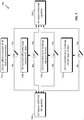
- FIG. 5 is a conceptual diagram illustrating a UE 502 dynamically reporting its data communication capability to a network (NW) 504 in accordance with an aspect of the disclosure.
- the UE 502 may be any of the UEs in FIG. 2 , and the network 504 may be the RAN 200.
- the UE 502 is capable of communicating data with the network 504 utilizing a number of communication protocols or standards such as UMTS Release 99, HSPA, HSDPA, HSUPA, HSPA+, LTE, etc.
- a UE has enhanced data communication capability when the UE can transfer data utilizing any one of the HSPA, HSDPA, HSUPA, HSPA+, LTE standards, and any other communication standards thereafter.
- the present disclosure is not limited to the disclosed wireless communication standards.
- the inventive concepts of the present disclosure may be applied to any UE that can support multiple communication standards with different data communication capabilities and maximum throughputs.
- the network 504 will configure its hardware and/or software resources to communicate with the UE 502 in an enhanced mode for better performance in terms of data throughput.
- the UE 502 may utilize an Enhanced Dedicated Channel (E-DCH) in the HSPA standards to achieve higher data throughput in the enhanced mode.
- E-DCH Enhanced Dedicated Channel
- the improvement in data throughput may degrade the UE's energy efficiency especially when the total amount of data transferred is reasonably small (e.g., less than 500 bits, 500 kbits, or any desired value).
- the UE 502 may initially transfer data with the network 504 utilizing a first communication protocol (e.g., UMTS Release 99) in a first communication channel (e.g., a dedicated transport channel (DCH) or a forward access channel (FCH)) (block 506).
- a first communication protocol e.g., UMTS Release 99
- a first communication channel e.g., a dedicated transport channel (DCH) or a forward access channel (FCH)
- the first communication protocol is not the UE's best data capability, but the UE may have better energy efficiency for the small amount of data transferred using the first communication protocol.
- the UE 502 analyzes the data characteristics (block 508) of the data received (e.g., downlink data) and/or data to be transmitted (e.g., uplink data) such that the UE 502 may determine which communication protocol (e.g., UMTS Release 99 or HSPA) should be utilized to achieve the desired balance of energy efficiency and data throughput.
- the data characteristics that are analyzed by the UE will be described in more detail below.
- the UE 502 may report its data communication capability using radio resource control (RRC) configuration parameters. Once the network 504 receives the UE capability report, the network 504 may consider the reported UE capability when configuring the radio bearers (RBs) or network grant.
- RRC radio resource control
- the UE's enhanced data capability e.g., HSPA
- data may be quickly transferred (UL and/or DL data) between the UE 502 and the network 504 assuming good radio conditions and sufficient grant from the network.
- utilizing the enhanced data capability can lead to configuration or deconfiguration of various hardware blocks or circuitries of the UE.
- the UE may enable/disable diversity receiver or receivers with more advanced interference cancellation and equalization functions.
- the hardware blocks or circuitries may be related to HSDPA specific circuitry for decoding the High-Speed Shared Control Channel (HS-SCCH) and Physical Downlink Shared Control Channel (PDSCH), EUL specific circuitry for encoding the transport blocks, and operations including Hybrid Automatic Repeat Request (HARQ) level buffer management in DL data as well as UL data and associated memory usage.
- the hardware blocks or circuitries may be related to the data movers and associated bus bandwidth.
- higher clock speed at system level may be used to support the enhanced data capability.
- HSDPA/EUL channels communication channels
- SW/FW software/firmware
- the UE 502 may not be energy efficient to configure and allocate enhanced (e.g., HSPA or EUL) channels to transmit the small amount of data.
- enhanced e.g., HSPA or EUL
- TTIs transmission time intervals
- the above-described configuration/deconfiguration overheads e.g., switching between HSPA and UMTS Release 99
- system level HW/SW/FW utilized along with higher clock rate
- the UE's enhanced data capability when the UE has sufficiently large amount of data traffic with the network.
- the amount of data can span across multiple TTIs in the UL and/or DL direction such as a large file transfer or video upload/download.
- Such strategic use of the enhanced data capacity at the UE can balance the gains in higher data throughput and the additional configuration/deconfiguration overheads described above.
- the energy efficiency of the UE may be more important than the data latency, considering the data activity as well as QoS requirements. In these types of UEs, data transmission utilizing enhanced capability may lead to undesirably high energy consumption.
- the UE 502 dynamically reports its capability to communicate in a second communication protocol with enhanced data capability based on the characteristics of the data transferred or to be transferred (block 510). Further, the UE configures its corresponding hardware or circuitries to transfer data in the second communication protocol (block 512). In addition, the UE may deconfigure or reconfigure the circuitries that are no longer needed to transfer data in the first communication protocol. Then, the UE may transfer data utilizing the second communication protocol in a second communication channel (e.g., HS data channels) (block 514).
- a second communication channel e.g., HS data channels
- the UE may report its capability to communicate in the second communication protocol if the energy efficiency will be equal to or greater than a desired energy efficiency threshold (e.g., a predetermined threshold); otherwise, the UE may report its capability to communicate in the first communication protocol if the energy efficiency will be less than the desired energy efficiency threshold.
- a desired energy efficiency threshold e.g., a predetermined threshold
- the UE when the UE is transferring data utilizing the second communication protocol, the UE continues to analyze data characteristics to determine when it is appropriate to switch back to the first communication protocol in consideration of data characteristics and/or its energy efficiency of transferring data in either one of the communication protocols. For example, when the UE expects only a small amount of UL and/or DL data traffic, it may revert back to utilizing the first communication protocol.
- FIG. 6 is a flowchart conceptually illustrating a procedure 600 operable at a UE to dynamically report data communication capability based on data characteristics in accordance with aspects of the disclosure.
- the data characteristics may include the activity, significance, and/or type of the data.
- the procedure 600 may be performed by the UE 502 that supports the UMTS standards.
- the two basic operational modes of a UE are idle mode and connected mode. After the UE is switched on, it will be in the idle mode and selects a public land mobile network (PLMN) to connect, e.g., RAN 200.
- PLMN public land mobile network
- the UE searches for a suitable cell of the chosen PLMN, chooses that cell to provide available services, and tunes to its control channels. This process is generally known as "camping on a cell.”
- the UE in block 602, the UE camps on a cell that supports the UMTS Release 99 protocol and an enhanced data access protocol (e.g., HSDPA, EUL, HSPA, HSPA+, LTE, etc.).
- an enhanced data access protocol e.g., HSDPA, EUL, HSPA, HSPA+, LTE, etc.
- the UE may initially report its capability as being UMTS Release 99 (block 604), or any other capability that is not its best capability.
- the UE may stay in a Forward Access Channel (FACH) mode for transferring data with the network (e.g., see block 506).
- FACH Forward Access Channel
- the UE While transferring data in the UMTS Release 99 mode, the UE analyzes data characteristics (e.g., DL data and/or UL data) and considers the configuration overheads for configuring the UE to communicate with its enhanced data capability (block 606). When the data characteristics meet certain conditions to be described in detail below, the UE may report its enhanced data capability (e.g., HSPA, HSPA+, or LTE) to the network (block 608); otherwise, it may continue to report its UMTS Release 99 capability (block 604). For example, in consideration of the configuration and/or deconfiguration overheads of the UE to transfer data in the enhanced communication protocol, the UE may report a suitable capability to achieve a desired balance of energy efficiency and data throughput by transmitting RRC configuration parameters to the network. More details of the RRC configuration parameters can be found in the 3GPP Technical Specification 25.331, which is incorporated herein by reference.
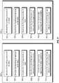
- FIG. 7 is a conceptual diagram illustrating a procedure 700 for analyzing data characteristics to dynamically report UE data communication capability in accordance with aspects of the disclosure.
- This procedure 700 may be performed by a UE 502 in block 508 of FIG. 5 and block 606 of FIG. 6 .
- the UE initially reports its capability as being UMTS Release 99.
- the UE may report its enhanced data capability (block 704); otherwise, the UE reports UMTS Release 99 capability (block 706).
- the UE if the UE has received a sufficiently large amount of DL data in a predetermined time period T (e.g., Y bits of data in T milliseconds (block 708), the UE reports its enhanced data capability; otherwise, the UE reports UMTS Release 99 capability.
- T e.g., Y bits of data in T milliseconds
- the UE reports its enhanced data capability; otherwise, the UE reports UMTS Release 99 capability.
- the UE if the UE is either transmitting or receiving data with a certain or predetermined priority (e.g., high priority data) (block 710), the UE reports its enhanced data capability; otherwise, the UE reports UMTS Release 99 capability.
- the UE if the UE is either transmitting or receiving certain or predetermined types of data (block 712), the UE may report its enhanced data capability; otherwise, the UE reports UMTS Release 99 capability.
- the type of data may have a strict QoS requirement or is time critical.
- the UE may dynamically report its enhanced data capability in consideration of configuration overheads so as to improve energy efficiency for the amount of data transferred.
- the UE dynamically reports its data communication capabilities such that it is operating with the desired energy efficiency whenever it is possible. That is, the UE can optimize or minimize its energy consumption for the amount of data transferred by dynamically reporting its data capabilities as exemplified in FIGs. 5-7 and the corresponding description above. In some applications, this kind of dynamic data capability reporting can help mobile-to-mobile devices reduce energy consumption when the devices are designed to transfer non-critical data.
- FIG. 8 is a conceptual diagram illustrating an example of a hardware implementation for an apparatus 800 employing a processing system 814.
- an element, or any portion of an element, or any combination of elements may be implemented with a processing system 814 that includes one or more processors 804.
- the apparatus 800 may be a user equipment (UE) as illustrated in any one or more of FIGs. 1 , 2 , 4 , and/or 5.
- the apparatus 800 may be a radio network controller (RNC) or Node B as illustrated in any one or more of FIGs. 1 , 2 , 4 and/or 5.
- RNC radio network controller
- processors 804 include microprocessors, microcontrollers, digital signal processors (DSPs), field programmable gate arrays (FPGAs), programmable logic devices (PLDs), state machines, gated logic, discrete hardware circuits, and other suitable hardware configured to perform the various functionality described throughout this disclosure. That is, the processor 804, as utilized in an apparatus 800, may be used to implement any one or more of the processes described throughout this specification and illustrated in FIGs. 5-7 and 10 .
- the processing system 814 may be implemented with a bus architecture, represented generally by the bus 802.
- the bus 802 may include any number of interconnecting buses and bridges depending on the specific application of the processing system 814 and the overall design constraints.
- the bus 802 links together various circuits including one or more processors (represented generally by the processor 804), a memory 805, and computer-readable storage media (represented generally by the computer-readable storage medium 806).
- the bus 802 may also link various other circuits such as timing sources, peripherals, voltage regulators, and power management circuits, which are well known in the art, and therefore, will not be described any further.
- a bus interface 808 provides an interface between the bus 802 and a transceiver 810.
- the transceiver 810 provides a means for communicating with various other apparatus over a transmission medium.
- a user interface 812 e.g., keypad, display, speaker, microphone, joystick, touchpad, touchscreen
- a user interface 812 e.g., keypad, display, speaker, microphone, joystick, touchpad, touchscreen
- the processor 804 may include a number of circuitries that may be configured to perform various functionalities to implement the processes described throughout this specification and illustrated in FIGs. 5-7 , for example.
- the computer-readable storage medium 806 may include a number of program routines that when executed by the processor 804 can configure the various circuitries of the processor 804 to perform the processes described throughout this specification and illustrated in FIGs. 5-7 .
- the processor 804 and routines stored on the computer-readable storage medium 806 will be described in more detail below.
- the processor 804 is responsible for managing the bus 802 and general processing, including the execution of software stored on the computer-readable storage medium 806.
- the software when executed by the processor 804, causes the processing system 814 to perform the various functions described infra for any particular apparatus.
- the computer-readable storage medium 806 may also be used for storing data that is manipulated by the processor 804 when executing software.
- One or more processors 804 in the processing system may execute software.
- Software shall be construed broadly to mean instructions, instruction sets, code, code segments, program code, programs, subprograms, software modules, applications, software applications, software packages, routines, subroutines, objects, executables, threads of execution, procedures, functions, etc., whether referred to as software, firmware, middleware, microcode, hardware description language, or otherwise.
- the software may reside on a computer-readable storage medium 806.
- the computer-readable storage medium 806 may be a non-transitory computer-readable storage medium.
- a non-transitory computer-readable storage medium includes, by way of example, a magnetic storage device (e.g., hard disk, floppy disk, magnetic strip), an optical disk (e.g., a compact disc (CD) or a digital versatile disc (DVD)), a smart card, a flash memory device (e.g., a card, a stick, or a key drive), a random access memory (RAM), a read only memory (ROM), a programmable ROM (PROM), an erasable PROM (EPROM), an electrically erasable PROM (EEPROM), a register, a removable disk, and any other suitable medium for storing software and/or instructions that may be accessed and read by a computer.
- a magnetic storage device e.g., hard disk, floppy disk, magnetic strip
- an optical disk e.g., a compact disc (CD) or a digital versatile disc (DVD)
- a smart card e.g., a flash memory device (e.g
- the computer-readable storage medium may also include, by way of example, a carrier wave, a transmission line, and any other suitable medium for transmitting software and/or instructions that may be accessed and read by a computer.
- the computer-readable storage medium 806 may reside in the processing system 814, external to the processing system 814, or distributed across multiple entities including the processing system 814.
- the computer-readable storage medium 806 may be embodied in a computer program product.
- a computer program product may include a computer-readable storage medium in packaging materials.
- FIG. 9 is a conceptual diagram illustrating a processor 900 and a computer-readable storage medium 920 for dynamically reporting UE data communication capability in accordance with aspects of the disclosure.
- the processor 902 may be the processor 804, and the computer-readable storage medium 920 may be the computer-readable storage medium 806.
- the processor 902 includes a first circuitry 902 for handling an amount of UL data, a second circuitry 904 for handling an amount of DL data, a third circuitry 906 for handling a priority of data, a fourth circuitry 908 for handling the types of data and QoS requirements, a fifth circuitry 910 for dynamically reporting UE data communication capability, and a sixth circuitry 912 for considering energy efficiency and configuration overheads. These circuitries will be described in more detail below.
- the computer-readable storage medium 920 includes a number of software routines that can be executed by the processor 900.
- the processor 900 may execute a first routine 922 to configure the first circuitry 902 to handle an amount of UL data that has been transmitted or will be transmitted.
- the processor 900 may execute a second routine 924 to configure the second circuitry 904 to handle an amount of DL data that has been received by the UE.
- the processor 900 may execute a third routine 926 to configure the third circuitry 906 to handle the priority of data transferred by the UE.
- the processor 900 may execute a fourth routine 928 to configure the fourth circuitry 908 to handle the types of data and QoS requirements of the data that has been transferred or will be transferred by the UE.
- the processor 900 may execute a fifth routine 930 to configure the fifth circuitry 910 to dynamically report UE data capability based on characteristics of the data such as the amount of UL/DL data, priority, types and/or QoS requirements of the data that are handled by one or more of the first through fourth circuitries (902, 904, 906, and 908).
- the processor 900 may execute a sixth routine 932 to configure the sixth circuitry 912 to consider energy efficiency and configuration overheads of the UE in order to determine which UE data communication capability (e.g., UMTS Release 99 or enhanced capability) to report to the network.
- UE data communication capability e.g., UMTS Release 99 or enhanced capability
- routines 922, 924, 926, and 928 may be executed to perform some or all of the processes illustrated in block 606 of FIG. 6 .
- routines 930 and 932 may be executed to perform some or all of the processes illustrated in blocks 606 and 608 of FIG. 6 .
- LTE Long Term Evolution
- LTE-A LTE-Advanced
- CDMA2000 Evolution-Data Optimized
- UMB Ultra Mobile Broadband
- IEEE 802.11 Wi-Fi
- IEEE 802.16 WiMAX
- IEEE 802.20 Ultra-Wideband
- Bluetooth Bluetooth
- the actual telecommunication standard, network architecture, and/or communication standard employed will depend on the specific application and the overall design constraints imposed on the system.
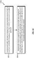
- FIG. 10 is a flowchart illustrating a method 1000 of dynamically reporting UE data communication capability in a wireless communication system in accordance with an aspect of the disclosure.
- the method 1000 may be performed by a UE 502.
- the UE is configured to communicate with a network 504 utilizing a plurality of communication protocols including a first communication protocol and a second communication protocol.
- the UE may initially communicate with the network utilizing the first communication protocol with a maximum achievable throughput less than that of the second communication protocol (block 1002).
- the UE may initially transfer data with the network utilizing a UMTS Release 99 protocol (e.g., see block 506 in FIG. 5 ).
- the UE dynamically reports a capability of the UE to transfer data utilizing the second communication protocol in consideration of an energy efficiency of transferring an amount of data utilizing the first communication protocol or the second communication protocol (block 1004).
- the UE analyzes data characteristics (e.g., block 508 in FIG. 5 ) and configuration overheads (e.g., block 606 in FIG. 6 ), and dynamically reports a capability of the UE to transfer data in an enhanced protocol (e.g., message 510 in FIG. 5 ) in consideration of an energy efficiency of transferring an amount of data utilizing UMTS Release 99 or enhanced capability.
Description
- Aspects of the present disclosure relate generally to wireless communication systems, and more particularly, to user equipment capability reporting in a wireless communication system.
- Wireless communication networks are widely deployed to provide various communication services such as telephony, video, data, messaging, broadcasts, video telephony, and so on. Such networks, which are usually multiple access networks, support communications for multiple users by sharing the available network resources. One example of such a network is the UMTS Terrestrial Radio Access Network (UTRAN). The UTRAN is the radio access network (RAN) defined as a part of the Universal Mobile Telecommunications System (UMTS), a third generation (3G) mobile phone technology supported by the 3rd Generation Partnership Project (3GPP). UMTS, which is the successor to Global System for Mobile Communications (GSM) technologies, currently supports various air interface standards, such as Wideband Code Division Multiple Access (W-CDMA), Time Division-Code Division Multiple Access (TD-CDMA), and Time Division-Synchronous Code Division Multiple Access (TD-SCDMA). UMTS also supports enhanced 3G data communications protocols, such as High Speed Downlink Package Access (HSDPA), High Speed Uplink Package Access (HSUPA), also known as Enhanced Uplink (EUL), and High Speed Packet Access (HSPA), which provide higher data transfer speeds and capacity to associated UMTS networks.
- An example of an emerging telecommunication standard is Long Term Evolution (LTE) that is a set of enhancements to the UMTS mobile standard promulgated by 3GPP. It is designed to better support mobile broadband Internet access by improving spectral efficiency, lower costs, improve services, make use of new spectrum, and better integrate with other open standards using orthogonal frequency-division multiple access (OFDMA) on the downlink (DL), single-carrier FDMA (SC-FDMA) on the uplink (UL), and multiple-input multiple-output (MIMO) antenna technology.
- A user equipment (UE) with enhanced data communication capability such as HSPA and LTE typically reports its enhanced or best capability to the network whenever enhanced capability is available or supported. However, the UE generally consumes more power when it exchanges data with the network using its enhanced capability, and switching the UE between different communication protocols involves configuration overheads that can lower the UE's energy efficiency.
- Another example of a prior art system is disclosed in
US 2009/068969 A1 . - The following presents a simplified summary of one or more aspects of the present disclosure, in order to provide a basic understanding of such aspects. This summary is not an extensive overview of all contemplated features of the disclosure, and is intended neither to identify key or critical elements of all aspects of the disclosure nor to delineate the scope of any or all aspects of the disclosure. Its sole purpose is to present some concepts of one or more aspects of the disclosure in a simplified form as a prelude to the more detailed description that is presented later.
- Aspects of the disclosure provide apparatuses and methods for dynamic user equipment capability reporting in a first communication protocol or second communication protocol based on data activity. In some aspects of the disclosure, the first communication protocol may be a
UMTS Release 99 protocol, and the second communication protocol may be an HSDPA, HSUPA, HSPA, HSPA+, EUL, or LTE protocol. - In one aspect, the disclosure provides a method of wireless communication operable at a user equipment (UE). The UE communicates with a network utilizing a first communication protocol with a maximum achievable throughput less than that of a second communication protocol. Further, the UE dynamically reports a capability to transfer data utilizing the second communication protocol in consideration of an energy efficiency of transferring an amount of data utilizing the first communication protocol or the second communication protocol.
- Another aspect of the disclosure provides an apparatus for wireless communication. The apparatus includes means for communicating with a network utilizing a first communication protocol with a maximum achievable throughput less than that of a second communication protocol. The apparatus further includes means for dynamically reporting a capability of the apparatus to transfer data utilizing the second communication protocol in consideration of an energy efficiency of transferring an amount of data utilizing the first communication protocol or the second communication protocol.
- Another aspect of the disclosure provides a computer program product including a computer-readable storage medium. The computer-readable storage medium includes code for causing a user equipment (UE) to perform various functions. For example, the code causes the UE to communicate with a network utilizing a first communication protocol with a maximum achievable throughput less than that of a second communication protocol, and the code causes the UE to dynamically report a capability of the UE to transfer data utilizing the second communication protocol in consideration of an energy efficiency of transferring an amount of data utilizing the first communication protocol or the second communication protocol.
- Another aspect of the disclosure provides an apparatus for wireless communication. The apparatus includes at least one processor, a communication interface coupled to the at least one processor, and a memory coupled to the at least one processor. The at least one processor includes first circuitry configured to communicate with a network utilizing a first communication protocol with a maximum achievable throughput less than that of a second communication protocol. The at least one processor further include second circuitry configured to dynamically report a capability of the apparatus to transfer data utilizing the second communication protocol in consideration of an energy efficiency of transferring an amount of data utilizing the first communication protocol or the second communication protocol.
- These and other aspects of the invention will become more fully understood upon a review of the detailed description, which follows. Other aspects, features, and embodiments of the present invention will become apparent to those of ordinary skill in the art, upon reviewing the following description of specific, exemplary embodiments of the present invention in conjunction with the accompanying figures. While features of the present invention may be discussed relative to certain embodiments and figures below, all embodiments of the present invention can include one or more of the advantageous features discussed herein. In other words, while one or more embodiments may be discussed as having certain advantageous features, one or more of such features may also be used in accordance with the various embodiments of the invention discussed herein. In similar fashion, while exemplary embodiments may be discussed below as device, system, or method embodiments it should be understood that such exemplary embodiments can be implemented in various devices, systems, and methods.
-
-
FIG. 1 is a block diagram conceptually illustrating an example of a telecommunications system in accordance with aspects of the disclosure. -
FIG. 2 is a conceptual diagram illustrating an example of a radio access network in accordance with aspects of the disclosure. -
FIG. 3 is a conceptual diagram illustrating an example of a radio protocol architecture for the user and control plane. -
FIG. 4 is a conceptual diagram illustrating an example of a Node B in communication with a user equipment (UE) in a telecommunications system in accordance with aspects of the disclosure. -
FIG. 5 is a conceptual message flow diagram illustrating a UE dynamically reporting its data communication capability to a network based on characteristics of data in accordance with aspects of the disclosure. -
FIG. 6 is a flowchart conceptually illustrating a procedure for dynamically reporting data communication capability based on characteristics of data in accordance with aspects of the disclosure. -
FIG. 7 is a flowchart conceptual illustrating a procedure for analyzing UE data characteristics to dynamically report UE data communication capability in accordance with aspects of the disclosure. -
FIG. 8 is a conceptual diagram illustrating an example of a hardware implementation for an apparatus employing a processing system in accordance with an aspect of the disclosure. -
FIG. 9 is a conceptual diagram illustrating a processor and a computer-readable storage medium for dynamically reporting UE data communication capability in accordance with aspects of the disclosure. -
FIG. 10 is a flowchart illustrating a method of dynamically reporting UE data communication capability in a wireless communication system in accordance with an aspect of the disclosure. - The detailed description set forth below in connection with the appended drawings is intended as a description of various configurations and is not intended to represent the only configurations in which the concepts described herein may be practiced. The detailed description includes specific details for the purpose of providing a thorough understanding of various concepts. However, it will be apparent to those skilled in the art that these concepts may be practiced without these specific details. In some instances, well known structures and components are shown in block diagram form in order to avoid obscuring such concepts.
- Aspects of the disclosure provide an apparatus and methods for dynamic user equipment (UE) access (data communication) capability reporting based on various factors such as data activity, QoS requirement, priority of data, for example. The UE dynamically reports its access capability information to the network so as to transfer data with a desirable power efficiency in consideration of reconfiguration overhead when switching between communication protocols. For example, a UE capable of communicating data in UMTS
Release 99 and enhanced data capability (e.g., HSPA or LTE) may initially report its capability being UMTS Release 99 (not UE's best capability) to reduce its power consumption. Then when a certain condition is met with respect to the amount of data activity or the significance of the data, the UE may dynamically report its capability being its enhanced capability. This novel capability reporting approach is different from a typical approach in which a UE reports its best capability whenever it is available. - The various concepts presented throughout this disclosure may be implemented across a broad variety of telecommunication systems, network architectures, and communication standards. Referring now to
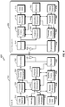
FIG. 1 , as an illustrative example without limitation, various aspects of the present disclosure are illustrated with reference to a Universal Mobile Telecommunications System (UMTS)system 100. A UMTS network includes three interacting domains: acore network 104, a radio access network (RAN) (e.g., the UMTS Terrestrial Radio Access Network (UTRAN) 102), and a user equipment (UE) 110. In an aspect, the UE 110 may be implemented using theapparatus 100. Among several options available for a UTRAN 102, in this example, the illustrated UTRAN 102 may employ a W-CDMA air interface for enabling various wireless services including telephony, video, data, messaging, broadcasts, and/or other services. The UTRAN 102 may include a plurality of Radio Network Subsystems (RNSs) such as anRNS 107, each controlled by a respective Radio Network Controller (RNC) such as anRNC 106. Here, theUTRAN 102 may include any number ofRNCs 106 andRNSs 107 in addition to the illustratedRNCs 106 andRNSs 107. TheRNC 106 is an apparatus responsible for, among other things, assigning, reconfiguring, and releasing radio resources within theRNS 107. TheRNC 106 may be interconnected to other RNCs (not shown) in theUTRAN 102 through various types of interfaces such as a direct physical connection, a virtual network, or the like using any suitable transport network. - The geographic region covered by the
RNS 107 may be divided into a number of cells, with a radio transceiver apparatus serving each cell. A radio transceiver apparatus is commonly referred to as a Node B in UMTS applications, but may also be referred to by those skilled in the art as a base station (BS), a base transceiver station (BTS), a radio base station, a radio transceiver, a transceiver function, a basic service set (BSS), an extended service set (ESS), an access point (AP), or some other suitable terminology. For clarity, threeNode Bs 108 are shown in eachRNS 107; however, theRNSs 107 may include any number of wireless Node Bs. TheNode Bs 108 provide wireless access points to acore network 104 for any number of mobile apparatuses. Examples of a mobile apparatus include a cellular phone, a smart phone, a session initiation protocol (SIP) phone, a laptop, a notebook, a netbook, a smartbook, a personal digital assistant (PDA), a satellite radio, a global positioning system (GPS) device, a multimedia device, a video device, a digital audio player (e.g., MP3 player), a camera, a game console, or any other similar functioning device. The mobile apparatus is commonly referred to as user equipment (UE) in UMTS applications, but may also be referred to by those skilled in the art as a mobile station (MS), a subscriber station, a mobile unit, a subscriber unit, a wireless unit, a remote unit, a mobile device, a wireless device, a wireless communications device, a remote device, a mobile subscriber station, an access terminal (AT), a mobile terminal, a wireless terminal, a remote terminal, a handset, a terminal, a user agent, a mobile client, a client, or some other suitable terminology. In a UMTS system, theUE 110 may further include a universal subscriber identity module (USIM) 111, which contains a user's subscription information to a network. For illustrative purposes, oneUE 110 is shown in communication with a number of theNode Bs 108. The downlink (DL), also called the forward link, refers to the communication link from aNode B 108 to aUE 110 and the uplink (UL), also called the reverse link, refers to the communication link from aUE 110 to aNode B 108. - The
core network 104 can interface with one or more access networks, such as theUTRAN 102. As shown, thecore network 104 is a UMTS core network. However, as those skilled in the art will recognize, the various concepts presented throughout this disclosure may be implemented in a RAN, or other suitable access network, to provide UEs with access to types of core networks other than UMTS networks. - The illustrated
UMTS core network 104 includes a circuit-switched (CS) domain and a packet-switched (PS) domain. Some of the circuit-switched elements are a Mobile services Switching Centre (MSC), a Visitor Location Register (VLR), and a Gateway MSC (GMSC). Packet-switched elements include a Serving GPRS Support Node (SGSN) and a Gateway GPRS Support Node (GGSN). Some network elements, like EIR, HLR, VLR, and AuC may be shared by both of the circuit-switched and packet-switched domains. - In the illustrated example, the
core network 104 supports circuit-switched services with aMSC 112 and aGMSC 114. In some applications, theGMSC 114 may be referred to as a media gateway (MGW). One or more RNCs, such as theRNC 106, may be connected to theMSC 112. TheMSC 112 is an apparatus that controls call setup, call routing, and UE mobility functions. TheMSC 112 also includes a visitor location register (VLR) that contains subscriber-related information for the duration that a UE is in the coverage area of theMSC 112. TheGMSC 114 provides a gateway through theMSC 112 for the UE to access a circuit-switchednetwork 116. TheGMSC 114 includes a home location register (HLR) 115 containing subscriber data, such as the data reflecting the details of the services to which a particular user has subscribed. The HLR is also associated with an authentication center (AuC) that contains subscriber-specific authentication data. When a call is received for a particular UE, theGMSC 114 queries theHLR 115 to determine the UE's location and forwards the call to the particular MSC serving that location. - The illustrated
core network 104 also supports packet-switched data services with a serving GPRS support node (SGSN) 118 and a gateway GPRS support node (GGSN) 120. General Packet Radio Service (GPRS) is designed to provide packet-data services at speeds higher than those available with standard circuit-switched data services. TheGGSN 120 provides a connection for theUTRAN 102 to a packet-basednetwork 122. The packet-basednetwork 122 may be the Internet, a private data network, or some other suitable packet-based network. The primary function of theGGSN 120 is to provide theUEs 110 with packet-based network connectivity. Data packets may be transferred between theGGSN 120 and theUEs 110 through theSGSN 118, which performs primarily the same functions in the packet-based domain as theMSC 112 performs in the circuit-switched domain. - The
UTRAN 102 is one example of a RAN that may be utilized in accordance with aspects of the present disclosure. Referring toFIG. 2 , by way of example and without limitation, a simplified schematic illustration of aRAN 200 in a UTRAN architecture is illustrated. The system includes multiple cellular regions (cells), includingcells cells cell 204a may utilize a first scrambling code, and cell 204b, while in the same geographic region and served by thesame Node B 244, may be distinguished by utilizing a second scrambling code. In some aspects of the disclosure, theRAN 200 may be an Evolved UMTS Terrestrial Radio Access Network (E-UTRAN) that supports LTE access. - In a cell that is divided into sectors, the multiple sectors within a cell can be formed by groups of antennas with each antenna responsible for communication with UEs in a portion of the cell. For example, in
cell 202,antenna groups antenna groups cell 206,antenna groups - The
cells cell UEs Node B 242,UEs Node B 244, andUEs Node B 246. Here, eachNode B FIG. 2 ) for all theUEs respective cells - During a call with a source cell, or at any other time, the
UE 236 may monitor various parameters of the source cell as well as various parameters of neighboring cells. Further, depending on the quality of these parameters, theUE 236 may maintain communication with one or more of the neighboring cells. During this time, theUE 236 may maintain an Active Set, that is, a list of cells to which theUE 236 is simultaneously connected (i.e., the UTRAN cells that are currently assigning a downlink dedicated physical channel DPCH or fractional downlink dedicated physical channel F-DPCH to theUE 236 may constitute the Active Set). - The UTRAN air interface may be a spread spectrum Direct-Sequence Code Division Multiple Access (DS-CDMA) system, such as one utilizing the W-CDMA standards. The spread spectrum DS-CDMA spreads user data through multiplication by a sequence of pseudorandom bits called chips. The W-CDMA air interface for the
UTRAN 102 is based on such DS-CDMA technology and additionally calls for a frequency division duplexing (FDD). FDD uses a different carrier frequency for the uplink (UL) and downlink (DL) between a Node B 408 and a UE 210. Another air interface for UMTS that utilizes DS-CDMA, and uses time division duplexing (TDD), is the TD-SCDMA air interface. Those skilled in the art will recognize that although various examples described herein may refer to a W-CDMA air interface, the underlying principles are equally applicable to a TD-SCDMA air interface or any other suitable air interface. - A high speed packet access (HSPA) air interface includes a series of enhancements to the 3G/W-CDMA air interface between the UE 210 and the
UTRAN 202, facilitating greater throughput and reduced latency for users. Among other modifications over prior standards, HSPA utilizes hybrid automatic repeat request (HARQ), shared channel transmission, and adaptive modulation and coding. The standards that define HSPA include HSDPA (high speed downlink packet access) and HSUPA (high speed uplink packet access, also referred to as enhanced uplink or EUL). - In a wireless telecommunication system, the communication protocol architecture may take on various forms depending on the particular application. For example, in a 3GPP UMTS system, the signaling protocol stack is divided into a Non-Access Stratum (NAS) and an Access Stratum (AS). The NAS provides the upper layers, for signaling between the
UE 110 and the core network 104 (referring toFIG. 1 ), and may include circuit switched and packet switched protocols. The AS provides the lower layers, for signaling between theUTRAN 102 and theUE 110, and may include a user plane and a control plane. Here, the user plane or data plane carries user traffic, while the control plane carries control information (i.e., signaling). - Turning to
FIG. 3 , the AS is shown with three layers: Layer 1, Layer 2, and Layer 3. Layer 1 is the lowest layer and implements various physical layer signal processing functions. Layer 1 will be referred to herein as thephysical layer 306. The data link layer, called Layer 2 308, is above thephysical layer 306 and is responsible for the link between theUE 110 andNode B 108 over thephysical layer 306. - At Layer 3, the
RRC layer 316 handles the control plane signaling between theUE 110 and theNode B 108.RRC layer 316 includes a number of functional entities for reporting UE capabilities, routing higher layer messages, handling broadcasting and paging functions, establishing and configuring radio bearers, etc. - In the illustrated air interface, the
L2 layer 308 is split into sublayers. In the control plane, theL2 layer 308 includes two sublayers: a medium access control (MAC)sublayer 310 and a radio link control (RLC)sublayer 312. In the user plane, theL2 layer 308 additionally includes a packet data convergence protocol (PDCP)sublayer 314. Although not shown, the UE may have several upper layers above theL2 layer 308 including a network layer (e.g., IP layer) that is terminated at a PDN gateway on the network side and an application layer that is terminated at the other end of the connection (e.g., far end UE, server, etc.). - The
PDCP sublayer 314 provides multiplexing between different radio bearers and logical channels. ThePDCP sublayer 314 also provides header compression for upper layer data packets to reduce radio transmission overhead, security by ciphering the data packets, and handover support for UEs between Node Bs. - The
RLC sublayer 312 generally supports an acknowledged mode (AM) (where an acknowledgment and retransmission process may be used for error correction), an unacknowledged mode (UM), and a transparent mode for data transfers, and provides segmentation and reassembly of upper layer data packets and reordering of data packets to compensate for out-of-order reception due to a hybrid automatic repeat request (HARQ) at the MAC layer. In the acknowledged mode, RLC peer entities such as an RNC and a UE may exchange various RLC protocol data units (PDUs) including RLC Data PDUs, RLC Status PDUs, and RLC Reset PDUs, among others. In the present disclosure, the term "packet" may refer to any RLC PDU exchanged between RLC peer entities. - The
MAC sublayer 310 provides multiplexing between logical and transport channels. TheMAC sublayer 310 is also responsible for allocating the various radio resources (e.g., resource blocks) in one cell among the UEs. TheMAC sublayer 310 is also responsible for HARQ operations. -
FIG. 4 is a block diagram of anexemplary Node B 410 in communication with anexemplary UE 450, where theNode B 410 may be theNode B 108 inFIG. 1 , and theUE 450 may be theUE 110 inFIG. 1 . In the downlink communication, a transmitprocessor 420 may receive data from adata source 412 and control signals from a controller/processor 440. The transmitprocessor 420 provides various signal processing functions for the data and control signals, as well as reference signals (e.g., pilot signals). For example, the transmitprocessor 420 may provide cyclic redundancy check (CRC) codes for error detection, coding and interleaving to facilitate forward error correction (FEC), mapping to signal constellations based on various modulation schemes (e.g., binary phase-shift keying (BPSK), quadrature phase-shift keying (QPSK), M-phase-shift keying (M-PSK), M-quadrature amplitude modulation (M-QAM), and the like), spreading with orthogonal variable spreading factors (OVSF), and multiplying with scrambling codes to produce a series of symbols. Channel estimates from achannel processor 444 may be used by a controller/processor 440 to determine the coding, modulation, spreading, and/or scrambling schemes for the transmitprocessor 420. These channel estimates may be derived from a reference signal transmitted by theUE 450 or from feedback from theUE 450. The symbols generated by the transmitprocessor 420 are provided to a transmitframe processor 430 to create a frame structure. The transmitframe processor 430 creates this frame structure by multiplexing the symbols with information from the controller/processor 440, resulting in a series of frames. The frames are then provided to atransmitter 432, which provides various signal conditioning functions including amplifying, filtering, and modulating the frames onto a carrier for downlink transmission over the wireless medium throughantenna 434. Theantenna 434 may include one or more antennas, for example, including beam steering bidirectional adaptive antenna arrays or other similar beam technologies. - At the
UE 450, areceiver 454 receives the downlink transmission through anantenna 452 and processes the transmission to recover the information modulated onto the carrier. The information recovered by thereceiver 454 is provided to a receiveframe processor 460, which parses each frame, and provides information from the frames to achannel processor 494 and the data, control, and reference signals to a receiveprocessor 470. The receiveprocessor 470 then performs the inverse of the processing performed by the transmitprocessor 420 in theNode B 410. More specifically, the receiveprocessor 470 descrambles and despreads the symbols, and then determines the most likely signal constellation points transmitted by theNode B 410 based on the modulation scheme. These soft decisions may be based on channel estimates computed by thechannel processor 494. The soft decisions are then decoded and deinterleaved to recover the data, control, and reference signals. The CRC codes are then checked to determine whether the frames were successfully decoded. The data carried by the successfully decoded frames will then be provided to adata sink 472, which represents applications running in theUE 450 and/or various user interfaces (e.g., display). Control signals carried by successfully decoded frames will be provided to a controller/processor 490. When frames are unsuccessfully decoded by thereceiver processor 470, the controller/processor 490 may also use an acknowledgement (ACK) and/or negative acknowledgement (NACK) protocol to support retransmission requests for those frames. - In the uplink, data from a
data source 478 and control signals from the controller/processor 490 are provided to a transmitprocessor 480. Thedata source 478 may represent applications running in theUE 450 and various user interfaces (e.g., keyboard). Similar to the functionality described in connection with the downlink transmission by theNode B 410, the transmitprocessor 480 provides various signal processing functions including CRC codes, coding and interleaving to facilitate FEC, mapping to signal constellations, spreading with OVSFs, and scrambling to produce a series of symbols. Channel estimates, derived by thechannel processor 494 from a reference signal transmitted by theNode B 410 or from feedback contained in the midamble transmitted by theNode B 410, may be used to select the appropriate coding, modulation, spreading, and/or scrambling schemes. The symbols produced by the transmitprocessor 480 will be provided to a transmitframe processor 482 to create a frame structure. The transmitframe processor 482 creates this frame structure by multiplexing the symbols with information from the controller/processor 490, resulting in a series of frames. The frames are then provided to atransmitter 456, which provides various signal conditioning functions including amplification, filtering, and modulating the frames onto a carrier for uplink transmission over the wireless medium through theantenna 452. - The uplink transmission is processed at the
Node B 410 in a manner similar to that described in connection with the receiver function at theUE 450. Areceiver 435 receives the uplink transmission through theantenna 434 and processes the transmission to recover the information modulated onto the carrier. The information recovered by thereceiver 435 is provided to a receiveframe processor 436, which parses each frame, and provides information from the frames to thechannel processor 444 and the data, control, and reference signals to a receiveprocessor 438. The receiveprocessor 438 performs the inverse of the processing performed by the transmitprocessor 480 in theUE 450. The data and control signals carried by the successfully decoded frames may then be provided to adata sink 439 and the controller/processor, respectively. If some of the frames were unsuccessfully decoded by the receive processor, the controller/processor 440 may also use an acknowledgement (ACK) and/or negative acknowledgement (NACK) protocol to support retransmission requests for those frames. - The controller/
processors 440 and 490 may be used to direct the operation at theNode B 410 and theUE 450, respectively. For example, the controller/processors 440 and 490 may provide various functions including timing, peripheral interfaces, voltage regulation, power management, and other control functions. The computer readable storage media ofmemories Node B 410 and theUE 450, respectively. A scheduler/processor 446 at theNode B 410 may be used to allocate resources to the UEs and schedule downlink and/or uplink transmissions for the UEs. In various aspects, theUE 450 is capable of communicating with theNode B 410 in enhanced UMTS protocols such as HSDPA, HSUPA (EUL), HSPA, or HSPA+. -
FIG. 5 is a conceptual diagram illustrating aUE 502 dynamically reporting its data communication capability to a network (NW) 504 in accordance with an aspect of the disclosure. TheUE 502 may be any of the UEs inFIG. 2 , and thenetwork 504 may be theRAN 200. TheUE 502 is capable of communicating data with thenetwork 504 utilizing a number of communication protocols or standards such asUMTS Release 99, HSPA, HSDPA, HSUPA, HSPA+, LTE, etc. In various aspects of this disclosure, a UE has enhanced data communication capability when the UE can transfer data utilizing any one of the HSPA, HSDPA, HSUPA, HSPA+, LTE standards, and any other communication standards thereafter. However, the present disclosure is not limited to the disclosed wireless communication standards. The inventive concepts of the present disclosure may be applied to any UE that can support multiple communication standards with different data communication capabilities and maximum throughputs. - If the
UE 502 reports its enhanced data capability to thenetwork 504, the network will configure its hardware and/or software resources to communicate with theUE 502 in an enhanced mode for better performance in terms of data throughput. For example, theUE 502 may utilize an Enhanced Dedicated Channel (E-DCH) in the HSPA standards to achieve higher data throughput in the enhanced mode. Although theUE 502 andnetwork 504 can exchange data more quickly using the enhanced capability, the improvement in data throughput may degrade the UE's energy efficiency especially when the total amount of data transferred is reasonably small (e.g., less than 500 bits, 500 kbits, or any desired value). In one example, theUE 502 may initially transfer data with thenetwork 504 utilizing a first communication protocol (e.g., UMTS Release 99) in a first communication channel (e.g., a dedicated transport channel (DCH) or a forward access channel (FCH)) (block 506). In this case, the first communication protocol is not the UE's best data capability, but the UE may have better energy efficiency for the small amount of data transferred using the first communication protocol. - The
UE 502 analyzes the data characteristics (block 508) of the data received (e.g., downlink data) and/or data to be transmitted (e.g., uplink data) such that theUE 502 may determine which communication protocol (e.g.,UMTS Release 99 or HSPA) should be utilized to achieve the desired balance of energy efficiency and data throughput. The data characteristics that are analyzed by the UE will be described in more detail below. In an aspect of the disclosure, theUE 502 may report its data communication capability using radio resource control (RRC) configuration parameters. Once thenetwork 504 receives the UE capability report, thenetwork 504 may consider the reported UE capability when configuring the radio bearers (RBs) or network grant. - When the UE's enhanced data capability (e.g., HSPA) is utilized, data may be quickly transferred (UL and/or DL data) between the
UE 502 and thenetwork 504 assuming good radio conditions and sufficient grant from the network. However, utilizing the enhanced data capability can lead to configuration or deconfiguration of various hardware blocks or circuitries of the UE. For example, the UE may enable/disable diversity receiver or receivers with more advanced interference cancellation and equalization functions. In one example, the hardware blocks or circuitries may be related to HSDPA specific circuitry for decoding the High-Speed Shared Control Channel (HS-SCCH) and Physical Downlink Shared Control Channel (PDSCH), EUL specific circuitry for encoding the transport blocks, and operations including Hybrid Automatic Repeat Request (HARQ) level buffer management in DL data as well as UL data and associated memory usage. In some examples, the hardware blocks or circuitries may be related to the data movers and associated bus bandwidth. In addition, higher clock speed at system level may be used to support the enhanced data capability. - In a further example, when the
UE 502 is configured to utilize the HSDPA/EUL protocol, configuration of HSDPA/EUL channels (communication channels) will take considerable amount of time in terms of the physical layer CPHY-primitives, MAC layer CMAC-primitives and RLC layer CRLC-primitives handling procedures as well as software/firmware (SW/FW) interactions to ensure the channel configuration is in the right order. Also, deconfiguration of the HSDPA/EUL channels will take some time in terms of tearing down the channels and transitioning back to the FACH/Idle state in theUMTS Release 99 mode. Therefore, if theUE 502 has a small amount of data (e.g., about 500 bytes or less) to transmit in the UL direction, it may not be energy efficient to configure and allocate enhanced (e.g., HSPA or EUL) channels to transmit the small amount of data. Considering the number of data blocks and number of transmission time intervals (TTIs) that will be used to send the small amount of data, the above-described configuration/deconfiguration overheads (e.g., switching between HSPA and UMTS Release 99) as well as system level HW/SW/FW utilized along with higher clock rate, it may be undesirable to use the enhanced data capability in terms of energy efficiency in consideration of the amount of data transferred. - In some cases, it will be more beneficial to utilize the UE's enhanced data capability when the UE has sufficiently large amount of data traffic with the network. For example, the amount of data can span across multiple TTIs in the UL and/or DL direction such as a large file transfer or video upload/download. Such strategic use of the enhanced data capacity at the UE can balance the gains in higher data throughput and the additional configuration/deconfiguration overheads described above. For certain types of UEs (e.g., machine-to-machine type), the energy efficiency of the UE may be more important than the data latency, considering the data activity as well as QoS requirements. In these types of UEs, data transmission utilizing enhanced capability may lead to undesirably high energy consumption.
- Referring back to
FIG. 5 , theUE 502 dynamically reports its capability to communicate in a second communication protocol with enhanced data capability based on the characteristics of the data transferred or to be transferred (block 510). Further, the UE configures its corresponding hardware or circuitries to transfer data in the second communication protocol (block 512). In addition, the UE may deconfigure or reconfigure the circuitries that are no longer needed to transfer data in the first communication protocol. Then, the UE may transfer data utilizing the second communication protocol in a second communication channel (e.g., HS data channels) (block 514). In one aspect of the disclosure, the UE may report its capability to communicate in the second communication protocol if the energy efficiency will be equal to or greater than a desired energy efficiency threshold (e.g., a predetermined threshold); otherwise, the UE may report its capability to communicate in the first communication protocol if the energy efficiency will be less than the desired energy efficiency threshold. - In another aspect of the disclosure, when the UE is transferring data utilizing the second communication protocol, the UE continues to analyze data characteristics to determine when it is appropriate to switch back to the first communication protocol in consideration of data characteristics and/or its energy efficiency of transferring data in either one of the communication protocols. For example, when the UE expects only a small amount of UL and/or DL data traffic, it may revert back to utilizing the first communication protocol.
-
FIG. 6 is a flowchart conceptually illustrating aprocedure 600 operable at a UE to dynamically report data communication capability based on data characteristics in accordance with aspects of the disclosure. The data characteristics may include the activity, significance, and/or type of the data. In an aspect of the disclosure, theprocedure 600 may be performed by theUE 502 that supports the UMTS standards. In theUMTS Release 99 standard, the two basic operational modes of a UE are idle mode and connected mode. After the UE is switched on, it will be in the idle mode and selects a public land mobile network (PLMN) to connect, e.g.,RAN 200. The UE searches for a suitable cell of the chosen PLMN, chooses that cell to provide available services, and tunes to its control channels. This process is generally known as "camping on a cell." - Referring to
FIG. 6 , inblock 602, the UE camps on a cell that supports theUMTS Release 99 protocol and an enhanced data access protocol (e.g., HSDPA, EUL, HSPA, HSPA+, LTE, etc.). After camped on the cell, the UE may initially report its capability as being UMTS Release 99 (block 604), or any other capability that is not its best capability. Here, the UE may stay in a Forward Access Channel (FACH) mode for transferring data with the network (e.g., see block 506). While transferring data in theUMTS Release 99 mode, the UE analyzes data characteristics (e.g., DL data and/or UL data) and considers the configuration overheads for configuring the UE to communicate with its enhanced data capability (block 606). When the data characteristics meet certain conditions to be described in detail below, the UE may report its enhanced data capability (e.g., HSPA, HSPA+, or LTE) to the network (block 608); otherwise, it may continue to report itsUMTS Release 99 capability (block 604). For example, in consideration of the configuration and/or deconfiguration overheads of the UE to transfer data in the enhanced communication protocol, the UE may report a suitable capability to achieve a desired balance of energy efficiency and data throughput by transmitting RRC configuration parameters to the network. More details of the RRC configuration parameters can be found in the 3GPP Technical Specification 25.331, which is incorporated herein by reference. -
FIG. 7 is a conceptual diagram illustrating aprocedure 700 for analyzing data characteristics to dynamically report UE data communication capability in accordance with aspects of the disclosure. Thisprocedure 700 may be performed by aUE 502 inblock 508 ofFIG. 5 and block 606 ofFIG. 6 . By way of example and not limitation, it is assumed that the UE initially reports its capability as beingUMTS Release 99. In a first scenario, if the UE has a sufficiently large amount of UL data for transmission (e.g., above a threshold or predetermined amount of data bits (e.g., 500 bits)) (block 702), the UE may report its enhanced data capability (block 704); otherwise, the UE reportsUMTS Release 99 capability (block 706). In another scenario, if the UE has received a sufficiently large amount of DL data in a predetermined time period T (e.g., Y bits of data in T milliseconds (block 708), the UE reports its enhanced data capability; otherwise, the UE reportsUMTS Release 99 capability. In another scenario, if the UE is either transmitting or receiving data with a certain or predetermined priority (e.g., high priority data) (block 710), the UE reports its enhanced data capability; otherwise, the UE reportsUMTS Release 99 capability. In another scenario, if the UE is either transmitting or receiving certain or predetermined types of data (block 712), the UE may report its enhanced data capability; otherwise, the UE reportsUMTS Release 99 capability. In one example, the type of data may have a strict QoS requirement or is time critical. In another aspect of the disclosure, when one or more of the conditions insteps - In various aspects of the disclosure, the UE dynamically reports its data communication capabilities such that it is operating with the desired energy efficiency whenever it is possible. That is, the UE can optimize or minimize its energy consumption for the amount of data transferred by dynamically reporting its data capabilities as exemplified in
FIGs. 5-7 and the corresponding description above. In some applications, this kind of dynamic data capability reporting can help mobile-to-mobile devices reduce energy consumption when the devices are designed to transfer non-critical data. -
FIG. 8 is a conceptual diagram illustrating an example of a hardware implementation for anapparatus 800 employing aprocessing system 814. In accordance with various aspects of the disclosure, an element, or any portion of an element, or any combination of elements may be implemented with aprocessing system 814 that includes one ormore processors 804. For example, theapparatus 800 may be a user equipment (UE) as illustrated in any one or more ofFIGs. 1 ,2 ,4 , and/or 5. In another example, theapparatus 800 may be a radio network controller (RNC) or Node B as illustrated in any one or more ofFIGs. 1 ,2 ,4 and/or 5. Examples ofprocessors 804 include microprocessors, microcontrollers, digital signal processors (DSPs), field programmable gate arrays (FPGAs), programmable logic devices (PLDs), state machines, gated logic, discrete hardware circuits, and other suitable hardware configured to perform the various functionality described throughout this disclosure. That is, theprocessor 804, as utilized in anapparatus 800, may be used to implement any one or more of the processes described throughout this specification and illustrated inFIGs. 5-7 and10 . - In this example, the
processing system 814 may be implemented with a bus architecture, represented generally by thebus 802. Thebus 802 may include any number of interconnecting buses and bridges depending on the specific application of theprocessing system 814 and the overall design constraints. Thebus 802 links together various circuits including one or more processors (represented generally by the processor 804), amemory 805, and computer-readable storage media (represented generally by the computer-readable storage medium 806). Thebus 802 may also link various other circuits such as timing sources, peripherals, voltage regulators, and power management circuits, which are well known in the art, and therefore, will not be described any further. Abus interface 808 provides an interface between thebus 802 and atransceiver 810. Thetransceiver 810 provides a means for communicating with various other apparatus over a transmission medium. Depending upon the nature of the apparatus, a user interface 812 (e.g., keypad, display, speaker, microphone, joystick, touchpad, touchscreen) may also be provided. - The
processor 804 may include a number of circuitries that may be configured to perform various functionalities to implement the processes described throughout this specification and illustrated inFIGs. 5-7 , for example. In addition, the computer-readable storage medium 806 may include a number of program routines that when executed by theprocessor 804 can configure the various circuitries of theprocessor 804 to perform the processes described throughout this specification and illustrated inFIGs. 5-7 . Theprocessor 804 and routines stored on the computer-readable storage medium 806 will be described in more detail below. - The
processor 804 is responsible for managing thebus 802 and general processing, including the execution of software stored on the computer-readable storage medium 806. The software, when executed by theprocessor 804, causes theprocessing system 814 to perform the various functions described infra for any particular apparatus. The computer-readable storage medium 806 may also be used for storing data that is manipulated by theprocessor 804 when executing software. - One or
more processors 804 in the processing system may execute software. Software shall be construed broadly to mean instructions, instruction sets, code, code segments, program code, programs, subprograms, software modules, applications, software applications, software packages, routines, subroutines, objects, executables, threads of execution, procedures, functions, etc., whether referred to as software, firmware, middleware, microcode, hardware description language, or otherwise. The software may reside on a computer-readable storage medium 806. The computer-readable storage medium 806 may be a non-transitory computer-readable storage medium. A non-transitory computer-readable storage medium includes, by way of example, a magnetic storage device (e.g., hard disk, floppy disk, magnetic strip), an optical disk (e.g., a compact disc (CD) or a digital versatile disc (DVD)), a smart card, a flash memory device (e.g., a card, a stick, or a key drive), a random access memory (RAM), a read only memory (ROM), a programmable ROM (PROM), an erasable PROM (EPROM), an electrically erasable PROM (EEPROM), a register, a removable disk, and any other suitable medium for storing software and/or instructions that may be accessed and read by a computer. The computer-readable storage medium may also include, by way of example, a carrier wave, a transmission line, and any other suitable medium for transmitting software and/or instructions that may be accessed and read by a computer. The computer-readable storage medium 806 may reside in theprocessing system 814, external to theprocessing system 814, or distributed across multiple entities including theprocessing system 814. The computer-readable storage medium 806 may be embodied in a computer program product. By way of example, a computer program product may include a computer-readable storage medium in packaging materials. Those skilled in the art will recognize how best to implement the described functionality presented throughout this disclosure depending on the particular application and the overall design constraints imposed on the overall system. -
FIG. 9 is a conceptual diagram illustrating aprocessor 900 and a computer-readable storage medium 920 for dynamically reporting UE data communication capability in accordance with aspects of the disclosure. Theprocessor 902 may be theprocessor 804, and the computer-readable storage medium 920 may be the computer-readable storage medium 806. Theprocessor 902 includes afirst circuitry 902 for handling an amount of UL data, asecond circuitry 904 for handling an amount of DL data, athird circuitry 906 for handling a priority of data, afourth circuitry 908 for handling the types of data and QoS requirements, afifth circuitry 910 for dynamically reporting UE data communication capability, and asixth circuitry 912 for considering energy efficiency and configuration overheads. These circuitries will be described in more detail below. - The computer-
readable storage medium 920 includes a number of software routines that can be executed by theprocessor 900. In one example, theprocessor 900 may execute a first routine 922 to configure thefirst circuitry 902 to handle an amount of UL data that has been transmitted or will be transmitted. In another example, theprocessor 900 may execute a second routine 924 to configure thesecond circuitry 904 to handle an amount of DL data that has been received by the UE. In another example, theprocessor 900 may execute a third routine 926 to configure thethird circuitry 906 to handle the priority of data transferred by the UE. In another example, theprocessor 900 may execute a fourth routine 928 to configure thefourth circuitry 908 to handle the types of data and QoS requirements of the data that has been transferred or will be transferred by the UE. In another example, theprocessor 900 may execute a fifth routine 930 to configure thefifth circuitry 910 to dynamically report UE data capability based on characteristics of the data such as the amount of UL/DL data, priority, types and/or QoS requirements of the data that are handled by one or more of the first through fourth circuitries (902, 904, 906, and 908). In another example, theprocessor 900 may execute a sixth routine 932 to configure thesixth circuitry 912 to consider energy efficiency and configuration overheads of the UE in order to determine which UE data communication capability (e.g.,UMTS Release 99 or enhanced capability) to report to the network. - In an aspect of the disclosure, the
routines block 606 ofFIG. 6 . In an aspect of the disclosure, theroutines blocks FIG. 6 . - Several aspects of a telecommunications system have been presented with reference to a W-CDMA system. As those skilled in the art will readily appreciate, various aspects described throughout this disclosure may be extended to other telecommunication systems, network architectures and communication standards.
- By way of example, various aspects may be extended to other UMTS systems such as TD-SCDMA and TD-CDMA. Various aspects may also be extended to systems employing Long Term Evolution (LTE) (in FDD, TDD, or both modes), LTE-Advanced (LTE-A) (in FDD, TDD, or both modes), CDMA2000, Evolution-Data Optimized (EV-DO), Ultra Mobile Broadband (UMB), IEEE 802.11 (Wi-Fi), IEEE 802.16 (WiMAX), IEEE 802.20, Ultra-Wideband (UWB), Bluetooth, and/or other suitable systems. The actual telecommunication standard, network architecture, and/or communication standard employed will depend on the specific application and the overall design constraints imposed on the system.
-
FIG. 10 is a flowchart illustrating amethod 1000 of dynamically reporting UE data communication capability in a wireless communication system in accordance with an aspect of the disclosure. Themethod 1000 may be performed by aUE 502. The UE is configured to communicate with anetwork 504 utilizing a plurality of communication protocols including a first communication protocol and a second communication protocol. The UE may initially communicate with the network utilizing the first communication protocol with a maximum achievable throughput less than that of the second communication protocol (block 1002). For example, the UE may initially transfer data with the network utilizing aUMTS Release 99 protocol (e.g., seeblock 506 inFIG. 5 ). In addition, the UE dynamically reports a capability of the UE to transfer data utilizing the second communication protocol in consideration of an energy efficiency of transferring an amount of data utilizing the first communication protocol or the second communication protocol (block 1004). For example, the UE analyzes data characteristics (e.g., block 508 inFIG. 5 ) and configuration overheads (e.g., block 606 inFIG. 6 ), and dynamically reports a capability of the UE to transfer data in an enhanced protocol (e.g.,message 510 inFIG. 5 ) in consideration of an energy efficiency of transferring an amount of data utilizingUMTS Release 99 or enhanced capability. - It is to be understood that the specific order or hierarchy of steps in the methods disclosed is an illustration of exemplary processes. Based upon design preferences, it is understood that the specific order or hierarchy of steps in the methods may be rearranged. The accompanying method claims present elements of the various steps in a sample order, and are not meant to be limited to the specific order or hierarchy presented unless specifically recited therein.
- The previous description is provided to enable any person skilled in the art to practice the various aspects described herein. Various modifications to these aspects will be readily apparent to those skilled in the art, and the generic principles defined herein may be applied to other aspects. Thus, the claims are not intended to be limited to the aspects shown herein, but are to be accorded the full scope consistent with the language of the claims, wherein reference to an element in the singular is not intended to mean "one and only one" unless specifically so stated, but rather "one or more." Unless specifically stated otherwise, the term "some" refers to one or more. A phrase referring to "at least one of" a list of items refers to any combination of those items, including single members. As an example, "at least one of: a, b, or c" is intended to cover: a; b; c; a and b; a and c; b and c; and a, b and c. All structural and functional equivalents to the elements of the various aspects described throughout this disclosure that are known or later come to be known to those of ordinary skill in the art are expressly incorporated herein by reference and are intended to be encompassed by the claims. Moreover, nothing disclosed herein is intended to be dedicated to the public regardless of whether such disclosure is explicitly recited in the claims. No claim element is to be construed under the provisions of 35 U.S.C. § 112, sixth paragraph, unless the element is expressly recited using the phrase "means for" or, in the case of a method claim, the element is recited using the phrase "step for."
Claims (15)
- A method (600, 1000) of wireless communication operable at a user equipment, UE (110, 450, 502), the method characterised by comprising:camping (602) on a cell and initially reporting (604, 1002) a capability of the UE to communicate with a network (102, 104, 200, 504) utilizing a first communication protocol with a maximum achievable throughput less than that of a second communication protocol; anddynamically reporting (608, 1004) the capability of the UE to transfer data utilizing the first communication protocol or the second communication protocol in consideration of an energy efficiency of transferring an amount of data utilizing the first communication protocol or the second communication protocol.
- The method of claim 1, wherein for dynamically reporting the capability of the UE:if the energy efficiency is equal to or greater than a predetermined threshold, reporting the capability of the UE to transfer data in the second communication protocol, andif the energy efficiency is less than the predetermined threshold, reporting the capability of the UE to transfer data in the first communication protocol.
- The method of claim 1, wherein dynamically reporting the capability of the UE comprises considering a configuration overhead for configuring the UE to transfer data in the first communication protocol or the second communication protocol.
- The method of claim 3, wherein the configuration overhead comprises:configuring circuitry of the UE to transfer data in the first communication protocol or the second communication protocol.
- The method of claim 3, wherein the configuration overhead comprises:configuring or deconfiguring one or more communication channels for transferring data in the first communication protocol or the second communication protocol.
- The method of claim 1, wherein dynamically reporting the capability of the UE comprises analyzing one or more characteristics of uplink data or downlink data.
- The method of claim 6, wherein the one or more characteristics of the data comprise:an amount of the uplink data or downlink data in a predetermined period of time;a priority of the uplink data or downlink data; ora data type or a quality of service requirement of the uplink data or downlink data.
- The method of claim 1, wherein the first communication protocol comprises a UMTS Release 99 protocol, and the second communication protocol comprises at least one of an HSDPA, HSUPA, HSPA, HSPA+, EUL, or LTE protocol.
- An apparatus (110, 450, 502) for wireless communication, the apparatus characterised by comprising:means for camping (602) on a cell and initially reporting (604, 1002) a capability of the apparatus to communicate with a network (102, 104, 200, 504) utilizing a first communication protocol with a maximum achievable throughput less than that of a second communication protocol; andmeans for dynamically reporting (608, 1004) the capability of the apparatus to transfer data utilizing the first communication protocol or the second communication protocol in consideration of an energy efficiency of transferring an amount of data utilizing the first communication protocol or the second communication protocol.
- The apparatus of claim 9, wherein the means for dynamically reporting the capability of the apparatus is configured to:if the energy efficiency is equal to or greater than a predetermined threshold, report the capability of the apparatus to transfer data in the second communication protocol, andif the energy efficiency is less than the predetermined threshold, report the capability of the apparatus to transfer data in the first communication protocol.
- The apparatus of claim 9, wherein the means for dynamically reporting the capability of the apparatus is configured to consider a configuration overhead for configuring the apparatus to transfer data in the first communication protocol or the second communication protocol.
- The apparatus of claim 11, wherein the configuration overhead comprises:configuring circuitry of the apparatus to transfer data in the first communication protocol or the second communication protocol; orconfiguring or deconfiguring one or more communication channels for transferring data in the first communication protocol or the second communication protocol.
- The apparatus of claim 9, wherein the means for dynamically reporting the capability of the apparatus is configured to analyze one or more characteristics of uplink data or downlink data.
- The apparatus of claim 13, wherein the one or more characteristics of the data comprise:an amount of the uplink data or downlink data in a predetermined period of time;a priority of the uplink data or downlink data; ora data type or a quality of service requirement of the uplink data or downlink data.
- A computer program product, comprising:a computer-readable storage medium (806, 920) comprising code for causing a user equipment, UE (110, 450, 502), to perform the method of any of claims 1 to 8.
Applications Claiming Priority (3)
| Application Number | Priority Date | Filing Date | Title |
|---|---|---|---|
| US201361839228P | 2013-06-25 | 2013-06-25 | |
| US14/172,777 US9900232B2 (en) | 2013-06-25 | 2014-02-04 | Apparatus and method for dynamic user equipment capability reporting based on data activity |
| PCT/US2014/042370 WO2014209640A1 (en) | 2013-06-25 | 2014-06-13 | Apparatus and method for dynamic user equipment capability reporting based on data activity |
Publications (2)
| Publication Number | Publication Date |
|---|---|
| EP3014933A1 EP3014933A1 (en) | 2016-05-04 |
| EP3014933B1 true EP3014933B1 (en) | 2016-12-14 |
Family
ID=52110848
Family Applications (1)
| Application Number | Title | Priority Date | Filing Date |
|---|---|---|---|
| EP14739301.1A Not-in-force EP3014933B1 (en) | 2013-06-25 | 2014-06-13 | Apparatus and method for dynamic user equipment capability reporting based on data activity |
Country Status (7)
| Country | Link |
|---|---|
| US (1) | US9900232B2 (en) |
| EP (1) | EP3014933B1 (en) |
| JP (1) | JP2016525300A (en) |
| KR (1) | KR20160023771A (en) |
| CN (1) | CN105325035A (en) |
| TW (1) | TW201507530A (en) |
| WO (1) | WO2014209640A1 (en) |
Families Citing this family (6)
| Publication number | Priority date | Publication date | Assignee | Title |
|---|---|---|---|---|
| CN106413097B (en) * | 2015-07-31 | 2020-06-16 | 中兴通讯股份有限公司 | Wireless communication method and device |
| EP3437051A4 (en) * | 2016-03-31 | 2019-11-06 | Ruckus Wireless, Inc. | Reliable communication in shared-license-access bands |
| CN107318172B (en) * | 2016-04-26 | 2021-09-21 | 中兴通讯股份有限公司 | Method and device for establishing communication connection between terminals |
| WO2018014323A2 (en) * | 2016-07-22 | 2018-01-25 | 北京小米移动软件有限公司 | Information transceiving method, apparatus and system |
| US11234119B2 (en) * | 2017-01-10 | 2022-01-25 | Futurewei Technologies, Inc. | System and method for updating user equipment capability |
| US11160019B2 (en) * | 2019-01-11 | 2021-10-26 | Mediatek Inc. | Electronic devices and methods for determining energy efficiency |
Family Cites Families (20)
| Publication number | Priority date | Publication date | Assignee | Title |
|---|---|---|---|---|
| JP2003124862A (en) | 2001-10-19 | 2003-04-25 | Sharp Corp | Communication system |
| MX2007015208A (en) | 2005-06-28 | 2008-02-22 | Ericsson Telefon Ab L M | Means and methods for controlling network access in integrated communications networks. |
| US7630735B2 (en) | 2007-03-12 | 2009-12-08 | Inventec Appliances Corp. | Intelligent method for dynamically switching communication modes of a dual-mode communication module |
| US8090369B2 (en) | 2007-05-01 | 2012-01-03 | Qualcomm Incorporated | User equipment capability handling in long-term evolution systems |
| US8346315B2 (en) | 2007-09-10 | 2013-01-01 | Telefonaktiebolaget Lm Ericsson (Publ) | Power-aware selection of radio access technology |
| US8638759B2 (en) * | 2008-01-30 | 2014-01-28 | Qualcomm Incorporated | Serving cell selection in wireless communications |
| US20100062800A1 (en) * | 2008-09-08 | 2010-03-11 | Agere Systems Inc. | Wireless communications using multiple radio access technologies simultaneously |
| JP5264451B2 (en) * | 2008-12-03 | 2013-08-14 | 株式会社エヌ・ティ・ティ・ドコモ | Mobile communication method, mobile station, and network device |
| JP5271203B2 (en) | 2009-08-31 | 2013-08-21 | Kddi株式会社 | Wireless communication terminal and communication method selection method |
| US9736769B2 (en) * | 2009-10-01 | 2017-08-15 | Qualcomm Incorporated | Energy efficient quality of service aware communication over multiple air-links |
| WO2011096860A1 (en) | 2010-02-04 | 2011-08-11 | Telefonaktiebolaget L M Ericsson (Publ) | Prioritization of energy over system throughput in a wireless communications system |
| US20110319073A1 (en) | 2010-06-28 | 2011-12-29 | Research In Motion Limited | Method And System for Radio Access Technology Selection |
| KR20120023437A (en) | 2010-09-03 | 2012-03-13 | 삼성전자주식회사 | Apparatus and method system for controlling power in a wireless communication system |
| CN102740361B (en) * | 2011-04-13 | 2016-01-13 | 华为技术有限公司 | Wireless network convergence transmission method, system and equipment |
| US8675615B2 (en) | 2011-05-03 | 2014-03-18 | Qualcomm Incorporated | Temperature-driven airlink selection in a multi-mode wireless device |
| EP2574112B1 (en) | 2011-09-21 | 2016-11-30 | Gemalto M2M GmbH | Power saving mechanism for mobile terminal |
| EP2753112A4 (en) | 2011-10-28 | 2014-11-26 | Huawei Tech Co Ltd | User equipment processing method, mobility management entity processing method, user equipment, and mobility management entity and communication system |
| US8725220B2 (en) | 2012-01-05 | 2014-05-13 | Htc Corporation | Power saving method and related communication device |
| US9014697B2 (en) * | 2012-04-03 | 2015-04-21 | Apple Inc. | Wireless network selection |
| US10728870B2 (en) * | 2012-10-08 | 2020-07-28 | Qualcomm Incorporated | Methods and systems for avoiding transitions between radio access technologies when packet data networks are inaccessible |
-
2014
- 2014-02-04 US US14/172,777 patent/US9900232B2/en active Active
- 2014-06-13 KR KR1020167000519A patent/KR20160023771A/en not_active Application Discontinuation
- 2014-06-13 CN CN201480035946.XA patent/CN105325035A/en active Pending
- 2014-06-13 JP JP2016521478A patent/JP2016525300A/en active Pending
- 2014-06-13 EP EP14739301.1A patent/EP3014933B1/en not_active Not-in-force
- 2014-06-13 WO PCT/US2014/042370 patent/WO2014209640A1/en active Application Filing
- 2014-06-23 TW TW103121616A patent/TW201507530A/en unknown
Also Published As
| Publication number | Publication date |
|---|---|
| US9900232B2 (en) | 2018-02-20 |
| CN105325035A (en) | 2016-02-10 |
| KR20160023771A (en) | 2016-03-03 |
| JP2016525300A (en) | 2016-08-22 |
| US20140376400A1 (en) | 2014-12-25 |
| EP3014933A1 (en) | 2016-05-04 |
| WO2014209640A1 (en) | 2014-12-31 |
| TW201507530A (en) | 2015-02-16 |
Similar Documents
| Publication | Publication Date | Title |
|---|---|---|
| JP5577468B2 (en) | Dynamic switching between DC-HSDPA and SFDC-HSDPA | |
| US20130260761A1 (en) | Method and apparatus for supporting tune away in dual-sim dual standby mobile devices | |
| EP2832029B1 (en) | Method and apparatus for multicarrier coverage diversity | |
| JP5933819B2 (en) | Apparatus and method for scheduling cell broadcast messages | |
| EP3014933B1 (en) | Apparatus and method for dynamic user equipment capability reporting based on data activity | |
| WO2014047933A1 (en) | Method and apparatus for rrc message combining | |
| US20140376401A1 (en) | Averaging buffer occupancy to improve performance at a user equipment (ue) | |
| EP2732673B1 (en) | Apparatus and method for maintaining a circuit-switched voice call in a multi-rab wireless communication system in an area of weak coverage | |
| EP2918114B1 (en) | Method and apparatus for downlink/uplink flow control in an hspa+ ue using autonomous connected drx mode triggering | |
| EP2898619B1 (en) | Methods and apparatus for enhanced status retransmission | |
| US9137695B2 (en) | Apparatus and methods for continuous inter-frequency measurement reconfigurations of DC-HSUPA UE | |
| EP2918105B1 (en) | Method and apparatus to reduce signaling spikes when moving between wlan and wwan coverage areas | |
| US9510217B2 (en) | Method and apparatus for enhanced application signaling from a wireless communications device | |
| US9185649B2 (en) | High-speed data channel availability | |
| EP2805569B1 (en) | Methods and apparatuses for implementing a multi-rab minimum tfc determination algorithm based on transmit power | |
| US9232484B2 (en) | Apparatus and methods of HSPA transmit power control | |
| EP2781036B1 (en) | Method and apparatus for pci signaling design |
Legal Events
| Date | Code | Title | Description |
|---|---|---|---|
| PUAI | Public reference made under article 153(3) epc to a published international application that has entered the european phase |
Free format text: ORIGINAL CODE: 0009012 |
|
| 17P | Request for examination filed |
Effective date: 20160125 |
|
| AK | Designated contracting states |
Kind code of ref document: A1 Designated state(s): AL AT BE BG CH CY CZ DE DK EE ES FI FR GB GR HR HU IE IS IT LI LT LU LV MC MK MT NL NO PL PT RO RS SE SI SK SM TR |
|
| AX | Request for extension of the european patent |
Extension state: BA ME |
|
| REG | Reference to a national code |
Ref country code: DE Ref legal event code: R079 Ref document number: 602014005530 Country of ref document: DE Free format text: PREVIOUS MAIN CLASS: H04W0052020000 Ipc: H04L0012260000 |
|
| GRAP | Despatch of communication of intention to grant a patent |
Free format text: ORIGINAL CODE: EPIDOSNIGR1 |
|
| RIC1 | Information provided on ipc code assigned before grant |
Ipc: H04W 52/02 20090101ALI20160615BHEP Ipc: H04L 12/24 20060101ALI20160615BHEP Ipc: H04L 12/26 20060101AFI20160615BHEP |
|
| DAX | Request for extension of the european patent (deleted) | ||
| INTG | Intention to grant announced |
Effective date: 20160630 |
|
| STAA | Information on the status of an ep patent application or granted ep patent |
Free format text: STATUS: GRANT OF PATENT IS INTENDED |
|
| GRAS | Grant fee paid |
Free format text: ORIGINAL CODE: EPIDOSNIGR3 |
|
| GRAA | (expected) grant |
Free format text: ORIGINAL CODE: 0009210 |
|
| STAA | Information on the status of an ep patent application or granted ep patent |
Free format text: STATUS: THE PATENT HAS BEEN GRANTED |
|
| AK | Designated contracting states |
Kind code of ref document: B1 Designated state(s): AL AT BE BG CH CY CZ DE DK EE ES FI FR GB GR HR HU IE IS IT LI LT LU LV MC MK MT NL NO PL PT RO RS SE SI SK SM TR |
|
| REG | Reference to a national code |
Ref country code: GB Ref legal event code: FG4D |
|
| REG | Reference to a national code |
Ref country code: CH Ref legal event code: EP |
|
| REG | Reference to a national code |
Ref country code: IE Ref legal event code: FG4D |
|
| REG | Reference to a national code |
Ref country code: AT Ref legal event code: REF Ref document number: 854456 Country of ref document: AT Kind code of ref document: T Effective date: 20170115 |
|
| REG | Reference to a national code |
Ref country code: DE Ref legal event code: R096 Ref document number: 602014005530 Country of ref document: DE |
|
| PG25 | Lapsed in a contracting state [announced via postgrant information from national office to epo] |
Ref country code: LV Free format text: LAPSE BECAUSE OF FAILURE TO SUBMIT A TRANSLATION OF THE DESCRIPTION OR TO PAY THE FEE WITHIN THE PRESCRIBED TIME-LIMIT Effective date: 20161214 |
|
| REG | Reference to a national code |
Ref country code: LT Ref legal event code: MG4D |
|
| REG | Reference to a national code |
Ref country code: NL Ref legal event code: MP Effective date: 20161214 |
|
| PG25 | Lapsed in a contracting state [announced via postgrant information from national office to epo] |
Ref country code: SE Free format text: LAPSE BECAUSE OF FAILURE TO SUBMIT A TRANSLATION OF THE DESCRIPTION OR TO PAY THE FEE WITHIN THE PRESCRIBED TIME-LIMIT Effective date: 20161214 Ref country code: GR Free format text: LAPSE BECAUSE OF FAILURE TO SUBMIT A TRANSLATION OF THE DESCRIPTION OR TO PAY THE FEE WITHIN THE PRESCRIBED TIME-LIMIT Effective date: 20170315 Ref country code: LT Free format text: LAPSE BECAUSE OF FAILURE TO SUBMIT A TRANSLATION OF THE DESCRIPTION OR TO PAY THE FEE WITHIN THE PRESCRIBED TIME-LIMIT Effective date: 20161214 Ref country code: NO Free format text: LAPSE BECAUSE OF FAILURE TO SUBMIT A TRANSLATION OF THE DESCRIPTION OR TO PAY THE FEE WITHIN THE PRESCRIBED TIME-LIMIT Effective date: 20170314 |
|
| REG | Reference to a national code |
Ref country code: AT Ref legal event code: MK05 Ref document number: 854456 Country of ref document: AT Kind code of ref document: T Effective date: 20161214 Ref country code: FR Ref legal event code: PLFP Year of fee payment: 4 |
|
| PG25 | Lapsed in a contracting state [announced via postgrant information from national office to epo] |
Ref country code: RS Free format text: LAPSE BECAUSE OF FAILURE TO SUBMIT A TRANSLATION OF THE DESCRIPTION OR TO PAY THE FEE WITHIN THE PRESCRIBED TIME-LIMIT Effective date: 20161214 Ref country code: FI Free format text: LAPSE BECAUSE OF FAILURE TO SUBMIT A TRANSLATION OF THE DESCRIPTION OR TO PAY THE FEE WITHIN THE PRESCRIBED TIME-LIMIT Effective date: 20161214 Ref country code: HR Free format text: LAPSE BECAUSE OF FAILURE TO SUBMIT A TRANSLATION OF THE DESCRIPTION OR TO PAY THE FEE WITHIN THE PRESCRIBED TIME-LIMIT Effective date: 20161214 |
|
| PG25 | Lapsed in a contracting state [announced via postgrant information from national office to epo] |
Ref country code: NL Free format text: LAPSE BECAUSE OF FAILURE TO SUBMIT A TRANSLATION OF THE DESCRIPTION OR TO PAY THE FEE WITHIN THE PRESCRIBED TIME-LIMIT Effective date: 20161214 |
|
| PG25 | Lapsed in a contracting state [announced via postgrant information from national office to epo] |
Ref country code: RO Free format text: LAPSE BECAUSE OF FAILURE TO SUBMIT A TRANSLATION OF THE DESCRIPTION OR TO PAY THE FEE WITHIN THE PRESCRIBED TIME-LIMIT Effective date: 20161214 Ref country code: CZ Free format text: LAPSE BECAUSE OF FAILURE TO SUBMIT A TRANSLATION OF THE DESCRIPTION OR TO PAY THE FEE WITHIN THE PRESCRIBED TIME-LIMIT Effective date: 20161214 Ref country code: EE Free format text: LAPSE BECAUSE OF FAILURE TO SUBMIT A TRANSLATION OF THE DESCRIPTION OR TO PAY THE FEE WITHIN THE PRESCRIBED TIME-LIMIT Effective date: 20161214 Ref country code: SK Free format text: LAPSE BECAUSE OF FAILURE TO SUBMIT A TRANSLATION OF THE DESCRIPTION OR TO PAY THE FEE WITHIN THE PRESCRIBED TIME-LIMIT Effective date: 20161214 Ref country code: IS Free format text: LAPSE BECAUSE OF FAILURE TO SUBMIT A TRANSLATION OF THE DESCRIPTION OR TO PAY THE FEE WITHIN THE PRESCRIBED TIME-LIMIT Effective date: 20170414 |
|
| PGFP | Annual fee paid to national office [announced via postgrant information from national office to epo] |
Ref country code: DE Payment date: 20170515 Year of fee payment: 4 |
|
| PG25 | Lapsed in a contracting state [announced via postgrant information from national office to epo] |
Ref country code: SM Free format text: LAPSE BECAUSE OF FAILURE TO SUBMIT A TRANSLATION OF THE DESCRIPTION OR TO PAY THE FEE WITHIN THE PRESCRIBED TIME-LIMIT Effective date: 20161214 Ref country code: BE Free format text: LAPSE BECAUSE OF FAILURE TO SUBMIT A TRANSLATION OF THE DESCRIPTION OR TO PAY THE FEE WITHIN THE PRESCRIBED TIME-LIMIT Effective date: 20161214 Ref country code: AT Free format text: LAPSE BECAUSE OF FAILURE TO SUBMIT A TRANSLATION OF THE DESCRIPTION OR TO PAY THE FEE WITHIN THE PRESCRIBED TIME-LIMIT Effective date: 20161214 Ref country code: IT Free format text: LAPSE BECAUSE OF FAILURE TO SUBMIT A TRANSLATION OF THE DESCRIPTION OR TO PAY THE FEE WITHIN THE PRESCRIBED TIME-LIMIT Effective date: 20161214 Ref country code: BG Free format text: LAPSE BECAUSE OF FAILURE TO SUBMIT A TRANSLATION OF THE DESCRIPTION OR TO PAY THE FEE WITHIN THE PRESCRIBED TIME-LIMIT Effective date: 20170314 Ref country code: PT Free format text: LAPSE BECAUSE OF FAILURE TO SUBMIT A TRANSLATION OF THE DESCRIPTION OR TO PAY THE FEE WITHIN THE PRESCRIBED TIME-LIMIT Effective date: 20170414 Ref country code: ES Free format text: LAPSE BECAUSE OF FAILURE TO SUBMIT A TRANSLATION OF THE DESCRIPTION OR TO PAY THE FEE WITHIN THE PRESCRIBED TIME-LIMIT Effective date: 20161214 Ref country code: PL Free format text: LAPSE BECAUSE OF FAILURE TO SUBMIT A TRANSLATION OF THE DESCRIPTION OR TO PAY THE FEE WITHIN THE PRESCRIBED TIME-LIMIT Effective date: 20161214 |
|
| REG | Reference to a national code |
Ref country code: DE Ref legal event code: R097 Ref document number: 602014005530 Country of ref document: DE |
|
| PLBE | No opposition filed within time limit |
Free format text: ORIGINAL CODE: 0009261 |
|
| STAA | Information on the status of an ep patent application or granted ep patent |
Free format text: STATUS: NO OPPOSITION FILED WITHIN TIME LIMIT |
|
| 26N | No opposition filed |
Effective date: 20170915 |
|
| PG25 | Lapsed in a contracting state [announced via postgrant information from national office to epo] |
Ref country code: DK Free format text: LAPSE BECAUSE OF FAILURE TO SUBMIT A TRANSLATION OF THE DESCRIPTION OR TO PAY THE FEE WITHIN THE PRESCRIBED TIME-LIMIT Effective date: 20161214 |
|
| PG25 | Lapsed in a contracting state [announced via postgrant information from national office to epo] |
Ref country code: MC Free format text: LAPSE BECAUSE OF FAILURE TO SUBMIT A TRANSLATION OF THE DESCRIPTION OR TO PAY THE FEE WITHIN THE PRESCRIBED TIME-LIMIT Effective date: 20161214 |
|
| REG | Reference to a national code |
Ref country code: CH Ref legal event code: PL |
|
| PG25 | Lapsed in a contracting state [announced via postgrant information from national office to epo] |
Ref country code: SI Free format text: LAPSE BECAUSE OF FAILURE TO SUBMIT A TRANSLATION OF THE DESCRIPTION OR TO PAY THE FEE WITHIN THE PRESCRIBED TIME-LIMIT Effective date: 20161214 |
|
| REG | Reference to a national code |
Ref country code: IE Ref legal event code: MM4A |
|
| PG25 | Lapsed in a contracting state [announced via postgrant information from national office to epo] |
Ref country code: LI Free format text: LAPSE BECAUSE OF NON-PAYMENT OF DUE FEES Effective date: 20170630 Ref country code: LU Free format text: LAPSE BECAUSE OF NON-PAYMENT OF DUE FEES Effective date: 20170613 Ref country code: CH Free format text: LAPSE BECAUSE OF NON-PAYMENT OF DUE FEES Effective date: 20170630 Ref country code: IE Free format text: LAPSE BECAUSE OF NON-PAYMENT OF DUE FEES Effective date: 20170613 |
|
| REG | Reference to a national code |
Ref country code: FR Ref legal event code: PLFP Year of fee payment: 5 |
|
| PGFP | Annual fee paid to national office [announced via postgrant information from national office to epo] |
Ref country code: FR Payment date: 20180516 Year of fee payment: 5 |
|
| PG25 | Lapsed in a contracting state [announced via postgrant information from national office to epo] |
Ref country code: MT Free format text: LAPSE BECAUSE OF NON-PAYMENT OF DUE FEES Effective date: 20170613 |
|
| PGFP | Annual fee paid to national office [announced via postgrant information from national office to epo] |
Ref country code: GB Payment date: 20180403 Year of fee payment: 5 |
|
| REG | Reference to a national code |
Ref country code: DE Ref legal event code: R119 Ref document number: 602014005530 Country of ref document: DE |
|
| PG25 | Lapsed in a contracting state [announced via postgrant information from national office to epo] |
Ref country code: DE Free format text: LAPSE BECAUSE OF NON-PAYMENT OF DUE FEES Effective date: 20190101 |
|
| PG25 | Lapsed in a contracting state [announced via postgrant information from national office to epo] |
Ref country code: HU Free format text: LAPSE BECAUSE OF FAILURE TO SUBMIT A TRANSLATION OF THE DESCRIPTION OR TO PAY THE FEE WITHIN THE PRESCRIBED TIME-LIMIT; INVALID AB INITIO Effective date: 20140613 |
|
| PG25 | Lapsed in a contracting state [announced via postgrant information from national office to epo] |
Ref country code: CY Free format text: LAPSE BECAUSE OF FAILURE TO SUBMIT A TRANSLATION OF THE DESCRIPTION OR TO PAY THE FEE WITHIN THE PRESCRIBED TIME-LIMIT Effective date: 20161214 |
|
| PG25 | Lapsed in a contracting state [announced via postgrant information from national office to epo] |
Ref country code: MK Free format text: LAPSE BECAUSE OF FAILURE TO SUBMIT A TRANSLATION OF THE DESCRIPTION OR TO PAY THE FEE WITHIN THE PRESCRIBED TIME-LIMIT Effective date: 20161214 |
|
| GBPC | Gb: european patent ceased through non-payment of renewal fee |
Effective date: 20190613 |
|
| PG25 | Lapsed in a contracting state [announced via postgrant information from national office to epo] |
Ref country code: TR Free format text: LAPSE BECAUSE OF FAILURE TO SUBMIT A TRANSLATION OF THE DESCRIPTION OR TO PAY THE FEE WITHIN THE PRESCRIBED TIME-LIMIT Effective date: 20161214 |
|
| PG25 | Lapsed in a contracting state [announced via postgrant information from national office to epo] |
Ref country code: GB Free format text: LAPSE BECAUSE OF NON-PAYMENT OF DUE FEES Effective date: 20190613 |
|
| PG25 | Lapsed in a contracting state [announced via postgrant information from national office to epo] |
Ref country code: FR Free format text: LAPSE BECAUSE OF NON-PAYMENT OF DUE FEES Effective date: 20190630 |
|
| PG25 | Lapsed in a contracting state [announced via postgrant information from national office to epo] |
Ref country code: AL Free format text: LAPSE BECAUSE OF FAILURE TO SUBMIT A TRANSLATION OF THE DESCRIPTION OR TO PAY THE FEE WITHIN THE PRESCRIBED TIME-LIMIT Effective date: 20161214 |