EP3014485B1 - Naive, client-side sharding with online addition of shards - Google Patents
Naive, client-side sharding with online addition of shards Download PDFInfo
- Publication number
- EP3014485B1 EP3014485B1 EP14740064.2A EP14740064A EP3014485B1 EP 3014485 B1 EP3014485 B1 EP 3014485B1 EP 14740064 A EP14740064 A EP 14740064A EP 3014485 B1 EP3014485 B1 EP 3014485B1
- Authority
- EP
- European Patent Office
- Prior art keywords
- shard
- data item
- shards
- destination
- determining
- Prior art date
- Legal status (The legal status is an assumption and is not a legal conclusion. Google has not performed a legal analysis and makes no representation as to the accuracy of the status listed.)
- Active
Links
Images


Classifications
-
- G—PHYSICS
- G06—COMPUTING; CALCULATING OR COUNTING
- G06F—ELECTRIC DIGITAL DATA PROCESSING
- G06F16/00—Information retrieval; Database structures therefor; File system structures therefor
- G06F16/20—Information retrieval; Database structures therefor; File system structures therefor of structured data, e.g. relational data
- G06F16/27—Replication, distribution or synchronisation of data between databases or within a distributed database system; Distributed database system architectures therefor
- G06F16/273—Asynchronous replication or reconciliation
-
- G—PHYSICS
- G06—COMPUTING; CALCULATING OR COUNTING
- G06F—ELECTRIC DIGITAL DATA PROCESSING
- G06F16/00—Information retrieval; Database structures therefor; File system structures therefor
- G06F16/20—Information retrieval; Database structures therefor; File system structures therefor of structured data, e.g. relational data
- G06F16/27—Replication, distribution or synchronisation of data between databases or within a distributed database system; Distributed database system architectures therefor
- G06F16/278—Data partitioning, e.g. horizontal or vertical partitioning
-
- G—PHYSICS
- G06—COMPUTING; CALCULATING OR COUNTING
- G06F—ELECTRIC DIGITAL DATA PROCESSING
- G06F16/00—Information retrieval; Database structures therefor; File system structures therefor
- G06F16/20—Information retrieval; Database structures therefor; File system structures therefor of structured data, e.g. relational data
- G06F16/23—Updating
- G06F16/2365—Ensuring data consistency and integrity
Definitions
- data items such as records or rows or documents
- data items can be distributed among multiple separate, independent databases, called shards.
- data items typically are not, and are not permitted to be, duplicated among the shards.
- a particular data item will be located on only one of the several shards at any given time.
- the client can input the data item's primary key-which uniquely identifies the particular data item-into a hash function.
- the hash function computes, based on the primary key, the identity of the shard on which the particular data item is currently stored.
- a hash function might divide a numeric primary key by the quantity of shards in the system and then take the remainder (essentially a modulo operation) to be the identifier for the shard that contains the particular data item.
- the shard on which each data item will be stored typically causes data items to be distributed relatively evenly among the shards.
- the client can perform operations, such as read, delete, or update operations, relative to the data item.
- operations such as read, delete, or update operations
- a shard system will serve numerous clients concurrently, and these clients may each perform, asynchronously to each other, operations relative to separate data items. Potentially, multiple clients could inadvertently attempt to perform operations relative to the same data item simultaneously. If this scenario were permitted to occur unhindered, then the data item could become corrupted, making the state of the shard system inconsistent.
- a client that seeks to perform an operation relative to a particular data item can first be required to acquire an exclusive lock on that particular data item.
- Each data item can be associated with a separate lock.
- a client is prevented from acquiring the exclusive lock on the particular data item if another client already holds that exclusive lock; under such circumstances, the client seeking to obtain the exclusive lock must wait for the lock-holding client to release the exclusive lock.
- that client While a client is holding the exclusive lock on a particular data item, that client alone can perform operations relative to the particular data item.
- the client When the client has finished performing operations relative to the particular data item, the client can release the exclusive lock on the particular data item, thereby making the particular data item available for access by other clients.
- the capacity of the existing shards in the system might become inadequate to contain all of the data that is going to be stored in the system. It can be desirable, under those circumstances, to add one or more new shards to the system.
- the addition of new shards can involve the addition of new hardware computing and storage devices to contain and manage new databases. In order to attempt to balance the client access load among the shards, so that no one subset of shards becomes disproportionately burdened with client requests, the addition of new shards to the system can precipitate a redistribution of the system's stored data items among the augmented group of shards.
- the redistribution event can cause data items that were formerly shards.
- the redistribution event, or rebalancing event can cause data items that were formerly stored on one shard to be re-located to another shard-potentially, but not necessarily, to a newly added shard.
- rebalancing processes can obtain exclusive locks on the data items that are to be moved. After obtaining the exclusive locks on the data items, the rebalancing processes can move those data items from old shards to the new shards that have been determined by a revised hash function to be the destination for those data items. After moving the data items, the rebalancing processes can release the exclusive locks on those data items.
- a lock-holding process (which could be, for example, a client or a rebalancing process) to freeze up or otherwise quit functioning properly.
- the non-functional process may retain an exclusive lock on a particular data item until some timer expires, at which time the non-functional process may be terminated, and the locks it held forcibly released.
- Other processes, including clients and rebalancing processes, are consequently forced to wait for the timer's expiration before proceeding with their intended tasks relative to that particular data item.
- US 2011/0282832 A1 describes load balancing in parallel database systems using multi-reordering , in which a sequence of multiple processers that have small average load is selected to participate in load balancing.
- multiple clients can be enabled to perform operations relative to data items in a shard system asynchronously to each other without the use by those clients of exclusive locks.
- a rebalancing event in which data items are redistributed automatically among a set of shards due to a modification (addition or impending removal) of the quantity of shards in the system, can be performed without the use of exclusive locks by clients.
- clients can continue to perform operations relative to at least some of the data items in the shard system even while rebalancing processes are redistributing at least some of the data items asynchronously during a system-wide rebalancing event.
- the programmatic code that provides these features can be located exclusively on the clients rather than the shard servers. All of these benefits can be obtained without sacrificing data consistency within the shard system.
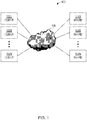
- FIG. 1 is a block diagram illustrating an example of a scalable shard system 100 in which multiple clients can access data items that have been distributed among multiple database shards, according to an embodiment of the invention.
- Shard system 100 includes clients 102A-N and shards 104A-N. The quantities of clients and shards in system 100 can vary.
- Each of shards 104A-N can be a separate and independent database that does not need to be aware of any other shard within system 100.
- Each of shards 104A-N can include a separate database server and relational database, for example.
- Each of clients 102A-N can be a separate computing system that can operate independently of each other of clients 102A-N.
- clients 102A-N can be desktop computers, laptop computers, mobile devices, etc.
- Clients 102A-N can interact with shards 104A-N through a network 106.
- Network 106 can be, or can include, a local area network (LAN), a wide area network (WAN), and/or the Internet. Communication over network 106 can be achieved through a suite of network communication protocols such as Ethernet, Transmission Control Protocol/Internet Protocol (TCP/IP), Hypertext Transfer Protocol (HTTP), Simple Object Access Protocol (SOAP), Open Database Connectivity (ODBC), etc.
- TCP/IP Transmission Control Protocol/Internet Protocol
- HTTP Hypertext Transfer Protocol
- SOAP Simple Object Access Protocol
- ODBC Open Database Connectivity
- Each of clients 102A-N can execute a separate instance of a software program that utilizes a hash function in order to calculate, based on the primary key of a particular data item, the identity of a particular shard, among shards 104A-N, on which that particular data item either has been stored or is to be stored.
- Such data items can be separate records possessing different values for similar attribute sets.
- data items can be stored within shards 104A-N as separate rows within one or more relational database tables. With very specific exceptions discussed below that are applicable to system 100 during rebalancing events, each data item is located on only one of shards 104A-N at any particular moment in time.
- a rebalancing event can potentially cause various data items to be relocated from one shard to another shard.
- the sequence of activities involved in a client's performance of an operation during a rebalancing event can differ from the sequence of activities involved in that client's performance of that same type of operation during "normal" system states occurring outside of a rebalancing event.
- a particular client of clients 102A-N can first determine (e.g., based on the hash function) the shard on which that data item is currently stored. During a rebalancing event, the particular client can perform checks to ensure that the particular client will be operating on the correct copy of the data item, to compensate for the possibility that the data item might have been relocated or deleted asynchronously to the particular client's activities. Although during normal system states only one copy of a data item can exist anywhere in system 100, during a rebalancing event it is possible for multiple copies-different versions-of a data item to be present temporarily within system 100.
- the particular client can make use of version information (discussed in greater detail below) that is stored with each copy of each data item. Based at least in part on such version information, the particular client can ensure that the operation, if performed, will be performed relative to the copy of the data item stored on the shard on which the data item was most recently placed.
- the particular client's performance of the operation during a rebalancing event can involve the creation of a new copy of the data item on a shard separate from the shard on which another copy of the data item previously existed.
- the operation can involve the execution of one or more instructions relative to the data item.
- such instructions can take the form of query language instructions-Structured Query Language (SQL) instructions being just one specific possibility.
- a cleanup operation can be performed to remove old and outdated versions of the data item from shards on which the data item should no longer exist.
- data consistency within system 100 can be maintained in this manner without the use of locks by clients 102A-N.
- system 100 is scalable because shards can be added to (or removed from) system 100.
- the modification of the quantity of shards 104A-N can cause a rebalancing event to occur within system 100.
- rebalancing processes can re-hash each data item's primary key based on the new quantity of shards instead of the old quantity, thereby determining the identity of the shard (different or the same) on which that data item should be located as of the conclusion of the rebalancing event.
- the rebalancing processes can then relocate data items from shard to shard using techniques discussed in greater detail below.
- the relocation can involve the creation and deletion of copies of the data items that would not exist within system 100 outside of the rebalancing event.
- the rebalancing processes can execute asynchronously to software executing on clients 102A-N.
- clients 102A-N can continue to perform operations relative to data items during the rebalancing operation, at least in part by adjusting the sequence of activities that clients 102A-N perform during the rebalancing operation.
- each copy of a particular data item can be stored in association with version information.
- version information can take the form of a system-wide version number that is incremented each time that rebalancing event occurs in system 100.
- version information can take the form of a system-wide version number that is incremented each time that rebalancing event occurs in system 100.
- version information can take the form of a system-wide version number that is incremented each time that rebalancing event occurs in system 100.
- version information can take the form of a system-wide version number that is incremented each time that rebalancing event occurs in system 100.
- a rebalancing process can determine which copy is the older version, and therefore ought to be removed from the shard on which that copy is located.
- Operations that a client performs can involve deleting a data item from a shard.
- a client's performance of a deletion operation relative to a data item does not instantly remove all traces of that data item from the shard on which it was located.
- each data item has an attribute called a "tombstone" whose value can be set to true (if that copy of the data item on that shard has been deleted) or false (if that copy of the data item on that shard has not been deleted).
- system 100 could be in a state in which it is performing a rebalancing event, or system 100 could be in a state outside of such a rebalancing event.
- sequences of activities that clients 102A-N perform as part of operations relative to data items during a rebalancing event can differ from the sequences of activities that clients 102A-N perform as parts of operations of the same type during states in which an rebalancing event is not occurring.
- clients 102A-N may perform operations relative to data items using simple, highly efficient “naive” techniques that may lack safeguards that protect against certain kinds of inconsistencies.
- clients 1 02A-N may perform the same types of operations using more complex, more cautious techniques that impose such safeguards.
- safeguards which might be unnecessary outside of rebalancing events, can be suitable during rebalancing events.
- FIG. 2 is a state diagram that illustrates the various states 200 in which clients 102A-N can exist at various moments in time, and the possible transitions between those states, according to an embodiment of the invention.
- States 200 can include a normal state 202, an enter rebalance state 204, a rebalancing state 206, an enter cleanup state 208, a cleanup state 210, and a leave rebalance state 212.
- clients 102A-N are permitted to perform operations relative to data items stored within shards 104A-N only during normal state 202 and rebalancing state 206, which are likely to be the states in which clients 102A-N are during the vast majority of the time.
- clients 102A-N will usually be in the same state, separate ones of those clients can briefly be in different states during state transitions, as will be seen from the discussion below.
- clients 102A-N can initialize in normal state 202. Clients 102A-N can begin new operations while in normal state 202.
- a notification mechanism can inform each of clients 102A-N that one or more shards have been added to or are going to be removed from system 100. In response to such a notification, each of clients 102A-N can wait for its pending operations to complete, and then that client can transition to enter rebalance state 204. Clients 102A-N do not begin new operations while in enter rebalance state 204; clients 102A-N can queue up operations to be performed.
- each of clients 102A-N can transition to rebalancing state 206.
- rebalancing processes can proceed to move data items from source shards to destination shards.
- the current version number with which new data item copies will become associated from that moment onward, can be incremented upon the entry of clients 102A-N into rebalancing state 206.
- Clients 102A-N can begin new operations (potentially including queued up operations) while in rebalancing state 206.
- a notification mechanism can inform each of clients 102A-N of this fact.
- each of clients 102A-N can wait for its pending operations to complete, and then that client can transition to enter cleanup state 208.
- Clients 102A-N do not begin new operations while in enter cleanup state 208; clients 102A-N can queue up operations to be performed.
- each of clients 102A-N can transition to cleanup state 210.
- rebalancing processes can proceed to remove, from the shards, data item copies that should no longer exist on any shard.
- rebalancing processes can remove, from the shards, all data item copies having a "true" tombstone attribute value. Additionally, in an embodiment, while clients 102AN are in cleanup state 210, rebalancing processes can remove, from the shards, all data item copies having a version number attribute value that is less than the system's current version number. Clients 102A-N do not begin new operations while in cleanup state 210; clients 102AN can queue up operations to be performed. When the rebalancing processes have removed all data item copies that are to be removed, a notification mechanism can inform each of clients 1 02A-N of this fact.
- each of clients 1 02A-N can transition to leave rebalance state 212.
- Clients 102A-N do not begin new operations while in leave rebalance state 212; clients 102A-N can queue up operations to be performed.
- each of clients 102A-N can transition back to normal state 202.
- Clients 102A-N can begin new operations (potentially including queued up operations) while in normal state 202.
- clients 102AN can perform operations in a more cautious manner than then manner in which clients 102A-N would perform the same types of operations while in normal state 202.
- the manner in which clients 102A-N can perform operations while in rebalancing state 206 can guarantee data consistency in spite of the concurrent asynchronous execution of rebalancing processes that may be relocating data items from shard to shard-a concern that does not exist in normal state 202. Discussed below are techniques for performing various different types of operations in this more cautious, consistency-guaranteeing manner while in rebalancing state 206.
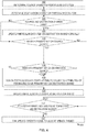
- FIG. 3 is a flow diagram that illustrates an example of a technique 300 for performing an aadd operation while in the rebalancing state, according to an embodiment of the invention.
- technique 300 is illustrated as including specific activities performed in a specific order, alternative embodiments of the invention can involve techniques having additional, fewer, or different activities.
- Any of clients 102A-N can perform technique 300.
- a client can determine the identity of the source shard on which a particular data item would have been located prior to the change in shard quantity. This determination can be achieved, for example, by calculating the particular data item's primary key modulo the old shard quantity.
- the client can determine the identity of the destination shard on which the particular data item is to be located following the change in shard quantity. This determination can be achieved, for example, by calculating the particular data item's primary key modulo the new shard quantity.
- the client can determine whether the identity of the source shard is the same as the identity of the destination shard. If the identities are the same, then control passes to block 308. Otherwise, control passes to block 310.
- the client can add the particular data item to the destination shard in the normal, na ⁇ ve, highly efficient standard manner for performing an add operation. At this point, technique 300 terminates.
- the client can determine whether a data item having the particular data item's primary key already exists on the source shard. If a data item having the particular data item's primary key already exists on the source shard, then control passes to block 312. Otherwise, control passes to block 314.
- the client can conclude that the particular data item duplicates a data item already existing in the shard system, and can refrain from performing the add operation.
- the client can signify to a user that the add operation was prevented due to duplication. At this point, technique 300 terminates.
- the client can determine whether there already exists, on the destination shard, a data item having both (a) the particular data item's primary key and (b) a tombstone attribute value of "true,” If there already exists, on the destination shard, a data item having both (a) the particular data item's primary key and (b) a tombstone attribute value of "true,” then control passes to block 316. Otherwise, control passes to block 320.
- the client can assign, to the attribute values of the data item having the particular data item's primary key (on the destination shard), the attribute values of the particular data item. This assignment essentially updates the data item existing on the destination shard.
- the client can assign the system's current version number to the data item's version number attribute.
- the client can set the tombstone attribute value of the data item having the particular data item's primary key (on the destination shard) to "false.”
- the attribute value assignment of block 316 achieves the same result as that achieved by the activity of block 318, since the particular data item's tombstone attribute value will already be "false" prior to the assignment.
- the client can signify to a user that the add operation succeeded. At this point, technique 300 terminates.
- the client can insert the particular data item into the destination shard.
- the client can assign the system's current version number to the particular data item's version number attribute.
- the client can signify to a user that the add operation succeeded.
- technique 300 terminates.
- the activities of blocks 314-320 are performed as a single atomic operation.
- FIG. 4 is a flow diagram that illustrates an example of a technique 400 for performing an update operation while in the rebalancing state, according to an embodiment of the invention.
- technique 400 is illustrated as including specific activities performed in a specific order, alternative embodiments of the invention can involve techniques having additional, fewer, or different activities.
- Any of clients 102A-N can perform technique 400.
- a client can determine the identity of the source shard on which a particular data item would have been located prior to the change in shard quantity. This determination can be achieved, for example, by calculating the particular data item's primary key modulo the old shard quantity.
- the client can determine the identity of the destination shard on which the particular data item is to be located following the change in shard quantity.
- This determination can be achieved, for example, by calculating the particular data item's primary key modulo the new shard quantity.
- the client can determine whether the identity of the source shard is the same as the identity of the destination shard. If the identities are the same, then control passes to block 408. Otherwise, control passes to block 410.
- the client can update the particular data item on the destination shard in the normal, na ⁇ ve, highly efficient standard manner for performing an update operation.
- technique 400 terminates.
- the client can determine whether a data item having the particular data item's primary key already exists on the source shard. If a data item having the particular data item's primary key already exists on the source shard, then control passes to block 416. Otherwise, control passes to block 422.
- the client can determine whether there already exists, on the destination shard, a data item having the particular data item's primary key. If there already exists, on the destination shard, a data item having the particular data item's primary key, then control passes to block 418. Otherwise, control passes to block 420.
- the client can assign, to the attribute values of the data item having the particular data item's primary key (on the destination shard), the attribute values of the particular data item. This assignment essentially updates the data item existing on the destination shard.
- the client can assign the system's current version number to the data item's version number attribute.
- the client can signify to a user that the update operation succeeded. At this point, technique 400 terminates.
- the client can insert the particular data item into the destination shard.
- the client can assign the system's current version number to the particular data item's version number attribute.
- the client can signify to a user that the update operation succeeded. At this point, technique 400 terminates.
- the client can determine whether there already exists, on the destination shard, a data item having both (a) the particular data item's primary key and (b) a tombstone attribute value of "false.” If there already exists, on the destination shard, a data item having both (a) the particular data item's primary key and (b) a tombstone attribute value of "false,” then control passes to block 418. Otherwise, control passes to block 428.
- the client can refrain from performing the update operation.
- the client can signify to a user that the update operation failed (because there was no data item to update). At this point, technique 400 terminates.
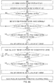
- FIG. 5 is a flow diagram that illustrates an example of a technique 500 for performing a delete operation while in the rebalancing state, according to an embodiment of the invention.
- technique 500 is illustrated as including specific activities performed in a specific order, alternative embodiments of the invention can involve techniques having additional, fewer, or different activities.
- Any of clients 102A-N can perform technique 500.
- a client can determine the identity of the source shard on which a particular data item would have been located prior to the change in shard quantity. This determination can be achieved, for example, by calculating the particular data item's primary key modulo the old shard quantity.
- the client can determine the identity of the destination shard on which the particular data item is to be located following the change in shard quantity.
- This determination can be achieved, for example, by calculating the particular data item's primary key modulo the new shard quantity.
- the client can determine whether the identity of the source shard is the same as the identity of the destination shard. If the identities are the same, then control passes to block 508. Otherwise, control passes to block 510.
- the client can delete the particular data item on the destination shard in the normal, na ⁇ ve, highly efficient standard manner for performing a delete operation.
- technique 500 terminates.
- the client can determine whether a data item having the particular data item's primary key already exists on the source shard. If a data item having the particular data item's primary key already exists on the source shard, then control passes to block 512. Otherwise, control passes to block 516.
- the client can upsert the particular data item into the destination shard.
- An upsert is defined as: (1) an insert if the object identified by the primary key does not exist in the database (i.e., the destination shard), or (2) an update if the object identified by the primary key does exist in the database (i.e., the destination shard).
- the client can set the value of the particular data item's tombstone attribute to "true.”
- the client can assign the system's current version number to the particular data item's version number attribute.
- the client can signify to a user that the delete operation succeeded. At this point, technique 500 terminates.
- the client can determine whether a data item having the particular data item's primary key already exists on the destination shard. If a data item having the particular data item's primary key already exists on the destination shard, then control passes to block 518. Otherwise, control passes to block 520.
- the client can set the value of the data item's tombstone attribute to "true" (on the destination shard).
- the client can assign the system's current version number to the data item's version number attribute.
- the client can signify to a user that the delete operation succeeded.
- technique 500 terminates.
- the client can refrain from performing the delete operation.
- the client can signify to a user that the delete operation failed (because there was no data item to delete). At this point, technique 500 terminates.
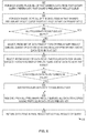
- FIGs. 6A-6B are flow diagrams that illustrate an example of a technique 600 for performing a get operation while in the rebalancing state, according to an embodiment of the invention.
- the get operation can read and return the attribute values of a data item having a client-specified primary key.
- technique 600 is illustrated as including specific activities performed in a specific order, alternative embodiments of the invention can involve techniques having additional, fewer, or different activities. Any of clients 102A-N can perform technique 600. Referring first to FIG. 6A , in block 602, a client can determine the identity of the source shard on which a particular data item having a specified primary key would have been located prior to the change in shard quantity.
- This determination can be achieved, for example, by calculating the specified primary key modulo the old shard quantity.
- the client can determine the identity of the destination shard on which the particular data item having the specified primary key is to be located following the change in shard quantity. This determination can be achieved, for example, by calculating the specified primary key modulo the new shard quantity.
- the client can determine whether the identity of the source shard is the same as the identity of the destination shard. If the identities are the same, then control passes to block 608. Otherwise, control passes to block 610.
- the client can perform a get operation relative to a particular data item having the specified primary key on the destination shard in the normal, na ⁇ ve, highly efficient standard manner for performing a get operation.
- technique 600 terminates.
- the client can determine whether a data item having the specified primary key already exists on the destination shard. If a data item having the specified primary key already exists on the destination shard, then control passes to block 612. Otherwise, control passes to block 618.
- the client can determine whether the data item having the specified primary key on the destination shard has a "true" tombstone attribute value. If the data item having the specified primary key on the destination shard has a "true” tombstone attribute value, then control passes to block 614. Otherwise, control passes to block 616.
- the client can refrain from performing the get operation.
- the client can signify to a user that the get operation failed (because no data item having the specified primary key was found). At this point, technique 600 terminates.
- the client can read the attribute values of the data having the specified primary key on the destination shard.
- the client can present these attribute values to a user, coincidentally signifying that the get operation succeeded.
- technique 600 terminates.
- the client can determine whether a data item having the specified primary key already exists on the source shard. If a data item having the specified primary key already exists on the source shard, then control passes to block 620. Otherwise, control passes to block 626 on FIG. 6B .
- the client can determine whether the data item having the specified primary key on the source shard has a "true" tombstone attribute value. If the data item having the specified primary key on the source shard has a "true” tombstone attribute value, then control passes to block 622. Otherwise, control passes to block 624.
- the client can refrain from performing the get operation.
- the client can signify to a user that the get operation failed (because no data item having the specified primary key was found). At this point, technique 600 terminates.
- the client can read the attribute values of the data having the specified primary key on the source shard.
- the client can present these attribute values to a user, coincidentally signifying that the get operation succeeded. At this point, technique 600 terminates.
- the client can determine (again) whether a data item having the specified primary key now exists on the destination shard. If a data item having the specified primary key now exists on the destination shard (e.g., as a consequence of a rebalancing process having recently moved that data item to the destination shard), then control passes to block 628. Otherwise, control passes to block 630.
- the client can determine whether the data item having the specified primary key on the destination shard has a "true" tombstone attribute value. If the data item having the specified primary key on the destination shard has a "true” tombstone attribute value, then control passes to block 630. Otherwise, control passes to block 632.
- the client can refrain from performing the get operation.
- the client can signify to a user that the get operation failed (because no data item having the specified primary key was found). At this point, technique 600 terminates.
- the client can read the attribute values of the data having the specified primary key on the destination shard.
- the client can present these attribute values to a user, coincidentally signifying that the get operation succeeded. At this point, technique 600 terminates.
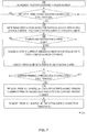
- FIG. 7 is a flow diagram that illustrates an example of a technique 700 for performing a rebalancing operation while clients 102A-N are in the rebalancing state (initially), according to an embodiment of the invention.
- technique 700 is illustrated as including specific activities performed in a specific order, alternative embodiments of the invention can involve techniques having additional, fewer, or different activities.
- Rebalancing processes can perform technique 700 asynchronously to the performance of other types of operations by clients 102AN.
- the system's current version number is incremented.
- a rebalancing process can determine whether any shard still contains a data item whose version number attribute value is less than the system's current version number. If a shard contains a particular data item whose version number attribute value is less than the system's current version number, then control passes to block 706. Otherwise, the rebalancing processes have finished relocating data items for this particular rebalancing event, and control passes to block 714.
- the rebalancing process can determine the identity of the destination shard on which the particular data item is to be located following the change in shard quantity. This determination can be achieved, for example, by calculating the particular data item's primary key modulo the new shard quantity.
- the rebalancing process can determine whether the identity of a source shard, on which the particular data item is currently located, is the same as the identity of the destination shard. If the identities are the same, then control passes to block 710. Otherwise, control passes to block 712.
- the rebalancing process can assign the system's current version number to the particular data item's version number attribute. Under such circumstances, the particular data item does not need to be relocated to a different shard. Control passes back to block 704.
- the rebalancing process can insert the particular data item into the destination shard.
- potential conflicts can be ignored.
- the rebalancing process can assign the system's current version number to the particular data item's version number attribute.
- an old copy of the particular data item can remain on the source shard until the activities of blocks 716 and 718 are performed. Control passes back to block 704.
- the rebalancing process can determine whether any queries (e.g., from clients 102A-N) that had been executing as of the time that the rebalancing processes finished relocating data items are currently executing against any of the shards (e.g., shards 104A-N). If at least one query that had been executing as of the time that the rebalancing processes finished relocating data items is currently executing against at least one shard, then control passes back to block 714. Otherwise, control passes to block 716.
- any queries e.g., from clients 102A-N
- the shards e.g., shards 104A-N
- the rebalancing processes can remove, from all shards, all data item copies whose version number attribute value is less than the system's current version number.
- the rebalancing processes can remove, from all shards, all data item copies whose tombstone attribute values are "true.”
- the activities of blocks 716 and 718 can be performed during cleanup phase 210 discussed above in connection with FIG. 2 .
- FIG. 8 is a flow diagram that illustrates an example of a technique 800 for performing a query operation while in the rebalancing state, according to an embodiment of the invention.
- technique 800 is illustrated as including specific activities performed in a specific order, alternative embodiments of the invention can involve techniques having additional, fewer, or different activities. Any of clients 102A-N can perform technique 800, for example.
- Technique 800 can be performed concurrently with technique 700.
- block 802 for each particular shard of shards 104A-N, all of the particular shard's data items that satisfy query-specified filtering criteria can be placed in a separate preliminary result queue for that particular shard. Each such preliminary result queue can start out empty.
- a separate preliminary result queue may be populated for each of shards 104A-N.
- the data items contained within that particular shard's preliminary result queue can be sorted based at least in part on those data items' primary keys.
- each preliminary result queue can contain data items that are sorted such that the data item having the smallest primary key of data items in that preliminary result queue can be at the front of that preliminary result queue.
- a determination can be made as to whether all of the shards' preliminary result queues are empty. If all of the shards' preliminary result queues are empty, then control passes to block 818. Otherwise, control passes to block 808.
- a subset of one or more data items having the smallest primary key among data items in that set can be selected.
- a particular data item having the largest version number attribute value can be selected.
- a determination can be made as to whether the particular data item's tombstone attribute value is "false.” If the particular data item's tombstone attribute value is "false,” then control passes to block 814. Otherwise, control passes to block 816.
- the particular data item can be added to a final result set.
- the final result set can start out empty.
- Control passes to block 816.
- all data item copies having the same primary key as the particular data item (including the particular data item itself) can be removed from all of the shards' preliminary result queues. This removal potentially can cause other data items to rise to the top of one or more of those queues. Control passes back to block 806.
- the data items in the final result set can be returned as the final results of the query operation.
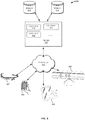
- FIG. 9 depicts a simplified diagram of a distributed system 900 for implementing one of the embodiments.
- distributed system 900 includes one or more client computing devices 902, 904, 906, and 908, which are configured to execute and operate a client application such as a web browser, proprietary client (e.g., Oracle Forms), or the like over one or more network(s) 910.
- Server 912 may be communicatively coupled with remote client computing devices 902, 904, 906, and 908 via network 910.
- server 912 may be adapted to run one or more services or software applications provided by one or more of the components of the system.
- these services may be offered as web-based or cloud services or under a Software as a Service (SaaS) model to the users of client computing devices 902, 904, 906, and/or 908.
- SaaS Software as a Service
- Users operating client computing devices 902, 904, 906, and/or 908 may in turn utilize one or more client applications to interact with server 912 to utilize the services provided by these components.
- the software components 918, 920 and 922 of system 900 are shown as being implemented on server 912.
- one or more of the components of system 900 and/or the services provided by these components may also be implemented by one or more of the client computing devices 902, 904, 906, and/or 908. Users operating the client computing devices may then utilize one or more client applications to use the services provided by these components.
- These components may be implemented in hardware, firmware, software, or combinations thereof. It should be appreciated that various different system configurations are possible, which may be different from distributed system 900.
- the embodiment shown in the figure is thus one example of a distributed system for implementing an embodiment system and is not intended to be limiting.
- Client computing devices 902, 904, 906, and/or 908 may be portable handheld devices (e.g., an iPhone®, cellular telephone, an iPad®, computing tablet, a personal digital assistant (PDA)) or wearable devices (e.g., a Google Glass® head mounted display), running software such as Microsoft Windows Mobile®, and/or a variety of mobile operating systems such as iOS, Windows Phone, Android, BlackBerry 10, Palm OS, and the like, and being Internet, e-mail, short message service (SMS), Blackberry®, or other communication protocol enabled.
- the client computing devices can be general purpose personal computers including, by way of example, personal computers and/or laptop computers running various versions of Microsoft Windows®, Apple Macintosh®, and/or Linux operating systems.
- the client computing devices can be workstation computers running any of a variety of commercially-available UNIX® or UNIX-like operating systems, including without limitation the variety of GNU/Linux operating systems, such as for example, Google Chrome OS.
- client computing devices 902, 904, 906, and 908 may be any other electronic device, such as a thin-client computer, an Internet-enabled gaming system (e.g., a Microsoft Xbox gaming console with or without a Kinect® gesture input device), and/or a personal messaging device, capable of communicating over network(s) 910.
- exemplary distributed system 900 is shown with four client computing devices, any number of client computing devices may be supported. Other devices, such as devices with sensors, etc., may interact with server 912.
- Network(s) 910 in distributed system 900 may be any type of network familiar to those skilled in the art that can support data communications using any of a variety of commercially-available protocols, including without limitation TCP/IP (transmission control protocol/Internet protocol), SNA (systems network architecture), IPX (Internet packet exchange), AppleTalk, and the like.
- network(s) 910 can be a local area network (LAN), such as one based on Ethernet, Token-Ring and/or the like.
- LAN local area network
- Network(s) 910 can be a wide-area network and the Internet.
- a virtual network including without limitation a virtual private network (VPN), an intranet, an extranet, a public switched telephone network (PSTN), an infrared network, a wireless network (e.g., a network operating under any of the Institute of Electrical and Electronics (IEEE) 902.11 suite of protocols, Bluetooth®, and/or any other wireless protocol); and/or any combination of these and/or other networks.
- VPN virtual private network
- PSTN public switched telephone network
- IEEE Institute of Electrical and Electronics
- Server 912 may be composed of one or more general purpose computers, specialized server computers (including, by way of example, PC (personal computer) servers, UNIX® servers, mid-range servers, mainframe computers, rack-mounted servers, etc.), server farms, server clusters, or any other appropriate arrangement and/or combination.
- server 912 may be adapted to run one or more services or software applications described in the foregoing disclosure.
- server 912 may correspond to a server for performing processing described above according to an embodiment of the present disclosure.
- Server 912 may run an operating system including any of those discussed above, as well as any commercially available server operating system. Server 912 may also run any of a variety of additional server applications and/or mid-tier applications, including HTTP (hypertext transport protocol) servers, FTP (file transfer protocol) servers, CGI (common gateway interface) servers, JAVA® servers, database servers, and the like. Exemplary database servers include without limitation those commercially available from Oracle, Microsoft, Sybase, IBM (International Business Machines), and the like.
- server 912 may include one or more applications to analyze and consolidate data feeds and/or event updates received from users of client computing devices 902, 904, 906, and 908.
- data feeds and/or event updates may include, but are not limited to, Twitter® feeds, Facebook® updates or real-time updates received from one or more third party information sources and continuous data streams, which may include real-time events related to sensor data applications, financial tickers, network performance measuring tools (e.g., network monitoring and traffic management applications), clickstream analysis tools, automobile traffic monitoring, and the like.
- Server 912 may also include one or more applications to display the data feeds and/or real-time events via one or more display devices of client computing devices 902, 904, 906, and 908.
- Distributed system 900 may also include one or more databases 914 and 916.
- Databases 914 and 916 may reside in a variety of locations.
- one or more of databases 914 and 916 may reside on a non-transitory storage medium local to (and/or resident in) server 912.
- databases 914 and 916 may be remote from server 912 and in communication with server 912 via a network-based or dedicated connection.
- databases 914 and 916 may reside in a storage-area network (SAN).
- SAN storage-area network
- any necessary files for performing the functions attributed to server 912 may be stored locally on server 912 and/or remotely, as appropriate.
- databases 914 and 916 may include relational databases, such as databases provided by Oracle, which are adapted to store, update, and retrieve data in response to SQL-formatted commands.
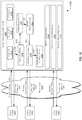
- FIG. 10 is a simplified block diagram of one or more components of a system environment 1000 by which services provided by one or more components of an embodiment system may be offered as cloud services, in accordance with an embodiment of the present disclosure.
- system environment 1000 includes one or more client computing devices 1004, 1006, and 1008 that may be used by users to interact with a cloud infrastructure system 1002 that provides cloud services.
- the client computing devices may be configured to operate a client application such as a web browser, a proprietary client application (e.g., Oracle Forms), or some other application, which may be used by a user of the client computing device to interact with cloud infrastructure system 1002 to use services provided by cloud infrastructure system 1002.
- a proprietary client application e.g., Oracle Forms
- cloud infrastructure system 1002 depicted in the figure may have other components than those depicted. Further, the embodiment shown in the figure is only one example of a cloud infrastructure system that may incorporate an embodiment of the invention. In some other embodiments, cloud infrastructure system 1002 may have more or fewer components than shown in the figure, may combine two or more components, or may have a different configuration or arrangement of components.
- Client computing devices 1004, 1006, and 1008 may be devices similar to those described above for 902, 904, 906, and 908.
- exemplary system environment 1000 is shown with three client computing devices, any number of client computing devices may be supported. Other devices such as devices with sensors, etc. may interact with cloud infrastructure system 1002.
- Network(s) 1010 may facilitate communications and exchange of data between clients 1004, 1006, and 1008 and cloud infrastructure system 1002.
- Each network may be any type of network familiar to those skilled in the art that can support data communications using any of a variety of commercially-available protocols, including those described above for network(s) 910.
- Cloud infrastructure system 1002 may comprise one or more computers and/or servers that may include those described above for server 912.
- services provided by the cloud infrastructure system may include a host of services that are made available to users of the cloud infrastructure system on demand, such as online data storage and backup solutions, Web-based e-mail services, hosted office suites and document collaboration services, database processing, managed technical support services, and the like. Services provided by the cloud infrastructure system can dynamically scale to meet the needs of its users.
- a specific instantiation of a service provided by cloud infrastructure system is referred to herein as a "service instance.”
- any service made available to a user via a communication network, such as the Internet, from a cloud service provider's system is referred to as a "cloud service.”
- a cloud service provider's system may host an application, and a user may, via a communication network such as the Internet, on demand, order and use the application.
- a service in a computer network cloud infrastructure may include protected computer network access to storage, a hosted database, a hosted web server, a software application, or other service provided by a cloud vendor to a user, or as otherwise known in the art.
- a service can include password-protected access to remote storage on the cloud through the Internet.
- a service can include a web service-based hosted relational database and a script-language middleware engine for private use by a networked developer.
- a service can include access to an email software application hosted on a cloud vendor's web site.
- cloud infrastructure system 1002 may include a suite of applications, middleware, and database service offerings that are delivered to a customer in a self-service, subscription-based, elastically scalable, reliable, highly available, and secure manner.
- An example of such a cloud infrastructure system is the Oracle Public Cloud provided by the present assignee.
- cloud infrastructure system 1002 may be adapted to automatically provision, manage and track a customer's subscription to services offered by cloud infrastructure system 1002.
- Cloud infrastructure system 1002 may provide the cloud services via different deployment models.
- services may be provided under a public cloud model in which cloud infrastructure system 1002 is owned by an organization selling cloud services (e.g., owned by Oracle) and the services are made available to the general public or different industry enterprises.
- services may be provided under a private cloud model in which cloud infrastructure system 1002 is operated solely for a single organization and may provide services for one or more entities within the organization.
- the cloud services may also be provided under a community cloud model in which cloud infrastructure system 1002 and the services provided by cloud infrastructure system 1002 are shared by several organizations in a related community.
- the cloud services may also be provided under a hybrid cloud model, which is a combination of two or more different models.
- the services provided by cloud infrastructure system 1002 may include one or more services provided under Software as a Service (SaaS) category, Platform as a Service (PaaS) category, Infrastructure as a Service (IaaS) category, or other categories of services including hybrid services.
- SaaS Software as a Service
- PaaS Platform as a Service
- IaaS Infrastructure as a Service
- a customer via a subscription order, may order one or more services provided by cloud infrastructure system 1002.
- Cloud infrastructure system 1002 then performs processing to provide the services in the customer's subscription order.
- the services provided by cloud infrastructure system 1002 may include, without limitation, application services, platform services and infrastructure services.
- application services may be provided by the cloud infrastructure system via a SaaS platform.
- the SaaS platform may be configured to provide cloud services that fall under the SaaS category.
- the SaaS platform may provide capabilities to build and deliver a suite of on-demand applications on an integrated development and deployment platform.
- the SaaS platform may manage and control the underlying software and infrastructure for providing the SaaS services.
- customers can utilize applications executing on the cloud infrastructure system.
- Customers can acquire the application services without the need for customers to purchase separate licenses and support.
- Various different SaaS services may be provided. Examples include, without limitation, services that provide solutions for sales performance management, enterprise integration, and business flexibility for large organizations.
- platform services may be provided by the cloud infrastructure system via a PaaS platform.
- the PaaS platform may be configured to provide cloud services that fall under the PaaS category.
- Examples of platform services may include without limitation services that enable organizations (such as Oracle) to consolidate existing applications on a shared, common architecture, as well as the ability to build new applications that leverage the shared services provided by the platform.
- the PaaS platform may manage and control the underlying software and infrastructure for providing the PaaS services. Customers can acquire the PaaS services provided by the cloud infrastructure system without the need for customers to purchase separate licenses and support.
- Examples of platform services include, without limitation, Oracle Java Cloud Service (JCS), Oracle Database Cloud Service (DBCS), and others.
- platform services provided by the cloud infrastructure system may include database cloud services, middleware cloud services (e.g., Oracle Fusion Middleware services), and Java cloud services.
- database cloud services may support shared service deployment models that enable organizations to pool database resources and offer customers a Database as a Service in the form of a database cloud.
- middleware cloud services may provide a platform for customers to develop and deploy various business applications
- Java cloud services may provide a platform for customers to deploy Java applications, in the cloud infrastructure system.
- infrastructure services may be provided by an IaaS platform in the cloud infrastructure system.
- the infrastructure services facilitate the management and control of the underlying computing resources, such as storage, networks, and other fundamental computing resources for customers utilizing services provided by the SaaS platform and the PaaS platform.
- cloud infrastructure system 1002 may also include infrastructure resources 1030 for providing the resources used to provide various services to customers of the cloud infrastructure system.
- infrastructure resources 1030 may include pre-integrated and optimized combinations of hardware, such as servers, storage, and networking resources to execute the services provided by the PaaS platform and the SaaS platform.
- resources in cloud infrastructure system 1002 may be shared by multiple users and dynamically re-allocated per demand. Additionally, resources may be allocated to users in different time zones. For example, cloud infrastructure system 1030 may enable a first set of users in a first time zone to utilize resources of the cloud infrastructure system for a specified number of hours and then enable the re-allocation of the same resources to another set of users located in a different time zone, thereby maximizing the utilization of resources.
- a number of internal shared services 1032 may be provided that are shared by different components or modules of cloud infrastructure system 1002 and by the services provided by cloud infrastructure system 1002.
- These internal shared services may include, without limitation, a security and identity service, an integration service, an enterprise repository service, an enterprise manager service, a virus scanning and white list service, a high availability, backup and recovery service, service for enabling cloud support, an email service, a notification service, a file transfer service, and the like.
- cloud infrastructure system 1002 may provide comprehensive management of cloud services (e.g., SaaS, PaaS, and IaaS services) in the cloud infrastructure system.
- cloud management functionality may include capabilities for provisioning, managing and tracking a customer's subscription received by cloud infrastructure system 1002, and the like.
- cloud management functionality may be provided by one or more modules, such as an order management module 1020, an order orchestration module 1022, an order provisioning module 1024, an order management and monitoring module 1026, and an identity management module 1028.
- modules may include or be provided using one or more computers and/or servers, which may be general purpose computers, specialized server computers, server farms, server clusters, or any other appropriate arrangement and/or combination.
- a customer using a client device may interact with cloud infrastructure system 1002 by requesting one or more services provided by cloud infrastructure system 1002 and placing an order for a subscription for one or more services offered by cloud infrastructure system 1002.
- the customer may access a cloud User Interface (UI), cloud UI 1012, cloud UI 1014 and/or cloud UI 1016 and place a subscription order via these UIs.
- UI cloud User Interface
- the order information received by cloud infrastructure system 1002 in response to the customer placing an order may include information identifying the customer and one or more services offered by the cloud infrastructure system 1002 that the customer intends to subscribe to.
- the order information is received via the cloud UIs, 1012, 1014 and/or 1016.
- Order database 1018 can be one of several databases operated by cloud infrastructure system 1018 and operated in conjunction with other system elements.
- order management module 1020 may be configured to perform billing and accounting functions related to the order, such as verifying the order, and upon verification, booking the order.
- Order orchestration module 1022 may utilize the order information to orchestrate the provisioning of services and resources for the order placed by the customer. In some instances, order orchestration module 1022 may orchestrate the provisioning of resources to support the subscribed services using the services of order provisioning module 1024.
- order orchestration module 1022 enables the management of business processes associated with each order and applies business logic to determine whether an order should proceed to provisioning.
- order orchestration module 1022 sends a request to order provisioning module 1024 to allocate resources and configure those resources needed to fulfill the subscription order.
- order provisioning module 1024 enables the allocation of resources for the services ordered by the customer.
- Order provisioning module 1024 provides a level of abstraction between the cloud services provided by cloud infrastructure system 1000 and the physical implementation layer that is used to provision the resources for providing the requested services. Order orchestration module 1022 may thus be isolated from implementation details, such as whether or not services and resources are actually provisioned on the fly or pre-provisioned and only allocated/assigned upon request.
- a notification of the provided service may be sent to customers on client devices 1004, 1006 and/or 1008 by order provisioning module 1024 of cloud infrastructure system 1002.
- order management and monitoring module 1026 may be configured to collect usage statistics for the services in the subscription order, such as the amount of storage used, the amount data transferred, the number of users, and the amount of system up time and system down time.
- cloud infrastructure system 1000 may include an identity management module 1028.
- Identity management module 1028 may be configured to provide identity services, such as access management and authorization services in cloud infrastructure system 1000.
- identity management module 1028 may control information about customers who wish to utilize the services provided by cloud infrastructure system 1002. Such information can include information that authenticates the identities of such customers and information that describes which actions those customers are authorized to perform relative to various system resources (e.g., files, directories, applications, communication ports, memory segments, etc.)
- Identity management module 1028 may also include the management of descriptive information about each customer and about how and by whom that descriptive information can be accessed and modified.
- FIG. 11 illustrates an example computer system 1100 in which various embodiments of the present invention may be implemented.
- the system 1100 may be used to implement any of the computer systems described above.
- computer system 1100 includes a processing unit 1104 that communicates with a number of peripheral subsystems via a bus subsystem 1102. These peripheral subsystems may include a processing acceleration unit 1106, an I/O subsystem 1108, a storage subsystem 1118 and a communications subsystem 1124.
- Storage subsystem 1118 includes tangible computer-readable storage media 1122 and a system memory 1110.
- Bus subsystem 1102 provides a mechanism for letting the various components and subsystems of computer system 1100 communicate with each other as intended.
- Bus subsystem 1102 is shown schematically as a single bus, alternative embodiments of the bus subsystem may utilize multiple buses.
- Bus subsystem 1102 may be any of several types of bus structures including a memory bus or memory controller, a peripheral bus, and a local bus using any of a variety of bus architectures.
- bus architectures may include an Industry Standard Architecture (ISA) bus, Micro Channel Architecture (MCA) bus, Enhanced ISA (EISA) bus, Video Electronics Standards Association (VESA) local bus, and Peripheral Component Interconnect (PCI) bus, which can be implemented as a Mezzanine bus manufactured to the IEEE P1386.1 standard.
- ISA Industry Standard Architecture
- MCA Micro Channel Architecture
- EISA Enhanced ISA
- VESA Video Electronics Standards Association
- PCI Peripheral Component Interconnect
- Processing unit 1104 which can be implemented as one or more integrated circuits (e.g., a conventional microprocessor or microcontroller), controls the operation of computer system 1100.
- processors may be included in processing unit 1104. These processors may include single core or multicore processors.
- processing unit 1104 may be implemented as one or more independent processing units 1132 and/or 1134 with single or multicore processors included in each processing unit. In other embodiments, processing unit 1104 may also be implemented as a quad-core processing unit formed by integrating two dual-core processors into a single chip.
- processing unit 1104 can execute a variety of programs in response to program code and can maintain multiple concurrently executing programs or processes. At any given time, some or all of the program code to be executed can be resident in processor(s) 1104 and/or in storage subsystem 1118. Through suitable programming, processor(s) 1104 can provide various functionalities described above.
- Computer system 1100 may additionally include a processing acceleration unit 1106, which can include a digital signal processor (DSP), a special-purpose processor, and/or the like.
- DSP digital signal processor
- I/O subsystem 1108 may include user interface input devices and user interface output devices.
- User interface input devices may include a keyboard, pointing devices such as a mouse or trackball, a touchpad or touch screen incorporated into a display, a scroll wheel, a click wheel, a dial, a button, a switch, a keypad, audio input devices with voice command recognition systems, microphones, and other types of input devices.
- User interface input devices may include, for example, motion sensing and/or gesture recognition devices such as the Microsoft Kinect® motion sensor that enables users to control and interact with an input device, such as the Microsoft Xbox® 360 game controller, through a natural user interface using gestures and spoken commands.
- User interface input devices may also include eye gesture recognition devices such as the Google Glass® blink detector that detects eye activity (e.g., 'blinking' while taking pictures and/or making a menu selection) from users and transforms the eye gestures as input into an input device (e.g., Google Glass®). Additionally, user interface input devices may include voice recognition sensing devices that enable users to interact with voice recognition systems (e.g., Siri® navigator), through voice commands.
- eye gesture recognition devices such as the Google Glass® blink detector that detects eye activity (e.g., 'blinking' while taking pictures and/or making a menu selection) from users and transforms the eye gestures as input into an input device (e.g., Google Glass®).
- user interface input devices may include voice recognition sensing devices that enable users to interact with voice recognition systems (e.g., Siri® navigator), through voice commands.
- voice recognition systems e.g., Siri® navigator
- User interface input devices may also include, without limitation, three dimensional (3D) mice, joysticks or pointing sticks, gamepads and graphic tablets, and audio/visual devices such as speakers, digital cameras, digital camcorders, portable media players, webcams, image scanners, fingerprint scanners, barcode reader 3D scanners, 3D printers, laser rangefinders, and eye gaze tracking devices.
- user interface input devices may include, for example, medical imaging input devices such as computed tomography, magnetic resonance imaging, position emission tomography, medical ultrasonography devices.
- User interface input devices may also include, for example, audio input devices such as MIDI keyboards, digital musical instruments and the like.
- User interface output devices may include a display subsystem, indicator lights, or non-visual displays such as audio output devices, etc.
- the display subsystem may be a cathode ray tube (CRT), a flat-panel device, such as that using a liquid crystal display (LCD) or plasma display, a projection device, a touch screen, and the like.
- CTR cathode ray tube
- LCD liquid crystal display
- plasma display a projection device
- touch screen a touch screen
- output device is intended to include all possible types of devices and mechanisms for outputting information from computer system 1100 to a user or other computer.
- user interface output devices may include, without limitation, a variety of display devices that visually convey text, graphics and audio/video information such as monitors, printers, speakers, headphones, automotive navigation systems, plotters, voice output devices, and modems.
- Computer system 1100 may comprise a storage subsystem 1118 that comprises software elements, shown as being currently located within a system memory 1110.
- System memory 1110 may store program instructions that are loadable and executable on processing unit 1104, as well as data generated during the execution of these programs.
- system memory 1110 may be volatile (such as random access memory (RAM)) and/or non-volatile (such as read-only memory (ROM), flash memory, etc.)
- RAM random access memory
- ROM read-only memory
- system memory 1110 may include multiple different types of memory, such as static random access memory (SRAM) or dynamic random access memory (DRAM).
- SRAM static random access memory
- DRAM dynamic random access memory
- BIOS basic input/output system
- BIOS basic input/output system
- BIOS basic routines that help to transfer information between elements within computer system 1100, such as during start-up, may typically be stored in the ROM.
- system memory 1110 also illustrates application programs 1112, which may include client applications, Web browsers, mid-tier applications, relational database management systems (RDBMS), etc., program data 1114, and an operating system 1116.
- operating system 1116 may include various versions of Microsoft Windows®, Apple Macintosh®, and/or Linux operating systems, a variety of commercially-available UNIX® or UNIX-like operating systems (including without limitation the variety of GNU/Linux operating systems, the Google Chrome® OS, and the like) and/or mobile operating systems such as iOS, Windows® Phone, Android® OS, BlackBerry® 11 OS, and Palm® OS operating systems.
- Storage subsystem 1118 may also provide a tangible computer-readable storage medium for storing the basic programming and data constructs that provide the functionality of some embodiments.
- Software programs, code modules, instructions that when executed by a processor provide the functionality described above may be stored in storage subsystem 1118. These software modules or instructions may be executed by processing unit 1104.
- Storage subsystem 1118 may also provide a repository for storing data used in accordance with the present invention.
- Storage subsystem 1100 may also include a computer-readable storage media reader 1120 that can further be connected to computer-readable storage media 1122. Together and, optionally, in combination with system memory 1110, computer-readable storage media 1122 may comprehensively represent remote, local, fixed, and/or removable storage devices plus storage media for temporarily and/or more permanently containing, storing, transmitting, and retrieving computer-readable information.
- Computer-readable storage media 1122 containing code, or portions of code can also include any appropriate media known or used in the art, including storage media and communication media, such as but not limited to, volatile and non-volatile, removable and non-removable media implemented in any method or technology for storage and/or transmission of information.
- This can include tangible computer-readable storage media such as RAM, ROM, electronically erasable programmable ROM (EEPROM), flash memory or other memory technology, CD-ROM, digital versatile disk (DVD), or other optical storage, magnetic cassettes, magnetic tape, magnetic disk storage or other magnetic storage devices, or other tangible computer readable media.
- This can also include nontangible computer-readable media, such as data signals, data transmissions, or any other medium which can be used to transmit the desired information and which can be accessed by computing system 1100.
- computer-readable storage media 1122 may include a hard disk drive that reads from or writes to non-removable, nonvolatile magnetic media, a magnetic disk drive that reads from or writes to a removable, nonvolatile magnetic disk, and an optical disk drive that reads from or writes to a removable, nonvolatile optical disk such as a CD ROM, DVD, and Blu-Ray® disk, or other optical media.
- Computer-readable storage media 1122 may include, but is not limited to, Zip® drives, flash memory cards, universal serial bus (USB) flash drives, secure digital (SD) cards, DVD disks, digital video tape, and the like.
- Computer-readable storage media 1122 may also include, solid-state drives (SSD) based on non-volatile memory such as flash-memory based SSDs, enterprise flash drives, solid state ROM, and the like, SSDs based on volatile memory such as solid state RAM, dynamic RAM, static RAM, DRAM-based SSDs, magnetoresistive RAM (MRAM) SSDs, and hybrid SSDs that use a combination of DRAM and flash memory based SSDs.
- SSD solid-state drives
- volatile memory such as solid state RAM, dynamic RAM, static RAM, DRAM-based SSDs, magnetoresistive RAM (MRAM) SSDs, and hybrid SSDs that use a combination of DRAM and flash memory based SSDs.
- MRAM magnetoresistive RAM
- hybrid SSDs that use a combination of DRAM and flash memory based SSDs.
- the disk drives and their associated computer-readable media may provide non-volatile storage of computer-readable instructions, data structures, program modules, and other data for computer system 1100.
- Communications subsystem 1124 provides an interface to other computer systems and networks. Communications subsystem 1124 serves as an interface for receiving data from and transmitting data to other systems from computer system 1100. For example, communications subsystem 1124 may enable computer system 1100 to connect to one or more devices via the Internet.
- communications subsystem 1124 can include radio frequency (RF) transceiver components for accessing wireless voice and/or data networks (e.g., using cellular telephone technology, advanced data network technology, such as 3G, 4G or EDGE (enhanced data rates for global evolution), WiFi (IEEE 802.11 family standards, or other mobile communication technologies, or any combination thereof), global positioning system (GPS) receiver components, and/or other components.
- RF radio frequency
- communications subsystem 1124 can provide wired network connectivity (e.g., Ethernet) in addition to or instead of a wireless interface.
- communications subsystem 1124 may also receive input communication in the form of structured and/or unstructured data feeds 1126, event streams 1128, event updates 1130, and the like on behalf of one or more users who may use computer system 1100.
- communications subsystem 1124 may be configured to receive data feeds 1126 in real-time from users of social networks and/or other communication services such as Twitter® feeds, Facebook® updates, web feeds such as Rich Site Summary (RSS) feeds, and/or real-time updates from one or more third party information sources.
- RSS Rich Site Summary
- communications subsystem 1124 may also be configured to receive data in the form of continuous data streams, which may include event streams 1128 of real-time events and/or event updates 1130, which may be continuous or unbounded in nature with no explicit end.
- applications that generate continuous data may include, for example, sensor data applications, financial tickers, network performance measuring tools (e.g. network monitoring and traffic management applications), clickstream analysis tools, automobile traffic monitoring, and the like.
- Communications subsystem 1124 may also be configured to output the structured and/or unstructured data feeds 1126, event streams 1128, event updates 1130, and the like to one or more databases that may be in communication with one or more streaming data source computers coupled to computer system 1100.
- Computer system 1100 can be one of various types, including a handheld portable device (e.g., an iPhone® cellular phone, an iPad® computing tablet, a PDA), a wearable device (e.g., a Google Glass® head mounted display), a PC, a workstation, a mainframe, a kiosk, a server rack, or any other data processing system.
- a handheld portable device e.g., an iPhone® cellular phone, an iPad® computing tablet, a PDA
- a wearable device e.g., a Google Glass® head mounted display
- PC personal computer
- workstation e.g., a workstation
- mainframe e.g., a mainframe
- kiosk e.g., a server rack
- server rack e.g., a server rack, or any other data processing system.
Description
- A portion of the disclosure of this patent document contains material which is subject to copyright protection. The copyright owner has no objection to the facsimile reproduction by anyone of the patent document or the patent disclosure, as it appears in the Patent and Trademark Office patent file or records, but otherwise reserves all copyright rights whatsoever.
- In a system of database shards, data items, such as records or rows or documents, can be distributed among multiple separate, independent databases, called shards. In such a system, data items typically are not, and are not permitted to be, duplicated among the shards. Thus, in such a system, a particular data item will be located on only one of the several shards at any given time. In order for a client to determine which of the several shards contains the particular data item, the client can input the data item's primary key-which uniquely identifies the particular data item-into a hash function. The hash function computes, based on the primary key, the identity of the shard on which the particular data item is currently stored. For example, a hash function might divide a numeric primary key by the quantity of shards in the system and then take the remainder (essentially a modulo operation) to be the identifier for the shard that contains the particular data item. Using such a hash function to determine, in the first place, the shard on which each data item will be stored typically causes data items to be distributed relatively evenly among the shards.
- Once the client has identified the shard upon which a particular data item is located, the client can perform operations, such as read, delete, or update operations, relative to the data item. Usually, a shard system will serve numerous clients concurrently, and these clients may each perform, asynchronously to each other, operations relative to separate data items. Potentially, multiple clients could inadvertently attempt to perform operations relative to the same data item simultaneously. If this scenario were permitted to occur unhindered, then the data item could become corrupted, making the state of the shard system inconsistent. Under one approach, in order to guarantee that multiple clients will not concurrently perform operations relative to the same data item, a client that seeks to perform an operation relative to a particular data item can first be required to acquire an exclusive lock on that particular data item. Each data item can be associated with a separate lock. A client is prevented from acquiring the exclusive lock on the particular data item if another client already holds that exclusive lock; under such circumstances, the client seeking to obtain the exclusive lock must wait for the lock-holding client to release the exclusive lock. While a client is holding the exclusive lock on a particular data item, that client alone can perform operations relative to the particular data item. When the client has finished performing operations relative to the particular data item, the client can release the exclusive lock on the particular data item, thereby making the particular data item available for access by other clients.
- As the quantity of data stored within the shard system grows, the capacity of the existing shards in the system might become inadequate to contain all of the data that is going to be stored in the system. It can be desirable, under those circumstances, to add one or more new shards to the system. The addition of new shards can involve the addition of new hardware computing and storage devices to contain and manage new databases. In order to attempt to balance the client access load among the shards, so that no one subset of shards becomes disproportionately burdened with client requests, the addition of new shards to the system can precipitate a redistribution of the system's stored data items among the augmented group of shards. The redistribution event, or rebalancing event, can cause data items that were formerly shards. The redistribution event, or rebalancing event, can cause data items that were formerly stored on one shard to be re-located to another shard-potentially, but not necessarily, to a newly added shard. Under one approach, rebalancing processes can obtain exclusive locks on the data items that are to be moved. After obtaining the exclusive locks on the data items, the rebalancing processes can move those data items from old shards to the new shards that have been determined by a revised hash function to be the destination for those data items. After moving the data items, the rebalancing processes can release the exclusive locks on those data items.
- For as long as exclusive locks have existed, some drawbacks have attended their uses. One drawback is that while a data item's exclusive lock is held by a process, no other process can access that data item. Thus, under the lock-using rebalancing approach discussed above, clients may be largely unable to perform operations relative to the shard system while the rebalancing event proceeds; no client can obtain an exclusive lock on a data item while a rebalancing process holds that exclusive lock. Even when the rebalancing event is not ongoing, the overhead involved in clients' acquisition, maintenance, and release of locks-to guard against concurrent multiple client access-can be significant and burdensome. Even ignoring the effects of rebalancing events, the use of locks within a shard system can negatively impact system efficiency and performance. Perhaps worse still, unexpected failures within the shard system can cause a lock-holding process (which could be, for example, a client or a rebalancing process) to freeze up or otherwise quit functioning properly. Under such circumstances, the non-functional process may retain an exclusive lock on a particular data item until some timer expires, at which time the non-functional process may be terminated, and the locks it held forcibly released. Other processes, including clients and rebalancing processes, are consequently forced to wait for the timer's expiration before proceeding with their intended tasks relative to that particular data item. Especially if the operations to be performed relative to the particular data item are just one step within a strictly ordered sequence of operations to be performed relative to multiple separate data items, such forced waiting can cause the performance of the entire shard system to degrade noticeably. Dependencies imposed by orders in which operations often need to be performed can cause these kinds of complications to cascade.
-
US 2011/0282832 A1 describes load balancing in parallel database systems using multi-reordering , in which a sequence of multiple processers that have small average load is selected to participate in load balancing. -
-
FIG. 1 is a block diagram illustrating an example of a scalable shard system in which multiple clients can access data items that have been distributed among multiple database shards, according to an embodiment of the invention; -
FIG. 2 is a state diagram that illustrates the various states in which system can exist at various moments in time, and the possible transitions between those states, according to an embodiment of the invention; -
FIG. 3 is a flow diagram that illustrates an example of a technique for performing an add operation while in the rebalancing state, according to an embodiment of the invention; -
FIG. 4 is a flow diagram that illustrates an example of a technique for performing an update operation while in the rebalancing state, according to an embodiment of the invention; -
FIG. 5 is a flow diagram that illustrates an example of a technique for performing a delete operation while in the rebalancing state, according to an embodiment of the invention; -
FIGs. 6A-6B are flow diagrams that illustrate an example of a technique for performing a get operation while in the rebalancing state, according to an embodiment of the invention; -
FIG. 7 is a flow diagram that illustrates an example of a technique for performing a rebalancing operation while in the rebalancing state (initially), according to an embodiment of the invention; -
FIG. 8 is a flow diagram that illustrates an example of a technique for performing a query operation while in the rebalancing state, according to an embodiment of the invention; -
FIG. 9 depicts a simplified diagram of a distributed system for implementing one of the embodiments. -
FIG. 10 is a simplified block diagram of components of a system environment by which services provided by the components of an embodiment system may be offered as cloud services, in accordance with an embodiment of the present disclosure. -
FIG. 11 illustrates an example of a computer system in which various embodiments of the present invention may be implemented. - In the following description, for the purposes of explanation, specific details are set forth in order to provide a thorough understanding of embodiments of the invention. However, it will be apparent that the invention may be practiced without these specific details.
- According to an embodiment of the invention, multiple clients can be enabled to perform operations relative to data items in a shard system asynchronously to each other without the use by those clients of exclusive locks. Furthermore, according to an embodiment of the invention, a rebalancing event, in which data items are redistributed automatically among a set of shards due to a modification (addition or impending removal) of the quantity of shards in the system, can be performed without the use of exclusive locks by clients. Additionally, in an embodiment of the invention, clients can continue to perform operations relative to at least some of the data items in the shard system even while rebalancing processes are redistributing at least some of the data items asynchronously during a system-wide rebalancing event. The programmatic code that provides these features can be located exclusively on the clients rather than the shard servers. All of these benefits can be obtained without sacrificing data consistency within the shard system.
-
FIG. 1 is a block diagram illustrating an example of ascalable shard system 100 in which multiple clients can access data items that have been distributed among multiple database shards, according to an embodiment of the invention.Shard system 100 includesclients 102A-N andshards 104A-N. The quantities of clients and shards insystem 100 can vary. Each ofshards 104A-N can be a separate and independent database that does not need to be aware of any other shard withinsystem 100. Each ofshards 104A-N can include a separate database server and relational database, for example. Although databases are discussed herein as a concrete example, embodiments of the invention can be applied to a variety of kinds of data repositories (e.g., Lightweight Directory Access Protocol (LDAP) directories, flat files, associative memories, etc.) other than databases. Each ofclients 102A-N can be a separate computing system that can operate independently of each other ofclients 102A-N. For example,clients 102A-N can be desktop computers, laptop computers, mobile devices, etc. -
Clients 102A-N can interact withshards 104A-N through anetwork 106.Network 106 can be, or can include, a local area network (LAN), a wide area network (WAN), and/or the Internet. Communication overnetwork 106 can be achieved through a suite of network communication protocols such as Ethernet, Transmission Control Protocol/Internet Protocol (TCP/IP), Hypertext Transfer Protocol (HTTP), Simple Object Access Protocol (SOAP), Open Database Connectivity (ODBC), etc. Each ofclients 102A-N can execute a separate instance of a software program that utilizes a hash function in order to calculate, based on the primary key of a particular data item, the identity of a particular shard, amongshards 104A-N, on which that particular data item either has been stored or is to be stored. Such data items can be separate records possessing different values for similar attribute sets. At least in one embodiment, such data items can be stored withinshards 104A-N as separate rows within one or more relational database tables. With very specific exceptions discussed below that are applicable tosystem 100 during rebalancing events, each data item is located on only one ofshards 104A-N at any particular moment in time. A rebalancing event can potentially cause various data items to be relocated from one shard to another shard. In an embodiment of the invention, the sequence of activities involved in a client's performance of an operation during a rebalancing event can differ from the sequence of activities involved in that client's performance of that same type of operation during "normal" system states occurring outside of a rebalancing event. - Generally, in order to perform an operation relative to a data item that already is stored on a particular one of
shards 104A-N, a particular client ofclients 102A-N can first determine (e.g., based on the hash function) the shard on which that data item is currently stored. During a rebalancing event, the particular client can perform checks to ensure that the particular client will be operating on the correct copy of the data item, to compensate for the possibility that the data item might have been relocated or deleted asynchronously to the particular client's activities. Although during normal system states only one copy of a data item can exist anywhere insystem 100, during a rebalancing event it is possible for multiple copies-different versions-of a data item to be present temporarily withinsystem 100. In performing these checks, the particular client can make use of version information (discussed in greater detail below) that is stored with each copy of each data item. Based at least in part on such version information, the particular client can ensure that the operation, if performed, will be performed relative to the copy of the data item stored on the shard on which the data item was most recently placed. The particular client's performance of the operation during a rebalancing event can involve the creation of a new copy of the data item on a shard separate from the shard on which another copy of the data item previously existed. In an embodiment, the operation can involve the execution of one or more instructions relative to the data item. For example, such instructions can take the form of query language instructions-Structured Query Language (SQL) instructions being just one specific possibility. After the particular client's performance of the operation relative to a newest copy of the data item, a cleanup operation can be performed to remove old and outdated versions of the data item from shards on which the data item should no longer exist. Generally, data consistency withinsystem 100 can be maintained in this manner without the use of locks byclients 102A-N. - According to an embodiment of the invention,
system 100 is scalable because shards can be added to (or removed from)system 100. The modification of the quantity ofshards 104A-N can cause a rebalancing event to occur withinsystem 100. During the rebalancing event, rebalancing processes can re-hash each data item's primary key based on the new quantity of shards instead of the old quantity, thereby determining the identity of the shard (different or the same) on which that data item should be located as of the conclusion of the rebalancing event. The rebalancing processes can then relocate data items from shard to shard using techniques discussed in greater detail below. The relocation can involve the creation and deletion of copies of the data items that would not exist withinsystem 100 outside of the rebalancing event. The rebalancing processes can execute asynchronously to software executing onclients 102A-N. Beneficially,clients 102A-N can continue to perform operations relative to data items during the rebalancing operation, at least in part by adjusting the sequence of activities thatclients 102A-N perform during the rebalancing operation. - As is mentioned above, in an embodiment of the invention, each copy of a particular data item can be stored in association with version information. In an embodiment, such version information can take the form of a system-wide version number that is incremented each time that rebalancing event occurs in
system 100. Thus, for example, if an existing data item's version number is 3, and if the system's current version number is 4 at the time a new copy of the data item is created on a different shard during a rebalancing event, then the new copy of that data item will have version number 4. By examining the version information of two separate copies of a data item, which may exist during a rebalancing event, a client can determine which copy is the newer version, and can perform operations relative to that copy. Additionally, by examining the version information of two separate copies of a data item, which may exist during a rebalancing event, a rebalancing process can determine which copy is the older version, and therefore ought to be removed from the shard on which that copy is located. - Operations that a client performs can involve deleting a data item from a shard. In an embodiment, a client's performance of a deletion operation relative to a data item does not instantly remove all traces of that data item from the shard on which it was located. Instead, in an embodiment, each data item has an attribute called a "tombstone" whose value can be set to true (if that copy of the data item on that shard has been deleted) or false (if that copy of the data item on that shard has not been deleted). The setting of a data item's tombstone attribute to "true" avoids ambiguous situations that otherwise might occur when a data item's absence on a shard could be due either to deletion or to movement to another shard as part of a rebalancing event. In an embodiment, only rebalancing processes (and not clients) are permitted to remove data items from shards completely.
- As is discussed above, at different moments of time,
system 100 could be in a state in which it is performing a rebalancing event, orsystem 100 could be in a state outside of such a rebalancing event. Also as is discussed above, the sequences of activities thatclients 102A-N perform as part of operations relative to data items during a rebalancing event can differ from the sequences of activities thatclients 102A-N perform as parts of operations of the same type during states in which an rebalancing event is not occurring. Viewed in a simplified manner, during the "normal" state that exists whilesystem 100 is not undergoing a rebalancing event,clients 102A-N may perform operations relative to data items using simple, highly efficient "naive" techniques that may lack safeguards that protect against certain kinds of inconsistencies. In contrast, during a state that exists whilesystem 100 is undergoing a rebalancing event, clients 1 02A-N may perform the same types of operations using more complex, more cautious techniques that impose such safeguards. Such safeguards, which might be unnecessary outside of rebalancing events, can be suitable during rebalancing events. -
FIG. 2 is a state diagram that illustrates thevarious states 200 in whichclients 102A-N can exist at various moments in time, and the possible transitions between those states, according to an embodiment of the invention.States 200 can include anormal state 202, anenter rebalance state 204, arebalancing state 206, anenter cleanup state 208, acleanup state 210, and aleave rebalance state 212. In one embodiment,clients 102A-N are permitted to perform operations relative to data items stored withinshards 104A-N only duringnormal state 202 andrebalancing state 206, which are likely to be the states in whichclients 102A-N are during the vast majority of the time. Althoughclients 102A-N will usually be in the same state, separate ones of those clients can briefly be in different states during state transitions, as will be seen from the discussion below. - According to an embodiment,
clients 102A-N can initialize innormal state 202.Clients 102A-N can begin new operations while innormal state 202. A notification mechanism can inform each ofclients 102A-N that one or more shards have been added to or are going to be removed fromsystem 100. In response to such a notification, each ofclients 102A-N can wait for its pending operations to complete, and then that client can transition to enterrebalance state 204.Clients 102A-N do not begin new operations while inenter rebalance state 204;clients 102A-N can queue up operations to be performed. When all of clients 1 02A-N have transitioned to enterrebalance state 204, each ofclients 102A-N can transition to rebalancingstate 206. Once clients 1 02A-N have enteredrebalancing state 206, rebalancing processes can proceed to move data items from source shards to destination shards. In an embodiment of the invention, the current version number, with which new data item copies will become associated from that moment onward, can be incremented upon the entry ofclients 102A-N into rebalancingstate 206.Clients 102A-N can begin new operations (potentially including queued up operations) while in rebalancingstate 206. When the rebalancing processes have moved all data items that are to be relocated, a notification mechanism can inform each ofclients 102A-N of this fact. In response to such a notification, each ofclients 102A-N can wait for its pending operations to complete, and then that client can transition to entercleanup state 208.Clients 102A-N do not begin new operations while inenter cleanup state 208;clients 102A-N can queue up operations to be performed. When all ofclients 102A-N have transitioned to entercleanup state 208, each ofclients 102A-N can transition tocleanup state 210. Once clients 1 02A-N have enteredcleanup state 210, rebalancing processes can proceed to remove, from the shards, data item copies that should no longer exist on any shard. In an embodiment, whileclients 102A-N are incleanup state 210, rebalancing processes can remove, from the shards, all data item copies having a "true" tombstone attribute value. Additionally, in an embodiment, while clients 102AN are incleanup state 210, rebalancing processes can remove, from the shards, all data item copies having a version number attribute value that is less than the system's current version number.Clients 102A-N do not begin new operations while incleanup state 210; clients 102AN can queue up operations to be performed. When the rebalancing processes have removed all data item copies that are to be removed, a notification mechanism can inform each of clients 1 02A-N of this fact. In response to such a notification, each of clients 1 02A-N can transition to leaverebalance state 212.Clients 102A-N do not begin new operations while inleave rebalance state 212;clients 102A-N can queue up operations to be performed. When all ofclients 102A-N have transitioned to leaverebalance state 212, each ofclients 102A-N can transition back tonormal state 202.Clients 102A-N can begin new operations (potentially including queued up operations) while innormal state 202. - As is discussed above, while
clients 102A-N are in rebalancingstate 206, clients 102AN can perform operations in a more cautious manner than then manner in whichclients 102A-N would perform the same types of operations while innormal state 202. The manner in whichclients 102A-N can perform operations while in rebalancingstate 206 can guarantee data consistency in spite of the concurrent asynchronous execution of rebalancing processes that may be relocating data items from shard to shard-a concern that does not exist innormal state 202. Discussed below are techniques for performing various different types of operations in this more cautious, consistency-guaranteeing manner while in rebalancingstate 206. -
FIG. 3 is a flow diagram that illustrates an example of atechnique 300 for performing an aadd operation while in the rebalancing state, according to an embodiment of the invention. Althoughtechnique 300 is illustrated as including specific activities performed in a specific order, alternative embodiments of the invention can involve techniques having additional, fewer, or different activities. Any ofclients 102A-N can performtechnique 300. Inblock 302, a client can determine the identity of the source shard on which a particular data item would have been located prior to the change in shard quantity. This determination can be achieved, for example, by calculating the particular data item's primary key modulo the old shard quantity. Inblock 304, the client can determine the identity of the destination shard on which the particular data item is to be located following the change in shard quantity. This determination can be achieved, for example, by calculating the particular data item's primary key modulo the new shard quantity. Inblock 306, the client can determine whether the identity of the source shard is the same as the identity of the destination shard. If the identities are the same, then control passes to block 308. Otherwise, control passes to block 310. - In
block 308, the client can add the particular data item to the destination shard in the normal, naïve, highly efficient standard manner for performing an add operation. At this point,technique 300 terminates. - Alternatively, in
block 310, the client can determine whether a data item having the particular data item's primary key already exists on the source shard. If a data item having the particular data item's primary key already exists on the source shard, then control passes to block 312. Otherwise, control passes to block 314. - In
block 312, the client can conclude that the particular data item duplicates a data item already existing in the shard system, and can refrain from performing the add operation. The client can signify to a user that the add operation was prevented due to duplication. At this point,technique 300 terminates. - Alternatively, in
block 314, the client can determine whether there already exists, on the destination shard, a data item having both (a) the particular data item's primary key and (b) a tombstone attribute value of "true," If there already exists, on the destination shard, a data item having both (a) the particular data item's primary key and (b) a tombstone attribute value of "true," then control passes to block 316. Otherwise, control passes to block 320. - In
block 316, as part of an atomic action, the client can assign, to the attribute values of the data item having the particular data item's primary key (on the destination shard), the attribute values of the particular data item. This assignment essentially updates the data item existing on the destination shard. The client can assign the system's current version number to the data item's version number attribute. Inblock 318, as part of the same atomic action, the client can set the tombstone attribute value of the data item having the particular data item's primary key (on the destination shard) to "false." In an embodiment, the attribute value assignment ofblock 316 achieves the same result as that achieved by the activity ofblock 318, since the particular data item's tombstone attribute value will already be "false" prior to the assignment. The client can signify to a user that the add operation succeeded. At this point,technique 300 terminates. - Alternatively, in
block 320, the client can insert the particular data item into the destination shard. The client can assign the system's current version number to the particular data item's version number attribute. The client can signify to a user that the add operation succeeded. At this point,technique 300 terminates. In an embodiment of the invention, the activities of blocks 314-320 are performed as a single atomic operation. -
FIG. 4 is a flow diagram that illustrates an example of atechnique 400 for performing an update operation while in the rebalancing state, according to an embodiment of the invention. Althoughtechnique 400 is illustrated as including specific activities performed in a specific order, alternative embodiments of the invention can involve techniques having additional, fewer, or different activities. Any ofclients 102A-N can performtechnique 400. Inblock 402, a client can determine the identity of the source shard on which a particular data item would have been located prior to the change in shard quantity. This determination can be achieved, for example, by calculating the particular data item's primary key modulo the old shard quantity. Inblock 404, the client can determine the identity of the destination shard on which the particular data item is to be located following the change in shard quantity. This determination can be achieved, for example, by calculating the particular data item's primary key modulo the new shard quantity. Inblock 406, the client can determine whether the identity of the source shard is the same as the identity of the destination shard. If the identities are the same, then control passes to block 408. Otherwise, control passes to block 410. - In
block 408, the client can update the particular data item on the destination shard in the normal, naïve, highly efficient standard manner for performing an update operation. At this point,technique 400 terminates. - Alternatively, in
block 410, the client can determine whether a data item having the particular data item's primary key already exists on the source shard. If a data item having the particular data item's primary key already exists on the source shard, then control passes to block 416. Otherwise, control passes to block 422. - In
block 416, the client can determine whether there already exists, on the destination shard, a data item having the particular data item's primary key. If there already exists, on the destination shard, a data item having the particular data item's primary key, then control passes to block 418. Otherwise, control passes to block 420. - In
block 418, the client can assign, to the attribute values of the data item having the particular data item's primary key (on the destination shard), the attribute values of the particular data item. This assignment essentially updates the data item existing on the destination shard. The client can assign the system's current version number to the data item's version number attribute. The client can signify to a user that the update operation succeeded. At this point,technique 400 terminates. - Alternatively, in
block 420, the client can insert the particular data item into the destination shard. The client can assign the system's current version number to the particular data item's version number attribute. The client can signify to a user that the update operation succeeded. At this point,technique 400 terminates. - Alternatively, in
block 422, the client can determine whether there already exists, on the destination shard, a data item having both (a) the particular data item's primary key and (b) a tombstone attribute value of "false." If there already exists, on the destination shard, a data item having both (a) the particular data item's primary key and (b) a tombstone attribute value of "false," then control passes to block 418. Otherwise, control passes to block 428. - Alternatively, in
block 428, the client can refrain from performing the update operation. The client can signify to a user that the update operation failed (because there was no data item to update). At this point,technique 400 terminates. -
FIG. 5 is a flow diagram that illustrates an example of atechnique 500 for performing a delete operation while in the rebalancing state, according to an embodiment of the invention. Althoughtechnique 500 is illustrated as including specific activities performed in a specific order, alternative embodiments of the invention can involve techniques having additional, fewer, or different activities. Any ofclients 102A-N can performtechnique 500. Inblock 502, a client can determine the identity of the source shard on which a particular data item would have been located prior to the change in shard quantity. This determination can be achieved, for example, by calculating the particular data item's primary key modulo the old shard quantity. Inblock 504, the client can determine the identity of the destination shard on which the particular data item is to be located following the change in shard quantity. This determination can be achieved, for example, by calculating the particular data item's primary key modulo the new shard quantity. Inblock 506, the client can determine whether the identity of the source shard is the same as the identity of the destination shard. If the identities are the same, then control passes to block 508. Otherwise, control passes to block 510. - In
block 508, the client can delete the particular data item on the destination shard in the normal, naïve, highly efficient standard manner for performing a delete operation. At this point,technique 500 terminates. - Alternatively, in
block 510, as part of an atomic action, the client can determine whether a data item having the particular data item's primary key already exists on the source shard. If a data item having the particular data item's primary key already exists on the source shard, then control passes to block 512. Otherwise, control passes to block 516. - In
block 512, as part of the atomic action, the client can upsert the particular data item into the destination shard. An upsert is defined as: (1) an insert if the object identified by the primary key does not exist in the database (i.e., the destination shard), or (2) an update if the object identified by the primary key does exist in the database (i.e., the destination shard). Inblock 514, as part of the atomic action, the client can set the value of the particular data item's tombstone attribute to "true." The client can assign the system's current version number to the particular data item's version number attribute. The client can signify to a user that the delete operation succeeded. At this point,technique 500 terminates. - Alternatively, in
block 516, the client can determine whether a data item having the particular data item's primary key already exists on the destination shard. If a data item having the particular data item's primary key already exists on the destination shard, then control passes to block 518. Otherwise, control passes to block 520. - In
block 518, the client can set the value of the data item's tombstone attribute to "true" (on the destination shard). The client can assign the system's current version number to the data item's version number attribute. The client can signify to a user that the delete operation succeeded. At this point,technique 500 terminates. - Alternatively, in
block 520, the client can refrain from performing the delete operation. The client can signify to a user that the delete operation failed (because there was no data item to delete). At this point,technique 500 terminates. -
FIGs. 6A-6B are flow diagrams that illustrate an example of atechnique 600 for performing a get operation while in the rebalancing state, according to an embodiment of the invention. In an embodiment, the get operation can read and return the attribute values of a data item having a client-specified primary key. Althoughtechnique 600 is illustrated as including specific activities performed in a specific order, alternative embodiments of the invention can involve techniques having additional, fewer, or different activities. Any ofclients 102A-N can performtechnique 600. Referring first toFIG. 6A , inblock 602, a client can determine the identity of the source shard on which a particular data item having a specified primary key would have been located prior to the change in shard quantity. This determination can be achieved, for example, by calculating the specified primary key modulo the old shard quantity. Inblock 604, the client can determine the identity of the destination shard on which the particular data item having the specified primary key is to be located following the change in shard quantity. This determination can be achieved, for example, by calculating the specified primary key modulo the new shard quantity. Inblock 606, the client can determine whether the identity of the source shard is the same as the identity of the destination shard. If the identities are the same, then control passes to block 608. Otherwise, control passes to block 610. - In
block 608, the client can perform a get operation relative to a particular data item having the specified primary key on the destination shard in the normal, naïve, highly efficient standard manner for performing a get operation. At this point,technique 600 terminates. - Alternatively, in
block 610, the client can determine whether a data item having the specified primary key already exists on the destination shard. If a data item having the specified primary key already exists on the destination shard, then control passes to block 612. Otherwise, control passes to block 618. - In
block 612, the client can determine whether the data item having the specified primary key on the destination shard has a "true" tombstone attribute value. If the data item having the specified primary key on the destination shard has a "true" tombstone attribute value, then control passes to block 614. Otherwise, control passes to block 616. - In
block 614, the client can refrain from performing the get operation. The client can signify to a user that the get operation failed (because no data item having the specified primary key was found). At this point,technique 600 terminates. - Alternatively, in
block 616, the client can read the attribute values of the data having the specified primary key on the destination shard. The client can present these attribute values to a user, coincidentally signifying that the get operation succeeded. At this point,technique 600 terminates. - Alternatively, in
block 618, the client can determine whether a data item having the specified primary key already exists on the source shard. If a data item having the specified primary key already exists on the source shard, then control passes to block 620. Otherwise, control passes to block 626 onFIG. 6B . - Alternatively, in
block 620, the client can determine whether the data item having the specified primary key on the source shard has a "true" tombstone attribute value. If the data item having the specified primary key on the source shard has a "true" tombstone attribute value, then control passes to block 622. Otherwise, control passes to block 624. - In
block 622, the client can refrain from performing the get operation. The client can signify to a user that the get operation failed (because no data item having the specified primary key was found). At this point,technique 600 terminates. - Alternatively, in
block 624, the client can read the attribute values of the data having the specified primary key on the source shard. The client can present these attribute values to a user, coincidentally signifying that the get operation succeeded. At this point,technique 600 terminates. - Referring now to
FIG. 6B , alternatively, inblock 626, the client can determine (again) whether a data item having the specified primary key now exists on the destination shard. If a data item having the specified primary key now exists on the destination shard (e.g., as a consequence of a rebalancing process having recently moved that data item to the destination shard), then control passes to block 628. Otherwise, control passes to block 630. - In
block 628, the client can determine whether the data item having the specified primary key on the destination shard has a "true" tombstone attribute value. If the data item having the specified primary key on the destination shard has a "true" tombstone attribute value, then control passes to block 630. Otherwise, control passes to block 632. - In
block 630, the client can refrain from performing the get operation. The client can signify to a user that the get operation failed (because no data item having the specified primary key was found). At this point,technique 600 terminates. - Alternatively, in
block 632, the client can read the attribute values of the data having the specified primary key on the destination shard. The client can present these attribute values to a user, coincidentally signifying that the get operation succeeded. At this point,technique 600 terminates. -
FIG. 7 is a flow diagram that illustrates an example of atechnique 700 for performing a rebalancing operation whileclients 102A-N are in the rebalancing state (initially), according to an embodiment of the invention. Althoughtechnique 700 is illustrated as including specific activities performed in a specific order, alternative embodiments of the invention can involve techniques having additional, fewer, or different activities. Rebalancing processes can performtechnique 700 asynchronously to the performance of other types of operations by clients 102AN. - In
block 702, the system's current version number is incremented. Inblock 704, a rebalancing process can determine whether any shard still contains a data item whose version number attribute value is less than the system's current version number. If a shard contains a particular data item whose version number attribute value is less than the system's current version number, then control passes to block 706. Otherwise, the rebalancing processes have finished relocating data items for this particular rebalancing event, and control passes to block 714. - In
block 706, the rebalancing process can determine the identity of the destination shard on which the particular data item is to be located following the change in shard quantity. This determination can be achieved, for example, by calculating the particular data item's primary key modulo the new shard quantity. Inblock 708, the rebalancing process can determine whether the identity of a source shard, on which the particular data item is currently located, is the same as the identity of the destination shard. If the identities are the same, then control passes to block 710. Otherwise, control passes to block 712. - In
block 710, the rebalancing process can assign the system's current version number to the particular data item's version number attribute. Under such circumstances, the particular data item does not need to be relocated to a different shard. Control passes back to block 704. - Alternatively, in
block 712, the rebalancing process can insert the particular data item into the destination shard. In one embodiment, potential conflicts can be ignored. The rebalancing process can assign the system's current version number to the particular data item's version number attribute. Significantly, in an embodiment, an old copy of the particular data item can remain on the source shard until the activities ofblocks - Alternatively, in
block 714, the rebalancing process can determine whether any queries (e.g., fromclients 102A-N) that had been executing as of the time that the rebalancing processes finished relocating data items are currently executing against any of the shards (e.g.,shards 104A-N). If at least one query that had been executing as of the time that the rebalancing processes finished relocating data items is currently executing against at least one shard, then control passes back to block 714. Otherwise, control passes to block 716. - After all queries that were pending as of the conclusion of the data item relocation have completed, in
block 716, the rebalancing processes can remove, from all shards, all data item copies whose version number attribute value is less than the system's current version number. Inblock 718, the rebalancing processes can remove, from all shards, all data item copies whose tombstone attribute values are "true." In an embodiment, the activities ofblocks cleanup phase 210 discussed above in connection withFIG. 2 . -
FIG. 8 is a flow diagram that illustrates an example of atechnique 800 for performing a query operation while in the rebalancing state, according to an embodiment of the invention. Althoughtechnique 800 is illustrated as including specific activities performed in a specific order, alternative embodiments of the invention can involve techniques having additional, fewer, or different activities. Any ofclients 102A-N can performtechnique 800, for example.Technique 800 can be performed concurrently withtechnique 700. Inblock 802, for each particular shard ofshards 104A-N, all of the particular shard's data items that satisfy query-specified filtering criteria can be placed in a separate preliminary result queue for that particular shard. Each such preliminary result queue can start out empty. Thus, a separate preliminary result queue may be populated for each ofshards 104A-N. Inblock 804, for each particular shard ofshards 104A-N, the data items contained within that particular shard's preliminary result queue can be sorted based at least in part on those data items' primary keys. As a result, for example, each preliminary result queue can contain data items that are sorted such that the data item having the smallest primary key of data items in that preliminary result queue can be at the front of that preliminary result queue. Inblock 806, a determination can be made as to whether all of the shards' preliminary result queues are empty. If all of the shards' preliminary result queues are empty, then control passes to block 818. Otherwise, control passes to block 808. - In block 808, from the set of data items that are currently at the top of each shard's preliminary result queue, a subset of one or more data items having the smallest primary key among data items in that set can be selected. In
block 810, from the subset of one or more data items selected in block 808, a particular data item having the largest version number attribute value can be selected. Inblock 812, a determination can be made as to whether the particular data item's tombstone attribute value is "false." If the particular data item's tombstone attribute value is "false," then control passes to block 814. Otherwise, control passes to block 816. - In
block 814, the particular data item can be added to a final result set. The final result set can start out empty. Control passes to block 816. Inblock 816, all data item copies having the same primary key as the particular data item (including the particular data item itself) can be removed from all of the shards' preliminary result queues. This removal potentially can cause other data items to rise to the top of one or more of those queues. Control passes back to block 806. - Alternatively, in
block 818, the data items in the final result set can be returned as the final results of the query operation. -
FIG. 9 depicts a simplified diagram of a distributedsystem 900 for implementing one of the embodiments. In the illustrated embodiment, distributedsystem 900 includes one or moreclient computing devices Server 912 may be communicatively coupled with remoteclient computing devices network 910. - In various embodiments,
server 912 may be adapted to run one or more services or software applications provided by one or more of the components of the system. In some embodiments, these services may be offered as web-based or cloud services or under a Software as a Service (SaaS) model to the users ofclient computing devices client computing devices server 912 to utilize the services provided by these components. - In the configuration depicted in the figure, the
software components system 900 are shown as being implemented onserver 912. In other embodiments, one or more of the components ofsystem 900 and/or the services provided by these components may also be implemented by one or more of theclient computing devices system 900. The embodiment shown in the figure is thus one example of a distributed system for implementing an embodiment system and is not intended to be limiting. -
Client computing devices client computing devices - Although exemplary distributed
system 900 is shown with four client computing devices, any number of client computing devices may be supported. Other devices, such as devices with sensors, etc., may interact withserver 912. - Network(s) 910 in distributed
system 900 may be any type of network familiar to those skilled in the art that can support data communications using any of a variety of commercially-available protocols, including without limitation TCP/IP (transmission control protocol/Internet protocol), SNA (systems network architecture), IPX (Internet packet exchange), AppleTalk, and the like. Merely by way of example, network(s) 910 can be a local area network (LAN), such as one based on Ethernet, Token-Ring and/or the like. Network(s) 910 can be a wide-area network and the Internet. It can include a virtual network, including without limitation a virtual private network (VPN), an intranet, an extranet, a public switched telephone network (PSTN), an infrared network, a wireless network (e.g., a network operating under any of the Institute of Electrical and Electronics (IEEE) 902.11 suite of protocols, Bluetooth®, and/or any other wireless protocol); and/or any combination of these and/or other networks. -
Server 912 may be composed of one or more general purpose computers, specialized server computers (including, by way of example, PC (personal computer) servers, UNIX® servers, mid-range servers, mainframe computers, rack-mounted servers, etc.), server farms, server clusters, or any other appropriate arrangement and/or combination. In various embodiments,server 912 may be adapted to run one or more services or software applications described in the foregoing disclosure. For example,server 912 may correspond to a server for performing processing described above according to an embodiment of the present disclosure. -
Server 912 may run an operating system including any of those discussed above, as well as any commercially available server operating system.Server 912 may also run any of a variety of additional server applications and/or mid-tier applications, including HTTP (hypertext transport protocol) servers, FTP (file transfer protocol) servers, CGI (common gateway interface) servers, JAVA® servers, database servers, and the like. Exemplary database servers include without limitation those commercially available from Oracle, Microsoft, Sybase, IBM (International Business Machines), and the like. - In some implementations,
server 912 may include one or more applications to analyze and consolidate data feeds and/or event updates received from users ofclient computing devices Server 912 may also include one or more applications to display the data feeds and/or real-time events via one or more display devices ofclient computing devices - Distributed
system 900 may also include one ormore databases Databases databases server 912. Alternatively,databases server 912 and in communication withserver 912 via a network-based or dedicated connection. In one set of embodiments,databases server 912 may be stored locally onserver 912 and/or remotely, as appropriate. In one set of embodiments,databases -
FIG. 10 is a simplified block diagram of one or more components of asystem environment 1000 by which services provided by one or more components of an embodiment system may be offered as cloud services, in accordance with an embodiment of the present disclosure. In the illustrated embodiment,system environment 1000 includes one or moreclient computing devices cloud infrastructure system 1002 that provides cloud services. The client computing devices may be configured to operate a client application such as a web browser, a proprietary client application (e.g., Oracle Forms), or some other application, which may be used by a user of the client computing device to interact withcloud infrastructure system 1002 to use services provided bycloud infrastructure system 1002. - It should be appreciated that
cloud infrastructure system 1002 depicted in the figure may have other components than those depicted. Further, the embodiment shown in the figure is only one example of a cloud infrastructure system that may incorporate an embodiment of the invention. In some other embodiments,cloud infrastructure system 1002 may have more or fewer components than shown in the figure, may combine two or more components, or may have a different configuration or arrangement of components. -
Client computing devices - Although
exemplary system environment 1000 is shown with three client computing devices, any number of client computing devices may be supported. Other devices such as devices with sensors, etc. may interact withcloud infrastructure system 1002. - Network(s) 1010 may facilitate communications and exchange of data between
clients cloud infrastructure system 1002. Each network may be any type of network familiar to those skilled in the art that can support data communications using any of a variety of commercially-available protocols, including those described above for network(s) 910. -
Cloud infrastructure system 1002 may comprise one or more computers and/or servers that may include those described above forserver 912. - In certain embodiments, services provided by the cloud infrastructure system may include a host of services that are made available to users of the cloud infrastructure system on demand, such as online data storage and backup solutions, Web-based e-mail services, hosted office suites and document collaboration services, database processing, managed technical support services, and the like. Services provided by the cloud infrastructure system can dynamically scale to meet the needs of its users. A specific instantiation of a service provided by cloud infrastructure system is referred to herein as a "service instance." In general, any service made available to a user via a communication network, such as the Internet, from a cloud service provider's system is referred to as a "cloud service." Typically, in a public cloud environment, servers and systems that make up the cloud service provider's system are different from the customer's own on-premises servers and systems. For example, a cloud service provider's system may host an application, and a user may, via a communication network such as the Internet, on demand, order and use the application.
- In some examples, a service in a computer network cloud infrastructure may include protected computer network access to storage, a hosted database, a hosted web server, a software application, or other service provided by a cloud vendor to a user, or as otherwise known in the art. For example, a service can include password-protected access to remote storage on the cloud through the Internet. As another example, a service can include a web service-based hosted relational database and a script-language middleware engine for private use by a networked developer. As another example, a service can include access to an email software application hosted on a cloud vendor's web site.
- In certain embodiments,
cloud infrastructure system 1002 may include a suite of applications, middleware, and database service offerings that are delivered to a customer in a self-service, subscription-based, elastically scalable, reliable, highly available, and secure manner. An example of such a cloud infrastructure system is the Oracle Public Cloud provided by the present assignee. - In various embodiments,
cloud infrastructure system 1002 may be adapted to automatically provision, manage and track a customer's subscription to services offered bycloud infrastructure system 1002.Cloud infrastructure system 1002 may provide the cloud services via different deployment models. For example, services may be provided under a public cloud model in whichcloud infrastructure system 1002 is owned by an organization selling cloud services (e.g., owned by Oracle) and the services are made available to the general public or different industry enterprises. As another example, services may be provided under a private cloud model in whichcloud infrastructure system 1002 is operated solely for a single organization and may provide services for one or more entities within the organization. The cloud services may also be provided under a community cloud model in whichcloud infrastructure system 1002 and the services provided bycloud infrastructure system 1002 are shared by several organizations in a related community. The cloud services may also be provided under a hybrid cloud model, which is a combination of two or more different models. - In some embodiments, the services provided by
cloud infrastructure system 1002 may include one or more services provided under Software as a Service (SaaS) category, Platform as a Service (PaaS) category, Infrastructure as a Service (IaaS) category, or other categories of services including hybrid services. A customer, via a subscription order, may order one or more services provided bycloud infrastructure system 1002.Cloud infrastructure system 1002 then performs processing to provide the services in the customer's subscription order. - In some embodiments, the services provided by
cloud infrastructure system 1002 may include, without limitation, application services, platform services and infrastructure services. In some examples, application services may be provided by the cloud infrastructure system via a SaaS platform. The SaaS platform may be configured to provide cloud services that fall under the SaaS category. For example, the SaaS platform may provide capabilities to build and deliver a suite of on-demand applications on an integrated development and deployment platform. The SaaS platform may manage and control the underlying software and infrastructure for providing the SaaS services. By utilizing the services provided by the SaaS platform, customers can utilize applications executing on the cloud infrastructure system. Customers can acquire the application services without the need for customers to purchase separate licenses and support. Various different SaaS services may be provided. Examples include, without limitation, services that provide solutions for sales performance management, enterprise integration, and business flexibility for large organizations. - In some embodiments, platform services may be provided by the cloud infrastructure system via a PaaS platform. The PaaS platform may be configured to provide cloud services that fall under the PaaS category. Examples of platform services may include without limitation services that enable organizations (such as Oracle) to consolidate existing applications on a shared, common architecture, as well as the ability to build new applications that leverage the shared services provided by the platform. The PaaS platform may manage and control the underlying software and infrastructure for providing the PaaS services. Customers can acquire the PaaS services provided by the cloud infrastructure system without the need for customers to purchase separate licenses and support. Examples of platform services include, without limitation, Oracle Java Cloud Service (JCS), Oracle Database Cloud Service (DBCS), and others.
- By utilizing the services provided by the PaaS platform, customers can employ programming languages and tools supported by the cloud infrastructure system and also control the deployed services. In some embodiments, platform services provided by the cloud infrastructure system may include database cloud services, middleware cloud services (e.g., Oracle Fusion Middleware services), and Java cloud services. In one embodiment, database cloud services may support shared service deployment models that enable organizations to pool database resources and offer customers a Database as a Service in the form of a database cloud. Middleware cloud services may provide a platform for customers to develop and deploy various business applications, and Java cloud services may provide a platform for customers to deploy Java applications, in the cloud infrastructure system.
- Various different infrastructure services may be provided by an IaaS platform in the cloud infrastructure system. The infrastructure services facilitate the management and control of the underlying computing resources, such as storage, networks, and other fundamental computing resources for customers utilizing services provided by the SaaS platform and the PaaS platform.
- In certain embodiments,
cloud infrastructure system 1002 may also includeinfrastructure resources 1030 for providing the resources used to provide various services to customers of the cloud infrastructure system. In one embodiment,infrastructure resources 1030 may include pre-integrated and optimized combinations of hardware, such as servers, storage, and networking resources to execute the services provided by the PaaS platform and the SaaS platform. - In some embodiments, resources in
cloud infrastructure system 1002 may be shared by multiple users and dynamically re-allocated per demand. Additionally, resources may be allocated to users in different time zones. For example,cloud infrastructure system 1030 may enable a first set of users in a first time zone to utilize resources of the cloud infrastructure system for a specified number of hours and then enable the re-allocation of the same resources to another set of users located in a different time zone, thereby maximizing the utilization of resources. - In certain embodiments, a number of internal shared
services 1032 may be provided that are shared by different components or modules ofcloud infrastructure system 1002 and by the services provided bycloud infrastructure system 1002. These internal shared services may include, without limitation, a security and identity service, an integration service, an enterprise repository service, an enterprise manager service, a virus scanning and white list service, a high availability, backup and recovery service, service for enabling cloud support, an email service, a notification service, a file transfer service, and the like. - In certain embodiments,
cloud infrastructure system 1002 may provide comprehensive management of cloud services (e.g., SaaS, PaaS, and IaaS services) in the cloud infrastructure system. In one embodiment, cloud management functionality may include capabilities for provisioning, managing and tracking a customer's subscription received bycloud infrastructure system 1002, and the like. - In one embodiment, as depicted in the figure, cloud management functionality may be provided by one or more modules, such as an
order management module 1020, anorder orchestration module 1022, anorder provisioning module 1024, an order management andmonitoring module 1026, and anidentity management module 1028. These modules may include or be provided using one or more computers and/or servers, which may be general purpose computers, specialized server computers, server farms, server clusters, or any other appropriate arrangement and/or combination. - In
exemplary operation 1034, a customer using a client device, such asclient device cloud infrastructure system 1002 by requesting one or more services provided bycloud infrastructure system 1002 and placing an order for a subscription for one or more services offered bycloud infrastructure system 1002. In certain embodiments, the customer may access a cloud User Interface (UI),cloud UI 1012,cloud UI 1014 and/orcloud UI 1016 and place a subscription order via these UIs. The order information received bycloud infrastructure system 1002 in response to the customer placing an order may include information identifying the customer and one or more services offered by thecloud infrastructure system 1002 that the customer intends to subscribe to. - After an order has been placed by the customer, the order information is received via the cloud UIs, 1012, 1014 and/or 1016.
- At
operation 1036, the order is stored inorder database 1018.Order database 1018 can be one of several databases operated bycloud infrastructure system 1018 and operated in conjunction with other system elements. - At
operation 1038, the order information is forwarded to anorder management module 1020. In some instances,order management module 1020 may be configured to perform billing and accounting functions related to the order, such as verifying the order, and upon verification, booking the order. - At
operation 1040, information regarding the order is communicated to anorder orchestration module 1022.Order orchestration module 1022 may utilize the order information to orchestrate the provisioning of services and resources for the order placed by the customer. In some instances,order orchestration module 1022 may orchestrate the provisioning of resources to support the subscribed services using the services oforder provisioning module 1024. - In certain embodiments,
order orchestration module 1022 enables the management of business processes associated with each order and applies business logic to determine whether an order should proceed to provisioning. Atoperation 1042, upon receiving an order for a new subscription,order orchestration module 1022 sends a request to orderprovisioning module 1024 to allocate resources and configure those resources needed to fulfill the subscription order.Order provisioning module 1024 enables the allocation of resources for the services ordered by the customer.Order provisioning module 1024 provides a level of abstraction between the cloud services provided bycloud infrastructure system 1000 and the physical implementation layer that is used to provision the resources for providing the requested services.Order orchestration module 1022 may thus be isolated from implementation details, such as whether or not services and resources are actually provisioned on the fly or pre-provisioned and only allocated/assigned upon request. - At
operation 1044, once the services and resources are provisioned, a notification of the provided service may be sent to customers onclient devices order provisioning module 1024 ofcloud infrastructure system 1002. - At
operation 1046, the customer's subscription order may be managed and tracked by an order management andmonitoring module 1026. In some instances, order management andmonitoring module 1026 may be configured to collect usage statistics for the services in the subscription order, such as the amount of storage used, the amount data transferred, the number of users, and the amount of system up time and system down time. - In certain embodiments,
cloud infrastructure system 1000 may include anidentity management module 1028.Identity management module 1028 may be configured to provide identity services, such as access management and authorization services incloud infrastructure system 1000. In some embodiments,identity management module 1028 may control information about customers who wish to utilize the services provided bycloud infrastructure system 1002. Such information can include information that authenticates the identities of such customers and information that describes which actions those customers are authorized to perform relative to various system resources (e.g., files, directories, applications, communication ports, memory segments, etc.)Identity management module 1028 may also include the management of descriptive information about each customer and about how and by whom that descriptive information can be accessed and modified. -
FIG. 11 illustrates anexample computer system 1100 in which various embodiments of the present invention may be implemented. Thesystem 1100 may be used to implement any of the computer systems described above. As shown in the figure,computer system 1100 includes aprocessing unit 1104 that communicates with a number of peripheral subsystems via abus subsystem 1102. These peripheral subsystems may include aprocessing acceleration unit 1106, an I/O subsystem 1108, astorage subsystem 1118 and acommunications subsystem 1124.Storage subsystem 1118 includes tangible computer-readable storage media 1122 and asystem memory 1110. -
Bus subsystem 1102 provides a mechanism for letting the various components and subsystems ofcomputer system 1100 communicate with each other as intended. Althoughbus subsystem 1102 is shown schematically as a single bus, alternative embodiments of the bus subsystem may utilize multiple buses.Bus subsystem 1102 may be any of several types of bus structures including a memory bus or memory controller, a peripheral bus, and a local bus using any of a variety of bus architectures. For example, such architectures may include an Industry Standard Architecture (ISA) bus, Micro Channel Architecture (MCA) bus, Enhanced ISA (EISA) bus, Video Electronics Standards Association (VESA) local bus, and Peripheral Component Interconnect (PCI) bus, which can be implemented as a Mezzanine bus manufactured to the IEEE P1386.1 standard. -
Processing unit 1104, which can be implemented as one or more integrated circuits (e.g., a conventional microprocessor or microcontroller), controls the operation ofcomputer system 1100. One or more processors may be included inprocessing unit 1104. These processors may include single core or multicore processors. In certain embodiments,processing unit 1104 may be implemented as one or moreindependent processing units 1132 and/or 1134 with single or multicore processors included in each processing unit. In other embodiments,processing unit 1104 may also be implemented as a quad-core processing unit formed by integrating two dual-core processors into a single chip. - In various embodiments,
processing unit 1104 can execute a variety of programs in response to program code and can maintain multiple concurrently executing programs or processes. At any given time, some or all of the program code to be executed can be resident in processor(s) 1104 and/or instorage subsystem 1118. Through suitable programming, processor(s) 1104 can provide various functionalities described above.Computer system 1100 may additionally include aprocessing acceleration unit 1106, which can include a digital signal processor (DSP), a special-purpose processor, and/or the like. - I/
O subsystem 1108 may include user interface input devices and user interface output devices. User interface input devices may include a keyboard, pointing devices such as a mouse or trackball, a touchpad or touch screen incorporated into a display, a scroll wheel, a click wheel, a dial, a button, a switch, a keypad, audio input devices with voice command recognition systems, microphones, and other types of input devices. User interface input devices may include, for example, motion sensing and/or gesture recognition devices such as the Microsoft Kinect® motion sensor that enables users to control and interact with an input device, such as the Microsoft Xbox® 360 game controller, through a natural user interface using gestures and spoken commands. User interface input devices may also include eye gesture recognition devices such as the Google Glass® blink detector that detects eye activity (e.g., 'blinking' while taking pictures and/or making a menu selection) from users and transforms the eye gestures as input into an input device (e.g., Google Glass®). Additionally, user interface input devices may include voice recognition sensing devices that enable users to interact with voice recognition systems (e.g., Siri® navigator), through voice commands. - User interface input devices may also include, without limitation, three dimensional (3D) mice, joysticks or pointing sticks, gamepads and graphic tablets, and audio/visual devices such as speakers, digital cameras, digital camcorders, portable media players, webcams, image scanners, fingerprint scanners, barcode reader 3D scanners, 3D printers, laser rangefinders, and eye gaze tracking devices. Additionally, user interface input devices may include, for example, medical imaging input devices such as computed tomography, magnetic resonance imaging, position emission tomography, medical ultrasonography devices. User interface input devices may also include, for example, audio input devices such as MIDI keyboards, digital musical instruments and the like.
- User interface output devices may include a display subsystem, indicator lights, or non-visual displays such as audio output devices, etc. The display subsystem may be a cathode ray tube (CRT), a flat-panel device, such as that using a liquid crystal display (LCD) or plasma display, a projection device, a touch screen, and the like. In general, use of the term "output device" is intended to include all possible types of devices and mechanisms for outputting information from
computer system 1100 to a user or other computer. For example, user interface output devices may include, without limitation, a variety of display devices that visually convey text, graphics and audio/video information such as monitors, printers, speakers, headphones, automotive navigation systems, plotters, voice output devices, and modems. -
Computer system 1100 may comprise astorage subsystem 1118 that comprises software elements, shown as being currently located within asystem memory 1110.System memory 1110 may store program instructions that are loadable and executable onprocessing unit 1104, as well as data generated during the execution of these programs. - Depending on the configuration and type of
computer system 1100,system memory 1110 may be volatile (such as random access memory (RAM)) and/or non-volatile (such as read-only memory (ROM), flash memory, etc.) The RAM typically contains data and/or program modules that are immediately accessible to and/or presently being operated and executed byprocessing unit 1104. In some implementations,system memory 1110 may include multiple different types of memory, such as static random access memory (SRAM) or dynamic random access memory (DRAM). In some implementations, a basic input/output system (BIOS), containing the basic routines that help to transfer information between elements withincomputer system 1100, such as during start-up, may typically be stored in the ROM. By way of example, and not limitation,system memory 1110 also illustratesapplication programs 1112, which may include client applications, Web browsers, mid-tier applications, relational database management systems (RDBMS), etc.,program data 1114, and anoperating system 1116. By way of example,operating system 1116 may include various versions of Microsoft Windows®, Apple Macintosh®, and/or Linux operating systems, a variety of commercially-available UNIX® or UNIX-like operating systems (including without limitation the variety of GNU/Linux operating systems, the Google Chrome® OS, and the like) and/or mobile operating systems such as iOS, Windows® Phone, Android® OS, BlackBerry® 11 OS, and Palm® OS operating systems. -
Storage subsystem 1118 may also provide a tangible computer-readable storage medium for storing the basic programming and data constructs that provide the functionality of some embodiments. Software (programs, code modules, instructions) that when executed by a processor provide the functionality described above may be stored instorage subsystem 1118. These software modules or instructions may be executed byprocessing unit 1104.Storage subsystem 1118 may also provide a repository for storing data used in accordance with the present invention. -
Storage subsystem 1100 may also include a computer-readablestorage media reader 1120 that can further be connected to computer-readable storage media 1122. Together and, optionally, in combination withsystem memory 1110, computer-readable storage media 1122 may comprehensively represent remote, local, fixed, and/or removable storage devices plus storage media for temporarily and/or more permanently containing, storing, transmitting, and retrieving computer-readable information. - Computer-
readable storage media 1122 containing code, or portions of code, can also include any appropriate media known or used in the art, including storage media and communication media, such as but not limited to, volatile and non-volatile, removable and non-removable media implemented in any method or technology for storage and/or transmission of information. This can include tangible computer-readable storage media such as RAM, ROM, electronically erasable programmable ROM (EEPROM), flash memory or other memory technology, CD-ROM, digital versatile disk (DVD), or other optical storage, magnetic cassettes, magnetic tape, magnetic disk storage or other magnetic storage devices, or other tangible computer readable media. This can also include nontangible computer-readable media, such as data signals, data transmissions, or any other medium which can be used to transmit the desired information and which can be accessed bycomputing system 1100. - By way of example, computer-
readable storage media 1122 may include a hard disk drive that reads from or writes to non-removable, nonvolatile magnetic media, a magnetic disk drive that reads from or writes to a removable, nonvolatile magnetic disk, and an optical disk drive that reads from or writes to a removable, nonvolatile optical disk such as a CD ROM, DVD, and Blu-Ray® disk, or other optical media. Computer-readable storage media 1122 may include, but is not limited to, Zip® drives, flash memory cards, universal serial bus (USB) flash drives, secure digital (SD) cards, DVD disks, digital video tape, and the like. Computer-readable storage media 1122 may also include, solid-state drives (SSD) based on non-volatile memory such as flash-memory based SSDs, enterprise flash drives, solid state ROM, and the like, SSDs based on volatile memory such as solid state RAM, dynamic RAM, static RAM, DRAM-based SSDs, magnetoresistive RAM (MRAM) SSDs, and hybrid SSDs that use a combination of DRAM and flash memory based SSDs. The disk drives and their associated computer-readable media may provide non-volatile storage of computer-readable instructions, data structures, program modules, and other data forcomputer system 1100. -
Communications subsystem 1124 provides an interface to other computer systems and networks.Communications subsystem 1124 serves as an interface for receiving data from and transmitting data to other systems fromcomputer system 1100. For example,communications subsystem 1124 may enablecomputer system 1100 to connect to one or more devices via the Internet. In someembodiments communications subsystem 1124 can include radio frequency (RF) transceiver components for accessing wireless voice and/or data networks (e.g., using cellular telephone technology, advanced data network technology, such as 3G, 4G or EDGE (enhanced data rates for global evolution), WiFi (IEEE 802.11 family standards, or other mobile communication technologies, or any combination thereof), global positioning system (GPS) receiver components, and/or other components. In someembodiments communications subsystem 1124 can provide wired network connectivity (e.g., Ethernet) in addition to or instead of a wireless interface. - In some embodiments,
communications subsystem 1124 may also receive input communication in the form of structured and/or unstructured data feeds 1126, event streams 1128,event updates 1130, and the like on behalf of one or more users who may usecomputer system 1100. - By way of example,
communications subsystem 1124 may be configured to receivedata feeds 1126 in real-time from users of social networks and/or other communication services such as Twitter® feeds, Facebook® updates, web feeds such as Rich Site Summary (RSS) feeds, and/or real-time updates from one or more third party information sources. - Additionally,
communications subsystem 1124 may also be configured to receive data in the form of continuous data streams, which may includeevent streams 1128 of real-time events and/orevent updates 1130, which may be continuous or unbounded in nature with no explicit end. Examples of applications that generate continuous data may include, for example, sensor data applications, financial tickers, network performance measuring tools (e.g. network monitoring and traffic management applications), clickstream analysis tools, automobile traffic monitoring, and the like.Communications subsystem 1124 may also be configured to output the structured and/or unstructured data feeds 1126, event streams 1128,event updates 1130, and the like to one or more databases that may be in communication with one or more streaming data source computers coupled tocomputer system 1100. -
Computer system 1100 can be one of various types, including a handheld portable device (e.g., an iPhone® cellular phone, an iPad® computing tablet, a PDA), a wearable device (e.g., a Google Glass® head mounted display), a PC, a workstation, a mainframe, a kiosk, a server rack, or any other data processing system. - Due to the ever-changing nature of computers and networks, the description of computer system 1 100 depicted in the figure is intended only as a specific example. Many other configurations having more or fewer components than the system depicted in the figure are possible. For example, customized hardware might also be used and/or particular elements might be implemented in hardware, firmware, software (including applets), or a combination. Further, connection to other computing devices, such as network input/output devices, may be employed. Based on the disclosure and teachings provided herein, a person of ordinary skill in the art will appreciate other ways and/or methods to implement the various embodiments. In the foregoing specification, aspects of the invention are described with reference to specific embodiments thereof, but those skilled in the art will recognize that the invention is not limited thereto. Various features and aspects of the above-described invention may be used individually or jointly. The specification and drawings are, accordingly, to be regarded as illustrative rather than restrictive.
Claims (14)
- A computer-implemented method comprising:determining that a quantity of shards (104 A-N) in a multi-shard system (100) has changed;in response to determining that the quantity of shards has changed, transitioning a client (102 A-N) from a normal state (202), in which the client performs a particular type of operation relative to data items stored in the system in a first manner, to a rebalancing state (206), in which the client performs the particular type of operation relative to data items stored in the system in a second manner that differs from the first manner and without the client acquiring exclusive locks relative to any data items;
while the client (102 A-N) is in the rebalancing state (206), determining (304, 404, 504), for one or more particular data items, destination shards that are separate from source shards on which the one or more particular data items were stored prior to the client's transition to the rebalancing state; and moving the one or more data items from the source shards to the destination shards while the client is in the rebalancing state (206);
wherein moving the one or more data items from the source shards to the destination shards comprises:incrementing (702) a system-wide version number; andfor each first data item having a version number that, is less than the system-wide version number (704), determining (706), based at least in part on a quantity of shards in the multi-shard system following the shard quantity change, a first destination shard on which the first data item is to be located after the shard quantity change;for each second data item that (a) has a version number that is less than the system-wide version number (704) and (b) is located on a source shard that differs from a second destination shard on which the second data item is to be located after the shard quantity change (708), inserting (712), into the second destination shard, a copy of the second data item having the system- wide version number;for each third data item that (a) has a version number that is less than the system- wide version number (704) and (b) is already located on a third destination shard on which the third data item is to be located after the shard quantity change (708), changing (710) a version number of the third data item to the system- wide version number. - The computer-implemented method of Claim 1, further comprising: while the one or more data items are being moved from the source shards to the destination shards, the client performing, asynchronously to the moving of the one or more data items, and relative to a data item, an operation of the particular type in the second manner without acquiring an exclusive lock.
- The computer-implemented method of Claim 1 or Claim 2, further comprising:determining (304, 404, 504) the destination shards for the one or more particular data items by hashing primary keys of the data items based at least in part on the quantity of shards in the multi-shard system following the shard quantity change; andin response to determining that the one or more data items have been moved from the source shards to the destination shards, transitioning the client from the rebalancing state (206) to the normal state (202).
- The computer-implemented method of any of Claims 1-3, further comprising:
while the one or more data items are being moved from the source shards to the destination shards, the client performing (300) an add type of operation in the second manner relative to a first data item having a primary key at least in part by one or more of:a) determining (302), based at least in part on a quantity of shards in the multi-shard system preceding the shard quantity change, a particular source shard on which the first data, item would have been added prior to the shard quantity change;
determining (304), based at least in part on a quantity of shards in the multi-shard system following the shard quantity change, a particular destination shard on which the first data. item is to be added after the shard quantity change;
determining (310) that no data item on the source shard has the first data item's primary key;
determining (314) that no data item on the destination shard has both a true tombstone attribute value and the first data item's primary key; and
inserting (320) the first data item into the destination shard and,b) determining (302), based at least in part on a quantity of shards in the multi-shard system preceding the shard quantity change, a particular source shard on which the first data item would have been added prior to the shard quantity change;
determining (304), based at least in part on a quantity of shards in the multi-shard system following the shard quantity change, a particular destination shard on which the first data item is to be added after the shard quantity change;
determining (310) that no data item on the source shard has the first data item's primary key;
determining (314) that a second data item on the destination shard has both a true tombstone attribute value and the first data item's primary key;
assigning (316), to attributes of the second data item, attribute values of the first data item; and
setting (318) the second data item's tombstone attribute value to false. - The computer-implemented method of any of Claims 1-4, further comprising:
while the one or more data items are being moved from the source shards to the destination shards, the client performing (400) an update type of operation in the second manner relative to a first data item having a primary key at least in part by one or more of:a) determining (402), based at least in part on a quantity of shards in the multi-shard system preceding the shard quantity change, a particular source shard on which the first data item would have been located prior to the shard quantity change:determining (404), based at least in part on a quantity of shards in the multi-shard system following the shard quantity change, a particular destination shard on which the first data item is to be located after the shard quantity change;determining (410) that no data item on the source shard has the first data item's primary key;assigning (418), to attributes of the second data item, attribute values of the first data item,
determining (422) that a second data item on the destination shard has both a false tombstone attribute value and the first, data item's primary key; andb) determining (402), based at least in part on a quantity of shards in the multi-shard system preceding the shard quantity change, a particular source shard on which the first data item would have been located prior to the shard quantity change;
determining (404), based at least in part on a quantity of shards in the multi-shard system following the shard quantity change, a particular destination shard on which the first data item is to be located after the shard quantity change;
determining (410) that a second data item on the source shard has both the first data item's primary key and a false tombstone attribute value;
determining (416) that a third data item on the destination shard has the first data item's primary key;
assigning (418), to attributes of the third data item, attribute values of the first data, item; and
setting a version number of the third data, item to a value different from a version number of the second data item, andc) determining (402), based at least in part on a quantity of shards in the multi-shard system preceding the shard quantity change, a particular source shard on which the first data item would have been located prior to the shard quantity change;
determining (404), based at least in part on a quantity of shards in the multi-shard system following the shard quantity change, a particular destination shard on which the first data item is to be located after the shard quantity change;
determining (410) that a second data item on the source shard has both the first data item's primary key and a false tombstone attribute value;
determining (416) no data item on the destination shard has the first data item's primary key; and
inserting (420) the first data item into the destination shard with a version number that differs from a version number of the second data item. - The computer-implemented method of any of Claims 1-5, further comprising:
while the one or more data items are being moved from the source shards to the destination shards, the client performing (500) a delete type of operation in the second manner relative to a first data item having a primary key at least in part by one or more of:a) determining (502), based at least in part on a quantity of shards in the multi-shard system preceding the shard quantity change, a particular source shard on which the first data item would have been located prior to the shard quantity change:
determining (504), based at least in part on a quantity of shards in the multi-shard system following the shard quantity change, a. particular destination shard on which the first data item is to be located after the shard quantity change;
determining (510) that a second data item on the source shard has the first data item's primary key;
upserting (512) the first data item into the destination shard with a. version number that differs from a version number of the second data item; and
setting (514) a tombstone attribute value of the first data item on the destination shard to true, andb) determining (502), based at least in part on a quantity of shards in the multi-shard system preceding the shard quantity change, a particular source shard on which the first data item would have been located prior to the shard quantity change;
determining (504), based at least in part on a quantity of shards in the multi-shard system following the shard quantity change, a particular destination shard on which the first data item is to be located after the shard quantity change;
determining (510) that no data item on the source shard has the first data item's primary key;
determining (516) that a second data item on the destination shard has the first data item's primary key; and
setting (518) a tombstone attribute value of the second data item to true. - The computer-implemented method of any of Claims 1-6, further comprising:
while the one or more data items are being moved from the source shards to the destination shards, the client performing (600) a get type of operation in the second manner relative to a primary key at least in part by one or more of:a) determining (602), based at least in part on a quantity of shards in the multi-shard system preceding the shard quantity change, a particular source shard on which a data, item having the primary key would have been located prior to the shard quantity change;
determining (604), based at least in part on a quantity of shards in the multi-shard system following the shard quantity change, a particular destination shard on which a data, item having the primary key is to be located after the shard quantity change;
determining (610) that a first data item on the destination shard has the primary key and (612) a false tombstone attribute value; and
reading (616) attribute values of the first, data item,b) determining (602), based at least in part on a quantity of shards in the multi-shard system preceding the shard quantity change, a particular source shard on which a data item having the primary key would have been located prior to the shard quantity change;determining (604), based at least in part on a quantity of shards in the multi-shard system following the shard quantity change, a particular destination shard on which a data item having the primary key is to be located after the shard quantity change;determining (610) that no data item on the destination shard has the primary key;
determining (618) that a first data item on the source shard has the primary key and (620) a false tombstone attribute value; andreading (624) attribute values of the first data item, andc) determining (602), based at least in part on a quantity of shards in the multi-shard system preceding the shard quantity change, a particular source shard on which a data, item having the primary key would have been located prior to the shard quantity change;
determining (604), based at least in part on a quantity of shards in the multi-shard system following the shard quantity change, a particular destination shard on which a data, item having the primary key is to be located after the shard quantity change;
determining (610), at a first moment in time, that no data item on the destination shard has the primary key;
determining that no data item on the source shard has the primary key (618) ;
determining (626), at a second moment in time, that a first data item on the destination shard has the primary key and (628) a false tombstone attribute value; and
reading (632) attribute values of the first data item. - The computer-implemented method of any of claims 1-7, wherein moving the one or more data items from the source shards to the destination shards comprises incrementing (702) a system-wide version number, and further comprising:determining (704) a set of queries that are pending against one or more shards in the multi-shard system as of a time that the movement of the one or more data items completes;waiting (714) for all queries in the set of queries to finish;
after all queries in the set of queries have finished, removing (716), from all shards in the multi-shard system, all data, item copies having version number attribute values that differ from the system- wide version number; andafter ail queries in the set of queries have finished, removing (718), from ail shards in the multi-shard system, all data item copies having true tombstone attribute values. - The computer- implemented method of any of claims 1-8, further comprising:while the one or more data items are being moved from the source shards to the destination shards, and for each particular shard in the multi-shard system, populating (802) a preliminary result queue for that particular shard with data, items that both (a) are located on that particular shard and (b) satisfy specified query criteria;for each particular shard's preliminary result queue, sorting (804) data items in that shard's preliminary result queue based at least in part on primary keys of the data item in that shard's preliminary result queue;until every shard's preliminary result queue is empty, repeatedly performing (806) operations comprising:selecting a first data item from a set comprising data items currently located at tops of preliminary result queues of all of the shards in the multi-shard system,adding (814), to a final result set, each first data item that does not have a true tombstone attribute value, andremoving (816), from every shard's preliminary result queue, all data item copies having a primary key that matches a primary key of the first data item; andafter every shard's preliminary result queue is empty, returning (818) data items in the final result set as query result, whereinselecting the first data item from the set comprising data items currently located at tops of preliminary result queues of all of the shards in the multi-shard system preferably comprises:selecting (808), from the set, a subset of data items having a smallest primary key of primary keys of data items in the set; andselecting (810), as the first data item, a data item having a largest version number attribute value of version number attribute values of data item in the subset.
- The computer-implemented method of any of claims 1-9, further comprising:
while the one or more data items are being moved from the source shards to the destination shards, the client attempting and failing (500) to perform a delete type of operation in the second manner relative to a first data item having a primary key at least in part by:
determining (502), based at least in part on a quantity of shards in the multi-shard system preceding the shard quantity change, a particular source shard on which the first data item would have been located prior to the shard quantity change:determining (504), based at least in part on a quantity of shards in the multi-shard system following the shard quantity change, a. particular destination shard on which the first data item is to be located after the shard quantity change;determining (510) that no data item on the source shard has the first data item's primary key;determining (516) that no data item on the destination shard has the first data item's primary key; andgenerating data that indicates that the delete operation failed (520) due to the first, data item not existing. - A system comprising:a plurality of database shards (104 A-N) that store data items;a plurality of clients (102 A-N) that, are configured to transition, in response to a change in a quantity of the plurality of database shards, from a normal state (202), in which each client of the plurality of clients is configured to perform a particular type of operation relative to the data items in a first manner, to a rebalancing state (206), in which each client of the plurality of clients is configured to perform the particular type of operation relative to the data items in a second manner that differs from the first manner and without the client acquiring exclusive locks relative to any data items; andat least one computing device configured to (a) determine (304, 404, 504), while the plurality of clients are in the rebalancing state (206), and for one or more particular data items, destination shards that are separate from source shards on which the one or more particular data items were stored while each client of the plurality of clients was in the normal state (202), and (b) move the one or more data items from the source shards to the destination shards while each client of the plurality of clients is in the rebalancing state (206);wherein moving the one or more data items from the source shards to the destination shards comprises:incrementing (702) a system-wide version number; andfor each first data item having a version number that, is less than the system-wide version number (704), determining (706), based at least in part on a quantity of shards in the multi-shard system following the shard quantity change, a first destination shard on which the first data item is to be located after the shard quantity change;for each second data item that (a) has a version number that is less than the system-wide version number (704) and (b) is located on a source shard that differs from a second destination shard on which the second data item is to be located after the shard quantity change (708), inserting (712), into the second destination shard, a copy of the second data item having the system- wide version number;for each third data item that (a) has a version number that is less than the system-wide version number (704) and (b) is already located on a third destination shard on which the third data item is to be located after the shard quantity change (708), changing (710) a version number of the third data item to the system-wide version number.
- A computer-readable storage memory (1118) storing processor-executable instructions comprising:instructions to cause one or more processors (1104) to determine that a quantity of shards (104 A-N) in a multi-shard system (100) has changed;instructions to cause one or more processors (1104) to transition a client (102 A-N), in response to a determination that the quantity of shards has changed, from a normal state (202), in which the client performs a particular type of operation relative to data items stored in the system in a first manner, to a rebalancing state (206), in which the client performs the particular type of operation relative to data items stored in the system in a second manner that differs from the first manner and without the client acquiring exclusive locks relative to any data items;instructions to cause one or more processors (1104) to determine (304, 404, 504), while the client (102 A-N) is in the rebalancing state (206), and for one or more particular data items, destination shards that are separate from source shards on which the one or more particular data items were stored prior to the client's transition to the rebalancing state; andinstructions to cause one or more processors (1104) to move the one or more data items from the source shards to the destination shards while the client is in the rebalancing state (206);wherein moving the one or more data items from the source shards to the destination shards comprises:incrementing (702) a system-wide version number; andfor each first data item having a version number that, is less than the system-wide version number (704), determining (706), based at least in part on a quantity of shards in the multi-shard system following the shard quantity change, a first destination shard on which the first data item is to be located after the shard quantity change;for each second data item that (a) has a version number that is less than the system-wide version number (704) and (b) is located on a source shard that differs from a second destination shard on which the second data item is to be located after the shard quantity change (708), inserting (712), into the second destination shard, a copy of the second data item having the system- wide version number;for each third data item that (a) has a version number that is less than the system-wide version number (704) and (b) is already located on a third destination shard on which the third data item is to be located after the shard quantity change (708), changing (710) a version number of the third data item to the system-wide version number.
- A system comprising means for performing operations as recited in any of Claims 1-10.
- A computer program product storing processor-executable instructions that when executed by a processor make it perform the operations as recited in any of Claims 1-10.
Applications Claiming Priority (3)
| Application Number | Priority Date | Filing Date | Title |
|---|---|---|---|
| US201361841045P | 2013-06-28 | 2013-06-28 | |
| US14/226,557 US9619545B2 (en) | 2013-06-28 | 2014-03-26 | Naïve, client-side sharding with online addition of shards |
| PCT/US2014/043599 WO2014209848A1 (en) | 2013-06-28 | 2014-06-23 | Naive, client-side sharding with online addition of shards |
Publications (2)
| Publication Number | Publication Date |
|---|---|
| EP3014485A1 EP3014485A1 (en) | 2016-05-04 |
| EP3014485B1 true EP3014485B1 (en) | 2019-05-22 |
Family
ID=52116648
Family Applications (1)
| Application Number | Title | Priority Date | Filing Date |
|---|---|---|---|
| EP14740064.2A Active EP3014485B1 (en) | 2013-06-28 | 2014-06-23 | Naive, client-side sharding with online addition of shards |
Country Status (5)
| Country | Link |
|---|---|
| US (1) | US9619545B2 (en) |
| EP (1) | EP3014485B1 (en) |
| JP (1) | JP6509204B2 (en) |
| CN (1) | CN105339940B (en) |
| WO (1) | WO2014209848A1 (en) |
Families Citing this family (29)
| Publication number | Priority date | Publication date | Assignee | Title |
|---|---|---|---|---|
| US10715457B2 (en) | 2010-06-15 | 2020-07-14 | Oracle International Corporation | Coordination of processes in cloud computing environments |
| EP2583211B1 (en) | 2010-06-15 | 2020-04-15 | Oracle International Corporation | Virtual computing infrastructure |
| EP2812809A4 (en) | 2012-02-10 | 2016-05-25 | Oracle Int Corp | Cloud computing services framework |
| US9424330B2 (en) * | 2013-03-15 | 2016-08-23 | Tactile, Inc. | Database sharding by shard levels |
| US9619545B2 (en) | 2013-06-28 | 2017-04-11 | Oracle International Corporation | Naïve, client-side sharding with online addition of shards |
| US9547711B1 (en) * | 2013-07-22 | 2017-01-17 | Google Inc. | Shard data based on associated social relationship |
| US10824756B2 (en) | 2013-09-20 | 2020-11-03 | Open Text Sa Ulc | Hosted application gateway architecture with multi-level security policy and rule promulgations |
| EP2851833B1 (en) | 2013-09-20 | 2017-07-12 | Open Text S.A. | Application Gateway Architecture with Multi-Level Security Policy and Rule Promulgations |
| US10171501B2 (en) * | 2013-09-20 | 2019-01-01 | Open Text Sa Ulc | System and method for remote wipe |
| US10970285B2 (en) * | 2015-02-26 | 2021-04-06 | Red Hat, Inc. | Grid topology change in a distributed data grid when iterating on the contents of the data grid |
| US11829349B2 (en) * | 2015-05-11 | 2023-11-28 | Oracle International Corporation | Direct-connect functionality in a distributed database grid |
| US11593075B2 (en) | 2015-11-03 | 2023-02-28 | Open Text Sa Ulc | Streamlined fast and efficient application building and customization systems and methods |
| US10642813B1 (en) * | 2015-12-14 | 2020-05-05 | Amazon Technologies, Inc. | Techniques and systems for storage and processing of operational data |
| US10248793B1 (en) * | 2015-12-16 | 2019-04-02 | Amazon Technologies, Inc. | Techniques and systems for durable encryption and deletion in data storage systems |
| US11388037B2 (en) | 2016-02-25 | 2022-07-12 | Open Text Sa Ulc | Systems and methods for providing managed services |
| US20170371910A1 (en) * | 2016-06-28 | 2017-12-28 | Microsoft Technology Licensing, Llc | Real-time shard rebalancing for versioned entity repository |
| US11138178B2 (en) * | 2016-11-10 | 2021-10-05 | Futurewei Technologies, Inc. | Separation of computation from storage in database for better elasticity |
| US20190005066A1 (en) * | 2017-06-29 | 2019-01-03 | International Business Machines Corporation | Multi-tenant data service in distributed file systems for big data analysis |
| US10719446B2 (en) | 2017-08-31 | 2020-07-21 | Oracle International Corporation | Directly mapped buffer cache on non-volatile memory |
| US10956335B2 (en) | 2017-09-29 | 2021-03-23 | Oracle International Corporation | Non-volatile cache access using RDMA |
| US11086876B2 (en) | 2017-09-29 | 2021-08-10 | Oracle International Corporation | Storing derived summaries on persistent memory of a storage device |
| US10802766B2 (en) | 2017-09-29 | 2020-10-13 | Oracle International Corporation | Database with NVDIMM as persistent storage |
| US10732836B2 (en) | 2017-09-29 | 2020-08-04 | Oracle International Corporation | Remote one-sided persistent writes |
| CN108228326A (en) * | 2017-12-29 | 2018-06-29 | 深圳乐信软件技术有限公司 | Batch tasks processing method and distributed system |
| US10931450B1 (en) * | 2018-04-27 | 2021-02-23 | Pure Storage, Inc. | Distributed, lock-free 2-phase commit of secret shares using multiple stateless controllers |
| CN109634949B (en) * | 2018-12-28 | 2022-04-12 | 浙江大学 | Mixed data cleaning method based on multiple data versions |
| US10996887B2 (en) * | 2019-04-29 | 2021-05-04 | EMC IP Holding Company LLC | Clustered storage system with dynamic space assignments across processing modules to counter unbalanced conditions |
| CN110968265B (en) * | 2019-11-05 | 2023-08-08 | 北京字节跳动网络技术有限公司 | Method and device for expanding capacity by fragments and electronic equipment |
| WO2024035825A1 (en) * | 2022-08-10 | 2024-02-15 | Discover Financial Services | Reconciliation systems and methods for unbounded streams |
Family Cites Families (152)
| Publication number | Priority date | Publication date | Assignee | Title |
|---|---|---|---|---|
| US4086628A (en) | 1971-11-10 | 1978-04-25 | International Business Machines Corporation | Directory generation system having efficiency increase with sorted input |
| JPH04130950A (en) | 1990-09-21 | 1992-05-01 | Toshiba Corp | Network system |
| US5463774A (en) | 1993-06-28 | 1995-10-31 | Digital Equipment Corporation | Object oriented computer architecture using directory objects |
| US6038586A (en) | 1993-12-30 | 2000-03-14 | Frye; Russell | Automated software updating and distribution |
| US5832505A (en) | 1997-04-02 | 1998-11-03 | Sun Microsystems, Inc. | Computer system for managing and configuring application properties and enabling system administrator to override certain user-set or host properties |
| US6772350B1 (en) | 1998-05-15 | 2004-08-03 | E.Piphany, Inc. | System and method for controlling access to resources in a distributed environment |
| US6473800B1 (en) | 1998-07-15 | 2002-10-29 | Microsoft Corporation | Declarative permission requests in a computer system |
| AU6258499A (en) | 1998-09-22 | 2000-04-10 | Science Applications International Corporation | User-defined dynamic collaborative environments |
| US6633984B2 (en) | 1999-01-22 | 2003-10-14 | Sun Microsystems, Inc. | Techniques for permitting access across a context barrier on a small footprint device using an entry point object |
| US6892230B1 (en) | 1999-06-11 | 2005-05-10 | Microsoft Corporation | Dynamic self-configuration for ad hoc peer networking using mark-up language formated description messages |
| US7093005B2 (en) | 2000-02-11 | 2006-08-15 | Terraspring, Inc. | Graphical editor for defining and creating a computer system |
| US7269185B2 (en) | 2000-05-22 | 2007-09-11 | Nortel Networks Limited | Management and control of multi-layer networks |
| AU2001278879A1 (en) | 2000-07-07 | 2002-02-05 | Science Applications International Corporation | A system or method for calling a vanity number using speech recognition |
| US7725602B2 (en) | 2000-07-19 | 2010-05-25 | Akamai Technologies, Inc. | Domain name resolution using a distributed DNS network |
| US7200865B1 (en) | 2000-12-01 | 2007-04-03 | Sprint Communications Company L.P. | Method and system for communication control in a computing environment |
| US20040024892A1 (en) | 2001-05-21 | 2004-02-05 | Creswell Carroll W. | System for providing sequenced communications within a group |
| US6944785B2 (en) | 2001-07-23 | 2005-09-13 | Network Appliance, Inc. | High-availability cluster virtual server system |
| US20030037284A1 (en) | 2001-08-15 | 2003-02-20 | Anand Srinivasan | Self-monitoring mechanism in fault-tolerant distributed dynamic network systems |
| US7574496B2 (en) | 2001-11-30 | 2009-08-11 | Surgient, Inc. | Virtual server cloud interfacing |
| US7418426B1 (en) | 2002-05-20 | 2008-08-26 | Microsoft Corporation | System and method providing rules driven subscription event processing |
| US6950825B2 (en) | 2002-05-30 | 2005-09-27 | International Business Machines Corporation | Fine grained role-based access to system resources |
| US7461158B2 (en) | 2002-08-07 | 2008-12-02 | Intelliden, Inc. | System and method for controlling access rights to network resources |
| US20040139021A1 (en) | 2002-10-07 | 2004-07-15 | Visa International Service Association | Method and system for facilitating data access and management on a secure token |
| US7567510B2 (en) | 2003-02-13 | 2009-07-28 | Cisco Technology, Inc. | Security groups |
| US20040184070A1 (en) | 2003-03-18 | 2004-09-23 | Microsoft Corporation | Network printer connection update scheme for printer clients |
| FR2854521A1 (en) | 2003-04-30 | 2004-11-05 | Orange France | COMMUNICATIONS DEVICE FOR LAND VEHICLE |
| US7788489B2 (en) | 2003-05-06 | 2010-08-31 | Oracle International Corporation | System and method for permission administration using meta-permissions |
| US7516221B2 (en) | 2003-08-14 | 2009-04-07 | Oracle International Corporation | Hierarchical management of the dynamic allocation of resources in a multi-node system |
| US7475419B1 (en) | 2003-09-19 | 2009-01-06 | Hewlett-Packard Development Company, L.P. | System and method for controlling access in an interactive grid environment |
| US20050065855A1 (en) | 2003-09-23 | 2005-03-24 | Extreming, Inc. | Virtual server consumer authorization, verification and credit update method and article |
| US7225210B2 (en) | 2003-11-20 | 2007-05-29 | Overland Storage, Inc. | Block level data snapshot system and method |
| JP2005242586A (en) | 2004-02-25 | 2005-09-08 | Fuji Xerox Co Ltd | Program, apparatus, system and method for providing document view |
| US7734643B1 (en) * | 2004-06-30 | 2010-06-08 | Oracle America, Inc. | Method for distributed storage of data |
| ATE413078T1 (en) | 2004-08-28 | 2008-11-15 | Ericsson Telefon Ab L M | ARRANGEMENT AND METHOD IN COMMUNICATION NETWORKS |
| US8464250B1 (en) | 2004-09-23 | 2013-06-11 | Transcontinental Events, Llc | System and method for on-demand cloning of virtual machines |
| US7706895B2 (en) | 2005-02-25 | 2010-04-27 | Rockwell Automation Technologies, Inc. | Reliable messaging instruction |
| US20110016214A1 (en) | 2009-07-15 | 2011-01-20 | Cluster Resources, Inc. | System and method of brokering cloud computing resources |
| US20060259947A1 (en) | 2005-05-11 | 2006-11-16 | Nokia Corporation | Method for enforcing a Java security policy in a multi virtual machine system |
| US7921452B2 (en) | 2005-08-23 | 2011-04-05 | The Boeing Company | Defining consistent access control policies |
| US8429630B2 (en) | 2005-09-15 | 2013-04-23 | Ca, Inc. | Globally distributed utility computing cloud |
| US20070072591A1 (en) | 2005-09-23 | 2007-03-29 | Mcgary Faith | Enhanced directory assistance system and method including location search functions |
| US20070162456A1 (en) | 2005-12-30 | 2007-07-12 | Shai Agassi | Method and system for providing context based content for computer applications |
| US8707290B2 (en) | 2006-02-22 | 2014-04-22 | Dell Products L.P. | Firmware update in an information handling system employing redundant management modules |
| US20110096174A1 (en) | 2006-02-28 | 2011-04-28 | King Martin T | Accessing resources based on capturing information from a rendered document |
| US7801128B2 (en) | 2006-03-31 | 2010-09-21 | Amazon Technologies, Inc. | Managing communications between computing nodes |
| US20070255798A1 (en) | 2006-04-26 | 2007-11-01 | Sap Ag | Brokered virtualized application execution |
| US20080052203A1 (en) | 2006-08-25 | 2008-02-28 | David Beyer | Design and management of an online environment that serves hierarchical community networks |
| US8380880B2 (en) | 2007-02-02 | 2013-02-19 | The Mathworks, Inc. | Scalable architecture |
| US7975024B2 (en) | 2007-02-14 | 2011-07-05 | Yakov Nudler | Virtual personal computer access over multiple network sites |
| US9069883B2 (en) | 2007-03-17 | 2015-06-30 | Samsung Electronics Co., Ltd. | Document management method and document management apparatus using the same |
| US8577937B1 (en) | 2007-05-09 | 2013-11-05 | Vmware, Inc. | Repository including exclusion list |
| US8347263B1 (en) | 2007-05-09 | 2013-01-01 | Vmware, Inc. | Repository including installation metadata for executable applications |
| US7958246B2 (en) | 2007-08-09 | 2011-06-07 | Kount Inc. | Establishing unique sessions for DNS subscribers |
| JP5083090B2 (en) | 2007-09-18 | 2012-11-28 | ソニー株式会社 | Display control apparatus, imaging apparatus, display control method, and program |
| US20090164356A1 (en) | 2007-10-12 | 2009-06-25 | Alexander Bakman | Method, system and apparatus for calculating chargeback for virtualized computing resources |
| US20090182622A1 (en) | 2008-01-15 | 2009-07-16 | Agarwal Amit D | Enhancing and storing data for recall and use |
| US20100070501A1 (en) | 2008-01-15 | 2010-03-18 | Walsh Paul J | Enhancing and storing data for recall and use using user feedback |
| US20090210429A1 (en) * | 2008-02-19 | 2009-08-20 | Yahoo! Inc. | System and method for asynchronous update of indexes in a distributed database |
| US8776188B2 (en) | 2008-03-13 | 2014-07-08 | Microsoft Corporation | Remote desktop access |
| US8484174B2 (en) | 2008-03-20 | 2013-07-09 | Microsoft Corporation | Computing environment representation |
| CN103354566B (en) | 2008-03-31 | 2018-04-10 | 亚马逊技术有限公司 | Configure the communication between computer node |
| US8627111B2 (en) | 2008-04-23 | 2014-01-07 | Hewlett-Packard Development Company, L.P. | Managing associations between keys and values |
| US8473594B2 (en) | 2008-05-02 | 2013-06-25 | Skytap | Multitenant hosted virtual machine infrastructure |
| US7886038B2 (en) | 2008-05-27 | 2011-02-08 | Red Hat, Inc. | Methods and systems for user identity management in cloud-based networks |
| US8849971B2 (en) | 2008-05-28 | 2014-09-30 | Red Hat, Inc. | Load balancing in cloud-based networks |
| US8688622B2 (en) * | 2008-06-02 | 2014-04-01 | The Boeing Company | Methods and systems for loading data into a temporal data warehouse |
| US8548428B2 (en) | 2009-01-28 | 2013-10-01 | Headwater Partners I Llc | Device group partitions and settlement platform |
| US9069599B2 (en) | 2008-06-19 | 2015-06-30 | Servicemesh, Inc. | System and method for a cloud computing abstraction layer with security zone facilities |
| US20090319529A1 (en) | 2008-06-20 | 2009-12-24 | Raytheon Company | Information Rights Management |
| WO2010009164A2 (en) | 2008-07-14 | 2010-01-21 | The Regents Of The University Of California | Architecture to enable energy savings in networked computers |
| US7631306B1 (en) | 2008-07-30 | 2009-12-08 | International Business Machines Corporation | System and method for network image propagation without a predefined network |
| US8201175B2 (en) | 2008-08-05 | 2012-06-12 | International Business Machines Corporation | Creating and associating a virtual pseudo TTY with a running process |
| US20100036736A1 (en) | 2008-08-08 | 2010-02-11 | Expresso Fitness Corp. | System and method for revenue sharing with a fitness center |
| US8250215B2 (en) | 2008-08-12 | 2012-08-21 | Sap Ag | Method and system for intelligently leveraging cloud computing resources |
| US8340088B2 (en) | 2008-09-11 | 2012-12-25 | Juniper Networks, Inc. | Methods and apparatus related to a low cost data center architecture |
| US7890626B1 (en) | 2008-09-11 | 2011-02-15 | Gadir Omar M A | High availability cluster server for enterprise data management |
| US8065714B2 (en) | 2008-09-12 | 2011-11-22 | Hytrust, Inc. | Methods and systems for securely managing virtualization platform |
| US20100114714A1 (en) | 2008-10-31 | 2010-05-06 | James Gerard Vitek | Method and system for sharing revenue of an application platform |
| US8341141B2 (en) | 2008-12-16 | 2012-12-25 | Krislov Clinton A | Method and system for automated document registration |
| US7996525B2 (en) | 2008-12-31 | 2011-08-09 | Sap Ag | Systems and methods for dynamically provisioning cloud computing resources |
| US8019837B2 (en) | 2009-01-14 | 2011-09-13 | International Business Machines Corporation | Providing network identity for virtual machines |
| US20100185455A1 (en) | 2009-01-16 | 2010-07-22 | Green Networks, Inc. | Dynamic web hosting and content delivery environment |
| US9344401B2 (en) | 2009-02-04 | 2016-05-17 | Citrix Systems, Inc. | Methods and systems for providing translations of data retrieved from a storage system in a cloud computing environment |
| US9727320B2 (en) | 2009-02-25 | 2017-08-08 | Red Hat, Inc. | Configuration of provisioning servers in virtualized systems |
| EP2401841A4 (en) | 2009-02-27 | 2012-08-15 | Yottaa Inc | Adaptive network with automatic scaling |
| US9207984B2 (en) | 2009-03-31 | 2015-12-08 | Amazon Technologies, Inc. | Monitoring and automatic scaling of data volumes |
| US8713060B2 (en) | 2009-03-31 | 2014-04-29 | Amazon Technologies, Inc. | Control service for relational data management |
| US8291416B2 (en) | 2009-04-17 | 2012-10-16 | Citrix Systems, Inc. | Methods and systems for using a plurality of historical metrics to select a physical host for virtual machine execution |
| US8073875B2 (en) * | 2009-04-22 | 2011-12-06 | International Business Machines Corporation | Managing deleted directory entries |
| US8285754B2 (en) * | 2009-04-22 | 2012-10-09 | International Business Machines Corporation | Preserving references to deleted directory entries |
| US8578076B2 (en) | 2009-05-01 | 2013-11-05 | Citrix Systems, Inc. | Systems and methods for establishing a cloud bridge between virtual storage resources |
| US20100332629A1 (en) | 2009-06-04 | 2010-12-30 | Lauren Ann Cotugno | Secure custom application cloud computing architecture |
| US8037108B1 (en) | 2009-07-22 | 2011-10-11 | Adobe Systems Incorporated | Conversion of relational databases into triplestores |
| US8135771B2 (en) | 2009-07-27 | 2012-03-13 | Cisco Technology, Inc. | Digital signal processor clustering in integrated media-services gateways |
| US8504443B2 (en) | 2009-08-31 | 2013-08-06 | Red Hat, Inc. | Methods and systems for pricing software infrastructure for a cloud computing environment |
| US8769083B2 (en) | 2009-08-31 | 2014-07-01 | Red Hat, Inc. | Metering software infrastructure in a cloud computing environment |
| US9094292B2 (en) | 2009-08-31 | 2015-07-28 | Accenture Global Services Limited | Method and system for providing access to computing resources |
| US8276139B2 (en) | 2009-09-30 | 2012-09-25 | International Business Machines Corporation | Provisioning virtual machine placement |
| US8676753B2 (en) | 2009-10-26 | 2014-03-18 | Amazon Technologies, Inc. | Monitoring of replicated data instances |
| US8650246B2 (en) | 2009-10-29 | 2014-02-11 | Fujitsu Technology Solutions Intellectual Property Gmbh | Method and system for licensing a software product |
| US8250213B2 (en) | 2009-11-16 | 2012-08-21 | At&T Intellectual Property I, L.P. | Methods and apparatus to allocate resources associated with a distributive computing network |
| US20110126168A1 (en) | 2009-11-25 | 2011-05-26 | Crowdsource Technologies Ltd. | Cloud plarform for managing software as a service (saas) resources |
| US20110126197A1 (en) | 2009-11-25 | 2011-05-26 | Novell, Inc. | System and method for controlling cloud and virtualized data centers in an intelligent workload management system |
| US8108377B2 (en) | 2009-12-15 | 2012-01-31 | Facebook, Inc. | Predictive resource identification and phased delivery of structured documents |
| US8301746B2 (en) | 2010-01-26 | 2012-10-30 | International Business Machines Corporation | Method and system for abstracting non-functional requirements based deployment of virtual machines |
| US8468455B2 (en) | 2010-02-24 | 2013-06-18 | Novell, Inc. | System and method for providing virtual desktop extensions on a client desktop |
| US20110214124A1 (en) | 2010-02-26 | 2011-09-01 | James Michael Ferris | Systems and methods for generating cross-cloud computing appliances |
| US20110213687A1 (en) | 2010-02-26 | 2011-09-01 | James Michael Ferris | Systems and methods for or a usage manager for cross-cloud appliances |
| US8122282B2 (en) | 2010-03-12 | 2012-02-21 | International Business Machines Corporation | Starting virtual instances within a cloud computing environment |
| US8464255B2 (en) | 2010-03-12 | 2013-06-11 | Microsoft Corporation | Managing performance interference effects on cloud computing servers |
| US8341269B2 (en) | 2010-03-19 | 2012-12-25 | International Business Machines Corporation | Configuring cloud resources |
| US8413142B2 (en) | 2010-03-30 | 2013-04-02 | Citrix Systems, Inc. | Storage optimization selection within a virtualization environment |
| US8965801B2 (en) | 2010-03-31 | 2015-02-24 | International Business Machines Corporation | Provision of support services as a service |
| US8332517B2 (en) | 2010-03-31 | 2012-12-11 | Incnetworks, Inc. | Method, computer program, and algorithm for computing network service value pricing based on communication service experiences delivered to consumers and merchants over a smart multi-services (SMS) communication network |
| EP2378455A3 (en) | 2010-04-18 | 2016-05-04 | CA, Inc. | Protected application stack and method and system of utilizing |
| US8472438B2 (en) | 2010-04-23 | 2013-06-25 | Telefonaktiebolaget L M Ericsson (Publ) | Efficient encapsulation of packets transmitted on a packet-pseudowire over a packet switched network |
| US8627426B2 (en) | 2010-04-26 | 2014-01-07 | Vmware, Inc. | Cloud platform architecture |
| US8813065B2 (en) | 2010-04-26 | 2014-08-19 | Vmware, Inc. | Microcloud platform delivery system |
| US9772831B2 (en) | 2010-04-26 | 2017-09-26 | Pivotal Software, Inc. | Droplet execution engine for dynamic server application deployment |
| US8984589B2 (en) | 2010-04-27 | 2015-03-17 | Accenture Global Services Limited | Cloud-based billing, credential, and data sharing management system |
| US20110270721A1 (en) | 2010-04-28 | 2011-11-03 | Sap Ag | Monitoring application interactions with enterprise systems |
| US20110270968A1 (en) | 2010-04-30 | 2011-11-03 | Salsburg Michael A | Decision support system for moving computing workloads to public clouds |
| US9075663B2 (en) | 2010-05-12 | 2015-07-07 | Samsung Electronics Co., Ltd. | Cloud-based web workers and storages |
| US8849749B2 (en) * | 2010-05-14 | 2014-09-30 | Oracle International Corporation | Load balancing in parallel database systems using multi-reordering |
| US8910278B2 (en) | 2010-05-18 | 2014-12-09 | Cloudnexa | Managing services in a cloud computing environment |
| US8909783B2 (en) | 2010-05-28 | 2014-12-09 | Red Hat, Inc. | Managing multi-level service level agreements in cloud-based network |
| US8504689B2 (en) | 2010-05-28 | 2013-08-06 | Red Hat, Inc. | Methods and systems for cloud deployment analysis featuring relative cloud resource importance |
| US9785472B2 (en) | 2010-06-11 | 2017-10-10 | Hewlett Packard Enterprise Development Lp | Computing cluster performance simulation using a genetic algorithm solution |
| EP2583211B1 (en) | 2010-06-15 | 2020-04-15 | Oracle International Corporation | Virtual computing infrastructure |
| US10715457B2 (en) | 2010-06-15 | 2020-07-14 | Oracle International Corporation | Coordination of processes in cloud computing environments |
| US8990900B2 (en) | 2010-06-23 | 2015-03-24 | Hewlett-Packard Development Company, L.P. | Authorization control |
| US20120221603A1 (en) | 2010-07-02 | 2012-08-30 | salesforces.com, Inc. | Distributed mobile services |
| SG186975A1 (en) | 2010-07-09 | 2013-02-28 | State Street Corp | Systems and methods for private cloud computing |
| US8341462B2 (en) | 2010-07-19 | 2012-12-25 | Soasta, Inc. | System and method for provisioning and running a cross-cloud test grid |
| US8812627B2 (en) | 2010-08-20 | 2014-08-19 | Adobe Systems Incorporated | System and method for installation and management of cloud-independent multi-tenant applications |
| US8918645B2 (en) | 2010-09-24 | 2014-12-23 | Amazon Technologies, Inc. | Content selection and delivery for random devices |
| US8515915B2 (en) | 2010-09-24 | 2013-08-20 | Hitachi Data Systems Corporation | System and method for enhancing availability of a distributed object storage system during a partial database outage |
| US9235442B2 (en) | 2010-10-05 | 2016-01-12 | Accenture Global Services Limited | System and method for cloud enterprise services |
| CN101969475A (en) | 2010-11-15 | 2011-02-09 | 张军 | Business data controllable distribution and fusion application system based on cloud computing |
| US8880475B2 (en) | 2011-04-08 | 2014-11-04 | International Business Machines Corporation | Reusing snapshots in a network data management protocol backup operation |
| US8554726B2 (en) * | 2011-06-01 | 2013-10-08 | Clustrix, Inc. | Systems and methods for reslicing data in a relational database |
| CN103620599B (en) | 2011-06-03 | 2016-10-12 | 苹果公司 | cloud storage |
| US20130036213A1 (en) | 2011-08-02 | 2013-02-07 | Masum Hasan | Virtual private clouds |
| US10158638B2 (en) | 2011-08-31 | 2018-12-18 | Salesforce.Com, Inc. | Computer implemented methods and apparatus for providing access to an online social network |
| US8429162B1 (en) * | 2011-09-27 | 2013-04-23 | Amazon Technologies, Inc. | Facilitating data redistribution in database sharding |
| US8584215B2 (en) | 2012-02-07 | 2013-11-12 | Cisco Technology, Inc. | System and method for securing distributed exporting models in a network environment |
| EP2812809A4 (en) | 2012-02-10 | 2016-05-25 | Oracle Int Corp | Cloud computing services framework |
| EP2815346B1 (en) | 2012-02-13 | 2022-10-26 | Oracle International Corporation | Coordination of processes in cloud computing environments |
| US8438654B1 (en) | 2012-09-14 | 2013-05-07 | Rightscale, Inc. | Systems and methods for associating a virtual machine with an access control right |
| US9232000B1 (en) * | 2012-12-21 | 2016-01-05 | Emc Corporation | Method and system for balancing load across target endpoints on a server and initiator endpoints accessing the server |
| US9619545B2 (en) | 2013-06-28 | 2017-04-11 | Oracle International Corporation | Naïve, client-side sharding with online addition of shards |
| CN103488697B (en) * | 2013-09-03 | 2017-01-11 | 沈效国 | System and mobile terminal capable of automatically collecting and exchanging fragmented commercial information |
-
2014
- 2014-03-26 US US14/226,557 patent/US9619545B2/en active Active
- 2014-06-23 JP JP2016523825A patent/JP6509204B2/en active Active
- 2014-06-23 CN CN201480036405.9A patent/CN105339940B/en active Active
- 2014-06-23 EP EP14740064.2A patent/EP3014485B1/en active Active
- 2014-06-23 WO PCT/US2014/043599 patent/WO2014209848A1/en active Application Filing
Non-Patent Citations (1)
| Title |
|---|
| "Cassandra- The definitive guide", 1 November 2010, O?REILLY, ISBN: 978-1-4493-9041-9, article EBEN HEWITT: "Cassandra- The definitive guide", XP055496486 * |
Also Published As
| Publication number | Publication date |
|---|---|
| EP3014485A1 (en) | 2016-05-04 |
| JP6509204B2 (en) | 2019-05-08 |
| CN105339940A (en) | 2016-02-17 |
| WO2014209848A1 (en) | 2014-12-31 |
| US9619545B2 (en) | 2017-04-11 |
| CN105339940B (en) | 2019-02-26 |
| US20150006482A1 (en) | 2015-01-01 |
| JP2016524255A (en) | 2016-08-12 |
Similar Documents
| Publication | Publication Date | Title |
|---|---|---|
| EP3014485B1 (en) | Naive, client-side sharding with online addition of shards | |
| US10394795B2 (en) | Synchronized capture of transactional data from multiple journals | |
| US10331463B2 (en) | Dynamic role-based view definitions in a repository system | |
| US9602545B2 (en) | Access policy management using identified roles | |
| US10346632B2 (en) | Entity security implied by an asset in a repository system | |
| US9729542B2 (en) | Compartmentalizing application distribution for disparate electronic devices | |
| EP3365781B1 (en) | Guaranteeing the event order for multi-stage processing in distributed systems | |
| US11038861B2 (en) | Techniques for security artifacts management | |
| US10379819B2 (en) | Generic editor layout using intrinsic persistence metadata | |
| US9600342B2 (en) | Managing parallel processes for application-level partitions | |
| US10614048B2 (en) | Techniques for correlating data in a repository system | |
| US11934395B2 (en) | Efficient extraction of large data sets from a database | |
| US11836519B2 (en) | Decoupled push-down execution generator | |
| WO2017111644A1 (en) | Flexible event ingestion framework in an event processing system | |
| US10055448B2 (en) | Techniques to reduce contention windows | |
| US20150199535A1 (en) | Organization-based policies | |
| US11226940B2 (en) | Adapting data for changes to data attributes | |
| US9898488B2 (en) | Preserving deprecated database columns | |
| US11366796B2 (en) | Systems and methods for compressing keys in hierarchical data structures | |
| US20150199625A1 (en) | Logical and physical organization management |
Legal Events
| Date | Code | Title | Description |
|---|---|---|---|
| PUAI | Public reference made under article 153(3) epc to a published international application that has entered the european phase |
Free format text: ORIGINAL CODE: 0009012 |
|
| 17P | Request for examination filed |
Effective date: 20160104 |
|
| AK | Designated contracting states |
Kind code of ref document: A1 Designated state(s): AL AT BE BG CH CY CZ DE DK EE ES FI FR GB GR HR HU IE IS IT LI LT LU LV MC MK MT NL NO PL PT RO RS SE SI SK SM TR |
|
| AX | Request for extension of the european patent |
Extension state: BA ME |
|
| DAX | Request for extension of the european patent (deleted) | ||
| STAA | Information on the status of an ep patent application or granted ep patent |
Free format text: STATUS: EXAMINATION IS IN PROGRESS |
|
| 17Q | First examination report despatched |
Effective date: 20180808 |
|
| GRAP | Despatch of communication of intention to grant a patent |
Free format text: ORIGINAL CODE: EPIDOSNIGR1 |
|
| STAA | Information on the status of an ep patent application or granted ep patent |
Free format text: STATUS: GRANT OF PATENT IS INTENDED |
|
| INTG | Intention to grant announced |
Effective date: 20181213 |
|
| GRAS | Grant fee paid |
Free format text: ORIGINAL CODE: EPIDOSNIGR3 |
|
| GRAA | (expected) grant |
Free format text: ORIGINAL CODE: 0009210 |
|
| STAA | Information on the status of an ep patent application or granted ep patent |
Free format text: STATUS: THE PATENT HAS BEEN GRANTED |
|
| AK | Designated contracting states |
Kind code of ref document: B1 Designated state(s): AL AT BE BG CH CY CZ DE DK EE ES FI FR GB GR HR HU IE IS IT LI LT LU LV MC MK MT NL NO PL PT RO RS SE SI SK SM TR |
|
| REG | Reference to a national code |
Ref country code: GB Ref legal event code: FG4D |
|
| REG | Reference to a national code |
Ref country code: CH Ref legal event code: EP |
|
| REG | Reference to a national code |
Ref country code: IE Ref legal event code: FG4D |
|
| REG | Reference to a national code |
Ref country code: DE Ref legal event code: R096 Ref document number: 602014047222 Country of ref document: DE |
|
| REG | Reference to a national code |
Ref country code: AT Ref legal event code: REF Ref document number: 1136955 Country of ref document: AT Kind code of ref document: T Effective date: 20190615 |
|
| REG | Reference to a national code |
Ref country code: NL Ref legal event code: MP Effective date: 20190522 |
|
| REG | Reference to a national code |
Ref country code: LT Ref legal event code: MG4D |
|
| PG25 | Lapsed in a contracting state [announced via postgrant information from national office to epo] |
Ref country code: FI Free format text: LAPSE BECAUSE OF FAILURE TO SUBMIT A TRANSLATION OF THE DESCRIPTION OR TO PAY THE FEE WITHIN THE PRESCRIBED TIME-LIMIT Effective date: 20190522 Ref country code: SE Free format text: LAPSE BECAUSE OF FAILURE TO SUBMIT A TRANSLATION OF THE DESCRIPTION OR TO PAY THE FEE WITHIN THE PRESCRIBED TIME-LIMIT Effective date: 20190522 Ref country code: LT Free format text: LAPSE BECAUSE OF FAILURE TO SUBMIT A TRANSLATION OF THE DESCRIPTION OR TO PAY THE FEE WITHIN THE PRESCRIBED TIME-LIMIT Effective date: 20190522 Ref country code: PT Free format text: LAPSE BECAUSE OF FAILURE TO SUBMIT A TRANSLATION OF THE DESCRIPTION OR TO PAY THE FEE WITHIN THE PRESCRIBED TIME-LIMIT Effective date: 20190922 Ref country code: NL Free format text: LAPSE BECAUSE OF FAILURE TO SUBMIT A TRANSLATION OF THE DESCRIPTION OR TO PAY THE FEE WITHIN THE PRESCRIBED TIME-LIMIT Effective date: 20190522 Ref country code: AL Free format text: LAPSE BECAUSE OF FAILURE TO SUBMIT A TRANSLATION OF THE DESCRIPTION OR TO PAY THE FEE WITHIN THE PRESCRIBED TIME-LIMIT Effective date: 20190522 Ref country code: NO Free format text: LAPSE BECAUSE OF FAILURE TO SUBMIT A TRANSLATION OF THE DESCRIPTION OR TO PAY THE FEE WITHIN THE PRESCRIBED TIME-LIMIT Effective date: 20190822 Ref country code: ES Free format text: LAPSE BECAUSE OF FAILURE TO SUBMIT A TRANSLATION OF THE DESCRIPTION OR TO PAY THE FEE WITHIN THE PRESCRIBED TIME-LIMIT Effective date: 20190522 Ref country code: HR Free format text: LAPSE BECAUSE OF FAILURE TO SUBMIT A TRANSLATION OF THE DESCRIPTION OR TO PAY THE FEE WITHIN THE PRESCRIBED TIME-LIMIT Effective date: 20190522 |
|
| PG25 | Lapsed in a contracting state [announced via postgrant information from national office to epo] |
Ref country code: GR Free format text: LAPSE BECAUSE OF FAILURE TO SUBMIT A TRANSLATION OF THE DESCRIPTION OR TO PAY THE FEE WITHIN THE PRESCRIBED TIME-LIMIT Effective date: 20190823 Ref country code: BG Free format text: LAPSE BECAUSE OF FAILURE TO SUBMIT A TRANSLATION OF THE DESCRIPTION OR TO PAY THE FEE WITHIN THE PRESCRIBED TIME-LIMIT Effective date: 20190822 Ref country code: RS Free format text: LAPSE BECAUSE OF FAILURE TO SUBMIT A TRANSLATION OF THE DESCRIPTION OR TO PAY THE FEE WITHIN THE PRESCRIBED TIME-LIMIT Effective date: 20190522 Ref country code: LV Free format text: LAPSE BECAUSE OF FAILURE TO SUBMIT A TRANSLATION OF THE DESCRIPTION OR TO PAY THE FEE WITHIN THE PRESCRIBED TIME-LIMIT Effective date: 20190522 |
|
| REG | Reference to a national code |
Ref country code: AT Ref legal event code: MK05 Ref document number: 1136955 Country of ref document: AT Kind code of ref document: T Effective date: 20190522 |
|
| PG25 | Lapsed in a contracting state [announced via postgrant information from national office to epo] |
Ref country code: CZ Free format text: LAPSE BECAUSE OF FAILURE TO SUBMIT A TRANSLATION OF THE DESCRIPTION OR TO PAY THE FEE WITHIN THE PRESCRIBED TIME-LIMIT Effective date: 20190522 Ref country code: RO Free format text: LAPSE BECAUSE OF FAILURE TO SUBMIT A TRANSLATION OF THE DESCRIPTION OR TO PAY THE FEE WITHIN THE PRESCRIBED TIME-LIMIT Effective date: 20190522 Ref country code: AT Free format text: LAPSE BECAUSE OF FAILURE TO SUBMIT A TRANSLATION OF THE DESCRIPTION OR TO PAY THE FEE WITHIN THE PRESCRIBED TIME-LIMIT Effective date: 20190522 Ref country code: EE Free format text: LAPSE BECAUSE OF FAILURE TO SUBMIT A TRANSLATION OF THE DESCRIPTION OR TO PAY THE FEE WITHIN THE PRESCRIBED TIME-LIMIT Effective date: 20190522 Ref country code: DK Free format text: LAPSE BECAUSE OF FAILURE TO SUBMIT A TRANSLATION OF THE DESCRIPTION OR TO PAY THE FEE WITHIN THE PRESCRIBED TIME-LIMIT Effective date: 20190522 Ref country code: SK Free format text: LAPSE BECAUSE OF FAILURE TO SUBMIT A TRANSLATION OF THE DESCRIPTION OR TO PAY THE FEE WITHIN THE PRESCRIBED TIME-LIMIT Effective date: 20190522 |
|
| REG | Reference to a national code |
Ref country code: CH Ref legal event code: PL |
|
| REG | Reference to a national code |
Ref country code: DE Ref legal event code: R097 Ref document number: 602014047222 Country of ref document: DE |
|
| PG25 | Lapsed in a contracting state [announced via postgrant information from national office to epo] |
Ref country code: IT Free format text: LAPSE BECAUSE OF FAILURE TO SUBMIT A TRANSLATION OF THE DESCRIPTION OR TO PAY THE FEE WITHIN THE PRESCRIBED TIME-LIMIT Effective date: 20190522 Ref country code: SM Free format text: LAPSE BECAUSE OF FAILURE TO SUBMIT A TRANSLATION OF THE DESCRIPTION OR TO PAY THE FEE WITHIN THE PRESCRIBED TIME-LIMIT Effective date: 20190522 Ref country code: MC Free format text: LAPSE BECAUSE OF FAILURE TO SUBMIT A TRANSLATION OF THE DESCRIPTION OR TO PAY THE FEE WITHIN THE PRESCRIBED TIME-LIMIT Effective date: 20190522 |
|
| PLBE | No opposition filed within time limit |
Free format text: ORIGINAL CODE: 0009261 |
|
| REG | Reference to a national code |
Ref country code: BE Ref legal event code: MM Effective date: 20190630 |
|
| STAA | Information on the status of an ep patent application or granted ep patent |
Free format text: STATUS: NO OPPOSITION FILED WITHIN TIME LIMIT |
|
| PG25 | Lapsed in a contracting state [announced via postgrant information from national office to epo] |
Ref country code: TR Free format text: LAPSE BECAUSE OF FAILURE TO SUBMIT A TRANSLATION OF THE DESCRIPTION OR TO PAY THE FEE WITHIN THE PRESCRIBED TIME-LIMIT Effective date: 20190522 |
|
| 26N | No opposition filed |
Effective date: 20200225 |
|
| PG25 | Lapsed in a contracting state [announced via postgrant information from national office to epo] |
Ref country code: PL Free format text: LAPSE BECAUSE OF FAILURE TO SUBMIT A TRANSLATION OF THE DESCRIPTION OR TO PAY THE FEE WITHIN THE PRESCRIBED TIME-LIMIT Effective date: 20190522 Ref country code: IE Free format text: LAPSE BECAUSE OF NON-PAYMENT OF DUE FEES Effective date: 20190623 |
|
| PG25 | Lapsed in a contracting state [announced via postgrant information from national office to epo] |
Ref country code: SI Free format text: LAPSE BECAUSE OF FAILURE TO SUBMIT A TRANSLATION OF THE DESCRIPTION OR TO PAY THE FEE WITHIN THE PRESCRIBED TIME-LIMIT Effective date: 20190522 Ref country code: LU Free format text: LAPSE BECAUSE OF NON-PAYMENT OF DUE FEES Effective date: 20190623 Ref country code: LI Free format text: LAPSE BECAUSE OF NON-PAYMENT OF DUE FEES Effective date: 20190630 Ref country code: CH Free format text: LAPSE BECAUSE OF NON-PAYMENT OF DUE FEES Effective date: 20190630 Ref country code: BE Free format text: LAPSE BECAUSE OF NON-PAYMENT OF DUE FEES Effective date: 20190630 |
|
| PG25 | Lapsed in a contracting state [announced via postgrant information from national office to epo] |
Ref country code: FR Free format text: LAPSE BECAUSE OF NON-PAYMENT OF DUE FEES Effective date: 20190722 |
|
| PG25 | Lapsed in a contracting state [announced via postgrant information from national office to epo] |
Ref country code: CY Free format text: LAPSE BECAUSE OF FAILURE TO SUBMIT A TRANSLATION OF THE DESCRIPTION OR TO PAY THE FEE WITHIN THE PRESCRIBED TIME-LIMIT Effective date: 20190522 |
|
| PG25 | Lapsed in a contracting state [announced via postgrant information from national office to epo] |
Ref country code: IS Free format text: LAPSE BECAUSE OF FAILURE TO SUBMIT A TRANSLATION OF THE DESCRIPTION OR TO PAY THE FEE WITHIN THE PRESCRIBED TIME-LIMIT Effective date: 20190922 |
|
| PG25 | Lapsed in a contracting state [announced via postgrant information from national office to epo] |
Ref country code: HU Free format text: LAPSE BECAUSE OF FAILURE TO SUBMIT A TRANSLATION OF THE DESCRIPTION OR TO PAY THE FEE WITHIN THE PRESCRIBED TIME-LIMIT; INVALID AB INITIO Effective date: 20140623 Ref country code: MT Free format text: LAPSE BECAUSE OF FAILURE TO SUBMIT A TRANSLATION OF THE DESCRIPTION OR TO PAY THE FEE WITHIN THE PRESCRIBED TIME-LIMIT Effective date: 20190522 |
|
| PG25 | Lapsed in a contracting state [announced via postgrant information from national office to epo] |
Ref country code: MK Free format text: LAPSE BECAUSE OF FAILURE TO SUBMIT A TRANSLATION OF THE DESCRIPTION OR TO PAY THE FEE WITHIN THE PRESCRIBED TIME-LIMIT Effective date: 20190522 |
|
| P01 | Opt-out of the competence of the unified patent court (upc) registered |
Effective date: 20230523 |
|
| PGFP | Annual fee paid to national office [announced via postgrant information from national office to epo] |
Ref country code: DE Payment date: 20230502 Year of fee payment: 10 |
|
| PGFP | Annual fee paid to national office [announced via postgrant information from national office to epo] |
Ref country code: GB Payment date: 20230504 Year of fee payment: 10 |