EP3014123B1 - A pump system - Google Patents
A pump system Download PDFInfo
- Publication number
- EP3014123B1 EP3014123B1 EP14818247.0A EP14818247A EP3014123B1 EP 3014123 B1 EP3014123 B1 EP 3014123B1 EP 14818247 A EP14818247 A EP 14818247A EP 3014123 B1 EP3014123 B1 EP 3014123B1
- Authority
- EP
- European Patent Office
- Prior art keywords
- pump
- signal
- pressure
- ripple
- electric motor
- Prior art date
- Legal status (The legal status is an assumption and is not a legal conclusion. Google has not performed a legal analysis and makes no representation as to the accuracy of the status listed.)
- Active
Links
Images


Classifications
-
- F—MECHANICAL ENGINEERING; LIGHTING; HEATING; WEAPONS; BLASTING
- F04—POSITIVE - DISPLACEMENT MACHINES FOR LIQUIDS; PUMPS FOR LIQUIDS OR ELASTIC FLUIDS
- F04B—POSITIVE-DISPLACEMENT MACHINES FOR LIQUIDS; PUMPS
- F04B49/00—Control, e.g. of pump delivery, or pump pressure of, or safety measures for, machines, pumps, or pumping installations, not otherwise provided for, or of interest apart from, groups F04B1/00 - F04B47/00
- F04B49/06—Control using electricity
- F04B49/065—Control using electricity and making use of computers
-
- F—MECHANICAL ENGINEERING; LIGHTING; HEATING; WEAPONS; BLASTING
- F04—POSITIVE - DISPLACEMENT MACHINES FOR LIQUIDS; PUMPS FOR LIQUIDS OR ELASTIC FLUIDS
- F04B—POSITIVE-DISPLACEMENT MACHINES FOR LIQUIDS; PUMPS
- F04B11/00—Equalisation of pulses, e.g. by use of air vessels; Counteracting cavitation
- F04B11/0041—Equalisation of pulses, e.g. by use of air vessels; Counteracting cavitation by piston speed control
-
- F—MECHANICAL ENGINEERING; LIGHTING; HEATING; WEAPONS; BLASTING
- F04—POSITIVE - DISPLACEMENT MACHINES FOR LIQUIDS; PUMPS FOR LIQUIDS OR ELASTIC FLUIDS
- F04B—POSITIVE-DISPLACEMENT MACHINES FOR LIQUIDS; PUMPS
- F04B17/00—Pumps characterised by combination with, or adaptation to, specific driving engines or motors
- F04B17/03—Pumps characterised by combination with, or adaptation to, specific driving engines or motors driven by electric motors
-
- F—MECHANICAL ENGINEERING; LIGHTING; HEATING; WEAPONS; BLASTING
- F04—POSITIVE - DISPLACEMENT MACHINES FOR LIQUIDS; PUMPS FOR LIQUIDS OR ELASTIC FLUIDS
- F04B—POSITIVE-DISPLACEMENT MACHINES FOR LIQUIDS; PUMPS
- F04B49/00—Control, e.g. of pump delivery, or pump pressure of, or safety measures for, machines, pumps, or pumping installations, not otherwise provided for, or of interest apart from, groups F04B1/00 - F04B47/00
- F04B49/08—Regulating by delivery pressure
-
- F—MECHANICAL ENGINEERING; LIGHTING; HEATING; WEAPONS; BLASTING
- F04—POSITIVE - DISPLACEMENT MACHINES FOR LIQUIDS; PUMPS FOR LIQUIDS OR ELASTIC FLUIDS
- F04B—POSITIVE-DISPLACEMENT MACHINES FOR LIQUIDS; PUMPS
- F04B49/00—Control, e.g. of pump delivery, or pump pressure of, or safety measures for, machines, pumps, or pumping installations, not otherwise provided for, or of interest apart from, groups F04B1/00 - F04B47/00
- F04B49/20—Control, e.g. of pump delivery, or pump pressure of, or safety measures for, machines, pumps, or pumping installations, not otherwise provided for, or of interest apart from, groups F04B1/00 - F04B47/00 by changing the driving speed
-
- F—MECHANICAL ENGINEERING; LIGHTING; HEATING; WEAPONS; BLASTING
- F04—POSITIVE - DISPLACEMENT MACHINES FOR LIQUIDS; PUMPS FOR LIQUIDS OR ELASTIC FLUIDS
- F04B—POSITIVE-DISPLACEMENT MACHINES FOR LIQUIDS; PUMPS
- F04B2203/00—Motor parameters
- F04B2203/02—Motor parameters of rotating electric motors
- F04B2203/0201—Current
-
- F—MECHANICAL ENGINEERING; LIGHTING; HEATING; WEAPONS; BLASTING
- F04—POSITIVE - DISPLACEMENT MACHINES FOR LIQUIDS; PUMPS FOR LIQUIDS OR ELASTIC FLUIDS
- F04B—POSITIVE-DISPLACEMENT MACHINES FOR LIQUIDS; PUMPS
- F04B2203/00—Motor parameters
- F04B2203/02—Motor parameters of rotating electric motors
- F04B2203/0204—Frequency of the electric current
-
- F—MECHANICAL ENGINEERING; LIGHTING; HEATING; WEAPONS; BLASTING
- F04—POSITIVE - DISPLACEMENT MACHINES FOR LIQUIDS; PUMPS FOR LIQUIDS OR ELASTIC FLUIDS
- F04B—POSITIVE-DISPLACEMENT MACHINES FOR LIQUIDS; PUMPS
- F04B2203/00—Motor parameters
- F04B2203/02—Motor parameters of rotating electric motors
- F04B2203/0209—Rotational speed
-
- F—MECHANICAL ENGINEERING; LIGHTING; HEATING; WEAPONS; BLASTING
- F04—POSITIVE - DISPLACEMENT MACHINES FOR LIQUIDS; PUMPS FOR LIQUIDS OR ELASTIC FLUIDS
- F04B—POSITIVE-DISPLACEMENT MACHINES FOR LIQUIDS; PUMPS
- F04B2205/00—Fluid parameters
- F04B2205/13—Pressure pulsations after the pump
Definitions
- This invention relates to a pump, particularly to a control system and method of a VFD-based pump, as well as a pump system.
- Flow ripples or pressure ripples (fluctuations) generated from the hydraulic pump are the source of system vibrations and noises in a hydraulic system. Pressure ripples are also disturbance to motion control that affects the precision and repeatability of the movement.
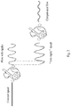
- Fig. 1 illustrates structures and flow ripple patterns of different types of hydraulic pumps. As shown, for the external gear pump, axial piston pump and vane pump, although the required flows are constant, the actual flows fluctuate with rotation of the pumps, which is caused by the mechanical structures of the pumps.
- the present invention provides a pump system as it is defined in claim 1.
- Advantages of the present invention comprise at least one of the following: effectively reducing noises and vibrations of the pump system, increasing the control precision, stability, repeatability and service life of the system; enhancing customer values; being a low-cost solution; not harming dynamics of the system; needing no additional components and extra space.
- Fig. 2 illustrates the basic idea of the present invention.
- the hydraulic pump system receives a constant rotation speed signal, but generates a liquid flow with ripples.
- the solution of the present invention injects an anti-ripple signal into the control system of the hydraulic pump such that ripples in the flow outputted by the hydraulic pump are notably cancelled.
- Fig. 3 schematically illustrates the principle of generating flow ripples by a piston pump.
- the instantaneous flow rate it generates is not constant but with significant variations. This is due to the mechanical characteristics of the valve plate structure of the piston pump.
- a significant backflow occurs when the piston passes the damping grooves, thus causing flow ripples.
- Such flow ripples in turn generate pressure ripples, which travels all along the hydraulic circuit.
- Flow ripples are more fundamental but not easily to be captured by sensors. In contrast, pressure sensors are common, and easy to be obtained and installed.
- q total represents the total flow rate
- q a represents the average flow rate
- q k represents the kinematic flow variations
- q b represents the flow ripples generated by the backflow
- ⁇ represents the rotation speed of the pump (i.e. the rotation speed of the electric motor)
- A represents the equivalent cross-sectional area of the piston cylinder
- p h represents the high pressure when backflow occurs
- p l represents the low pressure when backflow occurs.
- the kinematic flow variations represented by q k are flow ripples caused by the non-linear movement of the piston in the piston cylinder. As shown in the figure, the amplitude of such ripples is small, so the sum of q a and q k is approximately a constant value in proportion to the rotation speed of the pump. And the amplitude of the flow ripples (represented by q b ) generated by the backflow is large, which is a main source of noises and vibrations in the piston pump, and mainly depends on the pressure characteristics of the fluid in the pump, specifically, in proportion to the difference between the high pressure and the low pressure when the backflow occurs.
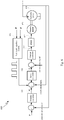
- Fig. 4 it illustrates a schematic diagram of a hydraulic pump system 400 according to an embodiment of the present invention.
- the hydraulic pump system 400 comprises an electric motor controller 410, an electric motor 420, and a hydraulic pump 430, wherein the electric motor controller 410 controls the operation of the electric motor 420 and the electric motor 420 drives the hydraulic pump 430.
- the hydraulic pump 430 may be any appropriate hydraulic pump applicable in any actual situation, such as a piston pump, external gear pump, vane pump, etc.
- the electric motor 420 may be any appropriate electric motor suitable to be driven by a VFD, such as an AD servo electric motor.
- the electric motor controller 410 may also be called an electric motor drive, and is a VFD in an embodiment of the present invention. As shown in the figure and known by those skilled in the art, the VFD comprises a digital signal processing (DSP) controller 411 and an Insulated Gate Bipolar Transistor (IGBT) drive circuit 412.
- DSP digital signal processing
- IGBT Insulated Gate Bipolar Transistor
- the DSP controller 411 generates a PWM signal based on a command of rotation speed, pressure or the like inputted by the user, and the PWM signal controls on and off of the transistors in the IGBT drive circuit 412 so as to drive the electric motor to rotate with an appropriate current and/or voltage.
- control system may be within the DSP controller 411 and implemented by software code in the DSP controller 411.
- software code has been hardwired into the DSP controller hardware, in which case, the control system will be implemented by hardware.
- the pressure controller 501 receives a combination of a fourth control signal (e.g. a target pressure value at the outlet of the hydraulic pump, set by the user) and a pressure feedback signal from a pressure sensor at the outlet of the hydraulic pump as input, and outputs a third control signal.
- the pressure controller 501 may be any appropriate existing (or newly developed) pressure controller, such as a PID (Proportion Integration Differentiation) controller.
- the current controller 503 receives a combination of the second control signal outputted by the speed controller 502, a current feedback signal from a current sensor at the input of the electric motor and a current anti-ripple signal from the anti-ripple injection module 504 as input, and outputs a first control signal.
- the first control signal drives the electric motor to rotate via a PWM drive circuit (i.e. IGBT drive circuit), and the electric motor in turn drives the hydraulic pump to operate.
- the current controller 502 may be any appropriate existing (or newly developed) current controller, such as, a PI (Proportion Integration) controller.
- the current at the input of the electric motor is in proportion to the torque of the electric motor, so that control of the current is equivalent to control of the torque, and the current controller may also be called a torque controller.
- the rotation angle signal ⁇ of the motor shaft may come from an angle sensor or position sensor installed on the electric motor; the rotation speed signal ⁇ of the electric motor may come from a speed sensor installed on the electric motor or may be obtained by computing the changing rate over time of the angle signal ⁇ ; and the outlet pressure signal p of the hydraulic pump may come from a pressure sensor installed at the output of the hydraulic pump.
- Fig. 6 it illustrates a schematic diagram of the control system according to another embodiment of the present invention.
- the control system comprises a pressure controller 501, a speed controller 502, a current controller 503, and an anti-ripple injection module 604.
- the control system differs from the control system shown by Fig. 5 in that the anti-ripple injection module 604 injects a speed anti-ripple signal into the speed loop instead of the current loop.
- the pressure controller 501 is the same as the pressure controller 501 shown in Fig. 5 , and is not described further in detail.
- the speed controller 502 receives a combination of a third control signal outputted by the pressure controller 501, a speed feedback signal from a speed sensor at the output of the electric motor and a speed anti-ripple signal from the anti-ripple injection module 604 as input, and outputs a second control signal.
- the current controller 503 receives a combination of the second control signal outputted by the speed controller 502 and a current feedback signal from a current sensor at the input of the electric motor as input, and outputs a first control signal.
- the first control signal drives the electric motor to rotate via the PWM drive circuit (i.e. IGBT drive circuit), which in turn drives the hydraulic pump to operate.
- the PWM drive circuit i.e. IGBT drive circuit
- the anti-ripple injection module 604 generates a speed anti-ripple signal based on a rotation angle signal ⁇ of the motor shaft, a rotation speed signal ⁇ of the electric motor, and an outlet pressure signal p of the hydraulic pump, and injects the speed anti-ripple signal into the speed loop of the control system, that is, the anti-ripple signal is combined with the second control signal and the current feedback signal at the input of the current controller 503 to be provided to the current controller 503.
- the core module of the present invention is the anti-ripple injection module 504, 604. All the other modules may be a conventional implementation of the "pressure closed-loop control" that has been widely used in industrial machines and other related applications.
- the structure of the control system illustrated in Figs. 5 and 6 and described above is only exemplary, rather than limitation to the present invention.
- the positional relation between the pressure controller 501 and the speed controller 502 may be contrary to that is illustrated and described; the control system may not include any or both of the pressure controller 501 and the speed controller 502; the control system may also include other controllers, other components or control loops, and so on.
- Choice between the two embodiments i.e. injecting the speed anti-ripple signal into the speed loop or injecting the current anti-ripple signal into the current loop
- the current control loop has a much higher bandwidth (up to 1KHz) than that of the speed control loop (about 100 Hz).
- the speed anti-ripple signal injection method may be adopted when the rotating speed is less than 300 rpm, and the current anti-ripple signal injection method may be adopted when the rotating speed is less than 3000 rpm.
- the function of the anti-ripple injection modules 504, 604 is to obtain the pressure signal from a pressure sensor and the angle signal from an angle sensor, and thereby, to compute an anti-ripple signal to modify the second or third control signal.
- the anti-ripple signal generated by the anti-ripple injection module 504, 604 is a periodic function of the rotation angle of the motor shaft instead of a periodic function of time.
- the waveform of the anti-ripple signal may be a conventional waveform, such as a square waveform, triangle waveform, and sinusoid waveform or the like.
- ⁇ 0 is directly related to the mechanical structure of the pump and only needs to be measured once and is fixed.
- a 0 is a parameter depending on the operation state (including the rotation speed of the electric motor and outlet pressure of the hydraulic pump) of the electric motor and the hydraulic pump.
- a method for determining the parameters is to conduct sufficient tests to build a lookup table and to determine the parameters of the periodic function using the lookup table. Specifically, during the tests, for each combination in a great amount of combinations of different measured values of the rotation speed ⁇ of the electric motor and the outlet pressure p of the hydraulic pump, different combinations of values of parameters A 0 and ⁇ 0 are designated, and anti-ripple signals with different combinations of parameter values are injected into the control path of the control system. And ripples in the outlet pressures of the hydraulic pump are measured to obtain a combination of parameter values that produce a minimum outlet pressure ripple.
- the lookup table can be built, which lists the mapping relations between different combinations of measured values of the rotation speed ⁇ of the electric motor and the output pressure p of the hydraulic pump and appropriate values of the parameters A 0 and ⁇ 0 .
- the anti-ripple injection modules 504, 604 may look up in the lookup table for the values of the corresponding parameters A 0 and ⁇ 0 based on the measured rotation speed ⁇ of the electric motor and the output pressure p of the hydraulic pump, and then produce an anti-ripple signal with the parameter values to be injected into the control path of the control system.
- this method may be called an off-line determination method.
- an adaptive tuning algorithm may also be used to determine the parameters of the periodic function.
- the adaptive tuning algorithm may be any known adaptive control method, such as, the Least Mean Square (LMS) method or the Recursive Least Square (RLS) method or the like.
- LMS Least Mean Square
- RLS Recursive Least Square
- the basic idea of such methods is to actively set different parameters to the system, measure output results of system with the different parameters, and identify system parameters based on the change pattern and distribution of the output results.
- the adaptive tuning algorithm may, for any specific combination of measured values of the rotation speed ⁇ of the electric motor and the output pressure p of the hydraulic pump, obtain appropriate values of parameters A 0 and ⁇ 0 by continuously setting and adjusting parameter values A 0 and ⁇ 0 and measuring ripples in the corresponding outlet pressures of the hydraulic pump.
- This method can identify the parameters of the periodic function in the actual production operation of the hydraulic pump, thus it is an on-line method.
- Such adaptive tuning algorithms are well known in the art, so are not further described in detail.
- a hydraulic pump system and a VFD-based hydraulic pump control system are described above by referring to the figures. It should be pointed out that the description above is only exemplary, not limitation to the present invention. In other embodiments of the present invention, the system may have more, less or different modules, and the including, connecting and functional relations among these modules may be different from that described.
- the present invention further provides a control method of a VFD-based hydraulic pump, the control method controlling an electric motor via a VFD, the electric motor driving the pump, the control method comprising: injecting an anti-ripple signal into a control path, the anti-ripple signal causing pressure ripples in the pump output to be at least partially cancelled.
- the control path comprises a current controller which receives a combination of a second control signal and a current feedback signal from a current sensor at the input of the electric motor and provides a first control signal to the electric motor.
- the anti-ripple signal is combined with the second control signal and the current feedback signal to be provided to the current controller.
- control path further comprises a speed controller which receives a combination of a third control signal and a speed feedback signal from a speed sensor at the output of the electric motor, and directly or indirectly provides the second control signal to the current controller, wherein, the anti-ripple signal is combined with the third control signal and the speed feedback signal to be provided to the speed controller.
- control path further comprises a pressure controller which receives a combination of a fourth control signal and a pressure feedback signal from a pressure sensor at the output of the pump, and directly or indirectly provides the second control signal to the current controller.
- the anti-ripple signal is a periodic function of the rotation angle of the motor shaft.
- parameters of the periodic function are adaptively determined from pressure measurements at the output of the pump and rotation speed measurements at the output of the electric motor.
- parameters of the periodic function are determined via a lookup table which maps multiple combinations of the pressure measurements and the rotation speed measurements to corresponding parameters of the periodic function.
- control method further comprises: building the look-up table in an off-line test method in which, for each of the multiple combinations of the pressure measurements and the rotation speed measurements, parameters of the periodic function are adaptively adjusted until pressure ripples in the pump output are at least partially cancelled, thus obtaining parameters of the periodic function corresponding to each of the multiple combinations of the pressure measurements and the rotation speed measurements.
- parameters of the periodic function are determined using an online adaptive algorithm in which, for each of the multiple combinations of the pressure measurements and the rotation speed measurements, parameters of the periodic function are adaptively adjusted until pressure ripples in the pump output are at least partially cancelled.
- the pump is a piston pump
- the control method and control system can be validated by building a test demo hydraulic pump system and running the control method and control system thereon according to embodiments of the present invention.
- the test demo hydraulic pump system may comprise a programmable VFD, an AC servo motor and a dual-displacement Eaton 420 industrial pump, wherein the maximum current of the VFD is 120A; the rated rotation speed of the electric motor is 1500 rpm; the rated torque is 108 Nm; the rated current is 53.3A; the inertia (+pump) is 0.079 kgm2; the pump max displacement is 49 cc.
- the anti-ripple signal injection is performed on the speed loop.
- the duty cycle is a pressure holding @ 154bar.
- the pump displacement during pressure holding is set to about 25cc.
- the motor rotation speed is observed to be around 125 rpm to supply the system leakage flow.
- the injected signal is chosen to be a sinusoid signal.
- the amplitude A 0 and phase ⁇ 0 are determined through a lookup table from sufficient tests.
- Fig. 7 illustrates a diagram of measured data from pressure sensors in a test demo hydraulic pump system.
- the upper part of the diagram shows a comparison between the pressure signal with anti-ripple signal injection of the present invention and the pressure signal without anti-ripple signal injection of the present invention.
- the anti-ripple signal injection of the present invention is able to reduce as much as 60% of pressure ripples.
- the lower part of the diagram is a spectrum analysis of the ripple signals. From the figure, it can be seen that the ripples comprise only a portion of the harmonics. The most significant harmonic (2nd harmonic) is completely cancelled by the anti-ripple signal injection of the present invention, which contributes to pressure ripple reduction.
Description
- This invention relates to a pump, particularly to a control system and method of a VFD-based pump, as well as a pump system.
- Flow ripples or pressure ripples (fluctuations) generated from the hydraulic pump are the source of system vibrations and noises in a hydraulic system. Pressure ripples are also disturbance to motion control that affects the precision and repeatability of the movement.
-
Fig. 1 illustrates structures and flow ripple patterns of different types of hydraulic pumps. As shown, for the external gear pump, axial piston pump and vane pump, although the required flows are constant, the actual flows fluctuate with rotation of the pumps, which is caused by the mechanical structures of the pumps. - Noises impact human hearing health; vibrations reduce the reliability of the entire system; and the reduced precision directly affects the product quality produced by the hydraulic machine. From every aspect, pressure ripples reduce values delivered to customers. Therefore, pressure ripple reduction has been a core issue that researchers in both academic and industry world have tried to solve.
- Most current methods for reduction of flow and pressure ripples are based on novel mechanical designs or additional ripple compensators such as silencers or accumulators. These methods in general suffer from trade-offs among the costs, energy efficiency and system dynamic responses. For example, the method modifying pump shaft design lowers the energy efficiency; adding a pre-compression chamber increases manufacturing and component costs and reduces the efficiency; adding an accumulator or silencer at the pump outlet increases component costs and space, and lowers pump dynamics.
- Thus, a solution for reducing noises and vibrations of a pump with higher efficiency and lower costs is needed in the art.
- In
US 2013/0002187 A1 there is disclosed a pump system as it is defined in the precharacterizing portion of claim 1. A further pump system is disclosed inUS 5 971 714 A . - The present invention provides a pump system as it is defined in claim 1.
- Advantages of the present invention comprise at least one of the following: effectively reducing noises and vibrations of the pump system, increasing the control precision, stability, repeatability and service life of the system; enhancing customer values; being a low-cost solution; not harming dynamics of the system; needing no additional components and extra space.
-
-
Fig. 1 illustrates the structures and flow ripple patterns of different types of hydraulic pumps; -
Fig. 2 illustrates the basic idea of the present invention; -
Fig. 3 illustrates the principle of generating flow ripples by a piston pump; -
Fig. 4 illustrates a schematic diagram of the hydraulic pump system according to an embodiment of the present invention; -
Fig. 5 illustrates a schematic diagram of the control system according to an embodiment of the present invention; -
Fig. 6 illustrates a schematic diagram of the control system according to another embodiment of the present invention; and -
Fig. 7 illustrates a diagram of measured data from a pressure sensor in a test demo hydraulic pump system. - The embodiments of the present invention are described below by referring to figures. Numerous details are described below so that those skilled in the art can comprehensively understand and realize the present invention. However, it is apparent for those skilled in the art that the realization of the present invention may not include some of the details. In addition, it should be understood that the present invention is not limited to the described specific embodiments. On the contrary, it is contemplated that the present invention can be realized using any combination of the features and elements described below, no matter whether they relate to different embodiments or not. Therefore, the following aspects, features, embodiments and advantages are only for explanation, and should not be taken as elements of or limitations to the claims, unless explicitly stated otherwise in the claims.
- In view that currently more and more hydraulic pumps are driven by VFDs to achieve flexible speed or torque control, the present invention proposes a solution of reducing noises and vibrations of a hydraulic pump by means of a control solution applied to the VFD, which does not need additional hardware costs.
Fig. 2 illustrates the basic idea of the present invention. As shown, the hydraulic pump system receives a constant rotation speed signal, but generates a liquid flow with ripples. The solution of the present invention injects an anti-ripple signal into the control system of the hydraulic pump such that ripples in the flow outputted by the hydraulic pump are notably cancelled. -
Fig. 3 schematically illustrates the principle of generating flow ripples by a piston pump. As shown, when the piston is rotating at a constant speed, the instantaneous flow rate it generates is not constant but with significant variations. This is due to the mechanical characteristics of the valve plate structure of the piston pump. As shown inFig. 3 , a significant backflow occurs when the piston passes the damping grooves, thus causing flow ripples. Such flow ripples in turn generate pressure ripples, which travels all along the hydraulic circuit. Flow ripples are more fundamental but not easily to be captured by sensors. In contrast, pressure sensors are common, and easy to be obtained and installed. - The instantaneous flow rate at the pump outlet can be expressed in the following equation:

- The kinematic flow variations represented by qk are flow ripples caused by the non-linear movement of the piston in the piston cylinder. As shown in the figure, the amplitude of such ripples is small, so the sum of qa and qk is approximately a constant value in proportion to the rotation speed of the pump. And the amplitude of the flow ripples (represented by qb) generated by the backflow is large, which is a main source of noises and vibrations in the piston pump, and mainly depends on the pressure characteristics of the fluid in the pump, specifically, in proportion to the difference between the high pressure and the low pressure when the backflow occurs. The basic idea of the present invention with respect to a piston pump can be simply summarized as: increasing the rotation speed of the electric motor when the backflow occurs, which is illustrated schematically in the following table.
When the rotation speed signal of the electric motor is After applying the control method of the present invention ω' 

qa + qk 

qb 

qtotal 

- As shown by the table, when the rotation speed signal of the electric motor is constant, the sum of qa and qk is basically constant, but the ripple amplitude of qb is large such that the ripple amplitude of qtotal is also large. After injecting an anti-ripple signal according to a method of the present invention, a ripple having about the same amplitude but opposite direction will be present in the rotation speed signal of the electric motor such that such ripples will also be present in the sum of qa and qk. Thus, when the sum of qa and qk is added with qb, the ripples in the two will be cancelled with each other such that the ripple amplitude of qtotal is remarkably reduced.
- Now referring to
Fig. 4 , it illustrates a schematic diagram of ahydraulic pump system 400 according to an embodiment of the present invention. As shown, thehydraulic pump system 400 comprises anelectric motor controller 410, anelectric motor 420, and ahydraulic pump 430, wherein theelectric motor controller 410 controls the operation of theelectric motor 420 and theelectric motor 420 drives thehydraulic pump 430. - The
hydraulic pump 430 may be any appropriate hydraulic pump applicable in any actual situation, such as a piston pump, external gear pump, vane pump, etc. Theelectric motor 420 may be any appropriate electric motor suitable to be driven by a VFD, such as an AD servo electric motor. Theelectric motor controller 410 may also be called an electric motor drive, and is a VFD in an embodiment of the present invention. As shown in the figure and known by those skilled in the art, the VFD comprises a digital signal processing (DSP)controller 411 and an Insulated Gate Bipolar Transistor (IGBT)drive circuit 412. TheDSP controller 411 generates a PWM signal based on a command of rotation speed, pressure or the like inputted by the user, and the PWM signal controls on and off of the transistors in theIGBT drive circuit 412 so as to drive the electric motor to rotate with an appropriate current and/or voltage. - The control system according to an embodiment of the present invention may be within the
DSP controller 411 and implemented by software code in theDSP controller 411. Of course, it may also be contemplated that the software code has been hardwired into the DSP controller hardware, in which case, the control system will be implemented by hardware. - Now referring to
Fig. 5 , it illustrates a schematic diagram of the control system according to an embodiment of the present invention. As shown, thecontrol system 500 comprises apressure controller 501, aspeed controller 502, acurrent controller 503, and ananti-ripple injection module 504. - The
pressure controller 501 receives a combination of a fourth control signal (e.g. a target pressure value at the outlet of the hydraulic pump, set by the user) and a pressure feedback signal from a pressure sensor at the outlet of the hydraulic pump as input, and outputs a third control signal. Thepressure controller 501 may be any appropriate existing (or newly developed) pressure controller, such as a PID (Proportion Integration Differentiation) controller. - The
speed controller 502 receives a combination of the third control signal outputted by thepressure controller 501 and a speed feedback signal from a speed sensor at the output of the electric motor as input, and outputs a second control signal. Thespeed controller 502 may be any appropriate existing (or newly developed) speed controller, such as, a PI (Proportion Integration) controller. - The
current controller 503 receives a combination of the second control signal outputted by thespeed controller 502, a current feedback signal from a current sensor at the input of the electric motor and a current anti-ripple signal from theanti-ripple injection module 504 as input, and outputs a first control signal. The first control signal drives the electric motor to rotate via a PWM drive circuit (i.e. IGBT drive circuit), and the electric motor in turn drives the hydraulic pump to operate. Thecurrent controller 502 may be any appropriate existing (or newly developed) current controller, such as, a PI (Proportion Integration) controller. The current at the input of the electric motor is in proportion to the torque of the electric motor, so that control of the current is equivalent to control of the torque, and the current controller may also be called a torque controller. - According to an embodiment of the present invention, the
anti-ripple injection module 504 generates the current anti-ripple signal based on a rotation angle signal θ of the motor shaft, a rotation speed signal ω of the electric motor, and an outlet pressure signal p of the hydraulic pump, and injects the current anti-ripple signal into the current loop of the control system, that is, the anti-ripple signal is combined with the second control signal and the current feedback signal at the input of thecurrent controller 503 to be provided to thecurrent controller 503. The rotation angle signal θ of the motor shaft may come from an angle sensor or position sensor installed on the electric motor; the rotation speed signal ω of the electric motor may come from a speed sensor installed on the electric motor or may be obtained by computing the changing rate over time of the angle signal θ; and the outlet pressure signal p of the hydraulic pump may come from a pressure sensor installed at the output of the hydraulic pump. - Now referring to
Fig. 6 , it illustrates a schematic diagram of the control system according to another embodiment of the present invention. As shown, the control system comprises apressure controller 501, aspeed controller 502, acurrent controller 503, and ananti-ripple injection module 604. The control system differs from the control system shown byFig. 5 in that theanti-ripple injection module 604 injects a speed anti-ripple signal into the speed loop instead of the current loop. - The
pressure controller 501 is the same as thepressure controller 501 shown inFig. 5 , and is not described further in detail. - The
speed controller 502 receives a combination of a third control signal outputted by thepressure controller 501, a speed feedback signal from a speed sensor at the output of the electric motor and a speed anti-ripple signal from theanti-ripple injection module 604 as input, and outputs a second control signal. - The
current controller 503 receives a combination of the second control signal outputted by thespeed controller 502 and a current feedback signal from a current sensor at the input of the electric motor as input, and outputs a first control signal. The first control signal drives the electric motor to rotate via the PWM drive circuit (i.e. IGBT drive circuit), which in turn drives the hydraulic pump to operate. - According to this embodiment of the present invention, the
anti-ripple injection module 604 generates a speed anti-ripple signal based on a rotation angle signal θ of the motor shaft, a rotation speed signal ω of the electric motor, and an outlet pressure signal p of the hydraulic pump, and injects the speed anti-ripple signal into the speed loop of the control system, that is, the anti-ripple signal is combined with the second control signal and the current feedback signal at the input of thecurrent controller 503 to be provided to thecurrent controller 503. - According to an embodiment of the present invention, the core module of the present invention is the
anti-ripple injection module Figs. 5 and6 and described above is only exemplary, rather than limitation to the present invention. For example, the positional relation between thepressure controller 501 and thespeed controller 502 may be contrary to that is illustrated and described; the control system may not include any or both of thepressure controller 501 and thespeed controller 502; the control system may also include other controllers, other components or control loops, and so on. - Choice between the two embodiments (i.e. injecting the speed anti-ripple signal into the speed loop or injecting the current anti-ripple signal into the current loop) of the present invention described above depends on the frequency of the outlet pressure (or flow) ripples of the hydraulic pump in the time domain. In general, the current control loop has a much higher bandwidth (up to 1KHz) than that of the speed control loop (about 100 Hz). As a rule of thumb, for a piston pump with 9 pistons, the speed anti-ripple signal injection method may be adopted when the rotating speed is less than 300 rpm, and the current anti-ripple signal injection method may be adopted when the rotating speed is less than 3000 rpm.
- As described above, the function of the
anti-ripple injection modules anti-ripple injection module 
- The parameters of the periodic function can be determined in various ways. Both theories and experimental results have shown that θ 0 is directly related to the mechanical structure of the pump and only needs to be measured once and is fixed. A0 is a parameter depending on the operation state (including the rotation speed of the electric motor and outlet pressure of the hydraulic pump) of the electric motor and the hydraulic pump.
- According to embodiments of the present invention, a method for determining the parameters is to conduct sufficient tests to build a lookup table and to determine the parameters of the periodic function using the lookup table. Specifically, during the tests, for each combination in a great amount of combinations of different measured values of the rotation speed ω of the electric motor and the outlet pressure p of the hydraulic pump, different combinations of values of parameters A0 and θ 0 are designated, and anti-ripple signals with different combinations of parameter values are injected into the control path of the control system. And ripples in the outlet pressures of the hydraulic pump are measured to obtain a combination of parameter values that produce a minimum outlet pressure ripple. In this way, the lookup table can be built, which lists the mapping relations between different combinations of measured values of the rotation speed ω of the electric motor and the output pressure p of the hydraulic pump and appropriate values of the parameters A0 and θ 0. Thus, during the operation of the hydraulic pump system, the
anti-ripple injection modules - According to some other embodiments of the present invention, an adaptive tuning algorithm may also be used to determine the parameters of the periodic function. The adaptive tuning algorithm may be any known adaptive control method, such as, the Least Mean Square (LMS) method or the Recursive Least Square (RLS) method or the like. The basic idea of such methods is to actively set different parameters to the system, measure output results of system with the different parameters, and identify system parameters based on the change pattern and distribution of the output results. In the embodiments of the present invention, the adaptive tuning algorithm may, for any specific combination of measured values of the rotation speed ω of the electric motor and the output pressure p of the hydraulic pump, obtain appropriate values of parameters A0 and θ 0 by continuously setting and adjusting parameter values A0 and θ 0 and measuring ripples in the corresponding outlet pressures of the hydraulic pump. This method can identify the parameters of the periodic function in the actual production operation of the hydraulic pump, thus it is an on-line method. Such adaptive tuning algorithms are well known in the art, so are not further described in detail.
- A hydraulic pump system and a VFD-based hydraulic pump control system according to embodiments of the present invention are described above by referring to the figures. It should be pointed out that the description above is only exemplary, not limitation to the present invention. In other embodiments of the present invention, the system may have more, less or different modules, and the including, connecting and functional relations among these modules may be different from that described.
- As may be known by those skilled in the art based on the description above, the present invention further provides a control method of a VFD-based hydraulic pump, the control method controlling an electric motor via a VFD, the electric motor driving the pump, the control method comprising: injecting an anti-ripple signal into a control path, the anti-ripple signal causing pressure ripples in the pump output to be at least partially cancelled.
- According to an embodiment of the present invention, the control path comprises a current controller which receives a combination of a second control signal and a current feedback signal from a current sensor at the input of the electric motor and provides a first control signal to the electric motor.
- According to an embodiment of the present invention, the anti-ripple signal is combined with the second control signal and the current feedback signal to be provided to the current controller.
- According to an embodiment of the present invention, the control path further comprises a speed controller which receives a combination of a third control signal and a speed feedback signal from a speed sensor at the output of the electric motor, and directly or indirectly provides the second control signal to the current controller, wherein, the anti-ripple signal is combined with the third control signal and the speed feedback signal to be provided to the speed controller.
- According to an embodiment of the present invention, the control path further comprises a pressure controller which receives a combination of a fourth control signal and a pressure feedback signal from a pressure sensor at the output of the pump, and directly or indirectly provides the second control signal to the current controller.
- According to an embodiment of the present invention, the anti-ripple signal is a periodic function of the rotation angle of the motor shaft.
- According to an embodiment of the present invention, parameters of the periodic function are adaptively determined from pressure measurements at the output of the pump and rotation speed measurements at the output of the electric motor.
- According to an embodiment of the present invention, parameters of the periodic function are determined via a lookup table which maps multiple combinations of the pressure measurements and the rotation speed measurements to corresponding parameters of the periodic function.
- According to an embodiment of the present invention, the control method further comprises: building the look-up table in an off-line test method in which, for each of the multiple combinations of the pressure measurements and the rotation speed measurements, parameters of the periodic function are adaptively adjusted until pressure ripples in the pump output are at least partially cancelled, thus obtaining parameters of the periodic function corresponding to each of the multiple combinations of the pressure measurements and the rotation speed measurements.
- According to an embodiment of the present invention, parameters of the periodic function are determined using an online adaptive algorithm in which, for each of the multiple combinations of the pressure measurements and the rotation speed measurements, parameters of the periodic function are adaptively adjusted until pressure ripples in the pump output are at least partially cancelled.
- According to an embodiment of the present invention, the pump is a piston pump, and the anti-ripple signal is represented as:

- The control method and control system can be validated by building a test demo hydraulic pump system and running the control method and control system thereon according to embodiments of the present invention. The test demo hydraulic pump system may comprise a programmable VFD, an AC servo motor and a dual-
displacement Eaton 420 industrial pump, wherein the maximum current of the VFD is 120A; the rated rotation speed of the electric motor is 1500 rpm; the rated torque is 108 Nm; the rated current is 53.3A; the inertia (+pump) is 0.079 kgm2; the pump max displacement is 49 cc. - The anti-ripple signal injection is performed on the speed loop. The duty cycle is a pressure holding @ 154bar. The pump displacement during pressure holding is set to about 25cc. The motor rotation speed is observed to be around 125 rpm to supply the system leakage flow. The injected signal is chosen to be a sinusoid signal. The amplitude A0 and phase θ 0 are determined through a lookup table from sufficient tests.
-
Fig. 7 illustrates a diagram of measured data from pressure sensors in a test demo hydraulic pump system. The upper part of the diagram shows a comparison between the pressure signal with anti-ripple signal injection of the present invention and the pressure signal without anti-ripple signal injection of the present invention. As can be seen from the figure, the anti-ripple signal injection of the present invention is able to reduce as much as 60% of pressure ripples. The lower part of the diagram is a spectrum analysis of the ripple signals. From the figure, it can be seen that the ripples comprise only a portion of the harmonics. The most significant harmonic (2nd harmonic) is completely cancelled by the anti-ripple signal injection of the present invention, which contributes to pressure ripple reduction. - Although exemplary embodiments of the present invention are described above, the present invention is not limited to this. Those skilled in the art may make various changes and modifications without departing from the scope of the present invention. For example, it is contemplated that the technical solution of the present invention may also be applicable to other fluid pumps than hydraulic pumps. The scope of the present invention is only defined by the claims.
Claims (8)
- A pump system, comprising:a VFD-based hydraulic pump (430),a VFD, andan electric motor (420) driving the pump, andwherein the VFD comprises a control system (500) for controlling the electric motor (420) via the VFD, the control system comprising:an anti-ripple injection module (504) for injecting an anti-ripple signal into a control path, the anti-ripple signal causing pressure ripples in the pump output to be at least partially cancelled;wherein the control system further comprises a current controller (503) configured to receive a combination of a second control signal and a current feedback signal from a current sensor at the input of the electric motor (420) and to provide a first control signal to the electric motor;characterized in that the anti-rippie injection module (504) is configured to combine the anti-ripple signal with the second control signal and the current feedback signal to be provided to the current controller (503).
- The pump system according to claim 1, further comprising a speed controller (502) configured to receive a combination of a third control signal and a speed feedback signal from a speed sensor at the output of the electric motor (420), and to directly or indirectly provide the second control signal to the current controller, wherein the anti-ripple injection module (504) is configured to combine the anti-ripple signal with the third control signal and the speed feedback signal to be provided to the speed controller (502).
- The pump system according to any of the preceding claims, further comprising a pressure controller (501) configured to receive a combination of a fourth control signal and a pressure feedback signal from a pressure sensor at the output of the pump (430), and to directly or indirectly provide the second control signal to the current controller (503).
- The pump system according to claim 1, wherein the anti-ripple signal is a periodic function of the rotation angle of the motor shaft.
- The pump system according to claim 4, configured to adaptively determine parameters of the periodic function from pressure measurements at the output of the pump (430) and rotation speed measurements at the output of the electric motor (420).
- The pump system according to claim 5, configured to determine parameters of the periodic function via a look-up table which maps multiple combinations of the pressure measurements and the rotation speed measurements to corresponding parameters of the periodic function.
- The pump system according to claim 5, configured to determine parameters of the periodic function using an online adaptive algorithm in which, for each of the multiple combinations of the pressure measurements and rotation speed measurements, parameters of the periodic function are adaptively adjusted until pressure ripples in the pump output are at least partially cancelled.
- The pump system according to any of claims 4 to 7, wherein the pump (430) is a piston pump, and the anti-ripple signal is represented as:

Applications Claiming Priority (2)
| Application Number | Priority Date | Filing Date | Title |
|---|---|---|---|
| CN201310265564.3A CN104251201B (en) | 2013-06-28 | 2013-06-28 | The control system of pump based on converter and method and pumping system |
| PCT/CN2014/080970 WO2014206339A1 (en) | 2013-06-28 | 2014-06-27 | Control system and method of a vfd-based pump and pump system |
Publications (3)
| Publication Number | Publication Date |
|---|---|
| EP3014123A1 EP3014123A1 (en) | 2016-05-04 |
| EP3014123A4 EP3014123A4 (en) | 2017-01-25 |
| EP3014123B1 true EP3014123B1 (en) | 2020-02-05 |
Family
ID=52141102
Family Applications (1)
| Application Number | Title | Priority Date | Filing Date |
|---|---|---|---|
| EP14818247.0A Active EP3014123B1 (en) | 2013-06-28 | 2014-06-27 | A pump system |
Country Status (4)
| Country | Link |
|---|---|
| US (1) | US10655621B2 (en) |
| EP (1) | EP3014123B1 (en) |
| CN (1) | CN104251201B (en) |
| WO (1) | WO2014206339A1 (en) |
Families Citing this family (10)
| Publication number | Priority date | Publication date | Assignee | Title |
|---|---|---|---|---|
| DE102015108923B3 (en) * | 2015-06-05 | 2016-06-16 | Nidec Gpm Gmbh | Electrically driven liquid displacement pump |
| DE102015108925B8 (en) * | 2015-06-05 | 2016-08-18 | Nidec Gpm Gmbh | Electrically driven liquid filter pump |
| ITUB20155957A1 (en) * | 2015-11-27 | 2017-05-27 | Gefran Spa | METHOD OF CONTROL OF AN ELECTRIC MOTOR OF A SERVO PUMP OF AN INDUSTRIAL MACHINERY TO MODIFY A HYDRAULIC PRESSURE APPLIED BY THE SERVO-PUMP TO A LOAD. |
| CN105508320B (en) * | 2016-02-24 | 2017-06-16 | 益阳新华美机电科技有限公司 | Two parallel pumps hydraulic pressure converter plant and rubber mixing machine drum driven system |
| DE102016106483B4 (en) * | 2016-04-08 | 2019-02-07 | Jenaer Antriebstechnik Gmbh | Method for compensation of cyclical disturbances during operation of a pump and control unit |
| CN107605716B (en) * | 2016-07-11 | 2019-07-16 | 西门子(中国)有限公司 | The soft pump control system of frequency converter controller and slush pump |
| WO2018207157A2 (en) * | 2017-05-11 | 2018-11-15 | Eaton Intelligent Power Limited | Pressure control in a dead-headed hydraulic system using pump motion control |
| DE102018217230A1 (en) * | 2018-10-09 | 2020-04-09 | Robert Bosch Gmbh | Method and device for controlling a fluid pump |
| EP3825553B1 (en) * | 2019-11-25 | 2024-01-10 | Grundfos Holding A/S | Method for controlling a water utility system using a user perception of noise |
| US20230021491A1 (en) * | 2021-07-23 | 2023-01-26 | Hamilton Sundstrand Corporation | Displacement pump pressure feedback control and method of control |
Citations (1)
| Publication number | Priority date | Publication date | Assignee | Title |
|---|---|---|---|---|
| US20130002187A1 (en) * | 2010-03-12 | 2013-01-03 | Franklin Electric Company, Inc. | Variable speed drive system |
Family Cites Families (15)
| Publication number | Priority date | Publication date | Assignee | Title |
|---|---|---|---|---|
| US4822250A (en) * | 1986-03-24 | 1989-04-18 | Hitachi, Ltd. | Apparatus for transferring small amount of fluid |
| JP2604362B2 (en) * | 1986-10-22 | 1997-04-30 | 株式会社日立製作所 | Low pulsation pump |
| JPH07286584A (en) * | 1994-04-19 | 1995-10-31 | Hitachi Ltd | Inverter-driven screw compressor |
| US5668457A (en) * | 1995-06-30 | 1997-09-16 | Martin Marietta Corporation | Variable-frequency AC induction motor controller |
| US5971714A (en) * | 1996-05-29 | 1999-10-26 | Graco Inc | Electronic CAM compensation of pressure change of servo controlled pumps |
| JPH10159743A (en) * | 1996-11-29 | 1998-06-16 | Tokimec Inc | Hydraulic control system |
| US6109878A (en) * | 1998-04-13 | 2000-08-29 | Micropump, Inc. | System and a method for velocity modulation for pulseless operation of a pump |
| US6018957A (en) * | 1998-12-07 | 2000-02-01 | Carrier Corporation | Method and apparatus for controlling beats and minimizing pulsation effects in multiple compressor installations |
| US8540493B2 (en) * | 2003-12-08 | 2013-09-24 | Sta-Rite Industries, Llc | Pump control system and method |
| DE102005025590A1 (en) * | 2005-06-03 | 2006-12-07 | Hydac Electronic Gmbh | Regulating device and method for operating a control device |
| RU2381384C1 (en) * | 2005-10-13 | 2010-02-10 | Пампвелл Солюшнз Лтд. | Method and system to control rod travel in system pumping fluid out of well |
| KR101243509B1 (en) * | 2005-12-02 | 2013-03-20 | 엔테그리스, 아이엔씨. | System and method for pressure compensation in a pump |
| CN201057139Y (en) * | 2007-06-22 | 2008-05-07 | 谭书涛 | Pressure controller of fluid pump |
| US10100827B2 (en) * | 2008-07-28 | 2018-10-16 | Eaton Intelligent Power Limited | Electronic control for a rotary fluid device |
| ATE552423T1 (en) * | 2010-02-12 | 2012-04-15 | Allweiler Ag | OPERATIONAL CONTROL DEVICE FOR A DISPLACEMENT PUMP, PUMP SYSTEM AND METHOD FOR OPERATING SAME |
-
2013
- 2013-06-28 CN CN201310265564.3A patent/CN104251201B/en active Active
-
2014
- 2014-06-27 EP EP14818247.0A patent/EP3014123B1/en active Active
- 2014-06-27 WO PCT/CN2014/080970 patent/WO2014206339A1/en active Application Filing
- 2014-06-27 US US14/899,992 patent/US10655621B2/en active Active
Patent Citations (1)
| Publication number | Priority date | Publication date | Assignee | Title |
|---|---|---|---|---|
| US20130002187A1 (en) * | 2010-03-12 | 2013-01-03 | Franklin Electric Company, Inc. | Variable speed drive system |
Also Published As
| Publication number | Publication date |
|---|---|
| CN104251201A (en) | 2014-12-31 |
| EP3014123A1 (en) | 2016-05-04 |
| EP3014123A4 (en) | 2017-01-25 |
| WO2014206339A1 (en) | 2014-12-31 |
| CN104251201B (en) | 2016-12-28 |
| US10655621B2 (en) | 2020-05-19 |
| US20180080443A1 (en) | 2018-03-22 |
Similar Documents
| Publication | Publication Date | Title |
|---|---|---|
| EP3014123B1 (en) | A pump system | |
| CN105515484B (en) | The suppressing method and device and compressor control system of the rotary vibration of compressor | |
| EP3014122B1 (en) | Anti-ripple injection method and pump system | |
| JP4425253B2 (en) | Hydraulic unit and motor speed control method in hydraulic unit | |
| CN106762653B (en) | Torque in compressor compensation method, device and compressor and its control method | |
| CN105757889B (en) | The compensated torque device and method of air conditioner and its compressor | |
| CN107013447B (en) | Driven compressor system and its control method, device | |
| CN106968931B (en) | Driven compressor system and its control method, device | |
| US20150316077A1 (en) | Method for operating a hydraulic device with pump and servomotor, and associated hydraulic device | |
| CN103187909A (en) | Motor control unit and electric pump unit | |
| JP5291325B2 (en) | Control device for motor connected to compressor | |
| JP2013527737A (en) | Rectifier and inverter based torsional mode damping system and method | |
| US20150198160A1 (en) | Method for optimizing the control of an electric drive | |
| MX2012011136A (en) | Sensorless torsional mode damping system and method. | |
| MX2012011247A (en) | Rectifier based torsional mode damping system and method. | |
| CN102714478B (en) | Anticipatory control system for electric motor and anticipatory control method for electric motor applied to cyclic loads | |
| KR101162954B1 (en) | Oscillation reductive method of compressor based on a frequency analysis with speed ripple and apparatus thereof | |
| Gencer | A new speed/position control technique for travelling wave ultrasonic motor under different load conditions | |
| JP2014034932A (en) | Motor control device and electric pump unit | |
| CN113794411B (en) | Multiple anti-interference control method of embedded permanent magnet synchronous motor for aviation plunger pump | |
| JP2016534688A (en) | System and method for controlling operation of an electric motor of a compressor | |
| Rossi et al. | Discrete multi-layer estimator implementation for sensorless control of elastic drive systems—An industrial case study | |
| CN114696710A (en) | Hydraulic pump system with output ripple compensation and related method | |
| CN102714477B (en) | Control system for electric motor applied to cyclic loads and control method for electric motor applied to cyclic loads | |
| JP2014031724A (en) | Motor control device and electric pump unit |
Legal Events
| Date | Code | Title | Description |
|---|---|---|---|
| PUAI | Public reference made under article 153(3) epc to a published international application that has entered the european phase |
Free format text: ORIGINAL CODE: 0009012 |
|
| 17P | Request for examination filed |
Effective date: 20151214 |
|
| AK | Designated contracting states |
Kind code of ref document: A1 Designated state(s): AL AT BE BG CH CY CZ DE DK EE ES FI FR GB GR HR HU IE IS IT LI LT LU LV MC MK MT NL NO PL PT RO RS SE SI SK SM TR |
|
| AX | Request for extension of the european patent |
Extension state: BA ME |
|
| DAX | Request for extension of the european patent (deleted) | ||
| REG | Reference to a national code |
Ref country code: DE Ref legal event code: R079 Ref document number: 602014060652 Country of ref document: DE Free format text: PREVIOUS MAIN CLASS: F04B0049060000 Ipc: F04B0011000000 |
|
| A4 | Supplementary search report drawn up and despatched |
Effective date: 20161223 |
|
| RIC1 | Information provided on ipc code assigned before grant |
Ipc: F04B 11/00 20060101AFI20161219BHEP Ipc: F04B 49/08 20060101ALI20161219BHEP Ipc: F04B 49/06 20060101ALI20161219BHEP Ipc: F04B 17/03 20060101ALI20161219BHEP |
|
| STAA | Information on the status of an ep patent application or granted ep patent |
Free format text: STATUS: EXAMINATION IS IN PROGRESS |
|
| 17Q | First examination report despatched |
Effective date: 20171208 |
|
| GRAP | Despatch of communication of intention to grant a patent |
Free format text: ORIGINAL CODE: EPIDOSNIGR1 |
|
| STAA | Information on the status of an ep patent application or granted ep patent |
Free format text: STATUS: GRANT OF PATENT IS INTENDED |
|
| INTG | Intention to grant announced |
Effective date: 20190912 |
|
| GRAS | Grant fee paid |
Free format text: ORIGINAL CODE: EPIDOSNIGR3 |
|
| GRAA | (expected) grant |
Free format text: ORIGINAL CODE: 0009210 |
|
| STAA | Information on the status of an ep patent application or granted ep patent |
Free format text: STATUS: THE PATENT HAS BEEN GRANTED |
|
| AK | Designated contracting states |
Kind code of ref document: B1 Designated state(s): AL AT BE BG CH CY CZ DE DK EE ES FI FR GB GR HR HU IE IS IT LI LT LU LV MC MK MT NL NO PL PT RO RS SE SI SK SM TR |
|
| REG | Reference to a national code |
Ref country code: GB Ref legal event code: FG4D |
|
| REG | Reference to a national code |
Ref country code: AT Ref legal event code: REF Ref document number: 1230093 Country of ref document: AT Kind code of ref document: T Effective date: 20200215 |
|
| REG | Reference to a national code |
Ref country code: DE Ref legal event code: R096 Ref document number: 602014060652 Country of ref document: DE |
|
| REG | Reference to a national code |
Ref country code: IE Ref legal event code: FG4D |
|
| REG | Reference to a national code |
Ref country code: CH Ref legal event code: EP |
|
| REG | Reference to a national code |
Ref country code: NL Ref legal event code: MP Effective date: 20200205 |
|
| PG25 | Lapsed in a contracting state [announced via postgrant information from national office to epo] |
Ref country code: RS Free format text: LAPSE BECAUSE OF FAILURE TO SUBMIT A TRANSLATION OF THE DESCRIPTION OR TO PAY THE FEE WITHIN THE PRESCRIBED TIME-LIMIT Effective date: 20200205 Ref country code: FI Free format text: LAPSE BECAUSE OF FAILURE TO SUBMIT A TRANSLATION OF THE DESCRIPTION OR TO PAY THE FEE WITHIN THE PRESCRIBED TIME-LIMIT Effective date: 20200205 Ref country code: NO Free format text: LAPSE BECAUSE OF FAILURE TO SUBMIT A TRANSLATION OF THE DESCRIPTION OR TO PAY THE FEE WITHIN THE PRESCRIBED TIME-LIMIT Effective date: 20200505 Ref country code: PT Free format text: LAPSE BECAUSE OF FAILURE TO SUBMIT A TRANSLATION OF THE DESCRIPTION OR TO PAY THE FEE WITHIN THE PRESCRIBED TIME-LIMIT Effective date: 20200628 |
|
| REG | Reference to a national code |
Ref country code: LT Ref legal event code: MG4D |
|
| PG25 | Lapsed in a contracting state [announced via postgrant information from national office to epo] |
Ref country code: SE Free format text: LAPSE BECAUSE OF FAILURE TO SUBMIT A TRANSLATION OF THE DESCRIPTION OR TO PAY THE FEE WITHIN THE PRESCRIBED TIME-LIMIT Effective date: 20200205 Ref country code: LV Free format text: LAPSE BECAUSE OF FAILURE TO SUBMIT A TRANSLATION OF THE DESCRIPTION OR TO PAY THE FEE WITHIN THE PRESCRIBED TIME-LIMIT Effective date: 20200205 Ref country code: HR Free format text: LAPSE BECAUSE OF FAILURE TO SUBMIT A TRANSLATION OF THE DESCRIPTION OR TO PAY THE FEE WITHIN THE PRESCRIBED TIME-LIMIT Effective date: 20200205 Ref country code: GR Free format text: LAPSE BECAUSE OF FAILURE TO SUBMIT A TRANSLATION OF THE DESCRIPTION OR TO PAY THE FEE WITHIN THE PRESCRIBED TIME-LIMIT Effective date: 20200506 Ref country code: IS Free format text: LAPSE BECAUSE OF FAILURE TO SUBMIT A TRANSLATION OF THE DESCRIPTION OR TO PAY THE FEE WITHIN THE PRESCRIBED TIME-LIMIT Effective date: 20200605 Ref country code: BG Free format text: LAPSE BECAUSE OF FAILURE TO SUBMIT A TRANSLATION OF THE DESCRIPTION OR TO PAY THE FEE WITHIN THE PRESCRIBED TIME-LIMIT Effective date: 20200505 |
|
| PG25 | Lapsed in a contracting state [announced via postgrant information from national office to epo] |
Ref country code: NL Free format text: LAPSE BECAUSE OF FAILURE TO SUBMIT A TRANSLATION OF THE DESCRIPTION OR TO PAY THE FEE WITHIN THE PRESCRIBED TIME-LIMIT Effective date: 20200205 |
|
| PG25 | Lapsed in a contracting state [announced via postgrant information from national office to epo] |
Ref country code: RO Free format text: LAPSE BECAUSE OF FAILURE TO SUBMIT A TRANSLATION OF THE DESCRIPTION OR TO PAY THE FEE WITHIN THE PRESCRIBED TIME-LIMIT Effective date: 20200205 Ref country code: SK Free format text: LAPSE BECAUSE OF FAILURE TO SUBMIT A TRANSLATION OF THE DESCRIPTION OR TO PAY THE FEE WITHIN THE PRESCRIBED TIME-LIMIT Effective date: 20200205 Ref country code: CZ Free format text: LAPSE BECAUSE OF FAILURE TO SUBMIT A TRANSLATION OF THE DESCRIPTION OR TO PAY THE FEE WITHIN THE PRESCRIBED TIME-LIMIT Effective date: 20200205 Ref country code: DK Free format text: LAPSE BECAUSE OF FAILURE TO SUBMIT A TRANSLATION OF THE DESCRIPTION OR TO PAY THE FEE WITHIN THE PRESCRIBED TIME-LIMIT Effective date: 20200205 Ref country code: ES Free format text: LAPSE BECAUSE OF FAILURE TO SUBMIT A TRANSLATION OF THE DESCRIPTION OR TO PAY THE FEE WITHIN THE PRESCRIBED TIME-LIMIT Effective date: 20200205 Ref country code: LT Free format text: LAPSE BECAUSE OF FAILURE TO SUBMIT A TRANSLATION OF THE DESCRIPTION OR TO PAY THE FEE WITHIN THE PRESCRIBED TIME-LIMIT Effective date: 20200205 Ref country code: SM Free format text: LAPSE BECAUSE OF FAILURE TO SUBMIT A TRANSLATION OF THE DESCRIPTION OR TO PAY THE FEE WITHIN THE PRESCRIBED TIME-LIMIT Effective date: 20200205 Ref country code: EE Free format text: LAPSE BECAUSE OF FAILURE TO SUBMIT A TRANSLATION OF THE DESCRIPTION OR TO PAY THE FEE WITHIN THE PRESCRIBED TIME-LIMIT Effective date: 20200205 |
|
| RAP2 | Party data changed (patent owner data changed or rights of a patent transferred) |
Owner name: EATON INTELLIGENT POWER LIMITED |
|
| REG | Reference to a national code |
Ref country code: DE Ref legal event code: R097 Ref document number: 602014060652 Country of ref document: DE |
|
| REG | Reference to a national code |
Ref country code: AT Ref legal event code: MK05 Ref document number: 1230093 Country of ref document: AT Kind code of ref document: T Effective date: 20200205 |
|
| PLBE | No opposition filed within time limit |
Free format text: ORIGINAL CODE: 0009261 |
|
| STAA | Information on the status of an ep patent application or granted ep patent |
Free format text: STATUS: NO OPPOSITION FILED WITHIN TIME LIMIT |
|
| 26N | No opposition filed |
Effective date: 20201106 |
|
| PG25 | Lapsed in a contracting state [announced via postgrant information from national office to epo] |
Ref country code: AT Free format text: LAPSE BECAUSE OF FAILURE TO SUBMIT A TRANSLATION OF THE DESCRIPTION OR TO PAY THE FEE WITHIN THE PRESCRIBED TIME-LIMIT Effective date: 20200205 Ref country code: MC Free format text: LAPSE BECAUSE OF FAILURE TO SUBMIT A TRANSLATION OF THE DESCRIPTION OR TO PAY THE FEE WITHIN THE PRESCRIBED TIME-LIMIT Effective date: 20200205 Ref country code: IT Free format text: LAPSE BECAUSE OF FAILURE TO SUBMIT A TRANSLATION OF THE DESCRIPTION OR TO PAY THE FEE WITHIN THE PRESCRIBED TIME-LIMIT Effective date: 20200205 |
|
| REG | Reference to a national code |
Ref country code: CH Ref legal event code: PL |
|
| PG25 | Lapsed in a contracting state [announced via postgrant information from national office to epo] |
Ref country code: SI Free format text: LAPSE BECAUSE OF FAILURE TO SUBMIT A TRANSLATION OF THE DESCRIPTION OR TO PAY THE FEE WITHIN THE PRESCRIBED TIME-LIMIT Effective date: 20200205 Ref country code: PL Free format text: LAPSE BECAUSE OF FAILURE TO SUBMIT A TRANSLATION OF THE DESCRIPTION OR TO PAY THE FEE WITHIN THE PRESCRIBED TIME-LIMIT Effective date: 20200205 |
|
| GBPC | Gb: european patent ceased through non-payment of renewal fee |
Effective date: 20200627 |
|
| PG25 | Lapsed in a contracting state [announced via postgrant information from national office to epo] |
Ref country code: LU Free format text: LAPSE BECAUSE OF NON-PAYMENT OF DUE FEES Effective date: 20200627 |
|
| REG | Reference to a national code |
Ref country code: BE Ref legal event code: MM Effective date: 20200630 |
|
| PG25 | Lapsed in a contracting state [announced via postgrant information from national office to epo] |
Ref country code: FR Free format text: LAPSE BECAUSE OF NON-PAYMENT OF DUE FEES Effective date: 20200630 Ref country code: LI Free format text: LAPSE BECAUSE OF NON-PAYMENT OF DUE FEES Effective date: 20200630 Ref country code: CH Free format text: LAPSE BECAUSE OF NON-PAYMENT OF DUE FEES Effective date: 20200630 Ref country code: IE Free format text: LAPSE BECAUSE OF NON-PAYMENT OF DUE FEES Effective date: 20200627 Ref country code: GB Free format text: LAPSE BECAUSE OF NON-PAYMENT OF DUE FEES Effective date: 20200627 |
|
| PG25 | Lapsed in a contracting state [announced via postgrant information from national office to epo] |
Ref country code: BE Free format text: LAPSE BECAUSE OF NON-PAYMENT OF DUE FEES Effective date: 20200630 |
|
| PG25 | Lapsed in a contracting state [announced via postgrant information from national office to epo] |
Ref country code: TR Free format text: LAPSE BECAUSE OF FAILURE TO SUBMIT A TRANSLATION OF THE DESCRIPTION OR TO PAY THE FEE WITHIN THE PRESCRIBED TIME-LIMIT Effective date: 20200205 Ref country code: MT Free format text: LAPSE BECAUSE OF FAILURE TO SUBMIT A TRANSLATION OF THE DESCRIPTION OR TO PAY THE FEE WITHIN THE PRESCRIBED TIME-LIMIT Effective date: 20200205 Ref country code: CY Free format text: LAPSE BECAUSE OF FAILURE TO SUBMIT A TRANSLATION OF THE DESCRIPTION OR TO PAY THE FEE WITHIN THE PRESCRIBED TIME-LIMIT Effective date: 20200205 |
|
| REG | Reference to a national code |
Ref country code: DE Ref legal event code: R081 Ref document number: 602014060652 Country of ref document: DE Owner name: DANFOSS POWER SOLUTIONS II TECHNOLOGY A/S, DK Free format text: FORMER OWNER: EATON CORPORATION, CLEVELAND, OHIO, US |
|
| PG25 | Lapsed in a contracting state [announced via postgrant information from national office to epo] |
Ref country code: MK Free format text: LAPSE BECAUSE OF FAILURE TO SUBMIT A TRANSLATION OF THE DESCRIPTION OR TO PAY THE FEE WITHIN THE PRESCRIBED TIME-LIMIT Effective date: 20200205 Ref country code: AL Free format text: LAPSE BECAUSE OF FAILURE TO SUBMIT A TRANSLATION OF THE DESCRIPTION OR TO PAY THE FEE WITHIN THE PRESCRIBED TIME-LIMIT Effective date: 20200205 |
|
| P01 | Opt-out of the competence of the unified patent court (upc) registered |
Effective date: 20230617 |
|
| PGFP | Annual fee paid to national office [announced via postgrant information from national office to epo] |
Ref country code: DE Payment date: 20230502 Year of fee payment: 10 |