EP3014026B1 - System and methods for with a first and a second hand operated control, controlling motion on a work tool for a construction machine - Google Patents
System and methods for with a first and a second hand operated control, controlling motion on a work tool for a construction machine Download PDFInfo
- Publication number
- EP3014026B1 EP3014026B1 EP14818353.6A EP14818353A EP3014026B1 EP 3014026 B1 EP3014026 B1 EP 3014026B1 EP 14818353 A EP14818353 A EP 14818353A EP 3014026 B1 EP3014026 B1 EP 3014026B1
- Authority
- EP
- European Patent Office
- Prior art keywords
- link arm
- control
- control means
- work tool
- outer link
- Prior art date
- Legal status (The legal status is an assumption and is not a legal conclusion. Google has not performed a legal analysis and makes no representation as to the accuracy of the status listed.)
- Active
Links
Images


Classifications
-
- E—FIXED CONSTRUCTIONS
- E02—HYDRAULIC ENGINEERING; FOUNDATIONS; SOIL SHIFTING
- E02F—DREDGING; SOIL-SHIFTING
- E02F3/00—Dredgers; Soil-shifting machines
- E02F3/04—Dredgers; Soil-shifting machines mechanically-driven
- E02F3/28—Dredgers; Soil-shifting machines mechanically-driven with digging tools mounted on a dipper- or bucket-arm, i.e. there is either one arm or a pair of arms, e.g. dippers, buckets
- E02F3/36—Component parts
- E02F3/42—Drives for dippers, buckets, dipper-arms or bucket-arms
- E02F3/43—Control of dipper or bucket position; Control of sequence of drive operations
-
- E—FIXED CONSTRUCTIONS
- E02—HYDRAULIC ENGINEERING; FOUNDATIONS; SOIL SHIFTING
- E02F—DREDGING; SOIL-SHIFTING
- E02F3/00—Dredgers; Soil-shifting machines
- E02F3/04—Dredgers; Soil-shifting machines mechanically-driven
- E02F3/28—Dredgers; Soil-shifting machines mechanically-driven with digging tools mounted on a dipper- or bucket-arm, i.e. there is either one arm or a pair of arms, e.g. dippers, buckets
- E02F3/30—Dredgers; Soil-shifting machines mechanically-driven with digging tools mounted on a dipper- or bucket-arm, i.e. there is either one arm or a pair of arms, e.g. dippers, buckets with a dipper-arm pivoted on a cantilever beam, i.e. boom
- E02F3/32—Dredgers; Soil-shifting machines mechanically-driven with digging tools mounted on a dipper- or bucket-arm, i.e. there is either one arm or a pair of arms, e.g. dippers, buckets with a dipper-arm pivoted on a cantilever beam, i.e. boom working downwardly and towards the machine, e.g. with backhoes
-
- E—FIXED CONSTRUCTIONS
- E02—HYDRAULIC ENGINEERING; FOUNDATIONS; SOIL SHIFTING
- E02F—DREDGING; SOIL-SHIFTING
- E02F3/00—Dredgers; Soil-shifting machines
- E02F3/04—Dredgers; Soil-shifting machines mechanically-driven
- E02F3/28—Dredgers; Soil-shifting machines mechanically-driven with digging tools mounted on a dipper- or bucket-arm, i.e. there is either one arm or a pair of arms, e.g. dippers, buckets
- E02F3/36—Component parts
- E02F3/3604—Devices to connect tools to arms, booms or the like
- E02F3/3677—Devices to connect tools to arms, booms or the like allowing movement, e.g. rotation or translation, of the tool around or along another axis as the movement implied by the boom or arms, e.g. for tilting buckets
-
- E—FIXED CONSTRUCTIONS
- E02—HYDRAULIC ENGINEERING; FOUNDATIONS; SOIL SHIFTING
- E02F—DREDGING; SOIL-SHIFTING
- E02F3/00—Dredgers; Soil-shifting machines
- E02F3/04—Dredgers; Soil-shifting machines mechanically-driven
- E02F3/28—Dredgers; Soil-shifting machines mechanically-driven with digging tools mounted on a dipper- or bucket-arm, i.e. there is either one arm or a pair of arms, e.g. dippers, buckets
- E02F3/36—Component parts
- E02F3/3604—Devices to connect tools to arms, booms or the like
- E02F3/3677—Devices to connect tools to arms, booms or the like allowing movement, e.g. rotation or translation, of the tool around or along another axis as the movement implied by the boom or arms, e.g. for tilting buckets
- E02F3/3681—Rotators
-
- E—FIXED CONSTRUCTIONS
- E02—HYDRAULIC ENGINEERING; FOUNDATIONS; SOIL SHIFTING
- E02F—DREDGING; SOIL-SHIFTING
- E02F3/00—Dredgers; Soil-shifting machines
- E02F3/04—Dredgers; Soil-shifting machines mechanically-driven
- E02F3/28—Dredgers; Soil-shifting machines mechanically-driven with digging tools mounted on a dipper- or bucket-arm, i.e. there is either one arm or a pair of arms, e.g. dippers, buckets
- E02F3/36—Component parts
- E02F3/42—Drives for dippers, buckets, dipper-arms or bucket-arms
- E02F3/43—Control of dipper or bucket position; Control of sequence of drive operations
- E02F3/435—Control of dipper or bucket position; Control of sequence of drive operations for dipper-arms, backhoes or the like
-
- E—FIXED CONSTRUCTIONS
- E02—HYDRAULIC ENGINEERING; FOUNDATIONS; SOIL SHIFTING
- E02F—DREDGING; SOIL-SHIFTING
- E02F3/00—Dredgers; Soil-shifting machines
- E02F3/04—Dredgers; Soil-shifting machines mechanically-driven
- E02F3/28—Dredgers; Soil-shifting machines mechanically-driven with digging tools mounted on a dipper- or bucket-arm, i.e. there is either one arm or a pair of arms, e.g. dippers, buckets
- E02F3/36—Component parts
- E02F3/42—Drives for dippers, buckets, dipper-arms or bucket-arms
- E02F3/43—Control of dipper or bucket position; Control of sequence of drive operations
- E02F3/435—Control of dipper or bucket position; Control of sequence of drive operations for dipper-arms, backhoes or the like
- E02F3/437—Control of dipper or bucket position; Control of sequence of drive operations for dipper-arms, backhoes or the like providing automatic sequences of movements, e.g. linear excavation, keeping dipper angle constant
-
- E—FIXED CONSTRUCTIONS
- E02—HYDRAULIC ENGINEERING; FOUNDATIONS; SOIL SHIFTING
- E02F—DREDGING; SOIL-SHIFTING
- E02F9/00—Component parts of dredgers or soil-shifting machines, not restricted to one of the kinds covered by groups E02F3/00 - E02F7/00
- E02F9/20—Drives; Control devices
- E02F9/2004—Control mechanisms, e.g. control levers
-
- E—FIXED CONSTRUCTIONS
- E02—HYDRAULIC ENGINEERING; FOUNDATIONS; SOIL SHIFTING
- E02F—DREDGING; SOIL-SHIFTING
- E02F9/00—Component parts of dredgers or soil-shifting machines, not restricted to one of the kinds covered by groups E02F3/00 - E02F7/00
- E02F9/26—Indicating devices
- E02F9/264—Sensors and their calibration for indicating the position of the work tool
- E02F9/265—Sensors and their calibration for indicating the position of the work tool with follow-up actions (e.g. control signals sent to actuate the work tool)
Definitions
- the present invention relates to a system and a method for, with a first and a second hand operated control means, controlling movement on a work tool for a construction machine.
- the digging performed with a construction machine is performed with an excavation unit made from two fixed link arms, boom and shaft respectively, as well as a work tool in the form of e.g. a bucket.
- excavation units were maneuvered with steel wires and winches that would pull up the bucket, so called [bucket wheels].
- Crane tip controlling means that the tip of the crane is controlled by a single lever or other control. When the lever is moved forward, the tip of the crane moves in a rectilinear movement forward in the horizontal plane. If the control is moved to the left, the tip of the crane moves to the left, etc. A new control system then controls which valves that need to be activated in order to achieve the desired movement.
- a forest machine works in a completely different way than a construction machine.
- a harvesting unit which is completely free hanging from the tip of the crane.
- the freely hanging unit enables the head to follow and intercept a falling tree without any major forces other than tractor forces need to be absorbed by the lift arm. Without a free hanging unit, the crane risks being subjected to such large torque caused by the falling tree that the machine may break.
- the work tool In a construction machine, such as an excavator or a backhoe loader, the work tool must be turned with force in order to perform digging and excavation work.
- the work tool is fixed at the outer tip of the digging arm via an attachment device that enables both controlled rotation as well as tilting of the tool.
- a suitable such attachment device is a tiltrotator, which may be likened to the wrist of the excavator arm.
- An object of the present invention is therefore to provide a system and a method for more intuitive control of both the digging arm of a construction machine and the movement of a work tool in an integrated way.
- Another object is the provided a system and a method that makes it possible to adjust the velocity in the movement based on the desired task.
- the invention thus relates to a system for, with a first and a second hand operated control means, controlling movement on a work tool for a construction machine.
- the construction machine comprises a lower carriage, a top, a digging arm and a work tool.
- the digging arm comprises an inner link arm with a first and a second inner link arm end and an outer link arm with a first and a second outer link arm end.
- One joint connects the top with the first inner link arm end, one joint connects the second inner link arm end with the first outer link arm end and one joint connects the second outer link arm end with the work tool.
- the work tool is secured in the second outer link arm end via an attachment device that enables controlled rotation and controlled tilting of the work tool in relation to the outer link arm.
- the system is characterized in that the first hand operated control means is intended to control the position of the second outer link arm end and the second hand operated control means is intended to control the function of the tool.
- actuators are provided to, via control devices, control the relative movement between the attachment device and the outer link arm, the outer link arm and the inner link arm, as well as between the inner link arm and the top.
- the actuators that are provided may for example be single or double acting hydraulic cylinders, linear motors, screw lines or other devices that may create a relative movement between two parts connected with a joint. If hydraulic cylinders and hydraulic fluid is used, the control devices may be for example hydraulic valves. It is also possible to, as control devices, use electrical servos or other devices in order to, with power supply or otherwise, control the actuators.
- the system comprises a control system which converts the movements of the first and the second control means to signals that activate, deactivate and control the control devices that control the movements of the first and the second link arm, as well as the control devices provided in the attachment device that control the movement of the work tool.
- control system is arranged to control the velocity of the relative movement between the different moving parts, by via the control devices controlling at least one of power supply, pressure or flow in the different actuators and to the attachment device.
- the attachment device is a tiltrotator and comprises a rotor member intended to control the rotation of the work tool about a first attachment device axis as well as tilting device intended to control the tilt of the work tool about a second attachment device axis substantially perpendicular to the first attachment axis.
- At least one sensor is provided in the attachment device which measures the relative position between the separate parts of the attachment device and/or the force acting on the control devices that are provided connected with the attachment device.
- the force acting on the control devices is created by, for example, an increased hydraulic pressure or an increased resistance in the movement between the parts.
- the first and the second control means are possible to tilt in a movement parallel with at least a first and a second control means axis which are substantially perpendicular to each other, and rotate about a third control means axis that is substantially perpendicular to the first and the second control means axis.
- the first and the second control is possible to adjust in height along the vertical control means axis.
- a movement on the first control means is intended to control a movement for the second outer link arm end and where a movement on the second control means is intended to control a movement or a function of the tool.
- the first and the second control means is a touch screen.
- the invention also relates to a method for, with a first and a second hand operated control means, controlling a movement on a work tool of a construction machine, wherein the construction machine comprises a bottom carriage, a top, a digging arm and a work tool.
- the digging arm comprises an inner link arm with a first and a second inner link arm end and an outer link arm with a first and a second outer link arm end.
- One joint connects the top with the first inner link arm end, one joint connects the second inner link arm end with the first outer link arm end and one joint connects the second outer link arm end with the work tool.
- the work tool is attached in the second outer link arm end via an attachment device that enables controlled rotation and controlled tilting of the work tool relative to the outer link arm.
- the method is characterized in that it comprises the steps of: with the first hand operated control means control the position of the outer end of the outer link arm and with the second hand operated control means control the function of the tool.
- the method also comprises the step of, with a control system, converting the movements of the first and the second control means into signals that activate, deactivate and control control devices which control the movements of the first and second link arm and the work tool.
- the invention also relates to a computer program product stored in a computer readable medium, which when executed on a computer performs the steps according to the above method.
- the construction machine 1 comprises preferably a bottom carriage 2 with a driving belt 2a, a top 3 as well as a digging arm 4 and a work tool 5.
- the driving belts 2a are of course replaceable with wheels if desired.
- the digging arm 4 is made up of a at least one inner 4a and one outer link arm 4b, boom and shaft respectively, where the digging arm is made up of an inner link arm 4a with a first and a second inner link arm end 4a1, 4a2 and an outer link arm 4b with a first and a second outer link arm end 4b1, 4b2.
- One joint J1 connects the top 3 with the first inner link arm end 4a1 and one joint J2 connects the second inner link arm end 4a2 with the first outer link arm end 4b1.
- an attachment device 6 for the work tool 5 is attached via an additional joint J4 that enables a rotation about a third substantially horizontal machine axis MA3 that extends through the joint J3.
- the attachment device 6 enables controlled rotation and controlled tilting of the tool 5.
- All joints J1, J2 are operated by hydraulics and enable a rotation about first, second and third substantially horizontal machine axes MA1, MA2, MA3 which extend through the joints J1, J2, J3.
- At the respective joint J1, J2, J3 there is arranged at least one actuator HC1, HC2, HC3 which is controlled by control devices V1, V2, V3.
- the actuators are hydraulic cylinders and the control devices are hydraulic valves.
- the control devices V1, V2, V3 may then be provided in the main block in the machine, and be connected to the hydraulic cylinders via hoses. It is also possible to mount the control devices V1, V2, V3 directly at each joint.
- Each control device V1, V2, V3 controls a certain actuator HC1, HC2, HC3 which in turn controls the movement in a certain direction J1, J2, J3 of the excavator 1.
- the above mentioned attachment device 6 may be a tiltrotator, which is shown further in figure 2b .
- the tiltrotator comprises a rotor part 6a which makes it possible to, by force, rotate the tool 360 degrees in relation to the outer link arm 4b around a first attachment device axis IAA1. The rotation occurs with the help of an actuator that is further controlled by a control device V4 which is arranged in the rotor member 6a.
- the tiltrotator also comprises a tilting device 6b which makes it possible to angle the tool in relation to a second control means axis IAA2 substantially perpendicular to the first control means axis IAA1.
- the second tilting device 6b may be another rotor member arranged substantially perpendicular to the first rotor member or one or multiple hydraulic cylinders or other actuators, these also being controlled by control devices V5.
- the attachment device 6 there is also arranged one or multiple sensors S1, S2, .. Sn which are arranged to sense for example the relative position between the separate parts of the attachment device and the force acting on or the hydraulic pressure in the control devices V4, V5.
- the sensors may thus sense if and how much the tool is angled.
- the force that acts on the tool may be read by measuring increased hydraulic pressure or resistance to movement.
- hydraulic cylinders are used as actuators, it is for example possible to strangle the supply of hydraulic fluid to the actuators when a rapid increase in pressure is detected which may prevent a system overload.
- the tilt rotator may also be equipped with fast attachments which enable fast and safe changes of work tools 5.
- the work tool 5 may for example be a bucket, grapple, pallet form, hook, cutter or other suitable tools. It is also possible to integrate a work tool, such as a grapple, in the tiltrotator. Thus the tiltrotator itself may function as a work tool.
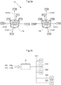
- FIG 3a shows the inventive system 10 which controls the movement of the work tool.
- the system 10 comprises a first and a second hand operated control means 11a, 11b.
- the control means 11a, 11b may for example be a joystick or a three-dimensional computer mouse which are possible to rotate about at least a first control means axis KOA1 and to tilt at least in directions parallel with a second and a third control means axis KOA2, KOA3 which are substantially perpendicular to each other and to the first control means axis KOA1. It may also be possible to adjust the first and the second control means vertically along the vertical first control means axis KOA1. Of course it may also be possible to angle the control means 11 b, 11b in every direction that starts from the first control means axis KOA1 and in such a way continuously control the movement on the second end 4b2 of the outer link arm.
- control means 11a, 11b are one or multiple touch screens where the movements of the work tool 5 are controlled by the sweeping movement of one or multiple fingers across the screen.
- the first hand operated control means 11a is intended to control the position of the second outer link arm end and the second hand operated control means 11b is intended to control the function of the tool.
- the function of the tool it is meant for example its rotation and angle in relation to the outer link arm 4b and an opening or closing movement on tool 5 or grapple.
- the first hand of a driver is used to control the first control means 11a and the second hand of a driver to control the second control means 11b.
- the movements of the first and the second control means 11a, 11b are converted by a control system 12 into control signals SS1, SS2, SS3, SS4, SS5 which activate, deactivate and control control devices V1-V5 which control the movements of the first and the second link arm 4a, 4b and the work tool.
- the control system 12 controls the control devices V1-V3 so that they convert the movements on the second control means 11b to a desired movement on the second outer link arm end 4b2 through control of the movements of the first and the second link arm 4a, 4b relative to each other as well as controls the rotation of the entire digging arm 4 in relation to the top 3.
- a tilting of the first control means 11a in both directions parallel to the first control means axis KOA1 may bring the tip of the digging arm 4, i.e. the second outer link arm end 4b2, away from and towards the driver respectively, function FT1, FT2.
- a tilting of the first control means 11a in both directions parallel to the second control means axis KOA2 may bring the tip of the digging arm 4 to the left and right respectively, function FT3, FT4.This occurs through the entire top 3 including the arm 4 rotating in relation to the bottom carriage 2.
- a rotation of the first control means 11a about the third control means axis KOA3 may rotate the whole construction machine relative to the ground by controlling the digging belts 2a or wheels, function FT5, FT6.
- a dragging and pressing movement, respectively, on the first control means 11a direction parallel to the third control means axis KOA3 may bring the tip of the digging arm 4 upwards and downwards respectively, function FT7, FT8.
- the control system 12 controls with signals SS4, SS5 also the control devices V4, V5 which are associated with the attachment device 6 so that they convert the movements on the second control means 11b to a desired movement and desired function on the attachment device.
- a tilting of the second control means 11b in both directions parallel to the first control means axis KOA may close and open the tool 5 respectively, function FR1, FR2.
- a tilting of the second control means 11b in both directions parallel to the second control means axis KOA2 may bring the left and right side, respectively, of the tool down, i.e. rotate about the second attachment device axis IAA2, function FR3, FR4.
- a rotation of the second control means 11b about the third control means axis KOA3 may rotate the tool about the first attachment device axis IAA1, function FR5, FR6.
- a dragging and pressing movement, respectively, on the second control means 11b with direction parallel to the third control means axis KOA3 may for example entail an opening and closing, respectively, of a grapple (if such is mounted at the tiltrotator), function FR7, FR8.
- FIG. 3b there is shown a schematic flow of control signals SS1, SS2, SS3, SS4, SS5 created by movements FT1-FT8, FR1-FR8 on the control means 11a, 11b via the control system 12 to the control devices V1, V2, V3, V4, V5.
- the control devices V1-V3 control the movements of the link arm 4a, 4b relative to each other and controls the rotation of the entire digging arm 4 in relation to the top 3 and the control devices V4, V5 control the relative movements of the attachment device 6.
Landscapes
- Engineering & Computer Science (AREA)
- Mechanical Engineering (AREA)
- Mining & Mineral Resources (AREA)
- Civil Engineering (AREA)
- General Engineering & Computer Science (AREA)
- Structural Engineering (AREA)
- Life Sciences & Earth Sciences (AREA)
- General Life Sciences & Earth Sciences (AREA)
- Paleontology (AREA)
- Operation Control Of Excavators (AREA)
- Manipulator (AREA)
Description
- The present invention relates to a system and a method for, with a first and a second hand operated control means, controlling movement on a work tool for a construction machine.
- The digging performed with a construction machine is performed with an excavation unit made from two fixed link arms, boom and shaft respectively, as well as a work tool in the form of e.g. a bucket. Until the start of the 1960's, excavation units were maneuvered with steel wires and winches that would pull up the bucket, so called [bucket wheels].
- Today, construction machines such as excavators, are controlled via joysticks in such a way that every input in a joystick controls a specific hydraulic valve. Each hydraulic valve then controls a certain cylinder or engine, which in turn controls the movement in a certain direction on the arm of the excavator (see
Fig. 1 ), as the previous machines were controlled with wires and winches. In order to perform a specific operation, several joints need to be controlled simultaneously why a number of inputs need to be done at the same time. This means that the driver himself coordinates various movements to get the tip and the tool to a desired position. - ln order to bring the bucket straight forward in a horizontal movement at the same time as the bucket is opened, multiple coordinated movements on the joystick are needed. These coordinated movements may be a forward movement on the right joystick, a forward movement on the left joystick as well as a right movement on the right joystick. These three movements must be made simultaneously and in such a way that none of the three valves opens too much or too little, which would mean that it becomes an "unbalanced movement" A device according to the prior art is disclosed in
US2001/0000192 . - This is not a natural and intuitive way of working, and makes the drivers productivity lower and the learning curve longer than it would need to be.
- ln order to control the movements of the work tool, there is also used separate rolls and buttons arranged in the handle of the joystick. The movement of the rolls and the push of the buttons also control a certain hydraulic valve that controls the movement in a certain direction or a certain function of the work tool. These movements or functions may for example be a rotation or a discharge movement. This gives yet another control parameter to be handled simultaneously, which complicates the work of the driver.
- More recently, for the forest industry, there has been introduced a method for crane tip controlling. Crane tip controlling means that the tip of the crane is controlled by a single lever or other control. When the lever is moved forward, the tip of the crane moves in a rectilinear movement forward in the horizontal plane. If the control is moved to the left, the tip of the crane moves to the left, etc. A new control system then controls which valves that need to be activated in order to achieve the desired movement.
- A forest machine, however, works in a completely different way than a construction machine. In the tip of the crane in the forest machine, there is provided a harvesting unit which is completely free hanging from the tip of the crane. The freely hanging unit enables the head to follow and intercept a falling tree without any major forces other than tractor forces need to be absorbed by the lift arm. Without a free hanging unit, the crane risks being subjected to such large torque caused by the falling tree that the machine may break.
- In a construction machine, such as an excavator or a backhoe loader, the work tool must be turned with force in order to perform digging and excavation work. Thus, the work tool is fixed at the outer tip of the digging arm via an attachment device that enables both controlled rotation as well as tilting of the tool.
- A suitable such attachment device is a tiltrotator, which may be likened to the wrist of the excavator arm.
- Since the work tool, when employing crane tip controlling on forest machinery, is hanging loosely, there is no way of controlling the exact location, rotation and position of the tool relative to the tip of the crane.
- An object of the present invention is therefore to provide a system and a method for more intuitive control of both the digging arm of a construction machine and the movement of a work tool in an integrated way.
- Another object is the provided a system and a method that makes it possible to adjust the velocity in the movement based on the desired task.
- The invention thus relates to a system for, with a first and a second hand operated control means, controlling movement on a work tool for a construction machine. The construction machine comprises a lower carriage, a top, a digging arm and a work tool. The digging arm comprises an inner link arm with a first and a second inner link arm end and an outer link arm with a first and a second outer link arm end. One joint connects the top with the first inner link arm end, one joint connects the second inner link arm end with the first outer link arm end and one joint connects the second outer link arm end with the work tool. The work tool is secured in the second outer link arm end via an attachment device that enables controlled rotation and controlled tilting of the work tool in relation to the outer link arm. The system is characterized in that the first hand operated control means is intended to control the position of the second outer link arm end and the second hand operated control means is intended to control the function of the tool.
- Through the above system, control of the movement of the tool of the construction machinery is facilitated. The system is intuitive and simple for the driver to learn. Additionally, it is possible to control both rotation and tilting of the tool with the attachment device.
- According to one aspect, actuators are provided to, via control devices, control the relative movement between the attachment device and the outer link arm, the outer link arm and the inner link arm, as well as between the inner link arm and the top.
- The actuators that are provided may for example be single or double acting hydraulic cylinders, linear motors, screw lines or other devices that may create a relative movement between two parts connected with a joint. If hydraulic cylinders and hydraulic fluid is used, the control devices may be for example hydraulic valves. It is also possible to, as control devices, use electrical servos or other devices in order to, with power supply or otherwise, control the actuators.
- According to another aspect, the system comprises a control system which converts the movements of the first and the second control means to signals that activate, deactivate and control the control devices that control the movements of the first and the second link arm, as well as the control devices provided in the attachment device that control the movement of the work tool.
- According to another aspect, the control system is arranged to control the velocity of the relative movement between the different moving parts, by via the control devices controlling at least one of power supply, pressure or flow in the different actuators and to the attachment device.
- According to another aspect, the attachment device is a tiltrotator and comprises a rotor member intended to control the rotation of the work tool about a first attachment device axis as well as tilting device intended to control the tilt of the work tool about a second attachment device axis substantially perpendicular to the first attachment axis.
- According to another aspect, at least one sensor is provided in the attachment device which measures the relative position between the separate parts of the attachment device and/or the force acting on the control devices that are provided connected with the attachment device.
- The force acting on the control devices is created by, for example, an increased hydraulic pressure or an increased resistance in the movement between the parts.
- According to one aspect, the first and the second control means are possible to tilt in a movement parallel with at least a first and a second control means axis which are substantially perpendicular to each other, and rotate about a third control means axis that is substantially perpendicular to the first and the second control means axis.
- According to one aspect, the first and the second control is possible to adjust in height along the vertical control means axis.
- According to one aspect, a movement on the first control means is intended to control a movement for the second outer link arm end and where a movement on the second control means is intended to control a movement or a function of the tool.
- According to one aspect, the first and the second control means is a touch screen.
- The invention also relates to a method for, with a first and a second hand operated control means, controlling a movement on a work tool of a construction machine, wherein the construction machine comprises a bottom carriage, a top, a digging arm and a work tool. The digging arm comprises an inner link arm with a first and a second inner link arm end and an outer link arm with a first and a second outer link arm end. One joint connects the top with the first inner link arm end, one joint connects the second inner link arm end with the first outer link arm end and one joint connects the second outer link arm end with the work tool. The work tool is attached in the second outer link arm end via an attachment device that enables controlled rotation and controlled tilting of the work tool relative to the outer link arm. The method is characterized in that it comprises the steps of: with the first hand operated control means control the position of the outer end of the outer link arm and with the second hand operated control means control the function of the tool.
- According to another aspect, the method also comprises the step of, with a control system, converting the movements of the first and the second control means into signals that activate, deactivate and control control devices which control the movements of the first and second link arm and the work tool.
- The invention also relates to a computer program product stored in a computer readable medium, which when executed on a computer performs the steps according to the above method.
- AII above aspects or parts of an aspect may be freely combined, as long as the combination is not contradictory.
- The invention will now be described, by way of example, with reference to the accompanying drawings, in which:
-
Fig. 1 shows a previously known system for controlling the movements of a work tool -
Fig. 2a shows a construction machine for which the inventive system is suitable -
Fig. 2b shows a detailed view of the construction machine -
Fig. 3a shows the inventive system which controls movement of the work tool. -
Fig. 3b shows a schematic flow of signals from control means via control systems to valves. - ln the following there is a detailed description of embodiments of the invention. All examples shall be seen as parts of the general description and is therefore generally possible to combine.
- ln
figure 2a there is shown aconstruction machine 1 for which the system is suitable. Theconstruction machine 1 comprises preferably abottom carriage 2 with a drivingbelt 2a, a top 3 as well as adigging arm 4 and awork tool 5. The drivingbelts 2a are of course replaceable with wheels if desired. The diggingarm 4 is made up of a at least one inner 4a and oneouter link arm 4b, boom and shaft respectively, where the digging arm is made up of aninner link arm 4a with a first and a second inner link arm end 4a1, 4a2 and anouter link arm 4b with a first and a second outer link arm end 4b1, 4b2. One joint J1 connects the top 3 with the first inner link arm end 4a1 and one joint J2 connects the second inner link arm end 4a2 with the first outer link arm end 4b1. In theouter link arm 4b of the digging arm, an attachment device 6 for thework tool 5 is attached via an additional joint J4 that enables a rotation about a third substantially horizontal machine axis MA3 that extends through the joint J3. The attachment device 6 enables controlled rotation and controlled tilting of thetool 5. - All joints J1, J2 are operated by hydraulics and enable a rotation about first, second and third substantially horizontal machine axes MA1, MA2, MA3 which extend through the joints J1, J2, J3. At the respective joint J1, J2, J3 there is arranged at least one actuator HC1, HC2, HC3 which is controlled by control devices V1, V2, V3. In machines of today, one of which is shown in
figure 1 , the actuators are hydraulic cylinders and the control devices are hydraulic valves. The control devices V1, V2, V3 may then be provided in the main block in the machine, and be connected to the hydraulic cylinders via hoses. It is also possible to mount the control devices V1, V2, V3 directly at each joint. If instead electrical signals are used to activate, deactivate and control the control devices which control the actuators, electrical wires may be routed between main block and the respective actuator. It is also possible that the actuators are controlled wirelessly. Each control device V1, V2, V3 controls a certain actuator HC1, HC2, HC3 which in turn controls the movement in a certain direction J1, J2, J3 of theexcavator 1. - It is also possible to rotate the
whole top 3 of the construction machine in relation to itsbottom carriage 2, about a substantially vertical machine axis MA4. Through this rotation the basic position of thework tool 5 in relation to the ground may be set. It is also possible to control the whole basic position of the construction machine in relation to the ground, by controlling direction and velocity of the movement of thebelts 2a or, if wheels are used, the rotation of the wheels. - The above mentioned attachment device 6 may be a tiltrotator, which is shown further in
figure 2b . The tiltrotator comprises arotor part 6a which makes it possible to, by force, rotate the tool 360 degrees in relation to theouter link arm 4b around a first attachment device axis IAA1. The rotation occurs with the help of an actuator that is further controlled by a control device V4 which is arranged in therotor member 6a. The tiltrotator also comprises atilting device 6b which makes it possible to angle the tool in relation to a second control means axis IAA2 substantially perpendicular to the first control means axis IAA1. Thesecond tilting device 6b may be another rotor member arranged substantially perpendicular to the first rotor member or one or multiple hydraulic cylinders or other actuators, these also being controlled by control devices V5. - ln the attachment device 6 there is also arranged one or multiple sensors S1, S2, .. Sn which are arranged to sense for example the relative position between the separate parts of the attachment device and the force acting on or the hydraulic pressure in the control devices V4, V5. The sensors may thus sense if and how much the tool is angled. The force that acts on the tool may be read by measuring increased hydraulic pressure or resistance to movement. When the tool encounters rock or similarly for the tool impenetrable material, there is a rapid increase in power in the control devices. When hydraulic cylinders are used as actuators, it is for example possible to strangle the supply of hydraulic fluid to the actuators when a rapid increase in pressure is detected which may prevent a system overload.
- The tilt rotator may also be equipped with fast attachments which enable fast and safe changes of
work tools 5. Thework tool 5 may for example be a bucket, grapple, pallet form, hook, cutter or other suitable tools. It is also possible to integrate a work tool, such as a grapple, in the tiltrotator. Thus the tiltrotator itself may function as a work tool. -
Figure 3a shows theinventive system 10 which controls the movement of the work tool. Thesystem 10 comprises a first and a second hand operated control means 11a, 11b. The control means 11a, 11b may for example be a joystick or a three-dimensional computer mouse which are possible to rotate about at least a first control means axis KOA1 and to tilt at least in directions parallel with a second and a third control means axis KOA2, KOA3 which are substantially perpendicular to each other and to the first control means axis KOA1. It may also be possible to adjust the first and the second control means vertically along the vertical first control means axis KOA1. Of course it may also be possible to angle the control means 11 b, 11b in every direction that starts from the first control means axis KOA1 and in such a way continuously control the movement on the second end 4b2 of the outer link arm. - It is also possible (but not shown) that the control means 11a, 11b are one or multiple touch screens where the movements of the
work tool 5 are controlled by the sweeping movement of one or multiple fingers across the screen. - The first hand operated control means 11a is intended to control the position of the second outer link arm end and the second hand operated control means 11b is intended to control the function of the tool. With the function of the tool, it is meant for example its rotation and angle in relation to the
outer link arm 4b and an opening or closing movement ontool 5 or grapple. Preferably the first hand of a driver is used to control the first control means 11a and the second hand of a driver to control the second control means 11b. - The movements of the first and the second control means 11a, 11b are converted by a
control system 12 into control signals SS1, SS2, SS3, SS4, SS5 which activate, deactivate and control control devices V1-V5 which control the movements of the first and thesecond link arm - The
control system 12 controls the control devices V1-V3 so that they convert the movements on the second control means 11b to a desired movement on the second outer link arm end 4b2 through control of the movements of the first and thesecond link arm entire digging arm 4 in relation to the top 3. - For example, a tilting of the first control means 11a in both directions parallel to the first control means axis KOA1 may bring the tip of the
digging arm 4, i.e. the second outer link arm end 4b2, away from and towards the driver respectively, function FT1, FT2. A tilting of the first control means 11a in both directions parallel to the second control means axis KOA2 may bring the tip of thedigging arm 4 to the left and right respectively, function FT3, FT4.This occurs through the entire top 3 including thearm 4 rotating in relation to thebottom carriage 2. A rotation of the first control means 11a about the third control means axis KOA3 may rotate the whole construction machine relative to the ground by controlling the diggingbelts 2a or wheels, function FT5, FT6. A dragging and pressing movement, respectively, on the first control means 11a direction parallel to the third control means axis KOA3 may bring the tip of thedigging arm 4 upwards and downwards respectively, function FT7, FT8. - The
control system 12 controls with signals SS4, SS5 also the control devices V4, V5 which are associated with the attachment device 6 so that they convert the movements on the second control means 11b to a desired movement and desired function on the attachment device. - For example, a tilting of the second control means 11b in both directions parallel to the first control means axis KOA, may close and open the
tool 5 respectively, function FR1, FR2. A tilting of the second control means 11b in both directions parallel to the second control means axis KOA2 may bring the left and right side, respectively, of the tool down, i.e. rotate about the second attachment device axis IAA2, function FR3, FR4. A rotation of the second control means 11b about the third control means axis KOA3 may rotate the tool about the first attachment device axis IAA1, function FR5, FR6. A dragging and pressing movement, respectively, on the second control means 11b with direction parallel to the third control means axis KOA3 may for example entail an opening and closing, respectively, of a grapple (if such is mounted at the tiltrotator), function FR7, FR8. - ln
figure 3b there is shown a schematic flow of control signals SS1, SS2, SS3, SS4, SS5 created by movements FT1-FT8, FR1-FR8 on the control means 11a, 11b via thecontrol system 12 to the control devices V1, V2, V3, V4, V5. The control devices V1-V3 control the movements of thelink arm entire digging arm 4 in relation to the top 3 and the control devices V4, V5 control the relative movements of the attachment device 6. Of course it is possible to arrange more or fewer control devices than mentioned above to control the movements of the digging arm and the tool.
Claims (13)
- A system for, with a first and a second hand operated control means (11a, 11b), controlling movement on a work tool (5) for a construction machine (1), the construction machine (1) comprising a lower carriage (2), a top (3), a digging arm (4) and a work tool (5),
wherein the digging arm (4) comprises an inner link arm (4a) with a first and a second inner link arm end (4a1, 4a2) and an outer link arm (4b) with a first and a second outer link arm end (4b1, 4b2),
wherein one joint (J1) connects the top (3) with the first inner link arm end (4a1), one joint (J2) connects the second inner link arm end (4a2) with the first outer link arm end (4b1) and one joint (J3) connects the second outer link arm end (4b2) with the work tool (5),
and wherein the work tool (5) is secured in the second outer link arm end (4b1) via an attachment device (6) which enables controlled rotation and controlled tilting of the work tool (5) in relation to the outer link arm (4b);
characterized in that
the first hand operated control means (11a) is intended to control the position of the second outer link arm end (4b2), at least through control of the movements of the inner link arm 4a and the outer link arm 4b relative to each other as well as the rotation of the entire digging arm (4) in relation to the top (3), and
the second hand operated control means (11b) is intended to control the function of the tool (5), comprising controlled rotation and controlled tilting of the work tool (5) in relation to the outer link arm (4b). - The system according to claim 1, wherein actuators (HC1, HC2, HC3) are adapted to via control devices (V1, V2, V3) control the relative movement between the attachment device (6) and the outer link arm (4b), the outer link arm (4b) and the inner link arm (4a) and between the inner link arm (4a) and the top (3).
- The system according to claim 2, comprising a control system (12) which converts the movements of the first and the second control means (11a, 11) to signals (S1, S2, S3) which activate, deactivate and control the control devices (V1, V2, V3) which control the movements of the first and second link arms (4a, 4b) and which activate, deactivate and control the control devices (V4, V5) arranged in the attachment device (6) which control the movement of the work tool (5).
- The system according to claim 3, wherein the control system (12) is adapted to control the velocity of the relative movement between the different moveable link arm parts (4a, 4b) by via the control devices (V1, V2, V3) controlling at least one of power supply, pressure or flow in the different actuators and to the attachment device (6).
- The system according to any of the previous claims, wherein the attachment device (6) is a tiltrotator and comprises a rotor member (6a) intended to control the rotation of the work tool (5) about a first attachment device axis (IAA1) and tilting device (6b) intended to control the tilting of the work tool (5) about a second attachment device axis (IAA2) substantially perpendicular to the first attachment device axis (IAA1).
- The system according to any of the previous claims, wherein at least one sensor (S1, S2, ..Sn) is provided in the attachment device (6) which measures the relative position between the separate parts (6a, 6b) of the attachment device and/or the force that acts upon the control devices (V4, V5) which are provided interconnected with the attachment device (6).
- The system according to any of the previous claims, wherein the first and the second control means (11a, 11b) are possible to tilt in a movement parallel to at least a first and a second control means axis (KOA1, KOA2) which are substantially perpendicular to each other and rotate about a third control means axis (KOA3) which is substantially perpendicular to the first and the second control means axis (KOA1, KOA2).
- The system according to claim 7, wherein the first and the second control means (11a, 11b) is possible to adjust vertically along the third control means axis (KOA3) which is a substantially vertical axis.
- The system according to any of the previous claims, wherein a movement on the first control means (11a) is intended to control a movement for the second outer link arm end (4b) and wherein a movement on the second control means (11b) is intended to control a movement or a function of the tool (5).
- The system according to any of claims 1-6, wherein the first and the second control means (11a, 11b) is a touch screen.
- Method for, with a first and a second hand operated control means (11a, 11b), controlling a movement on a work tool (5) for a construction machine (1), the construction machine (1) comprising a lower carriage (2), a top (3), a digging arm (4) and a work tool (5),
wherein the digging arm (4) comprises an inner link arm (4a) with a first and a second inner link arm end (4a1, 4a2) and an outer link arm (4b) with a first and a second outer link arm end (4b1, 4b2),
wherein one joint (J1) connects the top (3) with the first inner link arm end (4a1), one joint (J2) connects the second inner link arm end (4a2) with the first outer link arm end (4b1) and one joint (J3) connects the second outer link arm end (4b2) with the work tool (5),
and wherein the work tool (5) is secured in the second outer link arm end (4b2) via an attachment device (6) which enables controlled rotation and controlled tilting of the work tool (5) in relation to the outer link arm (4b);
characterized in that the method comprises the steps of:• with the first hand operated control means (11a) controlling the position of the second outer link arm end (4b2), at least through control of the movements of the inner link arm 4a and the outer link arm 4b relative to each other as well as the rotation of the entire digging arm (4) in relation to the top (3), and• with the second hand operated control means (11b) controlling the function of the tool (5), comprising controlled rotation and controlled tilting of the work tool (5) in relation to the outer link arm (4b). - The method according to claim 11 comprising the step of:• with a control system (12) converting the movements (FT1-FT8, FR1-FR8) of the first and the second control means (11a, 11b) into control signals (SS1-SS5) which activate, deactivate and control control devices (V1-V5) which control the movements of the first and the second link arm (4a, 4B) and the work tool (5).
- A computer program product stored on a computer readable medium, which when executed on a computer performs the steps according to the method according to claim 11 or 12.
Applications Claiming Priority (2)
| Application Number | Priority Date | Filing Date | Title |
|---|---|---|---|
| SE1350766A SE537716C2 (en) | 2013-06-25 | 2013-06-25 | Systems, methods and computer programs to control movement of a construction machine's work tools |
| PCT/SE2014/050782 WO2014209209A1 (en) | 2013-06-25 | 2014-06-25 | System and methods for with a first and a second hand operated control, controlling motion on a work tool for a construction machine |
Publications (3)
| Publication Number | Publication Date |
|---|---|
| EP3014026A1 EP3014026A1 (en) | 2016-05-04 |
| EP3014026A4 EP3014026A4 (en) | 2017-02-22 |
| EP3014026B1 true EP3014026B1 (en) | 2019-02-13 |
Family
ID=52142861
Family Applications (1)
| Application Number | Title | Priority Date | Filing Date |
|---|---|---|---|
| EP14818353.6A Active EP3014026B1 (en) | 2013-06-25 | 2014-06-25 | System and methods for with a first and a second hand operated control, controlling motion on a work tool for a construction machine |
Country Status (4)
| Country | Link |
|---|---|
| US (1) | US10202740B2 (en) |
| EP (1) | EP3014026B1 (en) |
| SE (1) | SE537716C2 (en) |
| WO (1) | WO2014209209A1 (en) |
Families Citing this family (18)
| Publication number | Priority date | Publication date | Assignee | Title |
|---|---|---|---|---|
| WO2016110726A1 (en) * | 2015-01-07 | 2016-07-14 | Volvo Construction Equipment Ab | Control method for controlling an excavator and excavator comprising a control unit implementing such a control method |
| KR20170045146A (en) * | 2015-10-16 | 2017-04-26 | 가부시키가이샤 고마쓰 세이사쿠쇼 | Work vehicle, bucket device, and tilt angle acquisition method |
| US9816249B2 (en) | 2016-02-02 | 2017-11-14 | Caterpillar Trimble Control Technologies Llc | Excavating implement heading control |
| US9976279B2 (en) | 2016-02-02 | 2018-05-22 | Caterpillar Trimble Control Technologies Llc | Excavating implement heading control |
| US9976285B2 (en) | 2016-07-27 | 2018-05-22 | Caterpillar Trimble Control Technologies Llc | Excavating implement heading control |
| SE541509C2 (en) * | 2016-11-04 | 2019-10-22 | Rototilt Group Ab | Method and hydraulic system for a tiltrotator with controlled diverter valve for auxiliary tool |
| JP6889579B2 (en) * | 2017-03-15 | 2021-06-18 | 日立建機株式会社 | Work machine |
| JP6969475B2 (en) * | 2018-03-28 | 2021-11-24 | コベルコ建機株式会社 | Construction machinery |
| US20200080277A1 (en) * | 2018-09-10 | 2020-03-12 | Caterpillar Work Tools B.V. | Excavator split connector |
| EP4051840B1 (en) * | 2019-10-31 | 2026-02-11 | Thomas Jansen | Excavator arm |
| GB2593474B (en) * | 2020-03-23 | 2023-12-13 | Bamford Excavators Ltd | An apparatus |
| US11866909B2 (en) * | 2020-11-04 | 2024-01-09 | Caterpillar Inc. | Machine control component with input device to control machine display |
| GB2604354B (en) * | 2021-03-02 | 2023-12-06 | Bamford Excavators Ltd | A Coupling Device |
| US20220341127A1 (en) * | 2021-04-26 | 2022-10-27 | Caterpillar Inc. | Multi-function joystick with asymmetric grip |
| JP7780904B2 (en) * | 2021-09-30 | 2025-12-05 | 株式会社小松製作所 | Systems and methods for controlling a work machine |
| US12359393B2 (en) | 2021-11-22 | 2025-07-15 | Caterpillar Sarl | System and method to support rotation operation of work tool |
| EP4310261B1 (en) | 2022-07-18 | 2026-07-08 | Leica Geosystems Technology A/S | A system for handling the seamless transition of breaklines during an excavation task |
| DE102022132870A1 (en) * | 2022-12-09 | 2024-06-20 | Kiesel Technology Gmbh | Control system for an excavator to control a working device |
Family Cites Families (16)
| Publication number | Priority date | Publication date | Assignee | Title |
|---|---|---|---|---|
| JPH05202532A (en) * | 1992-01-24 | 1993-08-10 | Komatsu Ltd | Work operating device of articulated construction machine |
| US5424623A (en) * | 1993-05-13 | 1995-06-13 | Caterpillar Inc. | Coordinated control for a work implement |
| US6282453B1 (en) * | 1998-12-02 | 2001-08-28 | Caterpillar Inc. | Method for controlling a work implement to prevent interference with a work machine |
| US6481950B1 (en) * | 2000-09-29 | 2002-11-19 | Deere & Company | Control lever assembly |
| US6571902B2 (en) * | 2000-12-28 | 2003-06-03 | Case Corporation | Backhoe auxiliary hydraulics control system |
| US7040044B2 (en) * | 2003-12-15 | 2006-05-09 | Caterpillar S.A.R.L. | Method of modulating a boom assembly to perform in a linear manner |
| US9074352B2 (en) * | 2006-03-27 | 2015-07-07 | John R. Ramun | Universal control scheme for mobile hydraulic equipment and method for achieving the same |
| US7458432B2 (en) * | 2006-06-16 | 2008-12-02 | Deere & Company | Dual lever steering control mechanism |
| US7681686B1 (en) | 2006-09-14 | 2010-03-23 | Deere & Company | Operator control for simultaneous movement of a multifunction machine |
| US7694442B2 (en) * | 2006-11-30 | 2010-04-13 | Caterpillar Inc. | Recommending a machine repositioning distance in an excavating operation |
| US7810260B2 (en) * | 2007-12-21 | 2010-10-12 | Caterpillar Trimble Control Technologies Llc | Control system for tool coupling |
| SE537181C2 (en) * | 2008-10-21 | 2015-02-24 | Svab Hydraulik Ab | Control system and procedure for a tiltrotator |
| US8544562B2 (en) * | 2009-11-25 | 2013-10-01 | 1994 Weyer Family Limited Partnership | Tiltable tool assembly |
| DE202011003220U1 (en) * | 2011-02-25 | 2011-08-11 | Jan Rotard | Control for working machines with boom |
| US20130054097A1 (en) * | 2011-08-22 | 2013-02-28 | Deere And Company | Buried Utility Data with Exclusion Zones |
| CN108425389A (en) * | 2012-06-08 | 2018-08-21 | 住友重机械工业株式会社 | The control method and control device of excavator |
-
2013
- 2013-06-25 SE SE1350766A patent/SE537716C2/en unknown
-
2014
- 2014-06-25 EP EP14818353.6A patent/EP3014026B1/en active Active
- 2014-06-25 WO PCT/SE2014/050782 patent/WO2014209209A1/en not_active Ceased
- 2014-06-25 US US14/900,180 patent/US10202740B2/en active Active
Non-Patent Citations (1)
| Title |
|---|
| None * |
Also Published As
| Publication number | Publication date |
|---|---|
| WO2014209209A1 (en) | 2014-12-31 |
| SE1350766A1 (en) | 2014-12-26 |
| EP3014026A1 (en) | 2016-05-04 |
| US10202740B2 (en) | 2019-02-12 |
| EP3014026A4 (en) | 2017-02-22 |
| US20160145832A1 (en) | 2016-05-26 |
| SE537716C2 (en) | 2015-10-06 |
Similar Documents
| Publication | Publication Date | Title |
|---|---|---|
| WO2014209209A1 (en) | System and methods for with a first and a second hand operated control, controlling motion on a work tool for a construction machine | |
| EP3719212B1 (en) | System for remapping a control signal for excavator arm movement to a rotatory degree of freedom of a tool | |
| US8024095B2 (en) | Adaptive work cycle control system | |
| US9568939B2 (en) | Tactile feedback for joystick position/speed controls | |
| EP2924177B1 (en) | Work vehicle | |
| US9376784B2 (en) | Control system for dual boom machine | |
| US6757994B1 (en) | Automatic tool orientation control for backhoe with extendable dipperstick | |
| US20150002303A1 (en) | System to display remaining payload weight for a truck | |
| AU2004202637A1 (en) | Tactile feedback system for a remotely controlled work machine | |
| US20140067092A1 (en) | Adaptive work cycle control system | |
| JPH108491A (en) | Front control device for construction machinery | |
| US9913437B2 (en) | Velocity-based control of end effector | |
| US10844572B2 (en) | Method of controlling movement of an intelligent boom | |
| KR102378264B1 (en) | working machine | |
| CN107208397A (en) | The rotation control device and its control method of Architectural Equipment | |
| JP7677129B2 (en) | Construction machine drive device, construction machine equipped with the same, and construction machine system | |
| JP7798253B2 (en) | Work machines, information processing devices | |
| CN115917090A (en) | work machinery | |
| WO2023276421A1 (en) | Construction machine | |
| DE202011003220U1 (en) | Control for working machines with boom | |
| US20140305012A1 (en) | Single boom system having dual arm linkage | |
| JP4444884B2 (en) | Construction machine and control device used for construction machine | |
| CN108716230B (en) | engineering vehicle | |
| KR20120131386A (en) | excavator | |
| KR20210143400A (en) | Apparatus and method for controlling bucket position of Excavator |
Legal Events
| Date | Code | Title | Description |
|---|---|---|---|
| PUAI | Public reference made under article 153(3) epc to a published international application that has entered the european phase |
Free format text: ORIGINAL CODE: 0009012 |
|
| 17P | Request for examination filed |
Effective date: 20151209 |
|
| AK | Designated contracting states |
Kind code of ref document: A1 Designated state(s): AL AT BE BG CH CY CZ DE DK EE ES FI FR GB GR HR HU IE IS IT LI LT LU LV MC MK MT NL NO PL PT RO RS SE SI SK SM TR |
|
| AX | Request for extension of the european patent |
Extension state: BA ME |
|
| DAX | Request for extension of the european patent (deleted) | ||
| A4 | Supplementary search report drawn up and despatched |
Effective date: 20170124 |
|
| RIC1 | Information provided on ipc code assigned before grant |
Ipc: E02F 9/26 20060101ALI20170118BHEP Ipc: E02F 3/43 20060101AFI20170118BHEP Ipc: E02F 9/20 20060101ALI20170118BHEP Ipc: E02F 3/36 20060101ALI20170118BHEP Ipc: E02F 3/32 20060101ALI20170118BHEP |
|
| GRAP | Despatch of communication of intention to grant a patent |
Free format text: ORIGINAL CODE: EPIDOSNIGR1 |
|
| STAA | Information on the status of an ep patent application or granted ep patent |
Free format text: STATUS: GRANT OF PATENT IS INTENDED |
|
| INTG | Intention to grant announced |
Effective date: 20180824 |
|
| GRAS | Grant fee paid |
Free format text: ORIGINAL CODE: EPIDOSNIGR3 |
|
| GRAA | (expected) grant |
Free format text: ORIGINAL CODE: 0009210 |
|
| STAA | Information on the status of an ep patent application or granted ep patent |
Free format text: STATUS: THE PATENT HAS BEEN GRANTED |
|
| AK | Designated contracting states |
Kind code of ref document: B1 Designated state(s): AL AT BE BG CH CY CZ DE DK EE ES FI FR GB GR HR HU IE IS IT LI LT LU LV MC MK MT NL NO PL PT RO RS SE SI SK SM TR |
|
| REG | Reference to a national code |
Ref country code: GB Ref legal event code: FG4D |
|
| REG | Reference to a national code |
Ref country code: CH Ref legal event code: EP Ref country code: AT Ref legal event code: REF Ref document number: 1096315 Country of ref document: AT Kind code of ref document: T Effective date: 20190215 |
|
| REG | Reference to a national code |
Ref country code: IE Ref legal event code: FG4D |
|
| REG | Reference to a national code |
Ref country code: DE Ref legal event code: R096 Ref document number: 602014041054 Country of ref document: DE |
|
| REG | Reference to a national code |
Ref country code: LT Ref legal event code: MG4D |
|
| REG | Reference to a national code |
Ref country code: NL Ref legal event code: MP Effective date: 20190213 |
|
| PG25 | Lapsed in a contracting state [announced via postgrant information from national office to epo] |
Ref country code: PT Free format text: LAPSE BECAUSE OF FAILURE TO SUBMIT A TRANSLATION OF THE DESCRIPTION OR TO PAY THE FEE WITHIN THE PRESCRIBED TIME-LIMIT Effective date: 20190613 Ref country code: NL Free format text: LAPSE BECAUSE OF FAILURE TO SUBMIT A TRANSLATION OF THE DESCRIPTION OR TO PAY THE FEE WITHIN THE PRESCRIBED TIME-LIMIT Effective date: 20190213 Ref country code: LT Free format text: LAPSE BECAUSE OF FAILURE TO SUBMIT A TRANSLATION OF THE DESCRIPTION OR TO PAY THE FEE WITHIN THE PRESCRIBED TIME-LIMIT Effective date: 20190213 Ref country code: NO Free format text: LAPSE BECAUSE OF FAILURE TO SUBMIT A TRANSLATION OF THE DESCRIPTION OR TO PAY THE FEE WITHIN THE PRESCRIBED TIME-LIMIT Effective date: 20190513 Ref country code: SE Free format text: LAPSE BECAUSE OF FAILURE TO SUBMIT A TRANSLATION OF THE DESCRIPTION OR TO PAY THE FEE WITHIN THE PRESCRIBED TIME-LIMIT Effective date: 20190213 Ref country code: FI Free format text: LAPSE BECAUSE OF FAILURE TO SUBMIT A TRANSLATION OF THE DESCRIPTION OR TO PAY THE FEE WITHIN THE PRESCRIBED TIME-LIMIT Effective date: 20190213 |
|
| PG25 | Lapsed in a contracting state [announced via postgrant information from national office to epo] |
Ref country code: GR Free format text: LAPSE BECAUSE OF FAILURE TO SUBMIT A TRANSLATION OF THE DESCRIPTION OR TO PAY THE FEE WITHIN THE PRESCRIBED TIME-LIMIT Effective date: 20190514 Ref country code: IS Free format text: LAPSE BECAUSE OF FAILURE TO SUBMIT A TRANSLATION OF THE DESCRIPTION OR TO PAY THE FEE WITHIN THE PRESCRIBED TIME-LIMIT Effective date: 20190613 Ref country code: BG Free format text: LAPSE BECAUSE OF FAILURE TO SUBMIT A TRANSLATION OF THE DESCRIPTION OR TO PAY THE FEE WITHIN THE PRESCRIBED TIME-LIMIT Effective date: 20190513 Ref country code: RS Free format text: LAPSE BECAUSE OF FAILURE TO SUBMIT A TRANSLATION OF THE DESCRIPTION OR TO PAY THE FEE WITHIN THE PRESCRIBED TIME-LIMIT Effective date: 20190213 Ref country code: LV Free format text: LAPSE BECAUSE OF FAILURE TO SUBMIT A TRANSLATION OF THE DESCRIPTION OR TO PAY THE FEE WITHIN THE PRESCRIBED TIME-LIMIT Effective date: 20190213 Ref country code: HR Free format text: LAPSE BECAUSE OF FAILURE TO SUBMIT A TRANSLATION OF THE DESCRIPTION OR TO PAY THE FEE WITHIN THE PRESCRIBED TIME-LIMIT Effective date: 20190213 |
|
| REG | Reference to a national code |
Ref country code: AT Ref legal event code: MK05 Ref document number: 1096315 Country of ref document: AT Kind code of ref document: T Effective date: 20190213 |
|
| PG25 | Lapsed in a contracting state [announced via postgrant information from national office to epo] |
Ref country code: IT Free format text: LAPSE BECAUSE OF FAILURE TO SUBMIT A TRANSLATION OF THE DESCRIPTION OR TO PAY THE FEE WITHIN THE PRESCRIBED TIME-LIMIT Effective date: 20190213 Ref country code: SK Free format text: LAPSE BECAUSE OF FAILURE TO SUBMIT A TRANSLATION OF THE DESCRIPTION OR TO PAY THE FEE WITHIN THE PRESCRIBED TIME-LIMIT Effective date: 20190213 Ref country code: ES Free format text: LAPSE BECAUSE OF FAILURE TO SUBMIT A TRANSLATION OF THE DESCRIPTION OR TO PAY THE FEE WITHIN THE PRESCRIBED TIME-LIMIT Effective date: 20190213 Ref country code: AL Free format text: LAPSE BECAUSE OF FAILURE TO SUBMIT A TRANSLATION OF THE DESCRIPTION OR TO PAY THE FEE WITHIN THE PRESCRIBED TIME-LIMIT Effective date: 20190213 Ref country code: DK Free format text: LAPSE BECAUSE OF FAILURE TO SUBMIT A TRANSLATION OF THE DESCRIPTION OR TO PAY THE FEE WITHIN THE PRESCRIBED TIME-LIMIT Effective date: 20190213 Ref country code: EE Free format text: LAPSE BECAUSE OF FAILURE TO SUBMIT A TRANSLATION OF THE DESCRIPTION OR TO PAY THE FEE WITHIN THE PRESCRIBED TIME-LIMIT Effective date: 20190213 Ref country code: CZ Free format text: LAPSE BECAUSE OF FAILURE TO SUBMIT A TRANSLATION OF THE DESCRIPTION OR TO PAY THE FEE WITHIN THE PRESCRIBED TIME-LIMIT Effective date: 20190213 Ref country code: RO Free format text: LAPSE BECAUSE OF FAILURE TO SUBMIT A TRANSLATION OF THE DESCRIPTION OR TO PAY THE FEE WITHIN THE PRESCRIBED TIME-LIMIT Effective date: 20190213 |
|
| REG | Reference to a national code |
Ref country code: DE Ref legal event code: R097 Ref document number: 602014041054 Country of ref document: DE |
|
| PG25 | Lapsed in a contracting state [announced via postgrant information from national office to epo] |
Ref country code: PL Free format text: LAPSE BECAUSE OF FAILURE TO SUBMIT A TRANSLATION OF THE DESCRIPTION OR TO PAY THE FEE WITHIN THE PRESCRIBED TIME-LIMIT Effective date: 20190213 Ref country code: SM Free format text: LAPSE BECAUSE OF FAILURE TO SUBMIT A TRANSLATION OF THE DESCRIPTION OR TO PAY THE FEE WITHIN THE PRESCRIBED TIME-LIMIT Effective date: 20190213 |
|
| PLBE | No opposition filed within time limit |
Free format text: ORIGINAL CODE: 0009261 |
|
| STAA | Information on the status of an ep patent application or granted ep patent |
Free format text: STATUS: NO OPPOSITION FILED WITHIN TIME LIMIT |
|
| PG25 | Lapsed in a contracting state [announced via postgrant information from national office to epo] |
Ref country code: AT Free format text: LAPSE BECAUSE OF FAILURE TO SUBMIT A TRANSLATION OF THE DESCRIPTION OR TO PAY THE FEE WITHIN THE PRESCRIBED TIME-LIMIT Effective date: 20190213 |
|
| 26N | No opposition filed |
Effective date: 20191114 |
|
| PG25 | Lapsed in a contracting state [announced via postgrant information from national office to epo] |
Ref country code: MC Free format text: LAPSE BECAUSE OF FAILURE TO SUBMIT A TRANSLATION OF THE DESCRIPTION OR TO PAY THE FEE WITHIN THE PRESCRIBED TIME-LIMIT Effective date: 20190213 |
|
| REG | Reference to a national code |
Ref country code: CH Ref legal event code: PL |
|
| GBPC | Gb: european patent ceased through non-payment of renewal fee |
Effective date: 20190625 |
|
| PG25 | Lapsed in a contracting state [announced via postgrant information from national office to epo] |
Ref country code: SI Free format text: LAPSE BECAUSE OF FAILURE TO SUBMIT A TRANSLATION OF THE DESCRIPTION OR TO PAY THE FEE WITHIN THE PRESCRIBED TIME-LIMIT Effective date: 20190213 |
|
| REG | Reference to a national code |
Ref country code: BE Ref legal event code: MM Effective date: 20190630 |
|
| PG25 | Lapsed in a contracting state [announced via postgrant information from national office to epo] |
Ref country code: TR Free format text: LAPSE BECAUSE OF FAILURE TO SUBMIT A TRANSLATION OF THE DESCRIPTION OR TO PAY THE FEE WITHIN THE PRESCRIBED TIME-LIMIT Effective date: 20190213 |
|
| PG25 | Lapsed in a contracting state [announced via postgrant information from national office to epo] |
Ref country code: GB Free format text: LAPSE BECAUSE OF NON-PAYMENT OF DUE FEES Effective date: 20190625 Ref country code: IE Free format text: LAPSE BECAUSE OF NON-PAYMENT OF DUE FEES Effective date: 20190625 |
|
| PG25 | Lapsed in a contracting state [announced via postgrant information from national office to epo] |
Ref country code: LI Free format text: LAPSE BECAUSE OF NON-PAYMENT OF DUE FEES Effective date: 20190630 Ref country code: CH Free format text: LAPSE BECAUSE OF NON-PAYMENT OF DUE FEES Effective date: 20190630 Ref country code: BE Free format text: LAPSE BECAUSE OF NON-PAYMENT OF DUE FEES Effective date: 20190630 Ref country code: LU Free format text: LAPSE BECAUSE OF NON-PAYMENT OF DUE FEES Effective date: 20190625 |
|
| PG25 | Lapsed in a contracting state [announced via postgrant information from national office to epo] |
Ref country code: CY Free format text: LAPSE BECAUSE OF FAILURE TO SUBMIT A TRANSLATION OF THE DESCRIPTION OR TO PAY THE FEE WITHIN THE PRESCRIBED TIME-LIMIT Effective date: 20190213 |
|
| PG25 | Lapsed in a contracting state [announced via postgrant information from national office to epo] |
Ref country code: HU Free format text: LAPSE BECAUSE OF FAILURE TO SUBMIT A TRANSLATION OF THE DESCRIPTION OR TO PAY THE FEE WITHIN THE PRESCRIBED TIME-LIMIT; INVALID AB INITIO Effective date: 20140625 Ref country code: MT Free format text: LAPSE BECAUSE OF FAILURE TO SUBMIT A TRANSLATION OF THE DESCRIPTION OR TO PAY THE FEE WITHIN THE PRESCRIBED TIME-LIMIT Effective date: 20190213 |
|
| PG25 | Lapsed in a contracting state [announced via postgrant information from national office to epo] |
Ref country code: MK Free format text: LAPSE BECAUSE OF FAILURE TO SUBMIT A TRANSLATION OF THE DESCRIPTION OR TO PAY THE FEE WITHIN THE PRESCRIBED TIME-LIMIT Effective date: 20190213 |
|
| PGFP | Annual fee paid to national office [announced via postgrant information from national office to epo] |
Ref country code: DE Payment date: 20260618 Year of fee payment: 13 |
|
| PGFP | Annual fee paid to national office [announced via postgrant information from national office to epo] |
Ref country code: FR Payment date: 20260616 Year of fee payment: 13 |