EP3013756B1 - Water treatment system - Google Patents
Water treatment system Download PDFInfo
- Publication number
- EP3013756B1 EP3013756B1 EP14818622.4A EP14818622A EP3013756B1 EP 3013756 B1 EP3013756 B1 EP 3013756B1 EP 14818622 A EP14818622 A EP 14818622A EP 3013756 B1 EP3013756 B1 EP 3013756B1
- Authority
- EP
- European Patent Office
- Prior art keywords
- ozone
- water
- control valve
- bypass control
- input line
- Prior art date
- Legal status (The legal status is an assumption and is not a legal conclusion. Google has not performed a legal analysis and makes no representation as to the accuracy of the status listed.)
- Not-in-force
Links
- XLYOFNOQVPJJNP-UHFFFAOYSA-N water Substances O XLYOFNOQVPJJNP-UHFFFAOYSA-N 0.000 title claims description 128
- CBENFWSGALASAD-UHFFFAOYSA-N Ozone Chemical compound [O-][O+]=O CBENFWSGALASAD-UHFFFAOYSA-N 0.000 claims description 147
- 238000004891 communication Methods 0.000 claims description 29
- 239000012530 fluid Substances 0.000 claims description 29
- 238000002156 mixing Methods 0.000 claims description 17
- 238000011144 upstream manufacturing Methods 0.000 claims description 16
- 230000000063 preceeding effect Effects 0.000 claims 1
- 239000007789 gas Substances 0.000 description 22
- 239000013049 sediment Substances 0.000 description 10
- 239000003570 air Substances 0.000 description 7
- 239000007864 aqueous solution Substances 0.000 description 7
- MHAJPDPJQMAIIY-UHFFFAOYSA-N Hydrogen peroxide Chemical compound OO MHAJPDPJQMAIIY-UHFFFAOYSA-N 0.000 description 6
- QVGXLLKOCUKJST-UHFFFAOYSA-N atomic oxygen Chemical compound [O] QVGXLLKOCUKJST-UHFFFAOYSA-N 0.000 description 6
- 239000000203 mixture Substances 0.000 description 6
- 239000001301 oxygen Substances 0.000 description 6
- 229910052760 oxygen Inorganic materials 0.000 description 6
- 239000000356 contaminant Substances 0.000 description 5
- 238000000034 method Methods 0.000 description 5
- 239000002245 particle Substances 0.000 description 5
- 239000002244 precipitate Substances 0.000 description 5
- 230000009471 action Effects 0.000 description 4
- 230000000694 effects Effects 0.000 description 4
- 230000008569 process Effects 0.000 description 4
- 230000009182 swimming Effects 0.000 description 4
- 239000000645 desinfectant Substances 0.000 description 3
- 239000003651 drinking water Substances 0.000 description 3
- 239000007788 liquid Substances 0.000 description 3
- 238000004519 manufacturing process Methods 0.000 description 3
- 238000006385 ozonation reaction Methods 0.000 description 3
- 230000001105 regulatory effect Effects 0.000 description 3
- VEXZGXHMUGYJMC-UHFFFAOYSA-N Hydrochloric acid Chemical compound Cl VEXZGXHMUGYJMC-UHFFFAOYSA-N 0.000 description 2
- 238000011001 backwashing Methods 0.000 description 2
- 230000008901 benefit Effects 0.000 description 2
- 235000012206 bottled water Nutrition 0.000 description 2
- 239000006227 byproduct Substances 0.000 description 2
- 230000008859 change Effects 0.000 description 2
- 238000001914 filtration Methods 0.000 description 2
- 239000012535 impurity Substances 0.000 description 2
- 238000005259 measurement Methods 0.000 description 2
- 239000007800 oxidant agent Substances 0.000 description 2
- 230000009467 reduction Effects 0.000 description 2
- 230000001954 sterilising effect Effects 0.000 description 2
- 238000012546 transfer Methods 0.000 description 2
- 239000002699 waste material Substances 0.000 description 2
- 241000894006 Bacteria Species 0.000 description 1
- 241000700605 Viruses Species 0.000 description 1
- 239000012080 ambient air Substances 0.000 description 1
- 238000009360 aquaculture Methods 0.000 description 1
- 244000144974 aquaculture Species 0.000 description 1
- 230000005540 biological transmission Effects 0.000 description 1
- 238000006243 chemical reaction Methods 0.000 description 1
- 239000013626 chemical specie Substances 0.000 description 1
- 239000003795 chemical substances by application Substances 0.000 description 1
- 238000005660 chlorination reaction Methods 0.000 description 1
- 239000003086 colorant Substances 0.000 description 1
- 230000001276 controlling effect Effects 0.000 description 1
- 238000005202 decontamination Methods 0.000 description 1
- 230000003588 decontaminative effect Effects 0.000 description 1
- 238000001514 detection method Methods 0.000 description 1
- 238000010586 diagram Methods 0.000 description 1
- 238000004090 dissolution Methods 0.000 description 1
- 235000020188 drinking water Nutrition 0.000 description 1
- 230000002708 enhancing effect Effects 0.000 description 1
- 239000003344 environmental pollutant Substances 0.000 description 1
- 230000005484 gravity Effects 0.000 description 1
- 238000002347 injection Methods 0.000 description 1
- 239000007924 injection Substances 0.000 description 1
- 238000002955 isolation Methods 0.000 description 1
- 238000012423 maintenance Methods 0.000 description 1
- 238000012544 monitoring process Methods 0.000 description 1
- 230000033116 oxidation-reduction process Effects 0.000 description 1
- 230000001590 oxidative effect Effects 0.000 description 1
- 244000052769 pathogen Species 0.000 description 1
- 231100000719 pollutant Toxicity 0.000 description 1
- 239000000047 product Substances 0.000 description 1
- 238000000746 purification Methods 0.000 description 1
- 150000003254 radicals Chemical class 0.000 description 1
- 238000011012 sanitization Methods 0.000 description 1
- 238000004659 sterilization and disinfection Methods 0.000 description 1
- 238000003756 stirring Methods 0.000 description 1
- 239000000126 substance Substances 0.000 description 1
- 238000012360 testing method Methods 0.000 description 1
- 231100000331 toxic Toxicity 0.000 description 1
- 230000002588 toxic effect Effects 0.000 description 1
Images



Classifications
-
- C—CHEMISTRY; METALLURGY
- C02—TREATMENT OF WATER, WASTE WATER, SEWAGE, OR SLUDGE
- C02F—TREATMENT OF WATER, WASTE WATER, SEWAGE, OR SLUDGE
- C02F1/00—Treatment of water, waste water, or sewage
- C02F1/72—Treatment of water, waste water, or sewage by oxidation
- C02F1/78—Treatment of water, waste water, or sewage by oxidation with ozone
-
- C—CHEMISTRY; METALLURGY
- C02—TREATMENT OF WATER, WASTE WATER, SEWAGE, OR SLUDGE
- C02F—TREATMENT OF WATER, WASTE WATER, SEWAGE, OR SLUDGE
- C02F1/00—Treatment of water, waste water, or sewage
- C02F1/50—Treatment of water, waste water, or sewage by addition or application of a germicide or by oligodynamic treatment
-
- E—FIXED CONSTRUCTIONS
- E04—BUILDING
- E04H—BUILDINGS OR LIKE STRUCTURES FOR PARTICULAR PURPOSES; SWIMMING OR SPLASH BATHS OR POOLS; MASTS; FENCING; TENTS OR CANOPIES, IN GENERAL
- E04H4/00—Swimming or splash baths or pools
- E04H4/12—Devices or arrangements for circulating water, i.e. devices for removal of polluted water, cleaning baths or for water treatment
- E04H4/1281—Devices for distributing chemical products in the water of swimming pools
-
- C—CHEMISTRY; METALLURGY
- C02—TREATMENT OF WATER, WASTE WATER, SEWAGE, OR SLUDGE
- C02F—TREATMENT OF WATER, WASTE WATER, SEWAGE, OR SLUDGE
- C02F2103/00—Nature of the water, waste water, sewage or sludge to be treated
- C02F2103/42—Nature of the water, waste water, sewage or sludge to be treated from bathing facilities, e.g. swimming pools
-
- C—CHEMISTRY; METALLURGY
- C02—TREATMENT OF WATER, WASTE WATER, SEWAGE, OR SLUDGE
- C02F—TREATMENT OF WATER, WASTE WATER, SEWAGE, OR SLUDGE
- C02F2201/00—Apparatus for treatment of water, waste water or sewage
- C02F2201/78—Details relating to ozone treatment devices
-
- C—CHEMISTRY; METALLURGY
- C02—TREATMENT OF WATER, WASTE WATER, SEWAGE, OR SLUDGE
- C02F—TREATMENT OF WATER, WASTE WATER, SEWAGE, OR SLUDGE
- C02F2209/00—Controlling or monitoring parameters in water treatment
- C02F2209/03—Pressure
-
- C—CHEMISTRY; METALLURGY
- C02—TREATMENT OF WATER, WASTE WATER, SEWAGE, OR SLUDGE
- C02F—TREATMENT OF WATER, WASTE WATER, SEWAGE, OR SLUDGE
- C02F2209/00—Controlling or monitoring parameters in water treatment
- C02F2209/38—Gas flow rate
-
- C—CHEMISTRY; METALLURGY
- C02—TREATMENT OF WATER, WASTE WATER, SEWAGE, OR SLUDGE
- C02F—TREATMENT OF WATER, WASTE WATER, SEWAGE, OR SLUDGE
- C02F2301/00—General aspects of water treatment
- C02F2301/02—Fluid flow conditions
- C02F2301/024—Turbulent
-
- C—CHEMISTRY; METALLURGY
- C02—TREATMENT OF WATER, WASTE WATER, SEWAGE, OR SLUDGE
- C02F—TREATMENT OF WATER, WASTE WATER, SEWAGE, OR SLUDGE
- C02F2301/00—General aspects of water treatment
- C02F2301/04—Flow arrangements
- C02F2301/043—Treatment of partial or bypass streams
-
- C—CHEMISTRY; METALLURGY
- C02—TREATMENT OF WATER, WASTE WATER, SEWAGE, OR SLUDGE
- C02F—TREATMENT OF WATER, WASTE WATER, SEWAGE, OR SLUDGE
- C02F2303/00—Specific treatment goals
- C02F2303/04—Disinfection
-
- E—FIXED CONSTRUCTIONS
- E04—BUILDING
- E04H—BUILDINGS OR LIKE STRUCTURES FOR PARTICULAR PURPOSES; SWIMMING OR SPLASH BATHS OR POOLS; MASTS; FENCING; TENTS OR CANOPIES, IN GENERAL
- E04H4/00—Swimming or splash baths or pools
- E04H4/12—Devices or arrangements for circulating water, i.e. devices for removal of polluted water, cleaning baths or for water treatment
Definitions
- the present invention relates to a water treatment system.
- the present invention relates to a water treatment system for treating swimming pool or spa water.
- the invention may be deployed for treating water and other liquids in other fields of usage.
- Ozone gas provides a powerful disinfectant and oxidant when used for the treatment of water.
- Ozone is environmentally friendly, and decomposes to the more stable diatomic allotrope of oxygen (O2), during water treatment, minimising harmful bi-products.
- Ozone provides a strong, broad spectrum disinfectant, and is an effective agent to inactivate harmful protozoa, microbes and other pathogens.
- Ozone is commercially made by passing oxygen through ultraviolet light or alternatively using an electrical discharge.
- the most common ozone production technique involves corona discharge, whereby a high voltage electrical discharge is passed across a gap through which filtered dry air flows.
- Ozone when used for water purification is generally created onsite and added to the water by bubble contact.
- Some of the advantages of ozone include the production of fewer dangerous by-products and the absence of taste and odor problems which are prevalent in comparison when chlorination is used to treat water.
- Another advantage of ozone is that it leaves no residual disinfectant in the water after treatment has occurred. Ozonation can be used to treat organic and inorganic contaminants, including bacteria, viruses and protozons.
- ozonation provides an effective means for water treatment in various applications from swimming pools to potable drinking water
- drawbacks in existing ozonation systems One problem is the need to efficiently mix the ozone source with the water requiring treatment. For disinfection to occur, the ozone molecules must physically contact the contaminant to react with it. If an inadequate degree of mixing occurs, there is a risk of the ozone not coming into contact with parcels of water, and accordingly only partially treating the water.
- a further problem with ozone treatment is that the water will almost always need to be filtered or settled after ozone exposure, as ozone tends to coagulate and precipitate various impurities present in the water.
- the size of the ozone gas bubble released into the water for treatment is an important factor.
- a bubble size of 2 to 3 microns is generally desirable, and for good gas to liquid transfer, the smallest achievable bubble size is generally preferable.
- Ozone gas is difficult to efficiently mix into an aqueous solution. In order to reach the full potential of the ozone to treat the water, saturation of the ozone gas in the aqueous solution is generally required.
- the document JP 2005046831 discloses an ozone water treatment system comprising mixing and stirring means, an input line, an ozone supply unit including an ozone generator, an ejector in fluid communication with the ozone supply unit, a pressure adjusting means including a valve whose opening degree can be adjusted, an ozone gas supply line connecting the ozone generator and the ejector, a water passage branch line in fluid communication with the input line and the ejector through a water passage switching valve, a pressurizing pump and said pressure adjusting means, pressure detection means for detecting the pressure across the ejector, and a pressure pump P located in the branch line upstream relative to the pressure adjusting means.
- the document US 2005/103725 relates to a system for sanitizing and refilling a potable water system onboard a transport vehicle including an ozone contact tank, a supply conduit, an ozone generator and injector, a branching line, an ozone line in fluid communication with the ozone generator and injector and the ozone contact tank, an automated valve, a particulate filter and a differential pressure gauge for detecting the pressure across said particulate filter.
- the ozone input rate which is controlled either on or off via the ozone monitor, can not be regulated.
- the document DE 10308123 concerns a system for treating water including a sterilizing apparatus including a sterilizing tube, an ultraviolet lamp and an ozone transmission pipe. It also includes, on the on hand, a water inlet, an ozone gas injection apparatus including a main pipe with water inlet end and water outlet end, a Venturi tube and a check valve and, on the other hand, a monitoring apparatus including a flow meter used for measuring the flow rate and accumulated water flow to calculate the service life of a filter and a pressure sensor for detecting the pressure difference between the Venturi tube's water inlet and water outlet ends. The pressure sensor is used for producing output signals that are transmitted to an electronic board which then generates ultraviolet lamp control signals to monitor the turning on and off of the latter. The switch on the lamp is controlled by the flow rate. It also includes a flow meter for measuring the flow rate and accumulated water.
- the document WO 2012/103597 concerns a water treatment apparatus for treating a body of water including a control box and multicyclone unit containing a cartridge filter, a main feed line having an upstream end in fluid communication with the body of water and a downstream end in fluid communication with the multicylone unit, a Venturi injector, an ozone supply line and a by-pass valve allowing to control manually the flow of watter through the feed line and a flow line containing a combination of ozone and hydrogen peroxide or hydrochloric acid chemicals.
- the control box contains an ozone generating unit and the Venturi valve acts on the feed line and controls the rate at which ozone is added to the water.
- the Venturi injector creates a vacuum in the ozone supply line from the ozone generating unit.
- a vacuum gauge located in the control box assist the user in controlling the strength of the vacuum for achieving the regulated flow rate of ozone, hydrogen peroxide and hydrochloric.
- a vacuum gauge allows the control of the strength of the vacuum created by a Venturi injector for achieving the regulated flow rate of ozone, hydrogen peroxide and hydrochloric
- the ozone flow rate can only be measured manually using a vacuum meter, requiring the ozone inlet pipework to be disconnected for testing at regular intervals.
- the present invention provides a water treatment system comprising:
- the ozone supply line extends between the ozone injector and the bypass control valve.
- the water treatment system further comprises a pressure differential measuring device adapted to measure a pressure differential between a first location in the input line upstream relative to the bypass control valve, and a second location in the input line downstream relative to the bypass control valve.
- the first location is preferably positioned in the input line between the bypass control valve and a connection with the branching line.
- the pressure differential measuring device includes :
- the bypass control valve partially open positions preferably correspond to measurements on a gauge identified on the pressure indicator, enabling selection of a desired flow rate through the ozone injector to achieve a desired pressure differential and ozone delivery rate.
- the ozone gas generation system preferably includes an ultra-violet ozone generation system.
- the water mixing unit is preferably a multi-cyclone unit.
- the water treatment system further preferably comprises two positions, a first position of the pressure indicator preferably indicating that a filter is blocked, and a second position of the pressure indicator preferably indicates that the input line is blocked.
- a water treatment system 10 for treating water, and in particular the water of swimming pools and spas. However, it will be appreciated that the water treatment system 10 may be used to treat potable water and other water reservoirs or other liquids.
- Water to be treated is drawn from an outlet port located in the swimming pool or body of water using a pump.
- the water may initially be filtered to remove sedimentary contaminants and other large particulate pollutants.
- the water is then directed through an input line 12 of the water treatment system 10.
- the input line 12 is in fluid communication with a bypass control valve 14.
- a branching line 16 is connected to the input line 12, generally upstream of the bypass control valve 14, and the branching line 16 is in fluid communication with an ozone injector 30.
- An ozone supply line 32 extends between the ozone injector 30 and the bypass control valve 14. Accordingly, as shown in Fig. 1 the branching line 16 and the ozone supply line 32 define a fluid flow path that diverges away from the input line 12 and subsequently reconverges with the input line 12.
- the bypass control valve 14 can be switched between an open position, a closed position, and one or more intermediate partially open positions. In the open position, and partially open positions, water is able to flow through the branching line 16, the ozone supply line 32 and the water subsequently passes through the bypass control valve 14, to rejoin the input line 12, further downstream of the bypass control valve 14.
- the input line 12 Downstream of the bypass control valve 14, the input line 12 is in fluid communication with a water mixing unit 50 adapted to promote turbulence in the water.
- the water mixing unit 50 is a multi-cyclone centrifugal sediment filter 50.
- the multi-cyclone sediment filter 50 is disclosed in PCT/IB2008/001633 ( WO/2008/155649 ) in the name of the present applicant, Waterco Limited. However, it will be appreciated by those skilled in the art that other suitable multi-cyclone sediment filters 50 may be used.
- multi-cyclone sediment filter 50 Different models can be used, depending on the volume of water to be treated.
- the multi-cyclone sediment filter 50 may be provided with 3,72 square meter (40 sq ft) cartridges, 6,98 square meter (75 sq ft) cartridges or another suitable sized cartridge.
- the multi-cyclone sediment filter 50 enhances the ozone or other gas mixing within the flow of water.
- Multi-cyclone filters 50 there are various models of Multi-cyclone filters 50 which can be used, in the system 10, such as those manufactured by Waterco Limited under the brand MC50, MC40, MC12 Plus and Ultra, MC16 Plus and Ultra.
- MC12, MC16 Plus and Ultra have additional chambers on top of the Multi-cyclone with 40 sq ft and 75 sq ft. cartridge elements for finer filtration.
- the Multi-cyclone sediment filter 50 can also be used with or without a filtration cartridge in the chamber to enhance ozone or gas mixing.
- An ozone generation device 20, in the form of a UV ozone generation device 20 is located in or near the system 10.
- the ozone generation device 20 generates ozone by passing air across a vacuum ultra violet lamp, a process referred to as VUV ozone generation.
- the generated ozone is then directed to an ozone injector 30 in the form of a dynamic injector 30.
- the dynamic injector 30 is in fluid communication with the ozone supply line 32.
- the dynamic injector 30 is a device that allows for the suitable transfer of the ozone gas into the water flow.
- it is preferably a Venturi injector 30, having an upstream water inlet in fluid communication with the branching line 16 and a downstream water outlet in fluid communication with the ozone supply line 32.
- the dynamic injector 30 includes one or more ozone/air inlet ports. The Venturi effect resulting from water flowing across the restriction, causes a negative pressure, which draws gas (in this case a mix of air/ozone) into dynamic injector 30 through the ozone/air inlet ports.
- the water leaving the dynamic injector 30 in the ozone supply line 32 includes the mix of air/ozone and water.
- the bypass control valve 14 When the bypass control valve 14 is in an open position, the mix of air/ozone and water is sucked through the valve 14 and into the input line 12, where it continues to the multi-cyclone sediment filter 50.
- Cyclonic action created within the multi-cyclone 50 creates high turbulence which in turn increases the dissolution of ozone gas.
- the way in which the multi-cyclone 50 achieves high turbulence through cyclonic action has not previously been applied to the process of mixing ozone gas into an aqueous solution. Cyclonic action in the multi-cyclone 50 acts as a contact chamber enhancing the mixing process of ozone or other gases in the water.
- the water treatment system 10 includes an ozone administering and measuring unit 80 which is depicted in isolation in Figs. 3 to 5 .
- the ozone administering and measuring unit 80 is defined by the branching line 16, the dynamic injector 30, the ozone supply line 32 (which extends between the dynamic injector 30 and the bypass control valve 14), the bypass control valve 14 and a portion of the water input line 12, and a pressure indicator 90.
- the two ends of the ozone administering and measuring unit 80 which form part of the water input line 12, are provided with screw connectors 82. This enables the ozone administering and measuring unit 80 to be readily removed from the water treatment system 10 for maintenance or replacement purposes.
- the branching line 16 includes two screw plugs 84.
- the screw plugs 84 permit one or more sensors to be added to the ozone administering and measuring unit 80.
- a PH and/or ORP (oxidation reduction potential) sensor may be installed in the ozone administering and measuring unit 80 at the screw plug 84 which is located closest to the dynamic injector 30.
- the other screw plug 84 which is located furthest from the dynamic injector 30 may be used for inserting a grounding sensor into the ozone administering and measuring unit 80.
- the ozone administering and measuring unit 80 includes a pressure indicator 90 associated with a pressure differential measuring device 91, which are best seen in Fig. 4 .
- the pressure differential measuring device 91 includes a body or housing 93 which is in fluid communication with a first tube 92 and a second tube 94.
- the first and second tubes 92, 94 are typically manufactured from small diameter flexible conduit.
- the first tube 92 has a first end connected to an upstream side of the housing 93.
- the first tube 92 is also connected at an opposing second end to the water input line 12 between the node where the branching line 16 diverges and the bypass control valve 14.
- the second tube 94 has a first end connected to a downstream side of the housing 93.
- the second tube 94 is also connected at an opposing second end to the water input line 12, downstream of the bypass control valve 14 (between the bypass control valve 14 and the multi-cyclone centrifugal sediment filter 50).
- the pressure indicator 90 is able to measure the pressure differences between the first tube 92 and the second tube 94, to thereby measure the pressure differential between two points in the ozone administering and measuring unit 80.
- the two measurement points are located on the input line 12 on opposing sides of the bypass control valve 14.
- the pressure indicator 90 includes a user display gauge 96.
- the display gauge 96 includes three different coloured or labelled regions.
- the display gauge 96 may be divided into 3 different segments, reading "CLEAN”, "CHANGE” and "DIRTY”.
- the bypass control valve 14 has a user interface in the form of corresponding coloured or labelled regions 100.
- bypass control valve 14 When the bypass control valve 14 is open, water is permitted to divert through the branching line 16 where it is mixed with ozone provided by the dynamic injector 30. Alternatively, when the bypass control valve 14 is closed, all of the water passes from the water input line 12 directly through the bypass control valve 14, without passing the ozone injector 30. In the fully closed bypass valve 14 position, water is prevented from flowing through the branching line 16 or the ozone supply line 32. Accordingly, in the bypass switch 14 closed position, ozone is not mixed with the water.
- the user is able to adjust the pressure differential across the valve 14, which results in the desired dosing of ozone mixing within the water treatment system 10.
- An intermediate position of the valve 14 (depicted as a yellow coloured position of three possible positions shown in Fig. 4 ) is a partially closed position.
- some of the water bypasses through the branching line 16, and through the dynamic ozone injector 30, creating a vacuum which sucks ozone from the ozonator 20.
- Ozone is fed through a small port on the dynamic injector 30. The ozone is mixed into the water flow and continues with the water through the ozone supply line 32, and continues to the multi-cyclone 50 or mixing device to thoroughly mix the ozone into the water.
- a pressure differential exists across the inlet and outlets of the bypass valve 14 inlet.
- the pressure differential corresponds to a vacuum force which is created and which is proportional to the amount of ozone injected into the water stream, through the ozone supply line 32.
- the pressure display gauge 96 indicates a first position, corresponding to the word "CLEAN", which is also associated with a colour such as green (as depicted in Fig. 4 ), this indicates to the user that a final filter (not shown) which is located downstream of the water treatment system 10 is clogged and requires back washing.
- the pressure change results from reduced flow downstream of the water treatment system 10, and increased pressure for the water to pass through the return line to the pool.
- the display gauge 96 is in this first or “green” position, this indicates that backwashing should be conducted to clean the final filter.
- pressure display gauge 96 indicates a second position corresponding to the word "DIRTY" which is also associated with a colour such as red (as depicted in Fig. 4 ), this indicates that too much vacuum force is being created. This indicates that the input line 12 is blocked thereby bypassing all (or most) of the water through branching line 16. If this occurs, the user can attempt adjustment of the bypass control valve 14 to control ozone dosing.
- the display gauge identifies the second position, the input line 12 should be cleared. Whilst the water treatment system 10 can operate with the display gauge 96 in the second, or "red" position, this is not ideal, and preferably the hydraulic problem in the line should be rectified.
- Corresponding colours such as red, yellow and green as identified on the pressure display gauge 96 may also be applied to the labelled regions 100 of the bypass control valve 14 for user convenience.
- the user decides whether any activity is required, such as adjusting the bypass control valve if it is deemed necessary. Alternatively, the user may decide to attend to the removal of a blockage if identified upstream or downstream of the bypass control valve 14.
- the bypass control valve 14 and/or the pressure differential measuring device 91 may be in communication with the ozone generator 20 to send a signal to the ozone generator 20 to switch off when the bypass control valve 14 is closed or power on when the bypass control valve 14 is open.
- the multi-cyclone 50 efficiently combines the mixing of ozone gas and the removal of precipitates in one device.
- the water treatment system 10 can be applied to other gasses such as (but not restricted to) oxygen and ambient air. Such applications could be applied to the aquaculture industry (but not limited to) to complete more efficient saturation of oxygen into water while also removing suspended particles.
- the multi-cyclone 50 removes particles from the water, reducing the amount of contaminants in the water, and minimising the amount of ozone required to effectively treat the water.
- the water treatment system 10 provides efficient saturation of ozone gas, or other gases, into an aqueous solution.
- the water treatment system 10 allows for the removal of suspended particles with a specific gravity higher than the aqueous solution being treated.
- the multi-cyclone sediment filter 50 allows waste that has settled after ozone exposure to be captured, as ozone tends to coagulate and precipitate various impurities present in the water.
- the system 10 allows a user to selectively adjust the amount of ozone being mixed with the water depending on water conditions.
Landscapes
- Engineering & Computer Science (AREA)
- Water Supply & Treatment (AREA)
- Life Sciences & Earth Sciences (AREA)
- Hydrology & Water Resources (AREA)
- Environmental & Geological Engineering (AREA)
- Chemical & Material Sciences (AREA)
- Organic Chemistry (AREA)
- Architecture (AREA)
- Civil Engineering (AREA)
- Structural Engineering (AREA)
- Treatment Of Water By Oxidation Or Reduction (AREA)
Description
- The present invention relates to a water treatment system. In particular, the present invention relates to a water treatment system for treating swimming pool or spa water. However, it will be appreciated by those skilled in the art that the invention may be deployed for treating water and other liquids in other fields of usage.
- Ozone gas (O3) provides a powerful disinfectant and oxidant when used for the treatment of water. Ozone is environmentally friendly, and decomposes to the more stable diatomic allotrope of oxygen (O2), during water treatment, minimising harmful bi-products.
- Each three atom ozone molecule is relatively unstable and readily gives up one atom of oxygen providing a powerful oxidizing agent which is toxic to most waterborne organisms. Ozone provides a strong, broad spectrum disinfectant, and is an effective agent to inactivate harmful protozoa, microbes and other pathogens.
- Ozone is commercially made by passing oxygen through ultraviolet light or alternatively using an electrical discharge. The most common ozone production technique involves corona discharge, whereby a high voltage electrical discharge is passed across a gap through which filtered dry air flows.
- Ozone when used for water purification is generally created onsite and added to the water by bubble contact. Some of the advantages of ozone include the production of fewer dangerous by-products and the absence of taste and odor problems which are prevalent in comparison when chlorination is used to treat water. Another advantage of ozone is that it leaves no residual disinfectant in the water after treatment has occurred. Ozonation can be used to treat organic and inorganic contaminants, including bacteria, viruses and protozons.
- Whilst ozonation provides an effective means for water treatment in various applications from swimming pools to potable drinking water, there are inherent drawbacks in existing ozonation systems. One problem is the need to efficiently mix the ozone source with the water requiring treatment. For disinfection to occur, the ozone molecules must physically contact the contaminant to react with it. If an inadequate degree of mixing occurs, there is a risk of the ozone not coming into contact with parcels of water, and accordingly only partially treating the water.
- This drawback is compounded by the short life span of the ozone molecule, which typically degrades in a short period of time back to the diatomic allotrope of oxygen (O2), after the third atom, disassociates from the ozone particle as a free radical. As such, the ozone molecules normally only last for a few minutes or less after adding to water. Accordingly, if the ozone molecules do not come into contact with the contaminants shortly after being introduced into the water flow, the likelihood of effective water treatment is significantly reduced.
- In addition, on account of the added electrical input and hence costs associated with producing the ozone, it is preferable to minimise the ozone production, and not produce surplus ozone beyond what is required for adequate decontamination.
- A further problem with ozone treatment is that the water will almost always need to be filtered or settled after ozone exposure, as ozone tends to coagulate and precipitate various impurities present in the water.
- The size of the ozone gas bubble released into the water for treatment is an important factor. A bubble size of 2 to 3 microns is generally desirable, and for good gas to liquid transfer, the smallest achievable bubble size is generally preferable. Ozone gas is difficult to efficiently mix into an aqueous solution. In order to reach the full potential of the ozone to treat the water, saturation of the ozone gas in the aqueous solution is generally required.
- The document
JP 2005046831 - The system of the document
JP 2005046831 - The document
US 2005/103725 relates to a system for sanitizing and refilling a potable water system onboard a transport vehicle including an ozone contact tank, a supply conduit, an ozone generator and injector, a branching line, an ozone line in fluid communication with the ozone generator and injector and the ozone contact tank, an automated valve, a particulate filter and a differential pressure gauge for detecting the pressure across said particulate filter. - However, in the system of the document
US 2005/103725 , the ozone input rate, which is controlled either on or off via the ozone monitor, can not be regulated. - The document
DE 10308123 concerns a system for treating water including a sterilizing apparatus including a sterilizing tube, an ultraviolet lamp and an ozone transmission pipe. It also includes, on the on hand, a water inlet, an ozone gas injection apparatus including a main pipe with water inlet end and water outlet end, a Venturi tube and a check valve and, on the other hand, a monitoring apparatus including a flow meter used for measuring the flow rate and accumulated water flow to calculate the service life of a filter and a pressure sensor for detecting the pressure difference between the Venturi tube's water inlet and water outlet ends. The pressure sensor is used for producing output signals that are transmitted to an electronic board which then generates ultraviolet lamp control signals to monitor the turning on and off of the latter. The switch on the lamp is controlled by the flow rate. It also includes a flow meter for measuring the flow rate and accumulated water. - However, in the document
DE 10308123 , where the pressure sensor, in the flow meter placed within the Venturi tube, is used to determine a flow rate which then turns the switch of the ultraviolet lamp (the ozone unit) on or off, it is not possible to regulate the flow rate of ozone. - The document
WO 2012/103597 concerns a water treatment apparatus for treating a body of water including a control box and multicyclone unit containing a cartridge filter, a main feed line having an upstream end in fluid communication with the body of water and a downstream end in fluid communication with the multicylone unit, a Venturi injector, an ozone supply line and a by-pass valve allowing to control manually the flow of watter through the feed line and a flow line containing a combination of ozone and hydrogen peroxide or hydrochloric acid chemicals. The control box contains an ozone generating unit and the Venturi valve acts on the feed line and controls the rate at which ozone is added to the water. The Venturi injector creates a vacuum in the ozone supply line from the ozone generating unit. A vacuum gauge located in the control box assist the user in controlling the strength of the vacuum for achieving the regulated flow rate of ozone, hydrogen peroxide and hydrochloric. - However, in such a system disclosed in the document
WO 2012/103597 , in which a vacuum gauge allows the control of the strength of the vacuum created by a Venturi injector for achieving the regulated flow rate of ozone, hydrogen peroxide and hydrochloric, it is operationally quite difficult, or impossible, to measure only the ozone flow rate and to regulate the latter. In addition, the ozone flow rate can only be measured manually using a vacuum meter, requiring the ozone inlet pipework to be disconnected for testing at regular intervals. - It is an object of the present invention to substantially overcome or at least ameliorate one or more of the above disadvantages, or to provide a useful alternative.
- In a first aspect, the present invention provides a water treatment system comprising:
- a water mixing unit adapted to promote water turbulence;
- an input line having an upstream end adapted to be in fluid communication with a body of water to be treated, and a downstream end in fluid communication with the water mixing unit;
- an ozone gas generation system,
- an ozone injector adapted to be connected in fluid communication with an ozone gas generation system, said ozone injector includes a Venturi nozzle and a gas inlet port located at or near a restriction formed in the Venturi nozzle;
- a branching line in fluid communication with the input line and the ozone injector, said branching line being connected to the input line upstream of a bypass control valve;
- an ozone supply line in fluid communication with the ozone injector; and wherein
- the bypass control valve in fluid communication with the ozone supply line and the input line and adapted to be selectively switched between an open position, one or more partially open positions and a closed position, wherein water is prevented from flowing from the ozone supply line through the bypass control valve and into the input line when the bypass control valve is in the closed position. In the open position, and partially open positions, water is able to flow through the branching line, the ozone supply line and the water subsequently passes through the bypass control valve, to rejoin the input line, further downstream of the bypass control valve.
- The ozone supply line extends between the ozone injector and the bypass control valve.
- The water treatment system further comprises a pressure differential measuring device adapted to measure a pressure differential between a first location in the input line upstream relative to the bypass control valve, and a second location in the input line downstream relative to the bypass control valve.
- The first location is preferably positioned in the input line between the bypass control valve and a connection with the branching line.
- The pressure differential measuring device includes :
- a housing;
- a first tube in fluid communication with an upstream side of the housing and the water input line upstream of the bypass control valve; a second tube in fluid communication with a downstream side of the housing and the water input line downstream of the bypass control valve, and a pressure indicator adapted to provide a user with an indication of the measured pressure differential. The pressure indicator includes a user display gauge.
- The bypass control valve partially open positions preferably correspond to measurements on a gauge identified on the pressure indicator, enabling selection of a desired flow rate through the ozone injector to achieve a desired pressure differential and ozone delivery rate.
- The ozone gas generation system preferably includes an ultra-violet ozone generation system.
- The water mixing unit is preferably a multi-cyclone unit.
- The water treatment system further preferably comprises two positions, a first position of the pressure indicator preferably indicating that a filter is blocked, and a second position of the pressure indicator preferably indicates that the input line is blocked.
- A preferred embodiment of the invention will now be described by way of specific example with reference to the accompanying drawings, in which:
-
Fig. 1 is a schematic diagram depicting a water treatment system; -
Fig. 2 is a schematic view depicting the water treatment system ofFig. 1 ; -
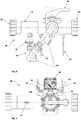
Fig. 3 is a front view of an ozone administering and measuring unit of the water treatment system; -
Fig. 4 is a top view of the ozone administering and measuring unit ofFig. 3 ; and -
Fig. 5 is an end view of the ozone administering and measuring unit ofFig. 3 . - A
water treatment system 10 is disclosed for treating water, and in particular the water of swimming pools and spas. However, it will be appreciated that thewater treatment system 10 may be used to treat potable water and other water reservoirs or other liquids. - Water to be treated is drawn from an outlet port located in the swimming pool or body of water using a pump. The water may initially be filtered to remove sedimentary contaminants and other large particulate pollutants. The water is then directed through an
input line 12 of thewater treatment system 10. - The
input line 12 is in fluid communication with abypass control valve 14. A branchingline 16 is connected to theinput line 12, generally upstream of thebypass control valve 14, and the branchingline 16 is in fluid communication with anozone injector 30. Anozone supply line 32 extends between theozone injector 30 and thebypass control valve 14. Accordingly, as shown inFig. 1 the branchingline 16 and theozone supply line 32 define a fluid flow path that diverges away from theinput line 12 and subsequently reconverges with theinput line 12. - The
bypass control valve 14 can be switched between an open position, a closed position, and one or more intermediate partially open positions. In the open position, and partially open positions, water is able to flow through the branchingline 16, theozone supply line 32 and the water subsequently passes through thebypass control valve 14, to rejoin theinput line 12, further downstream of thebypass control valve 14. - Downstream of the
bypass control valve 14, theinput line 12 is in fluid communication with awater mixing unit 50 adapted to promote turbulence in the water. In the embodiment described herein, thewater mixing unit 50 is a multi-cyclonecentrifugal sediment filter 50. Themulti-cyclone sediment filter 50 is disclosed inPCT/IB2008/001633 (WO/2008/155649 ) in the name of the present applicant, Waterco Limited. However, it will be appreciated by those skilled in the art that other suitable multi-cyclone sediment filters 50 may be used. - Different models of
multi-cyclone sediment filter 50 can be used, depending on the volume of water to be treated. For example, themulti-cyclone sediment filter 50 may be provided with 3,72 square meter (40 sq ft) cartridges, 6,98 square meter (75 sq ft) cartridges or another suitable sized cartridge. Themulti-cyclone sediment filter 50 enhances the ozone or other gas mixing within the flow of water. - There are various models of Multi-cyclone filters 50 which can be used, in the
system 10, such as those manufactured by Waterco Limited under the brand MC50, MC40, MC12 Plus and Ultra, MC16 Plus and Ultra. - MC12, MC16 Plus and Ultra have additional chambers on top of the Multi-cyclone with 40 sq ft and 75 sq ft. cartridge elements for finer filtration. The
Multi-cyclone sediment filter 50 can also be used with or without a filtration cartridge in the chamber to enhance ozone or gas mixing. - An
ozone generation device 20, in the form of a UVozone generation device 20 is located in or near thesystem 10. Theozone generation device 20 generates ozone by passing air across a vacuum ultra violet lamp, a process referred to as VUV ozone generation. - The generated ozone is then directed to an
ozone injector 30 in the form of adynamic injector 30. Thedynamic injector 30 is in fluid communication with theozone supply line 32. Thedynamic injector 30 is a device that allows for the suitable transfer of the ozone gas into the water flow. In particular, it is preferably aVenturi injector 30, having an upstream water inlet in fluid communication with the branchingline 16 and a downstream water outlet in fluid communication with theozone supply line 32. There is a restriction defined by a reduction in cross-sectional area within thedynamic injector 30, and this provides a Venturi pressure reduction effect. Thedynamic injector 30 includes one or more ozone/air inlet ports. The Venturi effect resulting from water flowing across the restriction, causes a negative pressure, which draws gas (in this case a mix of air/ozone) intodynamic injector 30 through the ozone/air inlet ports. - The water leaving the
dynamic injector 30 in theozone supply line 32 includes the mix of air/ozone and water. When thebypass control valve 14 is in an open position, the mix of air/ozone and water is sucked through thevalve 14 and into theinput line 12, where it continues to themulti-cyclone sediment filter 50. - Cyclonic action created within the
multi-cyclone 50 creates high turbulence which in turn increases the dissolution of ozone gas. The way in which themulti-cyclone 50 achieves high turbulence through cyclonic action has not previously been applied to the process of mixing ozone gas into an aqueous solution. Cyclonic action in the multi-cyclone 50 acts as a contact chamber enhancing the mixing process of ozone or other gases in the water. - During the process of adding ozone gas to aqueous solutions, there are some situations in which chemical species precipitate out of the aqueous solution. The removal of the precipitate is facilitated by the cyclonic action within the multi-cyclone 50, which is designed to capture suspended particles. Accordingly, the waste by-products generated by reaction with the ozone are advantageously removed by the cyclone effect within the
multi-cyclone 50. - The
water treatment system 10 includes an ozone administering and measuringunit 80 which is depicted in isolation inFigs. 3 to 5 . The ozone administering and measuringunit 80 is defined by the branchingline 16, thedynamic injector 30, the ozone supply line 32 (which extends between thedynamic injector 30 and the bypass control valve 14), thebypass control valve 14 and a portion of thewater input line 12, and apressure indicator 90. - As depicted in
Fig. 3 for example, the two ends of the ozone administering and measuringunit 80, which form part of thewater input line 12, are provided withscrew connectors 82. This enables the ozone administering and measuringunit 80 to be readily removed from thewater treatment system 10 for maintenance or replacement purposes. - The branching
line 16 includes two screw plugs 84. The screw plugs 84 permit one or more sensors to be added to the ozone administering and measuringunit 80. For example, a PH and/or ORP (oxidation reduction potential) sensor may be installed in the ozone administering and measuringunit 80 at thescrew plug 84 which is located closest to thedynamic injector 30. The other screw plug 84 which is located furthest from thedynamic injector 30 may be used for inserting a grounding sensor into the ozone administering and measuringunit 80. - The ozone administering and measuring
unit 80 includes apressure indicator 90 associated with a pressuredifferential measuring device 91, which are best seen inFig. 4 . The pressuredifferential measuring device 91 includes a body orhousing 93 which is in fluid communication with afirst tube 92 and asecond tube 94. The first andsecond tubes - As illustrated in
Figs. 3 and 4 , thefirst tube 92 has a first end connected to an upstream side of thehousing 93. Thefirst tube 92 is also connected at an opposing second end to thewater input line 12 between the node where the branchingline 16 diverges and thebypass control valve 14. - As illustrated in
Fig. 3 and 4 , thesecond tube 94 has a first end connected to a downstream side of thehousing 93. Thesecond tube 94 is also connected at an opposing second end to thewater input line 12, downstream of the bypass control valve 14 (between thebypass control valve 14 and the multi-cyclone centrifugal sediment filter 50). - The
pressure indicator 90 is able to measure the pressure differences between thefirst tube 92 and thesecond tube 94, to thereby measure the pressure differential between two points in the ozone administering and measuringunit 80. The two measurement points are located on theinput line 12 on opposing sides of thebypass control valve 14. - The
pressure indicator 90 includes auser display gauge 96. In the embodiment depicted in the drawings, thedisplay gauge 96 includes three different coloured or labelled regions. For example thedisplay gauge 96 may be divided into 3 different segments, reading "CLEAN", "CHANGE" and "DIRTY". Similarly, thebypass control valve 14 has a user interface in the form of corresponding coloured or labelledregions 100. - When the
bypass control valve 14 is open, water is permitted to divert through the branchingline 16 where it is mixed with ozone provided by thedynamic injector 30. Alternatively, when thebypass control valve 14 is closed, all of the water passes from thewater input line 12 directly through thebypass control valve 14, without passing theozone injector 30. In the fullyclosed bypass valve 14 position, water is prevented from flowing through the branchingline 16 or theozone supply line 32. Accordingly, in thebypass switch 14 closed position, ozone is not mixed with the water. - Accordingly, by adjusting the
bypass control valve 14, the user is able to adjust the pressure differential across thevalve 14, which results in the desired dosing of ozone mixing within thewater treatment system 10. - The operation of the
bypass control valve 14 will now be described. An intermediate position of the valve 14 (depicted as a yellow coloured position of three possible positions shown inFig. 4 ) is a partially closed position. When thevalve 14 is in the intermediate position, some of the water bypasses through the branchingline 16, and through thedynamic ozone injector 30, creating a vacuum which sucks ozone from theozonator 20. Ozone is fed through a small port on thedynamic injector 30. The ozone is mixed into the water flow and continues with the water through theozone supply line 32, and continues to the multi-cyclone 50 or mixing device to thoroughly mix the ozone into the water. - When the
bypass control valve 14 is open or partially open, a pressure differential exists across the inlet and outlets of thebypass valve 14 inlet. The pressure differential corresponds to a vacuum force which is created and which is proportional to the amount of ozone injected into the water stream, through theozone supply line 32. - When the
pressure display gauge 96 indicates a first position, corresponding to the word "CLEAN", which is also associated with a colour such as green (as depicted inFig. 4 ), this indicates to the user that a final filter (not shown) which is located downstream of thewater treatment system 10 is clogged and requires back washing. The pressure change results from reduced flow downstream of thewater treatment system 10, and increased pressure for the water to pass through the return line to the pool. When thedisplay gauge 96 is in this first or "green" position, this indicates that backwashing should be conducted to clean the final filter. - When
pressure display gauge 96 indicates a second position corresponding to the word "DIRTY" which is also associated with a colour such as red (as depicted inFig. 4 ), this indicates that too much vacuum force is being created. This indicates that theinput line 12 is blocked thereby bypassing all (or most) of the water through branchingline 16. If this occurs, the user can attempt adjustment of thebypass control valve 14 to control ozone dosing. When the display gauge identifies the second position, theinput line 12 should be cleared. Whilst thewater treatment system 10 can operate with thedisplay gauge 96 in the second, or "red" position, this is not ideal, and preferably the hydraulic problem in the line should be rectified. - Corresponding colours such as red, yellow and green as identified on the
pressure display gauge 96 may also be applied to the labelledregions 100 of thebypass control valve 14 for user convenience. - Based on the reading of the
display gauge 96, the user decides whether any activity is required, such as adjusting the bypass control valve if it is deemed necessary. Alternatively, the user may decide to attend to the removal of a blockage if identified upstream or downstream of thebypass control valve 14. - The
bypass control valve 14 and/or the pressuredifferential measuring device 91 may be in communication with theozone generator 20 to send a signal to theozone generator 20 to switch off when thebypass control valve 14 is closed or power on when thebypass control valve 14 is open. - The multi-cyclone 50 efficiently combines the mixing of ozone gas and the removal of precipitates in one device.
- The
water treatment system 10 can be applied to other gasses such as (but not restricted to) oxygen and ambient air. Such applications could be applied to the aquaculture industry (but not limited to) to complete more efficient saturation of oxygen into water while also removing suspended particles. - Advantageously, the multi-cyclone 50 removes particles from the water, reducing the amount of contaminants in the water, and minimising the amount of ozone required to effectively treat the water.
- The
water treatment system 10 provides efficient saturation of ozone gas, or other gases, into an aqueous solution. - The
water treatment system 10 allows for the removal of suspended particles with a specific gravity higher than the aqueous solution being treated. - Advantageously, the
multi-cyclone sediment filter 50 allows waste that has settled after ozone exposure to be captured, as ozone tends to coagulate and precipitate various impurities present in the water. - Advantageously, the
system 10 allows a user to selectively adjust the amount of ozone being mixed with the water depending on water conditions.
Claims (6)
- A water treatment system (10) comprising:a water mixing unit (50) adapted to promote water turbulence;an input line (12) having an upstream end adapted to be in fluid communication with a body of water to be treated, and a downstream end in fluid communication with the water mixing unit (50);an ozone gas generation system (20),an ozone injector (30) connected in fluid communication with the ozone gas generation system (20); said ozone injector includes a Venturi nozzle and a gas inlet port located at or near a restriction formed in the Venturi nozzle;a branching line (16) in fluid communication with the input line (12) and the ozone injector (30), said branching line (16) being connected to the input line (12) upstream of a bypass control valve (14);an ozone supply line (32) in fluid communication with the ozone injector (30);wherein the ozone supply line (32) extends between the ozone injector (30) and the bypass control valve (14),and wherein said water treatment system further comprises- the bypass control valve (14) being in fluid communication with the ozone supply line (32) and the input line (12) and adapted to be selectively switched between an open position, one or more partially open positions and a closed position, wherein water is prevented from flowing from the ozone supply line through the bypass control valve and into the input line when the bypass control valve is in the closed position; in the open position, and partially open positions, water being able to flow through the branching line (16), the ozone supply line (32) and the water subsequently passes through the bypass control valve (14), to rejoin the input line (12), further downstream of the bypass control valve (14),- a pressure differential measuring device (91) adapted to measure a pressure differential between a first location in the input line (12) upstream relative to the bypass control valve (14), and a second location in the input line (12) downstream relative to the bypass control valve (14), said pressure differential measuring device (91) including :a housing (93);a first tube (92) in fluid communication with an upstream side of the housing and the water input line (12) upstream of the bypass control valve (14); anda second tube (94) in fluid communication with a downstream side of the housing and the water input line (12) downstream of the bypass control valve (14),a pressure indicator (90) adapted to provide a user with an indication of the measured pressure differential, said pressure indicator including a display gauge (96).
- The water treatment system (10) of claim 1, wherein the first location is positioned in the input line (12) between the bypass control valve (14) and a connection with the branching line (16).
- The water treatment system (10) of any one of the preceeding claims, wherein the user display gauge (96) is configured to display pressure readings corresponding to positions of the bypass control valve.
- The water treatment system (10) of any one of the preceding claims, wherein the ozone gas generation system includes an ultra-violet ozone generation system.
- The water treatment system (10) of any one of the preceding claims, wherein the water mixing unit is a multi cyclone unit.
- The water treatment system (10) of any one of the preceding claims, wherein the user display gauge (96) is configured to indicate if a filter of the water treatment system is blocked;
further wherein the user display gauge (96) is configured to indicate if the input line (12) is blocked.
Applications Claiming Priority (2)
| Application Number | Priority Date | Filing Date | Title |
|---|---|---|---|
| AU2013902389A AU2013902389A0 (en) | 2013-06-28 | Water treatment system | |
| PCT/AU2014/000657 WO2014205486A1 (en) | 2013-06-28 | 2014-06-26 | Water treatment system |
Publications (3)
| Publication Number | Publication Date |
|---|---|
| EP3013756A1 EP3013756A1 (en) | 2016-05-04 |
| EP3013756A4 EP3013756A4 (en) | 2016-12-21 |
| EP3013756B1 true EP3013756B1 (en) | 2019-02-20 |
Family
ID=52140657
Family Applications (1)
| Application Number | Title | Priority Date | Filing Date |
|---|---|---|---|
| EP14818622.4A Not-in-force EP3013756B1 (en) | 2013-06-28 | 2014-06-26 | Water treatment system |
Country Status (5)
| Country | Link |
|---|---|
| US (1) | US9809473B2 (en) |
| EP (1) | EP3013756B1 (en) |
| CN (1) | CN105339311B (en) |
| AU (1) | AU2014302015B2 (en) |
| WO (1) | WO2014205486A1 (en) |
Families Citing this family (7)
| Publication number | Priority date | Publication date | Assignee | Title |
|---|---|---|---|---|
| US11767242B2 (en) * | 2017-12-29 | 2023-09-26 | Surfplasma, Inc. | Compact portable plasma reactor |
| CN112569815B (en) * | 2019-09-30 | 2022-09-09 | 芜湖美的厨卫电器制造有限公司 | Micro-nano bubble water generating device, control method and storage medium thereof |
| US11905191B1 (en) | 2021-02-17 | 2024-02-20 | Aquastar Pool Products, Inc. | Ozone injector device |
| US11358888B1 (en) | 2021-02-17 | 2022-06-14 | Aquastar Pool Products, Inc. | Ozone injector device |
| USD972069S1 (en) * | 2021-02-17 | 2022-12-06 | Aquastar Pool Products, Inc. | Ozone injector device |
| FR3134682B1 (en) * | 2022-04-22 | 2024-10-04 | Air Liquide | Method and installation for regulating oxygen doping in animal drinking water |
| USD1100985S1 (en) * | 2025-01-14 | 2025-11-04 | Hai Zhong | Pool pump |
Family Cites Families (11)
| Publication number | Priority date | Publication date | Assignee | Title |
|---|---|---|---|---|
| WO2003016224A1 (en) * | 1999-07-12 | 2003-02-27 | Joseph Gargas | Combined ozonation and electrolytic chlorination water purification system |
| TW200407265A (en) | 2002-11-14 | 2004-05-16 | Senno Technology Inc | Water treatment system combining ozone injection apparatus and monitoring apparatus |
| JP4003231B2 (en) * | 2003-07-15 | 2007-11-07 | 株式会社安川電機 | Ozone water treatment equipment |
| US7883622B1 (en) * | 2003-09-23 | 2011-02-08 | Barnes Ronald L | Water treatment methods and systems using combinations of ozone and chlorine generators |
| US7311817B2 (en) | 2003-11-14 | 2007-12-25 | Semler Industries, Inc. | System and method for sanitizing and refilling a potable water system onboard a transport vehicle |
| EP1695939A1 (en) * | 2005-02-25 | 2006-08-30 | HomeFlow Switzerland Distribution SA | A device and a method for purifying a liquid with ozone and recirculation |
| US20080116149A1 (en) * | 2006-10-05 | 2008-05-22 | Dick Paul H | System and method for the disinfection of irrigation water |
| US7922668B2 (en) * | 2007-03-16 | 2011-04-12 | Aerobic Water Works LLC | Aerobic spa system |
| WO2008155649A1 (en) * | 2007-06-20 | 2008-12-24 | Waterco Limited | Multi-cyclone sediment filter |
| GB201018265D0 (en) * | 2010-10-29 | 2010-12-15 | Clean Water Systems Ltd | Fluid treatment apparatus |
| AU2011101664B4 (en) * | 2011-02-04 | 2012-05-03 | Waterco Limited | Water Treatment System |
-
2014
- 2014-06-26 US US14/899,341 patent/US9809473B2/en not_active Expired - Fee Related
- 2014-06-26 CN CN201480036914.1A patent/CN105339311B/en not_active Expired - Fee Related
- 2014-06-26 EP EP14818622.4A patent/EP3013756B1/en not_active Not-in-force
- 2014-06-26 AU AU2014302015A patent/AU2014302015B2/en not_active Ceased
- 2014-06-26 WO PCT/AU2014/000657 patent/WO2014205486A1/en not_active Ceased
Non-Patent Citations (1)
| Title |
|---|
| None * |
Also Published As
| Publication number | Publication date |
|---|---|
| CN105339311A (en) | 2016-02-17 |
| WO2014205486A1 (en) | 2014-12-31 |
| US9809473B2 (en) | 2017-11-07 |
| AU2014302015B2 (en) | 2018-03-22 |
| AU2014302015A1 (en) | 2015-12-10 |
| CN105339311B (en) | 2017-12-26 |
| EP3013756A1 (en) | 2016-05-04 |
| US20160152497A1 (en) | 2016-06-02 |
| EP3013756A4 (en) | 2016-12-21 |
Similar Documents
| Publication | Publication Date | Title |
|---|---|---|
| US9809473B2 (en) | Water treatment system | |
| CN101861285B (en) | Water treatment apparatus | |
| US20140158638A1 (en) | Water filtration and treatment systems and methods | |
| AU2012202387B2 (en) | RO (Reverse Osmosis) System | |
| US20150231571A1 (en) | Reverse osmosis system | |
| KR101936073B1 (en) | An Automatic Chlorine Injection Device | |
| EP2814781B1 (en) | A method and apparatus for sanitising a treated water supply of unsatisfactory quality to produce a potable water supply of satisfactory quality | |
| US20090223904A1 (en) | Device and Method for Purifying a Liquid | |
| CN203269706U (en) | Ship ballast water treatment device based on filtration and ultraviolet sterilization | |
| JP2006263505A (en) | Water treatment method and apparatus therefor | |
| CN103161196B (en) | Purification detecting supply device of tap water | |
| JP6459127B2 (en) | Water treatment equipment | |
| CN202672239U (en) | Negative-pressure-tank-free water supply control system for high-rise housing estate | |
| JP3180399U (en) | Water purifier | |
| KR101907736B1 (en) | Water purifier sterilization apparatus | |
| US20110284469A1 (en) | Device and Method for Purifying a Liquid | |
| CN108793479A (en) | Central direct drinking water treatment system | |
| KR101723071B1 (en) | System and method for circulate type of water purification | |
| AU2013100889A4 (en) | Water treatment system | |
| JP2007268342A (en) | Filtration system | |
| JP2008126223A (en) | Membrane treatment system | |
| KR102115885B1 (en) | Apparatus For Treating Dental Wastewater Using Ozone | |
| US20220348484A1 (en) | Water treatment device and system using hydroxyl radicals and method of using same | |
| WO2013041918A1 (en) | Portable water-treatment plant comprising filtration and ozone-based purification | |
| CN209352665U (en) | A kind of River water purification system |
Legal Events
| Date | Code | Title | Description |
|---|---|---|---|
| PUAI | Public reference made under article 153(3) epc to a published international application that has entered the european phase |
Free format text: ORIGINAL CODE: 0009012 |
|
| 17P | Request for examination filed |
Effective date: 20160104 |
|
| AK | Designated contracting states |
Kind code of ref document: A1 Designated state(s): AL AT BE BG CH CY CZ DE DK EE ES FI FR GB GR HR HU IE IS IT LI LT LU LV MC MK MT NL NO PL PT RO RS SE SI SK SM TR |
|
| AX | Request for extension of the european patent |
Extension state: BA ME |
|
| DAX | Request for extension of the european patent (deleted) | ||
| A4 | Supplementary search report drawn up and despatched |
Effective date: 20161118 |
|
| RIC1 | Information provided on ipc code assigned before grant |
Ipc: E04H 4/16 20060101ALI20161114BHEP Ipc: C02F 103/42 20060101ALI20161114BHEP Ipc: C02F 1/78 20060101AFI20161114BHEP Ipc: E04H 4/12 20060101ALI20161114BHEP |
|
| STAA | Information on the status of an ep patent application or granted ep patent |
Free format text: STATUS: EXAMINATION IS IN PROGRESS |
|
| 17Q | First examination report despatched |
Effective date: 20171222 |
|
| GRAP | Despatch of communication of intention to grant a patent |
Free format text: ORIGINAL CODE: EPIDOSNIGR1 |
|
| STAA | Information on the status of an ep patent application or granted ep patent |
Free format text: STATUS: GRANT OF PATENT IS INTENDED |
|
| INTG | Intention to grant announced |
Effective date: 20180831 |
|
| GRAJ | Information related to disapproval of communication of intention to grant by the applicant or resumption of examination proceedings by the epo deleted |
Free format text: ORIGINAL CODE: EPIDOSDIGR1 |
|
| STAA | Information on the status of an ep patent application or granted ep patent |
Free format text: STATUS: EXAMINATION IS IN PROGRESS |
|
| GRAR | Information related to intention to grant a patent recorded |
Free format text: ORIGINAL CODE: EPIDOSNIGR71 |
|
| GRAS | Grant fee paid |
Free format text: ORIGINAL CODE: EPIDOSNIGR3 |
|
| STAA | Information on the status of an ep patent application or granted ep patent |
Free format text: STATUS: GRANT OF PATENT IS INTENDED |
|
| GRAA | (expected) grant |
Free format text: ORIGINAL CODE: 0009210 |
|
| STAA | Information on the status of an ep patent application or granted ep patent |
Free format text: STATUS: THE PATENT HAS BEEN GRANTED |
|
| INTC | Intention to grant announced (deleted) | ||
| INTG | Intention to grant announced |
Effective date: 20190110 |
|
| AK | Designated contracting states |
Kind code of ref document: B1 Designated state(s): AL AT BE BG CH CY CZ DE DK EE ES FI FR GB GR HR HU IE IS IT LI LT LU LV MC MK MT NL NO PL PT RO RS SE SI SK SM TR |
|
| REG | Reference to a national code |
Ref country code: GB Ref legal event code: FG4D |
|
| REG | Reference to a national code |
Ref country code: CH Ref legal event code: EP |
|
| REG | Reference to a national code |
Ref country code: DE Ref legal event code: R096 Ref document number: 602014041421 Country of ref document: DE |
|
| REG | Reference to a national code |
Ref country code: AT Ref legal event code: REF Ref document number: 1097923 Country of ref document: AT Kind code of ref document: T Effective date: 20190315 |
|
| REG | Reference to a national code |
Ref country code: IE Ref legal event code: FG4D |
|
| REG | Reference to a national code |
Ref country code: NL Ref legal event code: MP Effective date: 20190220 |
|
| REG | Reference to a national code |
Ref country code: LT Ref legal event code: MG4D |
|
| PG25 | Lapsed in a contracting state [announced via postgrant information from national office to epo] |
Ref country code: NO Free format text: LAPSE BECAUSE OF FAILURE TO SUBMIT A TRANSLATION OF THE DESCRIPTION OR TO PAY THE FEE WITHIN THE PRESCRIBED TIME-LIMIT Effective date: 20190520 Ref country code: FI Free format text: LAPSE BECAUSE OF FAILURE TO SUBMIT A TRANSLATION OF THE DESCRIPTION OR TO PAY THE FEE WITHIN THE PRESCRIBED TIME-LIMIT Effective date: 20190220 Ref country code: LT Free format text: LAPSE BECAUSE OF FAILURE TO SUBMIT A TRANSLATION OF THE DESCRIPTION OR TO PAY THE FEE WITHIN THE PRESCRIBED TIME-LIMIT Effective date: 20190220 Ref country code: NL Free format text: LAPSE BECAUSE OF FAILURE TO SUBMIT A TRANSLATION OF THE DESCRIPTION OR TO PAY THE FEE WITHIN THE PRESCRIBED TIME-LIMIT Effective date: 20190220 Ref country code: PT Free format text: LAPSE BECAUSE OF FAILURE TO SUBMIT A TRANSLATION OF THE DESCRIPTION OR TO PAY THE FEE WITHIN THE PRESCRIBED TIME-LIMIT Effective date: 20190620 Ref country code: SE Free format text: LAPSE BECAUSE OF FAILURE TO SUBMIT A TRANSLATION OF THE DESCRIPTION OR TO PAY THE FEE WITHIN THE PRESCRIBED TIME-LIMIT Effective date: 20190220 |
|
| PG25 | Lapsed in a contracting state [announced via postgrant information from national office to epo] |
Ref country code: HR Free format text: LAPSE BECAUSE OF FAILURE TO SUBMIT A TRANSLATION OF THE DESCRIPTION OR TO PAY THE FEE WITHIN THE PRESCRIBED TIME-LIMIT Effective date: 20190220 Ref country code: IS Free format text: LAPSE BECAUSE OF FAILURE TO SUBMIT A TRANSLATION OF THE DESCRIPTION OR TO PAY THE FEE WITHIN THE PRESCRIBED TIME-LIMIT Effective date: 20190620 Ref country code: LV Free format text: LAPSE BECAUSE OF FAILURE TO SUBMIT A TRANSLATION OF THE DESCRIPTION OR TO PAY THE FEE WITHIN THE PRESCRIBED TIME-LIMIT Effective date: 20190220 Ref country code: GR Free format text: LAPSE BECAUSE OF FAILURE TO SUBMIT A TRANSLATION OF THE DESCRIPTION OR TO PAY THE FEE WITHIN THE PRESCRIBED TIME-LIMIT Effective date: 20190521 Ref country code: BG Free format text: LAPSE BECAUSE OF FAILURE TO SUBMIT A TRANSLATION OF THE DESCRIPTION OR TO PAY THE FEE WITHIN THE PRESCRIBED TIME-LIMIT Effective date: 20190520 Ref country code: RS Free format text: LAPSE BECAUSE OF FAILURE TO SUBMIT A TRANSLATION OF THE DESCRIPTION OR TO PAY THE FEE WITHIN THE PRESCRIBED TIME-LIMIT Effective date: 20190220 |
|
| REG | Reference to a national code |
Ref country code: AT Ref legal event code: MK05 Ref document number: 1097923 Country of ref document: AT Kind code of ref document: T Effective date: 20190220 |
|
| PG25 | Lapsed in a contracting state [announced via postgrant information from national office to epo] |
Ref country code: CZ Free format text: LAPSE BECAUSE OF FAILURE TO SUBMIT A TRANSLATION OF THE DESCRIPTION OR TO PAY THE FEE WITHIN THE PRESCRIBED TIME-LIMIT Effective date: 20190220 Ref country code: ES Free format text: LAPSE BECAUSE OF FAILURE TO SUBMIT A TRANSLATION OF THE DESCRIPTION OR TO PAY THE FEE WITHIN THE PRESCRIBED TIME-LIMIT Effective date: 20190220 Ref country code: IT Free format text: LAPSE BECAUSE OF FAILURE TO SUBMIT A TRANSLATION OF THE DESCRIPTION OR TO PAY THE FEE WITHIN THE PRESCRIBED TIME-LIMIT Effective date: 20190220 Ref country code: RO Free format text: LAPSE BECAUSE OF FAILURE TO SUBMIT A TRANSLATION OF THE DESCRIPTION OR TO PAY THE FEE WITHIN THE PRESCRIBED TIME-LIMIT Effective date: 20190220 Ref country code: SK Free format text: LAPSE BECAUSE OF FAILURE TO SUBMIT A TRANSLATION OF THE DESCRIPTION OR TO PAY THE FEE WITHIN THE PRESCRIBED TIME-LIMIT Effective date: 20190220 Ref country code: EE Free format text: LAPSE BECAUSE OF FAILURE TO SUBMIT A TRANSLATION OF THE DESCRIPTION OR TO PAY THE FEE WITHIN THE PRESCRIBED TIME-LIMIT Effective date: 20190220 Ref country code: DK Free format text: LAPSE BECAUSE OF FAILURE TO SUBMIT A TRANSLATION OF THE DESCRIPTION OR TO PAY THE FEE WITHIN THE PRESCRIBED TIME-LIMIT Effective date: 20190220 Ref country code: AL Free format text: LAPSE BECAUSE OF FAILURE TO SUBMIT A TRANSLATION OF THE DESCRIPTION OR TO PAY THE FEE WITHIN THE PRESCRIBED TIME-LIMIT Effective date: 20190220 |
|
| PGFP | Annual fee paid to national office [announced via postgrant information from national office to epo] |
Ref country code: GB Payment date: 20190605 Year of fee payment: 6 |
|
| REG | Reference to a national code |
Ref country code: DE Ref legal event code: R097 Ref document number: 602014041421 Country of ref document: DE |
|
| PG25 | Lapsed in a contracting state [announced via postgrant information from national office to epo] |
Ref country code: SM Free format text: LAPSE BECAUSE OF FAILURE TO SUBMIT A TRANSLATION OF THE DESCRIPTION OR TO PAY THE FEE WITHIN THE PRESCRIBED TIME-LIMIT Effective date: 20190220 Ref country code: PL Free format text: LAPSE BECAUSE OF FAILURE TO SUBMIT A TRANSLATION OF THE DESCRIPTION OR TO PAY THE FEE WITHIN THE PRESCRIBED TIME-LIMIT Effective date: 20190220 |
|
| PLBE | No opposition filed within time limit |
Free format text: ORIGINAL CODE: 0009261 |
|
| STAA | Information on the status of an ep patent application or granted ep patent |
Free format text: STATUS: NO OPPOSITION FILED WITHIN TIME LIMIT |
|
| PG25 | Lapsed in a contracting state [announced via postgrant information from national office to epo] |
Ref country code: AT Free format text: LAPSE BECAUSE OF FAILURE TO SUBMIT A TRANSLATION OF THE DESCRIPTION OR TO PAY THE FEE WITHIN THE PRESCRIBED TIME-LIMIT Effective date: 20190220 |
|
| REG | Reference to a national code |
Ref country code: DE Ref legal event code: R119 Ref document number: 602014041421 Country of ref document: DE |
|
| 26N | No opposition filed |
Effective date: 20191121 |
|
| PG25 | Lapsed in a contracting state [announced via postgrant information from national office to epo] |
Ref country code: MC Free format text: LAPSE BECAUSE OF FAILURE TO SUBMIT A TRANSLATION OF THE DESCRIPTION OR TO PAY THE FEE WITHIN THE PRESCRIBED TIME-LIMIT Effective date: 20190220 |
|
| REG | Reference to a national code |
Ref country code: CH Ref legal event code: PL |
|
| PG25 | Lapsed in a contracting state [announced via postgrant information from national office to epo] |
Ref country code: SI Free format text: LAPSE BECAUSE OF FAILURE TO SUBMIT A TRANSLATION OF THE DESCRIPTION OR TO PAY THE FEE WITHIN THE PRESCRIBED TIME-LIMIT Effective date: 20190220 |
|
| REG | Reference to a national code |
Ref country code: BE Ref legal event code: MM Effective date: 20190630 |
|
| PG25 | Lapsed in a contracting state [announced via postgrant information from national office to epo] |
Ref country code: TR Free format text: LAPSE BECAUSE OF FAILURE TO SUBMIT A TRANSLATION OF THE DESCRIPTION OR TO PAY THE FEE WITHIN THE PRESCRIBED TIME-LIMIT Effective date: 20190220 |
|
| PG25 | Lapsed in a contracting state [announced via postgrant information from national office to epo] |
Ref country code: IE Free format text: LAPSE BECAUSE OF NON-PAYMENT OF DUE FEES Effective date: 20190626 Ref country code: DE Free format text: LAPSE BECAUSE OF NON-PAYMENT OF DUE FEES Effective date: 20200101 |
|
| PG25 | Lapsed in a contracting state [announced via postgrant information from national office to epo] |
Ref country code: LU Free format text: LAPSE BECAUSE OF NON-PAYMENT OF DUE FEES Effective date: 20190626 Ref country code: CH Free format text: LAPSE BECAUSE OF NON-PAYMENT OF DUE FEES Effective date: 20190630 Ref country code: LI Free format text: LAPSE BECAUSE OF NON-PAYMENT OF DUE FEES Effective date: 20190630 Ref country code: BE Free format text: LAPSE BECAUSE OF NON-PAYMENT OF DUE FEES Effective date: 20190630 |
|
| PG25 | Lapsed in a contracting state [announced via postgrant information from national office to epo] |
Ref country code: FR Free format text: LAPSE BECAUSE OF NON-PAYMENT OF DUE FEES Effective date: 20190630 |
|
| GBPC | Gb: european patent ceased through non-payment of renewal fee |
Effective date: 20200626 |
|
| PG25 | Lapsed in a contracting state [announced via postgrant information from national office to epo] |
Ref country code: GB Free format text: LAPSE BECAUSE OF NON-PAYMENT OF DUE FEES Effective date: 20200626 |
|
| PG25 | Lapsed in a contracting state [announced via postgrant information from national office to epo] |
Ref country code: CY Free format text: LAPSE BECAUSE OF FAILURE TO SUBMIT A TRANSLATION OF THE DESCRIPTION OR TO PAY THE FEE WITHIN THE PRESCRIBED TIME-LIMIT Effective date: 20190220 |
|
| PG25 | Lapsed in a contracting state [announced via postgrant information from national office to epo] |
Ref country code: MT Free format text: LAPSE BECAUSE OF FAILURE TO SUBMIT A TRANSLATION OF THE DESCRIPTION OR TO PAY THE FEE WITHIN THE PRESCRIBED TIME-LIMIT Effective date: 20190220 Ref country code: HU Free format text: LAPSE BECAUSE OF FAILURE TO SUBMIT A TRANSLATION OF THE DESCRIPTION OR TO PAY THE FEE WITHIN THE PRESCRIBED TIME-LIMIT; INVALID AB INITIO Effective date: 20140626 |
|
| PG25 | Lapsed in a contracting state [announced via postgrant information from national office to epo] |
Ref country code: MK Free format text: LAPSE BECAUSE OF FAILURE TO SUBMIT A TRANSLATION OF THE DESCRIPTION OR TO PAY THE FEE WITHIN THE PRESCRIBED TIME-LIMIT Effective date: 20190220 |