EP3013391B1 - Elektrolyserekombinationssteuerungsmaske und verfahren zur herstellung davon - Google Patents
Elektrolyserekombinationssteuerungsmaske und verfahren zur herstellung davon Download PDFInfo
- Publication number
- EP3013391B1 EP3013391B1 EP14744993.8A EP14744993A EP3013391B1 EP 3013391 B1 EP3013391 B1 EP 3013391B1 EP 14744993 A EP14744993 A EP 14744993A EP 3013391 B1 EP3013391 B1 EP 3013391B1
- Authority
- EP
- European Patent Office
- Prior art keywords
- electrodes
- gas
- reservoir
- electrolysis
- mask
- Prior art date
- Legal status (The legal status is an assumption and is not a legal conclusion. Google has not performed a legal analysis and makes no representation as to the accuracy of the status listed.)
- Not-in-force
Links
Images


Classifications
-
- C—CHEMISTRY; METALLURGY
- C25—ELECTROLYTIC OR ELECTROPHORETIC PROCESSES; APPARATUS THEREFOR
- C25B—ELECTROLYTIC OR ELECTROPHORETIC PROCESSES FOR THE PRODUCTION OF COMPOUNDS OR NON-METALS; APPARATUS THEREFOR
- C25B15/00—Operating or servicing cells
- C25B15/08—Supplying or removing reactants or electrolytes; Regeneration of electrolytes
-
- A—HUMAN NECESSITIES
- A61—MEDICAL OR VETERINARY SCIENCE; HYGIENE
- A61M—DEVICES FOR INTRODUCING MEDIA INTO, OR ONTO, THE BODY; DEVICES FOR TRANSDUCING BODY MEDIA OR FOR TAKING MEDIA FROM THE BODY; DEVICES FOR PRODUCING OR ENDING SLEEP OR STUPOR
- A61M5/00—Devices for bringing media into the body in a subcutaneous, intra-vascular or intramuscular way; Accessories therefor, e.g. filling or cleaning devices, arm-rests
- A61M5/14—Infusion devices, e.g. infusing by gravity; Blood infusion; Accessories therefor
- A61M5/142—Pressure infusion, e.g. using pumps
- A61M5/14244—Pressure infusion, e.g. using pumps adapted to be carried by the patient, e.g. portable on the body
- A61M5/14276—Pressure infusion, e.g. using pumps adapted to be carried by the patient, e.g. portable on the body specially adapted for implantation
-
- A—HUMAN NECESSITIES
- A61—MEDICAL OR VETERINARY SCIENCE; HYGIENE
- A61M—DEVICES FOR INTRODUCING MEDIA INTO, OR ONTO, THE BODY; DEVICES FOR TRANSDUCING BODY MEDIA OR FOR TAKING MEDIA FROM THE BODY; DEVICES FOR PRODUCING OR ENDING SLEEP OR STUPOR
- A61M5/00—Devices for bringing media into the body in a subcutaneous, intra-vascular or intramuscular way; Accessories therefor, e.g. filling or cleaning devices, arm-rests
- A61M5/14—Infusion devices, e.g. infusing by gravity; Blood infusion; Accessories therefor
- A61M5/142—Pressure infusion, e.g. using pumps
- A61M5/145—Pressure infusion, e.g. using pumps using pressurised reservoirs, e.g. pressurised by means of pistons
- A61M5/14586—Pressure infusion, e.g. using pumps using pressurised reservoirs, e.g. pressurised by means of pistons pressurised by means of a flexible diaphragm
- A61M5/14593—Pressure infusion, e.g. using pumps using pressurised reservoirs, e.g. pressurised by means of pistons pressurised by means of a flexible diaphragm the diaphragm being actuated by fluid pressure
-
- C—CHEMISTRY; METALLURGY
- C25—ELECTROLYTIC OR ELECTROPHORETIC PROCESSES; APPARATUS THEREFOR
- C25B—ELECTROLYTIC OR ELECTROPHORETIC PROCESSES FOR THE PRODUCTION OF COMPOUNDS OR NON-METALS; APPARATUS THEREFOR
- C25B1/00—Electrolytic production of inorganic compounds or non-metals
- C25B1/01—Products
- C25B1/02—Hydrogen or oxygen
- C25B1/04—Hydrogen or oxygen by electrolysis of water
-
- C—CHEMISTRY; METALLURGY
- C25—ELECTROLYTIC OR ELECTROPHORETIC PROCESSES; APPARATUS THEREFOR
- C25B—ELECTROLYTIC OR ELECTROPHORETIC PROCESSES FOR THE PRODUCTION OF COMPOUNDS OR NON-METALS; APPARATUS THEREFOR
- C25B11/00—Electrodes; Manufacture thereof not otherwise provided for
- C25B11/04—Electrodes; Manufacture thereof not otherwise provided for characterised by the material
- C25B11/042—Electrodes formed of a single material
- C25B11/047—Ceramics
-
- C—CHEMISTRY; METALLURGY
- C25—ELECTROLYTIC OR ELECTROPHORETIC PROCESSES; APPARATUS THEREFOR
- C25B—ELECTROLYTIC OR ELECTROPHORETIC PROCESSES FOR THE PRODUCTION OF COMPOUNDS OR NON-METALS; APPARATUS THEREFOR
- C25B9/00—Cells or assemblies of cells; Constructional parts of cells; Assemblies of constructional parts, e.g. electrode-diaphragm assemblies; Process-related cell features
- C25B9/17—Cells comprising dimensionally-stable non-movable electrodes; Assemblies of constructional parts thereof
- C25B9/19—Cells comprising dimensionally-stable non-movable electrodes; Assemblies of constructional parts thereof with diaphragms
-
- A—HUMAN NECESSITIES
- A61—MEDICAL OR VETERINARY SCIENCE; HYGIENE
- A61M—DEVICES FOR INTRODUCING MEDIA INTO, OR ONTO, THE BODY; DEVICES FOR TRANSDUCING BODY MEDIA OR FOR TAKING MEDIA FROM THE BODY; DEVICES FOR PRODUCING OR ENDING SLEEP OR STUPOR
- A61M5/00—Devices for bringing media into the body in a subcutaneous, intra-vascular or intramuscular way; Accessories therefor, e.g. filling or cleaning devices, arm-rests
- A61M5/14—Infusion devices, e.g. infusing by gravity; Blood infusion; Accessories therefor
- A61M5/142—Pressure infusion, e.g. using pumps
- A61M2005/14204—Pressure infusion, e.g. using pumps with gas-producing electrochemical cell
-
- A—HUMAN NECESSITIES
- A61—MEDICAL OR VETERINARY SCIENCE; HYGIENE
- A61M—DEVICES FOR INTRODUCING MEDIA INTO, OR ONTO, THE BODY; DEVICES FOR TRANSDUCING BODY MEDIA OR FOR TAKING MEDIA FROM THE BODY; DEVICES FOR PRODUCING OR ENDING SLEEP OR STUPOR
- A61M5/00—Devices for bringing media into the body in a subcutaneous, intra-vascular or intramuscular way; Accessories therefor, e.g. filling or cleaning devices, arm-rests
- A61M5/14—Infusion devices, e.g. infusing by gravity; Blood infusion; Accessories therefor
- A61M5/142—Pressure infusion, e.g. using pumps
- A61M5/145—Pressure infusion, e.g. using pumps using pressurised reservoirs, e.g. pressurised by means of pistons
- A61M2005/14513—Pressure infusion, e.g. using pumps using pressurised reservoirs, e.g. pressurised by means of pistons with secondary fluid driving or regulating the infusion
-
- A—HUMAN NECESSITIES
- A61—MEDICAL OR VETERINARY SCIENCE; HYGIENE
- A61M—DEVICES FOR INTRODUCING MEDIA INTO, OR ONTO, THE BODY; DEVICES FOR TRANSDUCING BODY MEDIA OR FOR TAKING MEDIA FROM THE BODY; DEVICES FOR PRODUCING OR ENDING SLEEP OR STUPOR
- A61M2205/00—General characteristics of the apparatus
- A61M2205/02—General characteristics of the apparatus characterised by a particular materials
- A61M2205/0244—Micromachined materials, e.g. made from silicon wafers, microelectromechanical systems [MEMS] or comprising nanotechnology
-
- A—HUMAN NECESSITIES
- A61—MEDICAL OR VETERINARY SCIENCE; HYGIENE
- A61M—DEVICES FOR INTRODUCING MEDIA INTO, OR ONTO, THE BODY; DEVICES FOR TRANSDUCING BODY MEDIA OR FOR TAKING MEDIA FROM THE BODY; DEVICES FOR PRODUCING OR ENDING SLEEP OR STUPOR
- A61M2205/00—General characteristics of the apparatus
- A61M2205/35—Communication
- A61M2205/3507—Communication with implanted devices, e.g. external control
- A61M2205/3523—Communication with implanted devices, e.g. external control using telemetric means
-
- A—HUMAN NECESSITIES
- A61—MEDICAL OR VETERINARY SCIENCE; HYGIENE
- A61M—DEVICES FOR INTRODUCING MEDIA INTO, OR ONTO, THE BODY; DEVICES FOR TRANSDUCING BODY MEDIA OR FOR TAKING MEDIA FROM THE BODY; DEVICES FOR PRODUCING OR ENDING SLEEP OR STUPOR
- A61M2205/00—General characteristics of the apparatus
- A61M2205/82—Internal energy supply devices
- A61M2205/8237—Charging means
- A61M2205/8243—Charging means by induction
-
- A—HUMAN NECESSITIES
- A61—MEDICAL OR VETERINARY SCIENCE; HYGIENE
- A61M—DEVICES FOR INTRODUCING MEDIA INTO, OR ONTO, THE BODY; DEVICES FOR TRANSDUCING BODY MEDIA OR FOR TAKING MEDIA FROM THE BODY; DEVICES FOR PRODUCING OR ENDING SLEEP OR STUPOR
- A61M2207/00—Methods of manufacture, assembly or production
-
- A—HUMAN NECESSITIES
- A61—MEDICAL OR VETERINARY SCIENCE; HYGIENE
- A61M—DEVICES FOR INTRODUCING MEDIA INTO, OR ONTO, THE BODY; DEVICES FOR TRANSDUCING BODY MEDIA OR FOR TAKING MEDIA FROM THE BODY; DEVICES FOR PRODUCING OR ENDING SLEEP OR STUPOR
- A61M2210/00—Anatomical parts of the body
- A61M2210/06—Head
- A61M2210/0612—Eyes
-
- Y—GENERAL TAGGING OF NEW TECHNOLOGICAL DEVELOPMENTS; GENERAL TAGGING OF CROSS-SECTIONAL TECHNOLOGIES SPANNING OVER SEVERAL SECTIONS OF THE IPC; TECHNICAL SUBJECTS COVERED BY FORMER USPC CROSS-REFERENCE ART COLLECTIONS [XRACs] AND DIGESTS
- Y02—TECHNOLOGIES OR APPLICATIONS FOR MITIGATION OR ADAPTATION AGAINST CLIMATE CHANGE
- Y02E—REDUCTION OF GREENHOUSE GAS [GHG] EMISSIONS, RELATED TO ENERGY GENERATION, TRANSMISSION OR DISTRIBUTION
- Y02E60/00—Enabling technologies; Technologies with a potential or indirect contribution to GHG emissions mitigation
- Y02E60/30—Hydrogen technology
- Y02E60/36—Hydrogen production from non-carbon containing sources, e.g. by water electrolysis
-
- Y—GENERAL TAGGING OF NEW TECHNOLOGICAL DEVELOPMENTS; GENERAL TAGGING OF CROSS-SECTIONAL TECHNOLOGIES SPANNING OVER SEVERAL SECTIONS OF THE IPC; TECHNICAL SUBJECTS COVERED BY FORMER USPC CROSS-REFERENCE ART COLLECTIONS [XRACs] AND DIGESTS
- Y10—TECHNICAL SUBJECTS COVERED BY FORMER USPC
- Y10T—TECHNICAL SUBJECTS COVERED BY FORMER US CLASSIFICATION
- Y10T29/00—Metal working
- Y10T29/49—Method of mechanical manufacture
- Y10T29/49002—Electrical device making
- Y10T29/49117—Conductor or circuit manufacturing
Definitions
- the present invention relates generally to electrode fabrication and, more specifically, to fabrication of electrodes for electrolytic pump devices.
- Electrolytic pumps use electrochemically generated gases as a source of pressure that is used to dispense fluid (e.g., medicament) from one location to another.
- fluid e.g., medicament
- a suitable voltage across two metal electrodes e.g., platinum, gold, or palladium
- Electrolysis of water occurs rapidly and reversibly in the presence of a recombination catalyst such as platinum, which in the absence of an applied voltage catalyzes recombination of the hydrogen and oxygen to reform water.
- Electrolysis mechanisms may be advantageously used for drug delivery, as they can be electronically controlled and the electrolysis and drug reservoirs refilled.
- Electrolytic pumps offer several advantages for drug-delivery applications. Their low-temperature, low-voltage and low-power operation makes them well-suited for long-term operation in vivo. For ocular applications, electrolytic pumps advantageously produce negligible heat, and can also achieve high stress-strain relationships. Additionally, the gas evolution proceeds even in a pressurized environment (e.g., 300 MPa) and produces oxygen and hydrogen gases that contribute to a volume expansion of about a thousand times greater than that of the electrolyte (e.g., water) used in the reaction. Moreover, they lend themselves readily to the use of microelectronics to control the voltage and current applied to the pump (and therefore the temporal pattern of pressure generation).
- a pressurized environment e.g. 300 MPa
- oxygen and hydrogen gases that contribute to a volume expansion of about a thousand times greater than that of the electrolyte (e.g., water) used in the reaction.
- the electrolyte e.g., water
- electrolytic pumps generally require application-specific manufacturing.
- the electrode configuration and patterning for example, can be designed or altered to accommodate different pumping requirements that in turn translate into voltage, current, and recombination requirements. Electrode efficiency is further affected by electrode material, geometry and surface conditions.
- the overall efficiency of electrolysis devices is also affected by system-level parameters such as the pump size, drug reservoir size, drug reservoir shape, electrolyte mixture characteristics, cracking pressures of check valves fluidically connected to the drug reservoir, and ambient pressures that the pump may experience during use. These secondary factors indirectly affect the requirements of the electrolysis electrodes.
- the electrodes can be patterned in varying shapes.
- a simple configuration for example, consists of two flat electrodes that are inserted into the drug chamber. More elaborate patterns have the electrodes shaped as parallel rods, parallel wires, coaxial members, etc.
- the electrodes may also be patterned onto a surface to increase the surface area exposed. Furthermore, multiple pairs of electrodes may be used for purposes of redundancy.
- Implantable medical devices have carefully budgeted power requirements due to limited space for a battery, compliance issues related to charging, and/or the costs associated with explanting a non-rechargeable device. As a result, meticulous calculations and iterative testing are typically performed to ensure that application-specific electrode configurations meet the power requirements of the device. Parameters such as electrolysis gas generation speed, recombination speed and current draw may be tuned through iterative modification of electrode materials, spacing, shape, width etc. Currently, however, this iterative procedure involves construction of finished devices, each of which is tested and modified for the next iteration. There is currently no practical way to modify or vary an already-fabricated electrode pattern for testing and further modification.
- Embodiments of the present invention provide a recombination mask integrated onto an electrolysis chip to tune electrolysis parameters by masking off portions of the electrodes exposed to the electrolyte solution. This prevents electrolysis gases from reaching the catalyst on the electrodes and recombining. Masking off areas of electrodes made of catalytic material such as platinum slows the recombination of those gases back into electrolyte, thereby affording control over the electrolysis rate - in particular, over the ratio of the rate of gas generation to the rate of gas recombination, which represents a critical parameter for pump performance. If too much gas recombines at a given electrolysis current, pumping comes to a halt, and a greater electrolysis current is required to promote gas generation and actuate drug delivery.
- the electrodes are distinct members spaced apart from each other. In such configurations, both electrodes may be masked symmetrically (by a single mask or by a mask on each electrode) or a single electrode can be masked; the operative effect will be equivalent.
- the invention pertains to a device for administering a liquid.
- the device comprises a housing; within the housing, a pump assembly including a reservoir, an electrolytic forcing mechanism and a cannula for conducting liquid from the reservoir to an ejection site exterior to the housing in response to pressure applied by the forcing mechanism; and internal to the forcing mechanism, an electrolyte reservoir and, therein, an electrode assembly comprising (i) at least two electrodes and (ii) over a portion of at least one of the electrodes, a gas-impermeable mask.
- the mask may be sized and shaped so that the ratio of masked to unmasked electrode portions achieves a target operating ratio of gas recombination to gas generation.
- the electrodes are disposed on an electrolysis chip.
- the electrodes may comprise or consist essentially of at least one of platinum, gold, or silver on parylene, ceramic, or a biocompatible insulator.
- the electrodes may act as a recombination catalyst, but additional recombination catalyst may be added to the electrolyte reservoir to augment recombination.
- the mask structure is bonded to the electrodes with an epoxy.
- the mask structure may comprise or consist essentially of PEEK, ceramic, aluminum.
- a spacer may intervene between the chip supporting the electrodes and an overlying structure, such as an expansion membrane, and the spacer's height defines the height of the electrolyte reservoir. In general, the spacer surrounds and is not bonded to the electrodes.
- the invention pertains to a method of manufacturing a device for administering a liquid - in particular, a device comprising a housing and, within the housing, a pump assembly including a reservoir, a gas-driven forcing mechanism and a cannula for conducting liquid from the reservoir to an ejection site exterior to the housing in response to pressure applied by the forcing mechanism, and internal to the pumping mechanism, an electrolyte reservoir.
- the method comprises the steps of providing at least two electrodes; masking a portion of at least one of the electrodes with a gas-impermeable material; and introducing the electrodes into the electrolyte reservoir, whereby an exposed portion of the electrodes is patterned to achieve a target operating ratio of gas recombination to gas generation in the reservoir.
- the masking step may comprise depositing the gas-impermeable material onto at least one of the electrodes through a pattern template.
- the gas-impermeable material may be applied by chemical vapor deposition.
- the masking step comprises depositing the gas-impermeable material onto at least one of the electrodes by pointwise printing in a predetermined pattern.
- the masking step may comprise adhering a gas-impermeable material onto at least one of the electrodes.
- a spacer may be incorporated onto a non-electrode portion of the electrolyte reservoir.
- substantially or “approximately” means ⁇ 10% (e.g., by weight or by volume), and in some embodiments, ⁇ 5%.
- consists essentially of means excluding other materials that contribute to function, unless otherwise defined herein. Nonetheless, such other materials may be present, collectively or individually, in trace amounts.
- a typical drug-delivery device includes a reservoir, which contains a liquid comprising a therapeutic agent (e.g., a drug), and a cannula in fluid communication with the reservoir. At or near its distal end, the cannula has an outlet configured for fluid communication with a patient's target treatment site (e.g., the patient's eye, ear, brain, muscle, etc.).
- the device also includes a pair of electrodes in an electrolysis cell. A voltage applied between the electrodes produces gas from the electrolysis fluid. The produced gas exerts force on a force transducer such as a piston, diaphragm, or membrane, which forces the liquid to flow from the reservoir into the cannula and through the outlet. In other words, the electrodes operate an electrolytic pump.
- Various pressure transduction configurations and interfaces between the electrolysis reservoir and drug reservoir may be adapted to accommodate the structural limitations of the pump. These limitations are greater in embodiments where the drug-delivery devices are implantable.
- Alternative fluid communication methods including one or more cannulas, needles, permeable membranes, or sintering gradients may be incorporated according to the requirements of the target treatment site and therapeutic agent to be delivered.
- FIG. 1 A representative electrolytically driven drug-delivery device 100 is shown in FIG. 1 .
- the illustrated device 100 includes a pair of chambers 130, 140 (e.g., parylene envelopes) and a cannula 120.
- the top chamber 130 defines a drug reservoir that contains one or more drugs to be administered in liquid form
- the bottom chamber 140 contains a fluid (e.g., and electrolytic fluid) which, when subjected to electrolysis, evolves a gas including one or more gaseous products (e.g. in one embodiment, electrolysis of the fluid within the electrolysis chamber produces two gases, H 2 and O 2 ).
- the two chambers are separated by a diaphragm 150.
- the diaphragm 150 may be elastic and/or may be corrugated to provide for expansion thereof in response to the phase-change of the fluid within the bottom chamber 140 from a liquid to a gaseous state.
- the diaphragm 150 may be manufactured from one or more parylene films and/or a composite material.
- the diaphragm 150 and other components of the fluid pathway of the therapeutic agent may be made of biocompatible materials.
- the chambers 130, 140 may be positioned within a shaped protective casing or shell 160 made of a relatively rigid biocompatible material (e.g., medical-grade polypropylene, a metal, and/or a biocompatible plastic).
- the shell 160 provides a hard surface against which an outer wall 110 of the drug reservoir chamber 130 exerts pressure and which protects the pump from inadvertent external forces.
- the shell 160 may include a solid, perforated or non-perforated biocompatible material coated in parylene.
- Control circuitry 170 including, for example, a battery and an induction coil for power and data transmission, are embedded under the bottom chamber 140 (e.g., between the bottom wall 280 of the bottom electrolysis chamber 140 and the floor of the shell 160).
- control circuitry 170 is embedded within a protective encapsulation such as, but not limited to, a silicon and/or parylene encapsulation.
- the control circuitry 170 provides power to one or more electrolysis electrodes 240 positioned within the bottom chamber 140, and may be secured to the electrolysis electrodes 240 by a material such as, but not limited to, a conductive epoxy including a biocompatible material (e.g. gold or silver).
- the electrolysis electrodes 240 may be formed on or within a parylene film forming the bottom surface of the electrolysis chamber 140.
- An adhesion layer (e.g. including or consisting of titanium) may be used to adhere the electrolysis electrodes 240 to a bottom surface of the electrolysis chamber 140.
- the bottom surface of the electrolysis chamber 140, to which the electrolysis electrodes 240 are coupled or embedded within may include a substrate formed from a material including, but not limited to, alumina, zirconium oxide, ceramic, and/or sapphire. Activation of these electrolysis electrodes 240 produces a phase change in the electrolytic fluid within the bottom chamber 140 by evolving the fluid from a liquid to a gaseous state (i.e. generating a gas through electrolysis).
- the electrodes 240 generally act as (i.e., may contain or consist of) the recombination catalyst.
- an additional recombination catalyst may be added to the electrolysis chamber to augment recombination.
- the cannula 120 connects the drug chamber 130 with a treatment site.
- a check valve 200, one or more flow sensors 205, and/or one or more chemical or pressure sensors 205 may be positioned within the cannula 120 or internal to the shell 160 to control and/or monitor the flow of drug from the drug chamber 130, through the cannula 120, and into the treatment site.
- the treatment site may be an eye 210 of a patient, or may be any other target body portion.
- a hole may be formed through the protective shell 160 and a refill port 220 configured thereon.
- an induction coil permits wireless (e.g., radio-frequency (RF)) communication with an external controller (e.g., a portable control handset), which may also be used, for example, to charge the battery of the control circuitry 170.
- the external controller may be used to send wireless signals to the control circuitry 170 in order to program, reprogram, operate, calibrate, or otherwise configure the operation of the pump 100.
- the control circuitry 170 may, for example, communicate electrically with the electrolysis electrodes 240 in the bottom electrolysis chamber 140 by means of metal interconnects 280 spanning the bottom wall of the electrolysis chamber 140.
- the electrolysis electrodes 240 are platinum.
- any other appropriate conductive material e.g., copper, gold, or silver on parylene, ceramic, or a biocompatible insulator
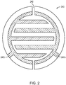
- FIG. 2 A representative configuration of the electrodes 240 is shown in FIG. 2 .
- the individual electrode elements 240a, 240b are interdigitated and may cover most of the floor of the elecrolysis chamber (for efficient use of limited space).
- the rendering is schematic and exemplary; the electrodes need not be interdigitated, and interdigitated electrodes need not conform to the simple illustrated pattern. In general, working embodiments will contain a greater number of interdigitations with less insulative surface area to optimize the efficiency of electrolysis gas generation and recombination and associated current and voltage requirements.
- the insulative region 242 maintains the necessary galvanic separation between the electrodes 240a, 240b, which have tabs that allow for convenient connection to lead wires electrically connecting the electrodes to the control circuitry.
- a single mask 250 covers an annular portion of the interdigitated electrode pair 240; due to electrode symmetry, a proportionally equivalent area of both electrodes 240a, 240b will be masked off.
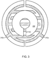
- FIG. 3 further shows that the single mask 250 that covers the annular portion of the interdigitated electrode pair 240 may optionally contain one or more alignment features 252. It is to be understood that various different electrode patterns create different axes of symmetry and that the mask shape, size, and quantity may be altered to accommodate the electrolysis gas recombination/generation ratio desired. That is, the ratio of masked to unmasked electrode regions may be chosen to achieve a target operating ratio of gas recombination to gas generation.
- the mask 250 is made of a solid, gas-impermeable material (e.g., a thermoplastic such as polyether ether ketone (PEEK) or a ceramic or other insulator) that is affixed to or deposited over the electrodes 240 to lower the recombination rate by reducing the exposed area of the electrodes in an electrolysis cell.
- a solid, gas-impermeable material e.g., a thermoplastic such as polyether ether ketone (PEEK) or a ceramic or other insulator
- PEEK polyether ether ketone
- the shape and surface area of the mask can be altered to tune electrolysis properties.
- the geometry of a round electrode may be revised into another shape (e.g., a square), or an electrode pair may be patterned (e.g., with interdigitating fingers) in order to comparatively test the effect of shape and configuration on performance.
- the most important design parameter for a mask from a functional perspective is the surface area of the mask relative to the surface area of the electrodes.
- the shape of the mask also has an effect on the ratio of the gas-recombination rate to the gas-generation rate.
- the illustrated mask 250 has a ring shape. Experimentation has shown that on a circular set of electrodes, a mask with the same surface area but no center hole did not yield the recombination/generation ratio desired. This was due to the way this cell operated- specifically, generated gas moved towards the center of the electrode area. With a mask shaped as a solid disk, recombination would occur slowly because, with increasing inward distance from the disk edge, a gas bubble has farther to travel before clearing the mask and reaching the outer electrodes. With a hole in the center of the mask, by contrast, a moderate amount of recombination occurs in the center, and no gas bubble has further to travel than the annular extent of the mask.
- the electrolysis mask is attached to the chip by an adhesive, e.g., an epoxy.
- an adhesive e.g., an epoxy.
- Suitable adhesives tolerate both electrolysis and recombination without excessive delamination, which may gradually modify the recombination/generation ratio as the mask fails over time.
- a rigid electrolysis mask material may be selected to minimize the delaminating effects of mechanical forces caused by the flexing of the electrolysis mask when electrolysis gas is generated.
- the electrolysis mask is deposited, e.g., through a patterned stencil template.
- materials such as silicon nitride can be deposited by chemical vapor deposition (CVD), though any deposition technique suited to the selected mask material can be used. With this approach, successive depositions can gradually widen the mask, with each deposition occupying an equivalent incremental area. The performance of the chip can be tested between depositions.
- the mask may be deposited by ink-jet or other pointwise deposition process in accordance with a digitally stored pattern.
- mask deposition can be used to fabricate finished production electrolysis chips in addition to chips used for experimental purposes.
- a basic template electrode pattern may be established for mass production, and this pattern may be tailored, using application-specific masks, to devices having different performance requirements. That is, masking may be used in the manufacture of finished devices in addition to its experimental use in defining an optimal electrode pattern for a particular chip.
- FIG. 4 shows an exploded schematic perspective view of the pump assembly.
- the recombination mask 250 overlies a portion of the electrodes (not shown in this figure) on the electrolysis chip 400.
- adhesive, deposition or other methods may be used to attach the electrolysis recombination mask 250 to the electrolysis chip 400.
- a spacer 410 may also be attached to the electrolysis chip 400 to accommodate the height of the electrolysis recombination mask 250 relative to overlying components.
- a force transducer 420 - i.e., an expandable membrane as described in connection with FIG. 1 - overlies the electrode chip 400.
- the space between the electrode chip 400 and the force transducer 420 constitutes the volume of the electrolysis chamber.
- the spacer 410 can be varied to achieve a target chamber volume and, therefore, the amount of electrolysis fluid in the chamber.
- the spacer 410 may contain openings (e.g. pass-throughs, holes, slots, etc.) into which electrolysis fluid fill tubes of a specific height may be integrated to facilitate electrolyte solution fill or addition.
- the spacer may integrate the mask and be affixed to the electrolysis cell as one component.
Landscapes
- Chemical & Material Sciences (AREA)
- Engineering & Computer Science (AREA)
- Health & Medical Sciences (AREA)
- Chemical Kinetics & Catalysis (AREA)
- Electrochemistry (AREA)
- Materials Engineering (AREA)
- Metallurgy (AREA)
- Organic Chemistry (AREA)
- Veterinary Medicine (AREA)
- Public Health (AREA)
- General Health & Medical Sciences (AREA)
- Vascular Medicine (AREA)
- Anesthesiology (AREA)
- Biomedical Technology (AREA)
- Heart & Thoracic Surgery (AREA)
- Hematology (AREA)
- Life Sciences & Earth Sciences (AREA)
- Animal Behavior & Ethology (AREA)
- Inorganic Chemistry (AREA)
- Fluid Mechanics (AREA)
- Physics & Mathematics (AREA)
- Ceramic Engineering (AREA)
- Electrolytic Production Of Non-Metals, Compounds, Apparatuses Therefor (AREA)
- Media Introduction/Drainage Providing Device (AREA)
- Physical Or Chemical Processes And Apparatus (AREA)
- Chemical Vapour Deposition (AREA)
- Infusion, Injection, And Reservoir Apparatuses (AREA)
- Electrodes For Compound Or Non-Metal Manufacture (AREA)
Claims (14)
- Vorrichtung (100) zum Verabreichen einer Flüssigkeit, wobei die Vorrichtung umfasst:ein Gehäuse (160);innerhalb des Gehäuses eine Pumpenbaugruppe mit einem Reservoir (130), einem elektrolytischen Druckmechanismus (140, 240) und einer Kanüle (120) zum Leiten von Flüssigkeit aus dem Reservoir zu einer Ausstoßstelle außerhalb des Gehäuses als Antwort auf durch den Druckmechanismus ausgeübten Druck; undinnerhalb des Druckmechanismus ein Elektrolytreservoir (140) und darin eine Elektrodenbaugruppe (240), die (i) mindestens zwei Elektroden (240a, 240b) und (ii) auf einem Abschnitt mindestens einer der Elektroden eine gasundurchlässige Maske (250) umfasst, worin die Maske so bemessen und geformt ist, dass ein Verhältnis von maskierten zu unmaskierten Elektrodenabschnitten ein Sollbetriebsverhältnis von Gasrekombination zu Gaserzeugung erzielt.
- Elektrolytische Pumpe nach Anspruch 1, worin die Elektroden (240a, 240b) auf einem Elektrolysechip (400) angeordnet sind.
- Elektrolytische Pumpe nach Anspruch 1, worin die Elektroden (240a, 240b) mindestens eines von Platin, Gold oder Silber auf Parylen, Keramik oder einem biologisch verträglichen Isolator umfassen.
- Elektrolytische Pumpe nach Anspruch 1, worin die Elektroden (240a, 240b) als Rekombinationskatalysator wirken und ferner einen zusätzlichen Rekombinationskatalysator umfassen.
- Vorrichtung nach Anspruch 1, worin mindestens ein Teil der Maskenstruktur (250) mit einem Epoxidharz auf die Elektroden geklebt ist.
- Vorrichtung nach Anspruch 1, worin die Struktur der Maske (250) PEEK, Keramik, Aluminium umfasst.
- Vorrichtung nach Anspruch 1, ferner umfassend einen Abstandshalter (410) mit einer Höhe, die eine Höhe des Elektrolytreservoirs (140) definiert.
- Vorrichtung nach Anspruch 7, worin der Abstandshalter (410) die Elektroden (240a, 240b) umgibt und nicht mit ihnen verklebt ist.
- Verfahren zum Herstellen einer Vorrichtung (100) zum Verabreichen einer Flüssigkeit, wobei die Vorrichtung umfasst: ein Gehäuse (160) und, innerhalb des Gehäuses, eine Pumpenbaugruppe mit einem Reservoir (130), einem gasbetriebenen Druckmechanismus (140, 240) und einer Kanüle (120) zum Leiten von Flüssigkeit aus dem Reservoir zu einer Ausstoßstelle außerhalb des Gehäuses als Antwort auf durch den Druckmechanismus ausgeübten Druck, und innerhalb des Druckmechanismus ein Elektrolytreservoir (140), wobei das Verfahren die Schritte umfasst:Bereitstellen von mindestens zwei Elektroden (240a, 240b);Maskieren eines Abschnitts von mindestens einer der Elektroden mit einem gasundurchlässigen Material (250); undEinführen der Elektroden (240a, 240b) in das Elektrolytreservoir (140), wodurch ein freiliegender Teil der Elektroden dafür strukturiert ist, ein Sollbetriebsverhältnis von Gasrekombination zu Gaserzeugung im Reservoir zu erzielen.
- Verfahren nach Anspruch 9, worin der Maskierungsschritt umfasst: Abscheiden des gasundurchlässigen Materials (250) auf mindestens einer der Elektroden (240a, 240b) durch eine Strukturschablone.
- Verfahren nach Anspruch 10, worin das gasundurchlässige Material (250) durch chemische Gasphasenabscheidung aufgebracht wird.
- Verfahren nach Anspruch 9, worin der Maskierungsschritt umfasst: Abscheiden des gasundurchlässigen Materials (250) auf mindestens einer der Elektroden (240a, 240b) durch punktweises Drucken in einer vorbestimmten Struktur.
- Verfahren nach Anspruch 9, worin der Maskierungsschritt umfasst: Ankleben eines gasundurchlässigen Materials (250) auf mindestens einer der Elektroden (240a, 240b).
- Verfahren nach Anspruch 9, ferner den Schritt umfassend: Einbauen eines Abstandshalters (410) auf einem Nicht-Elektrodenabschnitt des Elektrolytreservoirs (140).
Applications Claiming Priority (2)
| Application Number | Priority Date | Filing Date | Title |
|---|---|---|---|
| US201361839166P | 2013-06-25 | 2013-06-25 | |
| PCT/US2014/044106 WO2014210161A1 (en) | 2013-06-25 | 2014-06-25 | Electrolysis recombination control mask and method of manufacture thereof |
Publications (2)
| Publication Number | Publication Date |
|---|---|
| EP3013391A1 EP3013391A1 (de) | 2016-05-04 |
| EP3013391B1 true EP3013391B1 (de) | 2018-10-24 |
Family
ID=51257573
Family Applications (1)
| Application Number | Title | Priority Date | Filing Date |
|---|---|---|---|
| EP14744993.8A Not-in-force EP3013391B1 (de) | 2013-06-25 | 2014-06-25 | Elektrolyserekombinationssteuerungsmaske und verfahren zur herstellung davon |
Country Status (7)
| Country | Link |
|---|---|
| US (1) | US20140374245A1 (de) |
| EP (1) | EP3013391B1 (de) |
| JP (1) | JP2016529948A (de) |
| CN (1) | CN105431187A (de) |
| AU (1) | AU2014302460A1 (de) |
| CA (1) | CA2915985A1 (de) |
| WO (1) | WO2014210161A1 (de) |
Families Citing this family (5)
| Publication number | Priority date | Publication date | Assignee | Title |
|---|---|---|---|---|
| WO2018072677A1 (en) * | 2016-10-17 | 2018-04-26 | MicroMED Co., Ltd. | Micro delivery device |
| US11460020B2 (en) * | 2019-02-19 | 2022-10-04 | MicroMED Co., Ltd. | Micro-delivery device |
| CN115867726A (zh) * | 2020-07-07 | 2023-03-28 | 康迈德有限公司 | 电化学致动器和致动器阵列 |
| TWI806182B (zh) * | 2020-11-18 | 2023-06-21 | 潔霺生醫科技股份有限公司 | 多段式氣體致動供藥裝置及方法 |
| CN116059530A (zh) * | 2021-11-02 | 2023-05-05 | 洁霺生医科技股份有限公司 | 用于药剂递送的电化学泵及其药剂递送装置 |
Family Cites Families (8)
| Publication number | Priority date | Publication date | Assignee | Title |
|---|---|---|---|---|
| DK0746356T3 (da) * | 1991-10-24 | 2000-10-02 | Macromed Inc | Gasdrevet anordning til indgivelse af medikamenter |
| IE70735B1 (en) * | 1994-08-15 | 1996-12-11 | Elan Med Tech | Orally administrable delivery device |
| DE19756775A1 (de) * | 1997-08-01 | 1999-02-04 | Arithmed Gmbh Medizinische Mes | Tragbarer Medikamentenspender zur zeitverzögerten Verabreichung von Injektions- oder Infusionspräparaten |
| US7427341B2 (en) * | 2003-08-15 | 2008-09-23 | Symyx Technologies, Inc. | System for synthesis of electrode array |
| EP2319558B1 (de) * | 2006-03-14 | 2014-05-21 | University Of Southern California | Mems-Vorrichtung zur Wirkstofffreisetzung |
| EP2320989B1 (de) * | 2008-05-08 | 2015-03-11 | MiniPumps, LLC | Implantierbare pumpen und kanülen dafür |
| EP2467797B1 (de) * | 2009-08-18 | 2017-07-19 | MiniPumps, LLC | Elektrolytische arzneimittelverabreichungspumpe mit adaptiver steuerung |
| CN103108665A (zh) * | 2010-04-20 | 2013-05-15 | 迷你泵有限责任公司 | 电解驱动药物泵装置 |
-
2014
- 2014-06-25 EP EP14744993.8A patent/EP3013391B1/de not_active Not-in-force
- 2014-06-25 WO PCT/US2014/044106 patent/WO2014210161A1/en not_active Ceased
- 2014-06-25 US US14/314,869 patent/US20140374245A1/en not_active Abandoned
- 2014-06-25 CA CA2915985A patent/CA2915985A1/en not_active Abandoned
- 2014-06-25 CN CN201480036211.9A patent/CN105431187A/zh active Pending
- 2014-06-25 AU AU2014302460A patent/AU2014302460A1/en not_active Abandoned
- 2014-06-25 JP JP2016521911A patent/JP2016529948A/ja active Pending
Non-Patent Citations (1)
| Title |
|---|
| None * |
Also Published As
| Publication number | Publication date |
|---|---|
| CN105431187A (zh) | 2016-03-23 |
| EP3013391A1 (de) | 2016-05-04 |
| US20140374245A1 (en) | 2014-12-25 |
| JP2016529948A (ja) | 2016-09-29 |
| CA2915985A1 (en) | 2014-12-31 |
| WO2014210161A1 (en) | 2014-12-31 |
| AU2014302460A1 (en) | 2016-01-21 |
Similar Documents
| Publication | Publication Date | Title |
|---|---|---|
| EP3013391B1 (de) | Elektrolyserekombinationssteuerungsmaske und verfahren zur herstellung davon | |
| EP3030286B1 (de) | Anschmiegbare patch pumpe | |
| EP2319558B1 (de) | Mems-Vorrichtung zur Wirkstofffreisetzung | |
| US10881786B2 (en) | Wearable liquid supplying device for human insulin injection | |
| US20030014014A1 (en) | Drug delivery device and method | |
| US9107995B2 (en) | Drug-delivery pumps and methods of manufacture | |
| US20160206811A1 (en) | Implantable Electrolytic Diaphragm Pumps | |
| EP2717944B1 (de) | Implantierbare vorrichtung mit anpassbarer telemetriespule und herstellungsverfahren dafür | |
| Gensler et al. | Implantable MEMS drug delivery device for cancer radiation reduction | |
| US20160089490A1 (en) | Drug delivery device including electrolytic pump |
Legal Events
| Date | Code | Title | Description |
|---|---|---|---|
| PUAI | Public reference made under article 153(3) epc to a published international application that has entered the european phase |
Free format text: ORIGINAL CODE: 0009012 |
|
| 17P | Request for examination filed |
Effective date: 20160104 |
|
| AK | Designated contracting states |
Kind code of ref document: A1 Designated state(s): AL AT BE BG CH CY CZ DE DK EE ES FI FR GB GR HR HU IE IS IT LI LT LU LV MC MK MT NL NO PL PT RO RS SE SI SK SM TR |
|
| AX | Request for extension of the european patent |
Extension state: BA ME |
|
| DAX | Request for extension of the european patent (deleted) | ||
| RIC1 | Information provided on ipc code assigned before grant |
Ipc: C25B 1/04 20060101ALI20180323BHEP Ipc: C25B 11/04 20060101ALI20180323BHEP Ipc: A61M 5/168 20060101AFI20180323BHEP Ipc: A61M 5/145 20060101ALI20180323BHEP Ipc: C25B 15/08 20060101ALI20180323BHEP Ipc: A61M 5/142 20060101ALI20180323BHEP |
|
| GRAP | Despatch of communication of intention to grant a patent |
Free format text: ORIGINAL CODE: EPIDOSNIGR1 |
|
| STAA | Information on the status of an ep patent application or granted ep patent |
Free format text: STATUS: GRANT OF PATENT IS INTENDED |
|
| INTG | Intention to grant announced |
Effective date: 20180507 |
|
| GRAS | Grant fee paid |
Free format text: ORIGINAL CODE: EPIDOSNIGR3 |
|
| GRAA | (expected) grant |
Free format text: ORIGINAL CODE: 0009210 |
|
| STAA | Information on the status of an ep patent application or granted ep patent |
Free format text: STATUS: THE PATENT HAS BEEN GRANTED |
|
| AK | Designated contracting states |
Kind code of ref document: B1 Designated state(s): AL AT BE BG CH CY CZ DE DK EE ES FI FR GB GR HR HU IE IS IT LI LT LU LV MC MK MT NL NO PL PT RO RS SE SI SK SM TR |
|
| REG | Reference to a national code |
Ref country code: CH Ref legal event code: EP |
|
| REG | Reference to a national code |
Ref country code: IE Ref legal event code: FG4D |
|
| REG | Reference to a national code |
Ref country code: AT Ref legal event code: REF Ref document number: 1055939 Country of ref document: AT Kind code of ref document: T Effective date: 20181115 |
|
| REG | Reference to a national code |
Ref country code: DE Ref legal event code: R096 Ref document number: 602014034653 Country of ref document: DE |
|
| REG | Reference to a national code |
Ref country code: CH Ref legal event code: NV Representative=s name: SERVOPATENT GMBH, CH |
|
| REG | Reference to a national code |
Ref country code: NL Ref legal event code: MP Effective date: 20181024 |
|
| REG | Reference to a national code |
Ref country code: LT Ref legal event code: MG4D |
|
| REG | Reference to a national code |
Ref country code: AT Ref legal event code: MK05 Ref document number: 1055939 Country of ref document: AT Kind code of ref document: T Effective date: 20181024 |
|
| PG25 | Lapsed in a contracting state [announced via postgrant information from national office to epo] |
Ref country code: NL Free format text: LAPSE BECAUSE OF FAILURE TO SUBMIT A TRANSLATION OF THE DESCRIPTION OR TO PAY THE FEE WITHIN THE PRESCRIBED TIME-LIMIT Effective date: 20181024 |
|
| PG25 | Lapsed in a contracting state [announced via postgrant information from national office to epo] |
Ref country code: FI Free format text: LAPSE BECAUSE OF FAILURE TO SUBMIT A TRANSLATION OF THE DESCRIPTION OR TO PAY THE FEE WITHIN THE PRESCRIBED TIME-LIMIT Effective date: 20181024 Ref country code: LV Free format text: LAPSE BECAUSE OF FAILURE TO SUBMIT A TRANSLATION OF THE DESCRIPTION OR TO PAY THE FEE WITHIN THE PRESCRIBED TIME-LIMIT Effective date: 20181024 Ref country code: HR Free format text: LAPSE BECAUSE OF FAILURE TO SUBMIT A TRANSLATION OF THE DESCRIPTION OR TO PAY THE FEE WITHIN THE PRESCRIBED TIME-LIMIT Effective date: 20181024 Ref country code: PL Free format text: LAPSE BECAUSE OF FAILURE TO SUBMIT A TRANSLATION OF THE DESCRIPTION OR TO PAY THE FEE WITHIN THE PRESCRIBED TIME-LIMIT Effective date: 20181024 Ref country code: LT Free format text: LAPSE BECAUSE OF FAILURE TO SUBMIT A TRANSLATION OF THE DESCRIPTION OR TO PAY THE FEE WITHIN THE PRESCRIBED TIME-LIMIT Effective date: 20181024 Ref country code: AT Free format text: LAPSE BECAUSE OF FAILURE TO SUBMIT A TRANSLATION OF THE DESCRIPTION OR TO PAY THE FEE WITHIN THE PRESCRIBED TIME-LIMIT Effective date: 20181024 Ref country code: BG Free format text: LAPSE BECAUSE OF FAILURE TO SUBMIT A TRANSLATION OF THE DESCRIPTION OR TO PAY THE FEE WITHIN THE PRESCRIBED TIME-LIMIT Effective date: 20190124 Ref country code: ES Free format text: LAPSE BECAUSE OF FAILURE TO SUBMIT A TRANSLATION OF THE DESCRIPTION OR TO PAY THE FEE WITHIN THE PRESCRIBED TIME-LIMIT Effective date: 20181024 Ref country code: IS Free format text: LAPSE BECAUSE OF FAILURE TO SUBMIT A TRANSLATION OF THE DESCRIPTION OR TO PAY THE FEE WITHIN THE PRESCRIBED TIME-LIMIT Effective date: 20190224 Ref country code: NO Free format text: LAPSE BECAUSE OF FAILURE TO SUBMIT A TRANSLATION OF THE DESCRIPTION OR TO PAY THE FEE WITHIN THE PRESCRIBED TIME-LIMIT Effective date: 20190124 |
|
| PG25 | Lapsed in a contracting state [announced via postgrant information from national office to epo] |
Ref country code: PT Free format text: LAPSE BECAUSE OF FAILURE TO SUBMIT A TRANSLATION OF THE DESCRIPTION OR TO PAY THE FEE WITHIN THE PRESCRIBED TIME-LIMIT Effective date: 20190224 Ref country code: GR Free format text: LAPSE BECAUSE OF FAILURE TO SUBMIT A TRANSLATION OF THE DESCRIPTION OR TO PAY THE FEE WITHIN THE PRESCRIBED TIME-LIMIT Effective date: 20190125 Ref country code: RS Free format text: LAPSE BECAUSE OF FAILURE TO SUBMIT A TRANSLATION OF THE DESCRIPTION OR TO PAY THE FEE WITHIN THE PRESCRIBED TIME-LIMIT Effective date: 20181024 Ref country code: SE Free format text: LAPSE BECAUSE OF FAILURE TO SUBMIT A TRANSLATION OF THE DESCRIPTION OR TO PAY THE FEE WITHIN THE PRESCRIBED TIME-LIMIT Effective date: 20181024 Ref country code: AL Free format text: LAPSE BECAUSE OF FAILURE TO SUBMIT A TRANSLATION OF THE DESCRIPTION OR TO PAY THE FEE WITHIN THE PRESCRIBED TIME-LIMIT Effective date: 20181024 |
|
| REG | Reference to a national code |
Ref country code: DE Ref legal event code: R097 Ref document number: 602014034653 Country of ref document: DE |
|
| PG25 | Lapsed in a contracting state [announced via postgrant information from national office to epo] |
Ref country code: IT Free format text: LAPSE BECAUSE OF FAILURE TO SUBMIT A TRANSLATION OF THE DESCRIPTION OR TO PAY THE FEE WITHIN THE PRESCRIBED TIME-LIMIT Effective date: 20181024 Ref country code: CZ Free format text: LAPSE BECAUSE OF FAILURE TO SUBMIT A TRANSLATION OF THE DESCRIPTION OR TO PAY THE FEE WITHIN THE PRESCRIBED TIME-LIMIT Effective date: 20181024 Ref country code: DK Free format text: LAPSE BECAUSE OF FAILURE TO SUBMIT A TRANSLATION OF THE DESCRIPTION OR TO PAY THE FEE WITHIN THE PRESCRIBED TIME-LIMIT Effective date: 20181024 |
|
| PG25 | Lapsed in a contracting state [announced via postgrant information from national office to epo] |
Ref country code: SM Free format text: LAPSE BECAUSE OF FAILURE TO SUBMIT A TRANSLATION OF THE DESCRIPTION OR TO PAY THE FEE WITHIN THE PRESCRIBED TIME-LIMIT Effective date: 20181024 Ref country code: EE Free format text: LAPSE BECAUSE OF FAILURE TO SUBMIT A TRANSLATION OF THE DESCRIPTION OR TO PAY THE FEE WITHIN THE PRESCRIBED TIME-LIMIT Effective date: 20181024 Ref country code: SK Free format text: LAPSE BECAUSE OF FAILURE TO SUBMIT A TRANSLATION OF THE DESCRIPTION OR TO PAY THE FEE WITHIN THE PRESCRIBED TIME-LIMIT Effective date: 20181024 Ref country code: RO Free format text: LAPSE BECAUSE OF FAILURE TO SUBMIT A TRANSLATION OF THE DESCRIPTION OR TO PAY THE FEE WITHIN THE PRESCRIBED TIME-LIMIT Effective date: 20181024 |
|
| PLBE | No opposition filed within time limit |
Free format text: ORIGINAL CODE: 0009261 |
|
| STAA | Information on the status of an ep patent application or granted ep patent |
Free format text: STATUS: NO OPPOSITION FILED WITHIN TIME LIMIT |
|
| 26N | No opposition filed |
Effective date: 20190725 |
|
| PG25 | Lapsed in a contracting state [announced via postgrant information from national office to epo] |
Ref country code: SI Free format text: LAPSE BECAUSE OF FAILURE TO SUBMIT A TRANSLATION OF THE DESCRIPTION OR TO PAY THE FEE WITHIN THE PRESCRIBED TIME-LIMIT Effective date: 20181024 |
|
| PG25 | Lapsed in a contracting state [announced via postgrant information from national office to epo] |
Ref country code: MC Free format text: LAPSE BECAUSE OF FAILURE TO SUBMIT A TRANSLATION OF THE DESCRIPTION OR TO PAY THE FEE WITHIN THE PRESCRIBED TIME-LIMIT Effective date: 20181024 |
|
| PGFP | Annual fee paid to national office [announced via postgrant information from national office to epo] |
Ref country code: FR Payment date: 20191120 Year of fee payment: 7 |
|
| REG | Reference to a national code |
Ref country code: BE Ref legal event code: MM Effective date: 20190630 |
|
| PG25 | Lapsed in a contracting state [announced via postgrant information from national office to epo] |
Ref country code: TR Free format text: LAPSE BECAUSE OF FAILURE TO SUBMIT A TRANSLATION OF THE DESCRIPTION OR TO PAY THE FEE WITHIN THE PRESCRIBED TIME-LIMIT Effective date: 20181024 |
|
| PG25 | Lapsed in a contracting state [announced via postgrant information from national office to epo] |
Ref country code: IE Free format text: LAPSE BECAUSE OF NON-PAYMENT OF DUE FEES Effective date: 20190625 |
|
| PG25 | Lapsed in a contracting state [announced via postgrant information from national office to epo] |
Ref country code: BE Free format text: LAPSE BECAUSE OF NON-PAYMENT OF DUE FEES Effective date: 20190630 Ref country code: LU Free format text: LAPSE BECAUSE OF NON-PAYMENT OF DUE FEES Effective date: 20190625 |
|
| REG | Reference to a national code |
Ref country code: CH Ref legal event code: PCAR Free format text: NEW ADDRESS: WANNERSTRASSE 9/1, 8045 ZUERICH (CH) |
|
| PGFP | Annual fee paid to national office [announced via postgrant information from national office to epo] |
Ref country code: CH Payment date: 20200618 Year of fee payment: 7 Ref country code: DE Payment date: 20200618 Year of fee payment: 7 |
|
| PGFP | Annual fee paid to national office [announced via postgrant information from national office to epo] |
Ref country code: GB Payment date: 20200625 Year of fee payment: 7 |
|
| PG25 | Lapsed in a contracting state [announced via postgrant information from national office to epo] |
Ref country code: CY Free format text: LAPSE BECAUSE OF FAILURE TO SUBMIT A TRANSLATION OF THE DESCRIPTION OR TO PAY THE FEE WITHIN THE PRESCRIBED TIME-LIMIT Effective date: 20181024 |
|
| PG25 | Lapsed in a contracting state [announced via postgrant information from national office to epo] |
Ref country code: HU Free format text: LAPSE BECAUSE OF FAILURE TO SUBMIT A TRANSLATION OF THE DESCRIPTION OR TO PAY THE FEE WITHIN THE PRESCRIBED TIME-LIMIT; INVALID AB INITIO Effective date: 20140625 Ref country code: MT Free format text: LAPSE BECAUSE OF FAILURE TO SUBMIT A TRANSLATION OF THE DESCRIPTION OR TO PAY THE FEE WITHIN THE PRESCRIBED TIME-LIMIT Effective date: 20181024 |
|
| REG | Reference to a national code |
Ref country code: DE Ref legal event code: R119 Ref document number: 602014034653 Country of ref document: DE |
|
| REG | Reference to a national code |
Ref country code: CH Ref legal event code: PL |
|
| GBPC | Gb: european patent ceased through non-payment of renewal fee |
Effective date: 20210625 |
|
| PG25 | Lapsed in a contracting state [announced via postgrant information from national office to epo] |
Ref country code: LI Free format text: LAPSE BECAUSE OF NON-PAYMENT OF DUE FEES Effective date: 20210630 Ref country code: GB Free format text: LAPSE BECAUSE OF NON-PAYMENT OF DUE FEES Effective date: 20210625 Ref country code: DE Free format text: LAPSE BECAUSE OF NON-PAYMENT OF DUE FEES Effective date: 20220101 Ref country code: CH Free format text: LAPSE BECAUSE OF NON-PAYMENT OF DUE FEES Effective date: 20210630 |
|
| PG25 | Lapsed in a contracting state [announced via postgrant information from national office to epo] |
Ref country code: FR Free format text: LAPSE BECAUSE OF NON-PAYMENT OF DUE FEES Effective date: 20210630 |
|
| PG25 | Lapsed in a contracting state [announced via postgrant information from national office to epo] |
Ref country code: MK Free format text: LAPSE BECAUSE OF FAILURE TO SUBMIT A TRANSLATION OF THE DESCRIPTION OR TO PAY THE FEE WITHIN THE PRESCRIBED TIME-LIMIT Effective date: 20181024 |
|
| P01 | Opt-out of the competence of the unified patent court (upc) registered |
Effective date: 20230527 |