EP3013093B1 - Dispositif de terminal, circuit intégré et procédé de communication sans fil - Google Patents
Dispositif de terminal, circuit intégré et procédé de communication sans fil Download PDFInfo
- Publication number
- EP3013093B1 EP3013093B1 EP14814290.4A EP14814290A EP3013093B1 EP 3013093 B1 EP3013093 B1 EP 3013093B1 EP 14814290 A EP14814290 A EP 14814290A EP 3013093 B1 EP3013093 B1 EP 3013093B1
- Authority
- EP
- European Patent Office
- Prior art keywords
- subframe
- uplink
- downlink
- configuration
- station device
- Prior art date
- Legal status (The legal status is an assumption and is not a legal conclusion. Google has not performed a legal analysis and makes no representation as to the accuracy of the status listed.)
- Active
Links
Images


Classifications
-
- H—ELECTRICITY
- H04—ELECTRIC COMMUNICATION TECHNIQUE
- H04L—TRANSMISSION OF DIGITAL INFORMATION, e.g. TELEGRAPHIC COMMUNICATION
- H04L5/00—Arrangements affording multiple use of the transmission path
- H04L5/003—Arrangements for allocating sub-channels of the transmission path
- H04L5/0048—Allocation of pilot signals, i.e. of signals known to the receiver
-
- H—ELECTRICITY
- H04—ELECTRIC COMMUNICATION TECHNIQUE
- H04L—TRANSMISSION OF DIGITAL INFORMATION, e.g. TELEGRAPHIC COMMUNICATION
- H04L5/00—Arrangements affording multiple use of the transmission path
- H04L5/003—Arrangements for allocating sub-channels of the transmission path
- H04L5/0053—Allocation of signaling, i.e. of overhead other than pilot signals
- H04L5/0057—Physical resource allocation for CQI
-
- H—ELECTRICITY
- H04—ELECTRIC COMMUNICATION TECHNIQUE
- H04L—TRANSMISSION OF DIGITAL INFORMATION, e.g. TELEGRAPHIC COMMUNICATION
- H04L5/00—Arrangements affording multiple use of the transmission path
- H04L5/0091—Signaling for the administration of the divided path
- H04L5/0092—Indication of how the channel is divided
-
- H—ELECTRICITY
- H04—ELECTRIC COMMUNICATION TECHNIQUE
- H04L—TRANSMISSION OF DIGITAL INFORMATION, e.g. TELEGRAPHIC COMMUNICATION
- H04L5/00—Arrangements affording multiple use of the transmission path
- H04L5/14—Two-way operation using the same type of signal, i.e. duplex
- H04L5/1469—Two-way operation using the same type of signal, i.e. duplex using time-sharing
-
- H—ELECTRICITY
- H04—ELECTRIC COMMUNICATION TECHNIQUE
- H04W—WIRELESS COMMUNICATION NETWORKS
- H04W24/00—Supervisory, monitoring or testing arrangements
- H04W24/10—Scheduling measurement reports ; Arrangements for measurement reports
-
- H—ELECTRICITY
- H04—ELECTRIC COMMUNICATION TECHNIQUE
- H04W—WIRELESS COMMUNICATION NETWORKS
- H04W72/00—Local resource management
- H04W72/04—Wireless resource allocation
- H04W72/044—Wireless resource allocation based on the type of the allocated resource
- H04W72/0446—Resources in time domain, e.g. slots or frames
-
- H—ELECTRICITY
- H04—ELECTRIC COMMUNICATION TECHNIQUE
- H04L—TRANSMISSION OF DIGITAL INFORMATION, e.g. TELEGRAPHIC COMMUNICATION
- H04L5/00—Arrangements affording multiple use of the transmission path
- H04L5/0001—Arrangements for dividing the transmission path
- H04L5/0003—Two-dimensional division
- H04L5/0005—Time-frequency
- H04L5/0007—Time-frequency the frequencies being orthogonal, e.g. OFDM(A), DMT
- H04L5/001—Time-frequency the frequencies being orthogonal, e.g. OFDM(A), DMT the frequencies being arranged in component carriers
-
- H—ELECTRICITY
- H04—ELECTRIC COMMUNICATION TECHNIQUE
- H04L—TRANSMISSION OF DIGITAL INFORMATION, e.g. TELEGRAPHIC COMMUNICATION
- H04L5/00—Arrangements affording multiple use of the transmission path
- H04L5/0001—Arrangements for dividing the transmission path
- H04L5/0014—Three-dimensional division
- H04L5/0023—Time-frequency-space
Definitions
- the present invention relates to a terminal device, a base station device, an integrated circuit, and a wireless communication method.
- LTE Long Term Evolution
- EUTRA Evolved Universal Terrestrial Radio Access
- a base station device is also referred to as an evolved NodeB (eNodeB) and a mobile station device is referred to as user equipment (UE).
- eNodeB evolved NodeB
- UE user equipment
- LTE is a cellular communication system in which an area is divided in a cellular pattern into multiple cells, each being served by a base station device. A single base station device may manage multiple cells.
- LTE supports Time Division Duplex (TDD).
- TDD Time Division Duplex
- LTE that employs a TDD scheme is also referred to as TD-LTE or LTE TDD.
- TDD is a technology that enables full duplex communication in a single frequency band by performing time division multiplexing on an uplink signal and a downlink signal.
- the traffic adaptation technology is a technology that changes a ratio of an uplink resource to a downlink resource according to uplink traffic and downlink traffic.
- the traffic adaptation technology is also referred to as dynamic TDD.
- NPL 1 a method of using a flexible subframe is disclosed as a method of realizing traffic adaptation.
- the base station device can perform reception of the uplink signal or transmission of the downlink signal on the flexible subframe.
- the mobile station device regards the flexible subframe as the downlink subframe.
- hybrid automatic repeat request (HARQ) timing for a PDSCH (physical downlink shared channel) is determined based on newly introduced uplink-downlink configuration, and the HARQ timing for a physical uplink shared channel (PUSCH) is determined based on the first UL-DL configuration.
- HARQ hybrid automatic repeat request
- NPL 2 it is disclosed that (a) a UL/DL reference configuration is introduced and that (b) several subframes are scheduled, for either of uplink and downlink, by dynamic grant/assignment from a scheduler.
- a procedure that is performed by the mobile station device for reporting of channel state information is disclosed.
- the base station device allocates a downlink resource to the mobile station device, based on the channel state information that is reported from multiple mobile station devices.
- the channel state information includes a channel quality indicator (CQI).
- CSI reference subframe for half duplex TDD UE by ASUTek (3GPP Draft; R1-131041 CSI reference subframe for half duplex TDD UE, 20130406 3rd Generation Partnership Project (3GPP), Mobile Competence Centre; 650, route des Lucioles; F-06921 Sophia-Antipolis Cedex; France; Vol:RAN WG1, Nr:Chicago, USA; 20130415 - 20130419 ) discusses the issue that a UE may choose a subframe where the UE cannot receive any signal as a CSI reference resource and proposes to modify the valid downlink subframe definition for TDD half-duplex UEs.
- 3GPP 3rd Generation Partnership Project
- An object of the present invention which is made in view of the problem described above, is to provide a terminal device, an integrated circuit, and a wireless communication method, in each of which communication can efficiently be performed in a wireless communication system in which channel station information is used.
- a mobile station device and a base station device can efficiently communicate with each other.
- multiple cells are set for a mobile station device.
- a technology in which a mobile station device performs communication with the multiple cells is referred to as a cell aggregation or a carrier aggregation.
- the present invention may be applied to each of the multiple cells that are set for the mobile station device. Furthermore, the present invention may be applied to some of the multiple cells that are set.
- a cell that is set for the mobile station device is also referred to as a serving cell.
- Multiple serving cells that are set include one primary cell or one or multiple secondary cells.
- the primary cell is a serving cell in which an initial connection establishment procedure is performed, a serving cell in which a connection re-establishment procedure is started, or a cell that is indicated as a primary cell during a handover procedure.
- a secondary cell may be set.
- a Time Division Duplex (TDD) scheme is applied to a wireless communication system according to the present embodiment.
- the TDD scheme may be applied to all multiple cells.
- a cell to which the TDD scheme is applied and a cell to which a Frequency Division Duplex (FDD) scheme is applied may be aggregated.
- the present invention can be applied to the cell to which the TDD is applied.
- a half-duplex TDD scheme or a full-duplex TDD scheme is applied.
- the mobile station device does not perform transmission and reception at the same time in one primary cell in a certain band or in one primary cell and one or multiple secondary cells in multiple different bands.
- the uplink transmission and the downlink reception can be performed at the same time in the multiple cells to each of which the TDD is applied.
- the mobile station device can perform the transmission and the reception at the same time in multiple serving cells in multiple different bands.
- the mobile station device transmits information showing a combination of bands in which the carrier aggregation is supported by the mobile station device, to the base station device. For each of the combinations of bands, the mobile station device transmits information indicating whether or not the transmission and the reception are supported at the same time in the multiple serving cells in the multiple different bands, to the base station device.
- X/Y includes the meaning of “X or Y”. According to the present embodiment, “X/Y” includes the meaning of “X and Y”. According to the present embodiment, “X/Y” includes the meaning of "X and/or Y”.
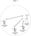
- Fig. 1 is a conceptual diagram of the wireless communication system according to the present embodiment.
- the wireless communication system includes mobile station devices 1A to 1C and a base station device 3.
- the mobile station devices 1A to 1C each are hereinafter referred to as a mobile station device 1.
- a physical channel and a physical signal according to the present embodiment are described.
- Fig. 1 in uplink wireless communication from the mobile station device 1 to the base station device 3, the following uplink physical channels are used.
- the uplink physical channel is used to transmit information that is output from a higher layer.
- Physical uplink control channel PUCCH
- PUSCH Physical uplink shared channel
- PRACH Physical random access channel
- the PUCCH is a physical channel that is used to transmit uplink control information (UCI)
- the pieces of uplink control information include downlink channel state information (CSI), a scheduling request (SR) showing a request for a PUSCH resource, and an acknowledgement (ACK)/negative-acknowledgement (NACK) of downlink data (a transport block or a downlink-shared channel (DL-SCH).
- CSI downlink channel state information
- SR scheduling request
- NACK acknowledgement/negative-acknowledgement
- the ACK/NACK is also referred to as a HARQ-ACK or HARQ feedback, or response information.
- the PUSCH is a physical channel that is used to transmit uplink data (uplink-shared channel (UL-SCH)). Furthermore, the PUSCH may be used to the HARQ-ACK and/or channel state information along with the uplink data. Furthermore, the PUSCH may be used to transmit only the channel state information or to transmit only the HARQ-ACK and the channel state information.
- uplink-shared channel UL-SCH
- the PRACH is a physical channel that is used to transmit to a random access preamble.
- a main object of the PRACH is to synchronize the mobile station device 1 to the base station device 3 in terms of a time domain.
- the PRACH is also used to show the initial connection establishment procedure, the handover procedure, the connection re-establishment procedure, synchronization (timing adjustment) for uplink transmission, and the request for the PUSCH resource.
- uplink physical signals are used for the uplink wireless communication.
- the uplink physical signal is not used to transmit information that is output from the higher layer, but is used by a physical layer.
- Uplink reference signal (UL RS) UL RS
- DMRS Demodulation reference signal
- SRS Sounding reference signal
- the DMRS relates to transmission of the PUSCH or the PUCCH.
- the DMRS is time-multiplexed along with the PUSCH or the PUCCH.
- the base station device 3 uses the DMRS in order to perform channel reconfiguration of the PUSCH or the PUCCH. Transmission of both of the PUSCH and the DMRS is hereinafter referred to simply as transmission of the PUSCH. Transmission of both of the PUCCH and the DMRS is hereinafter referred to as transmission of the PUCCH.
- the SRS has no relationship with the transmission of the PUSCH or the PUCCH.
- the base station device 3 uses the SRS in order to measure an uplink channel state.
- the mobile station device 1 transmits a first SRS in a first resource that is set by the higher layer. Additionally, in a case where information showing a request for transmission of the SRS is received through the PDCCH, the mobile station device 1 transmits a second SRS only one time in a second resource that is set by the higher layer.
- the first SRS is also referred to as a periodic SRS or a type 0 trigger SRS.
- the second SRS is also referred to as an aperiodic SRS or a type 1 trigger SRS. Transmission of the aperiodic SRS is scheduled by the information showing that the transmission of the SRS is requested.
- Fig. 1 the following downlink physical channels are used for downlink wireless communication from the base station device 3 to the mobile station device 1.
- the downlink physical channel is used to transmit the information that is output from the higher layer.
- Physical broadcast channel PBCH
- PCFICH Physical control format indicator channel
- PHICH Physical hybrid automatic repeat request indicator channel
- PDCCH Physical downlink control channel
- EPDCCH Enhanced physical downlink control channel
- PDSCH Physical downlink shared channel
- PMCH Physical multicast channel
- the PBCH is used to broadcast a master information block (MIB) (or a broadcast channel (BCH)) that is in common use in the mobile station device 1.
- MIB master information block
- BCH broadcast channel
- a system frame number (SFN) is a radio frame number.
- the MIB is system information. For example, the MIB includes information showing the SFN.
- the PCFICH is used to transmit information that indicates a region (an OFDM symbol) which is used for transmission of the PDCCH.
- the PHICH is used to transmit a HARQ indicator (the HARQ feedback or the response information) that shows an acknowledgement (ACK) of or a negative acknowledgement (NACK) of the uplink data (uplink shared channel (UL-SCH)) which is received by the base station device 3.
- a HARQ indicator the HARQ feedback or the response information
- ACK acknowledgement
- NACK negative acknowledgement
- uplink data uplink shared channel
- HARQ indicator for a single piece of uplink data is transmitted on a single PHICH.
- the base station device 3 transmits HARQ indicators for multiple pieces of uplink data that are included in the same PUSCH, using multiple PHICH, respectively.
- the PDCCH and the EPDCCH are used to transmit downlink control information (DCI).
- DCI downlink control information
- the downlink control information is also referred to as a DCI format.
- the downlink control information includes a downlink grant and an uplink grant.
- the downlink grant is also referred to as downlink assignment or downlink allocation.
- the downlink grant is used for scheduling of the PDSCH within a single cell.
- the downlink grant is used for the scheduling of the PDSCH within in the same subframe as the subframe on which the downlink grant is transmitted.
- the uplink grant is used for scheduling of the PUSCH within a single cell.
- the uplink grant is used for the scheduling of a single PUSCH within the fourth or later subframe after the subframe on which the uplink grant is transmitted.
- a cyclic redundancy check (CRC) parity bit is added to the DCI format.
- the CRC parity bit is scrambled with a cell-radio network temporary identifier (C-RNTI) or a semi persistent scheduling cell-radio network temporary identifier (SPS C-RNTI).
- C-RNTI cell-radio network temporary identifier
- SPS C-RNTI semi persistent scheduling cell-radio network temporary identifier
- the C-RNTI is used to control the PDSCH or the PUSCH in a single subframe.
- the SPS C-RNTI is used to periodically allocate a resource for the PDSCH or the PUSCH.
- the PDSCH is used for transmitting downlink data (downlink shared channel (DL-SCH)).
- DL-SCH downlink shared channel
- the PMCH is used to transmit a multicast channel (MCH).
- MCH multicast channel
- the following downlink physical signals are used.
- the downlink physical signal is not used to transmit the information that is output from the higher layer, but is used by the physical layer.
- Synchronization signal (SS) Downlink reference signal (DL RS)
- the synchronization signal is used in order for the mobile station device 1 to be synchronized in terms of frequency and time domains for downlink.
- the synchronization signal is mapped to subframes 0, 1, 5, and 6 within a radio frame.
- the synchronization signal is mapped to subframes 0 and 5 within the radio frame.
- the downlink reference signal is used in order for the mobile station device 1 to perform the channel reconfiguration of the downlink physical channel.
- the downlink reference signal is used in order for the mobile station device 1 to calculate the downlink channel state information.
- CRS Cell-specific reference signal
- URS UE-specific reference signal
- DMRS Demodulation reference signal
- NZP CSI-RS Non-zero power channel state information - reference signal
- ZP CSI - RS Zero power channel state information - reference signal
- MMSFN RS Multimedia broadcast and multicast service over single frequency network reference signal
- PRS Positioning reference signal
- the CRS is transmitted in an entire band for a subframe.
- the CRS is used to perform demodulation of the PBCH/PDCCH/PHICH/PCFICH/PDSCH.
- the CRS may be used in order for the mobile station device 1 to calculate the downlink channel state information.
- the PBCH/PDCCH/PHICH/PCFICH is transmitted in an antenna port that is used for transmission of the CRS.
- the URS relating to the PDSCH is transmitted on a subframe and in a band.
- the subframe and the band are used for transmission of the PDSCH to which the URS relates.
- the URS is used to perform demodulation of the PDSCH to which the URS relates.
- the PDSCH is transmitted in an antenna port that is used for transmission of the CRS or the URS.
- a DCI format 1A is used for the scheduling of the PDSCH that is transmitted in the antenna port which is used for the transmission of the CRS.
- a DCI format 2D is used for the scheduling of the PDSCH that is transmitted in the antenna port which is used for the transmission of the URS.
- the DMRS relating to the EPDCCH is transmitted on a subframe and in a band.
- the subframe and the band are used for transmission of the EPDCCH to which the DMRS relates.
- the DMRS is used to perform demodulation of the EPDCCH to which the DMRS relates.
- the EPDCCH is transmitted in an antenna port that is used for transmission of the DMRS.
- the NZP CSI-RS is transmitted on a subframe that is set.
- a resource on which the NZP CSI-RS is transmitted is set by the base station device.
- the NZP CSI-RS is used in order for the mobile station device 1 to calculate the downlink channel state information.
- the mobile station device 1 performs signal measurement (channel measurement) using the NZP CSI-RS.
- a resource for the ZP CSI-RS is set by the base station device 3. With zero output, the base station device 3 transmits the ZP CSI-RS. To be more precise, the base station device 3 does not transmit the ZP CSI-RS. The base station device 3 does not transmit the PDSCH and the EPDCCH in a resource that is set for the ZP CSI-RS. For example, in a certain cell, the mobile station device 1 can measure interference in a resource to which the NZP CSI-RS corresponds.
- the MBSFN RS is transmitted in an entire band for a subframe that is used for transmission of the PMCH.
- the MBSFN RS is used to perform demodulation of the PMCH.
- the PMCH is transmitted in the antenna port that is used for transmission of the MBSFN RS.
- the PRS is used in order for the mobile station device to measure a geographical location of the mobile station device itself.
- the downlink physical channel and the downlink physical signal are collectively referred to as a downlink signal.
- the uplink physical channel and the uplink physical signal are collectively referred to as an uplink signal.
- the downlink physical channel and the uplink physical channel are collectively referred to as a physical channel.
- the downlink physical signal and the uplink physical signal are collectively referred to as a physical signal.
- the BCH, the MCH, the UL-SCH, and the DL-SCH are transport channels.
- a channel that is used in a Medium Access Control (MAC) layer is referred to as a transport channel.
- a unit of the transport channel that is used in the MACK layer is also referred to as a transport block (TB) or a MAC protocol data unit (PDU).
- Control of a hybrid automatic repeat request (HARQ) is performed for every transport block in the MAC layer.
- the transport block is a unit of data that the MAC layer delivers to the physical layer. In the physical layer, the transport block is mapped to a codeword, and coding processing is performed.
- Fig. 2 is a diagram illustrating a schematic configuration of the radio frame according to the present embodiment.
- Each of the radio frames is 10 ms in length.
- the horizontal axis is a time axis.
- radio frames each are configured from 2 half frames.
- Half frames each are 5 ms long.
- the half frames each are configured from 5 subframes.
- Subframes each are 1 ms long, and are defined by 2 consecutive slots. Slots each are 0.5 ms long.
- An i-th subframe within a radio frame is configured from a (2 ⁇ i)-th slot and a (2 ⁇ i + 1)-th slot.
- 10 subframes can be used at intervals of 10 ms.
- Downlink subframe (a first subframe)
- Uplink subframe (a second subframe)
- Special subframe (a third subframe)
- the downlink subframe is a subframe reserved for downlink transmission.
- the uplink subframe is a subframe reserved for uplink transmission.
- the special subframe is configured from 3 fields.
- the 3 fields are a downlink pilot time slot (DwPTS), a guard period (GP), and an uplink pilot time slot (UpPTS).
- DwPTS downlink pilot time slot
- GP guard period
- UpPTS uplink pilot time slot
- a sum of lengths of the DwPTS, the GP, and the UpPTS is 1 ms.
- the DwPTS is a slot reserved for the downlink transmission.
- the UpPTS is a slot reserved for the uplink transmission.
- the GP is a field in which the downlink transmission and the uplink transmission are not performed.
- the special subframe may be configured only from the DwPTS and the GP, and may be configured only from the GP and the UpPTS.
- a single radio frame is at least configured from the downlink subframe, the uplink subframe, and the special subframe.
- the wireless communication system supports 5 ms downlink-to-uplink switch-point periodicity and 10 ms downlink-to-uplink switch-point periodicity.
- the special subframe is included in both of the half frames within the radio frame.
- the special subframe is included in an initial half frame within the radio frame.
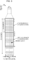
- Fig. 3 is a diagram illustrating the configuration of the slot according to the present embodiment.
- a normal cyclic prefix (CP) is applied to the OFDM symbol.
- an extended cyclic prefix (CP) may be applied to the OFDM symbol.
- the physical signal or the physical channel that is transmitted to each of the slots are expressed by a resource grid.
- the horizontal axis is a time axis and the vertical axis is a frequency axis.
- the resource grid is defined by multiple subcarriers and multiple OFDM symbols.
- the resource grid is defined by multiple subcarriers and multiple SC-FDMA symbols.
- the number of subcarriers that constitute one slot depends on a cell bandwidth.
- the number of OFDM symbols or SC-FDMA symbols that constitute one slot is 7.
- Each of the elements within the resource grid is referred to as a resource element.
- the resource element is identified using a subcarrier number, and an OFDM symbol or SC-FDMA symbol number.
- a resource block is used to express allocation of a certain physical channel (the PDSCH, the PUSCH, or the like) to resource elements.
- the resource block is defined by a virtual resource block and a physical resource block.
- a certain physical channel is first allocated to the virtual resource block. Thereafter, the virtual resource block is mapped to the physical resource block.
- One physical resource block is defined by 7 consecutive OFDM symbols or SC-FDMA symbols in a time domain and by 12 consecutive subcarriers in a frequency domain. Therefore, one physical resource block is configured from (7 ⁇ 12) resource elements.
- one physical resource block corresponds to one slot in the time domain, and corresponds to 180 kHz in the frequency domain.
- the physical resource blocks are numbered from 0 in the frequency domain.
- Fig. 4 is a diagram illustrating one example of allocation of the physical channel and mapping of the physical signal to the downlink subframe according to the present embodiment.
- the horizontal axis is a time axis and the vertical axis is a frequency axis.
- the base station device 3 may transmit the downlink physical channel (the PBCH, the PCFICH, the PHICH, the PDCCH, the EPDCCH, or the PDSCH), and the downlink physical signal (the synchronization signal or the downlink reference signal).
- the PBCH is transmitted only on subframe 0 within the radio frame.
- the downlink reference signal is mapped to the resource elements that are distributed in the frequency domain and the time domain. The downlink reference signal is not illustrated in Fig. 4 for brief description.
- multiple PDCCH's may be frequency-multiplexed or time-multiplexed in a PDCCH region.
- Multiple EPDCCH's may be frequency-multiplexed, time-multiplexed, and space-multiplexed in an EPDCCH region.
- Multiple PDSCH's may be frequency-multiplexed and time-multiplexed in a PDSCH region.
- the PDCCH and, the PDSCH or the EPDCCH may be time-multiplexed.
- the PDSCH and the EPDCCH may be frequency-multiplexed.
- Fig. 5 is a diagram illustrating one example of the allocation of the physical channel and the physical signal in the uplink subframe according to the present embodiment.
- the horizontal axis is a time axis and the vertical axis is a frequency axis.
- the mobile station device 1 may transmit the uplink physical channel (the PUCCH, the PUSCH or the PRACH) and the uplink physical signal (the DMRS or the SRS).
- the PUCCH the uplink physical channel
- the DMRS or the SRS uplink physical signal
- the PUCCH the uplink physical signal
- a PUCCH region multiple PUCCH's are frequency-multiplexed, time-multiplexed, and code-multiplexed.
- a PUSCH region multiple PUSCH's are frequency-multiplexed and space-multiplexed.
- the PUCCH and the PUSCH may be frequency-multiplexed.
- the PRACH may be allocated over a single sub frame or two subframes. Furthermore, multiple PR
- the SRS is transmitted using the last SC-FDMA symbol within the uplink subframe.
- the SRS is mapped to the last SC-FDMA symbol within the uplink subframe.
- the mobile station device 1 cannot transmit the SRS and the PUCCH/PUSCH/PRACH at the same time in a single SC-FDMA symbol in a single cell.
- the mobile station device 1 can transmit the PUSCH and/or the PUCCH using the SC-FDMA symbol with the last SC-FDMA symbol within the uplink subframe being excluded, and can transmit the SRS using the last SC-FDMA symbol within the uplink subframe.
- the mobile station device 1 can transmit both of the SRS and the PUSCH/PUCCH at the same time.
- the DMRS is time-multiplexed together with the PUCCH or the PUSCH.
- the DMRS is not illustrated in Fig. 5 for brief description.
- Fig. 6 is a diagram illustrating one example of the allocation of the physical channel and the mapping of the physical signals to the special subframe according to the present embodiment.
- the horizontal axis is a time axis and the vertical axis is a frequency axis.
- the DwPTS is configured from first to 10-th SC-FDMA symbols within the special subframe
- the GP is configured from 11-th and 12-th SC-FDMA symbols within the special subframe
- the UpPTS is configured from 13-th and 14-th SC-FDMA symbols within the special subframe.
- the base station device 3 may transmit the PCFICH, the PHICH, the PDCCH, the EPDCCH, the PDSCH, the synchronization signal, and the downlink reference signal, in the DwPTS of the special subframe.
- the base station device 3 does not transmit the PBCH in the DwPTS of the special subframe.
- the mobile station device 1 may transmit the PRACH and the SRS in the UpPTS of the special subframe. To be more precise, the mobile station device 1 does not transmit the PUCCH, the PUSCH, and the DMRS in the UpPTS of the special subframe.
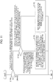
- Fig. 7 is a schematic block diagram illustrating a configuration of the mobile station device 1 according to the present invention.
- the mobile station device 1 is configured to include a higher layer processing unit 101, a control unit 103, a reception unit 105, a transmission unit 107, and a transmit and receive antenna unit 109.
- the higher layer processing unit 101 is configured to include a radio resource control unit 1011, a subframe setting unit 1013, a scheduling information interpretation unit 1015, and a channel state information (CSI) report control unit 1017.
- the reception unit 105 is configured to include a decoding unit 1051, a demodulation unit 1053, a demultiplexing unit 1055, a radio reception unit 1057, and a channel measurement unit 1059.
- the transmission unit 107 is configured to include a coding unit 1071, a modulation unit 1073, a multiplexing unit 1075, a radio transmission unit 1077, and an uplink reference signal generation unit 1079.
- the higher layer processing unit 101 outputs the uplink data (the transport block) generated by a user operation and the like, to the transmission unit 107. Furthermore, the higher layer processing unit 101 performs processing of a medium access control (MAC) layer, a packet data convergence protocol (PDCP) layer, a radio link control (RLC) layer, and a radio resource control (RRC) layer.
- MAC medium access control
- PDCP packet data convergence protocol
- RLC radio link control
- RRC radio resource control
- the radio resource control unit 1011 that is included in the higher layer processing unit 101 performs management of various pieces of configuration information of the mobile station device 1 itself. Furthermore, the radio resource control unit 1011 generates information that is arranged in each channel for uplink, and outputs the generated information to the transmission unit 107.
- the subframe setting unit 1013 that is included in the higher layer processing unit 101 manages a first uplink reference UL-DL configuration, a first downlink reference UL-DL configuration, a second uplink reference UL-DL configuration, a second downlink reference UL-DL configuration, and a transmission direction UL-DL configuration (transmission direction configuration).
- the subframe setting unit 1013 sets the first uplink reference UL-DL configuration, the first downlink reference UL-DL configuration, the second uplink reference UL-DL configuration, the second downlink reference UL-DL configuration, and the transmission direction UL-DL configuration. Furthermore, the subframe setting unit 1013 sets at least two subframe sets.
- the scheduling information interpretation unit 1015 that is included in the higher layer processing unit 101 interprets the DCI format (scheduling information) that is received through the reception unit 105, generates control information for performing control of the reception unit 105 and the transmission unit 107 based on a result of interpreting the DCI format, and outputs the generated control information to the control unit 103.
- the scheduling information interpretation unit 1015 additionally determines timing at which transmission processing and reception processing are performed, based on the first uplink reference UL-DL configuration, the first downlink reference UL-DL configuration, the second uplink reference UL-DL configuration, the second downlink reference UL-DL configuration, and/or the transmission direction UL-DL configuration.
- a CSI report control unit 1017 specifies a CSI reference resource.
- the CSI report control unit 1017 instructs the channel measurement unit 1059 to derive a CQI relating to the CSI reference resource.
- the CSI report control unit 1017 instructs the transmission unit 107 to transmit the CQI.
- the CSI report control unit 1017 sets a configuration that is used when the channel measurement unit 1059 calculates the CQI.
- the control unit 103 generates a control signal for performing the control of the reception unit 105 and the transmission unit 107 based on control information from the higher layer processing unit 101.
- the control unit 103 outputs the generated control signal to the reception unit 105 and the transmission unit 107, and performs the control of the reception unit 105 and the transmission unit 107.
- the reception unit 105 demultiplexes, demodulates, and decodes a reception signal that is received from the base station device 3 through the transmit and receive antenna 109, and outputs the resulting information to the higher layer processing unit 101.
- the radio reception unit 1057 converts (down-converts) a downlink signal that is received through the transmit and receive antenna unit 109 into an intermediate frequency, removes unnecessary frequency components, controls an amplification level in such a manner as to suitably maintain a signal level, performs orthogonal demodulation based on an in-phase component and an orthogonal component of the received signal, and converts the resulting orthogonally-demodulated analog signal into a digital signal.
- the radio reception unit 1057 removes a portion equivalent to a guard interval (GI) from the digital signal that results from the conversion, performs fast Fourier Transform (FFT) on the signal from which the guard interval is removed, and extracts a signal in the frequency domain.
- GI guard interval
- FFT fast Fourier Transform
- the demultiplexing unit 1055 demultiplexes the extracted signal into the PHICH, the PDCCH, the EPDCCH, the PDSCH, and the downlink reference signal. Furthermore, the demultiplexing unit 1055 makes an adjustment of channels, that is, the PHICH, the PDCCH, the EPDCCH, and the PDSCH, from a channel estimate that is input from the channel measurement unit 1059. Furthermore, the demultiplexing unit 1055 outputs the downlink reference signal, which results from the demultiplexing, to the channel measurement unit 1059.
- the demodulation unit 1053 multiplies the PHICH by a corresponding code for composition, performs demodulation in compliance with a Binary Phase Shift Keying (BPSK) modulation scheme on the resulting composite signal, and outputs a result of the demodulation to the decoding unit 1051.
- the decoding unit 1051 decodes the PHICH destined for the mobile station device 1 itself, and outputs the HARQ indicator that results from the decoding to the higher layer processing unit 101.
- the demodulation unit 1053 performs the demodulation in compliance with a QPSK modulation scheme on the PDCCH and/or the EPDCCH, and outputs a result of the demodulation to the decoding unit 1051.
- the decoding unit 1051 attempts to perform the decoding of the PDCCH and/or the EPDCCH. In a case where the decoding unit 1051 succeeds in the decoding, the decoding unit 1051 outputs downlink control information that results from the decoding and an RNTI to which the downlink control information corresponds, to the higher layer processing unit 101.
- the demodulation unit 1053 performs the demodulation on the PDSCH in compliance with the modulation scheme that is notified with the downlink grant, such as Quadrature Phase Shift keying (QPSK), 16 Quadrature Amplitude Modulation (QAM), or 64 QAM, and outputs a result of the demodulation to the decoding unit 1051.
- the decoding unit 1051 performs the decoding based on information relating to a coding rate that is notified with the downlink control information, and outputs to the higher layer processing unit 101 the downlink data (the transport block) that results from the decoding.
- the channel measurement unit 1059 measures a downlink path loss or a channel state from the downlink reference signal that is input from the demultiplexing unit 1055, and outputs the measured path loss or channel state to the higher layer processing unit 101. Furthermore, the channel measurement unit 1059 calculates a downlink channel estimate from the downlink reference signal and outputs the calculated downlink channel estimate to the demultiplexing unit 1055. The channel measurement unit 1059 measures channel measurement and/or interference measurement in order to calculate the CQI.
- the transmission unit 107 generates the uplink reference signal in accordance with the control signal, which is input from the control unit 103, performs the coding and the modulation on the uplink data (the transport block), which is input from the higher layer processing unit 101, multiplexes the PUCCH, the PUSCH, and the generated uplink reference signal, and transmits a result of the multiplexing to the base station device 3 through the transmit and receive antenna 109.
- the coding unit 1071 performs the coding, such as convolutional coding and block coding, on the uplink control information that is input from the higher layer processing unit 101. Furthermore, the coding unit 1071 performs turbo coding, based on information that is used for the scheduling of PUSCH.
- the modulation unit 1073 performs the modulation on coded bits, which are input from the coding unit 1071, in compliance with the modulation scheme that is notified with the downlink control information, such as the BPSK, the QPSK, the 16 QAM, or the 64 QAM, or in compliance with a modulation scheme that is prescribed in advance for every channel. Based on the information that is used for the scheduling of the PUSCH, the modulation unit 1073 determines the number of sequences of pieces of data that are space-multiplexed, maps multiple pieces of uplink data that are transmitted on the same PUSCH, to multiple sequences, by using Multiple Input Multiple Output Spatial Multiplexing (MIMO SM), and performs precoding on the sequences.
- MIMO SM Multiple Input Multiple Output Spatial Multiplexing
- the uplink reference signal generation unit 1079 generates a sequence that is acquired according to a rule (formula) that is prescribed in advance, based on a physical cell identifier (which is also referred to as a physical cell identity (PCI), a CELL ID, or the like) for identifying the base station device 3, a bandwidth to which the uplink reference signal is mapped, a cyclic shift that is notified with the uplink grant, a parameter value for generation of a DMRS sequence, and the like.
- a rule which is also referred to as a physical cell identity (PCI), a CELL ID, or the like
- PCI physical cell identity
- CELL ID a physical cell identity
- the multiplexing unit 1075 rearranges modulation symbols of the PUSCH in parallel and then performs Discrete Fourier Transform (DFT) on the rearranged modulation symbols.
- DFT Discrete Fourier Transform
- the multiplexing unit 1075 multiplexes PUCCH and PUSCH signals and the generated uplink reference signal for every transmit antenna port. To be more precise, the multiplexing unit 1075 maps the PUCCH and PUSCH signals and the generated uplink reference signal to the resource elements for every transmit antenna port.
- the radio transmission unit 1077 performs Inverse Fast Fourier Transform (IFFT) on a signal that results from the multiplexing, performs the modulation in compliance with an SC-FDMA scheme, generates an SC-FDMA symbol, attaches the guard interval to the SC-FDMA-modulated SC-FDMA symbol, generates a digital signal in a baseband, converts the digital signal in the baseband into an analog signal, generates an in-phase component and an orthogonal component in an intermediate frequency from the analog signal, removes frequency components unnecessary for an intermediate frequency band, converts (up-converts) the signal in the intermediate frequency into a signal in a high frequency, removes unnecessary frequency components, performs power amplification, and outputs a final result to the transmit and receive antenna 109 for transmission.
- IFFT Inverse Fast Fourier Transform
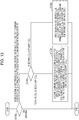
- Fig. 8 is a schematic block diagram illustrating a configuration of the base station device 3 according to the present embodiment.
- the base station device 3 is configured to include a higher layer processing unit 301, a control unit 303, a reception unit 305, a transmission unit 307, and a transmit and receive antenna 309.
- the higher layer processing unit 301 is configured to include a radio resource control unit 3011, a subframe setting unit 3013, a scheduling unit 3015, and a CSI report control unit 3017.
- the reception unit 305 is configured to include a decoding unit 3051, a demodulation unit 3053, a demultiplexing unit 3055, a radio reception unit 3057, and a channel measurement unit 3059.
- the transmission unit 307 is configured to include a coding unit 3071, a modulation unit 3073, a multiplexing unit 3075, a radio transmission unit 3077, and a downlink reference signal generation unit 3079.
- the higher layer processing unit 301 performs the processing of the Medium Access Control (MAC) layer, the packet data convergence protocol (PDCP) layer, the radio link control (RLC) layer, and the radio resource control (RRC) layer. Furthermore, the higher layer processing unit 301 generates a control signal in order to perform control of the reception unit 305 and the transmission unit 307, and outputs the generated control information to the control unit 303.
- MAC Medium Access Control
- PDCP packet data convergence protocol
- RLC radio link control
- RRC radio resource control
- the radio resource control unit 3011 that is included in the higher layer processing unit 301 generates, or acquires from a higher level node, the downlink data (the transport block) that is arranged in the downlink PDSCH, system information, the RRC message, the MAC control element (CE), and the like, and outputs a result of the generation or of the acquirement to the transmission unit 307. Furthermore, the radio resource control unit 3011 manages various pieces of configuration information on each of the mobile station devices 1.
- the sub frame setting unit 3013 that is included in the higher layer processing unit 301 performs management of the first uplink reference UL-DL configuration, the first downlink reference UL-DL configuration, the second uplink reference UL-DL configuration, the second downlink reference UL-DL configuration, and the transmission direction UL-DL configuration, on each of the mobile station devices 1.
- the sub frame setting unit 3013 sets the first uplink reference UL-DL configuration, the first downlink reference UL-DL configuration, the second uplink reference UL-DL configuration, the second downlink reference UL-DL configuration, and the transmission direction UL-DL configuration, for each of the mobile station devices 1.
- the subframe setting unit 3013 generates first information showing the first uplink reference UL-DL configuration, second information showing the first downlink reference UL-DL configuration, and third information showing the transmission direction UL-DL configuration.
- the subframe setting unit 3013 outputs the first information, the second information, and the third information to the mobile station device 1 through the transmission unit 307.
- the base station device 3 may determine the first uplink reference UL-DL configuration, the first downlink reference UL-DL configuration, the second uplink reference UL-DL configuration, the second downlink reference UL-DL configuration, and/or the transmission direction UL-DL configuration, for the mobile station device 1. Furthermore, the base station device 3 may be instructed by the higher level node to set the first uplink reference UL-DL configuration, the first downlink reference UL-DL configuration, the second uplink reference UL-DL configuration, the second downlink reference UL-DL configuration, and/or the transmission direction UL-DL configuration, for the mobile station device 1.
- the subframe setting unit 3013 may determine the first uplink reference UL-DL configuration, the first downlink reference UL-DL configuration, the second uplink reference UL-DL configuration, the second downlink reference UL-DL configuration, and/or the transmission direction UL-DL configuration.
- the subframe setting unit 3013 performs management of at least two subframe sets.
- the subframe setting unit 3013 may configure at least two subframe sets for each of the mobile station devices 1.
- the subframe setting unit 3013 may configure at least two subframe sets on each of the serving cells.
- the subframe setting unit 3013 may configure at least two subframe sets for each CSI process.
- the subframe setting unit 3013 transmits information showing at least two subframe sets to the mobile station device 1 through the transmission unit 307.
- the scheduling unit 3015 that is included in the higher layer processing unit 301 determines a frequency and a subframe to which the physical channel (the PDSCH and the PUSCH) is allocated, the coding rate and modulation scheme for the physical channel (the PDSCH and the PUSCH), the transmission power, and the like, from the received channel state information and from the channel estimate, channel quality, or the like that is input from the channel measurement unit 3059.
- the scheduling unit 3015 determines whether, in a flexible subframe, the downlink physical channel and/or the downlink physical signal is scheduled or the uplink physical channel and/or the uplink physical signal is scheduled.
- the scheduling unit 3015 generates the control information (for example, the DCI format) in order to perform the control of the reception unit 305 and the transmission unit 307 based on a result of the scheduling, and outputs the generated information to the control unit 303.
- the control information for example, the DCI format
- the scheduling unit 3015 generates the information that is used for the scheduling of the physical channel (the PDSCH and the PUSCH), based on the result of the scheduling.
- the scheduling unit 3015 additionally determines the timing at which the transmission processing and the reception processing are performed, based on the first uplink reference UL-DL configuration, the first downlink reference UL-DL configuration, the second uplink reference UL-DL configuration, the second downlink reference UL-DL configuration, and/or the transmission direction UL-DL configuration.
- the CSI report control unit 3017 that is included in the higher layer processing unit 301 controls a CSI report by the mobile station device 1.
- the CSI report control unit 3017 transmits information that is assumed in order for the mobile station device 1 to derive the CQI in the CSI reference resource, and that shows various configurations, to the mobile station device 1 through the transmission unit 307.
- the control unit 303 Based on the control information from the higher layer processing unit 301, the control unit 303 generates a control signal for performing the control of the reception unit 305 and the transmission unit 307. The control unit 303 outputs the generated control signal to the reception unit 305 and the transmission unit 307, and performs the control of the reception unit 305 and the transmission unit 307.
- the reception unit 305 demultiplexes, demodulates, and decodes the reception signal that is received from the mobile station device 1 through the transmit and receive antenna 309, and outputs the resulting information to the higher layer processing unit 301.
- the radio reception unit 3057 converts (down-converts) an uplink signal that is received through the transmit and receive antenna unit 309 into an intermediate frequency, removes unnecessary frequency components, controls an amplification level in such a manner as to suitably maintain a signal level, performs orthogonal demodulation based on an in-phase component and an orthogonal component of the received signal, and converts the resulting orthogonally-demodulated analog signal into a digital signal.
- the radio reception unit 3057 removes a portion corresponding to the guard interval (GI) from the digital signal that results from the conversion.
- the radio reception unit 3057 performs the Fast Fourier Transform (FFT) on the signal from which the guard interval is removed, and outputs the resulting signal to the demultiplexing unit 3055 that extracts the signal in the frequency domain.
- FFT Fast Fourier Transform
- the demultiplexing unit 1055 demultiplexes the signal that is input from the radio reception unit 3057 into the PUCCH, the PUSCH, and the signal such as the uplink reference signal. Moreover, the demultiplexing is performed based on radio resource allocation information that is determined in advance by the base station device 3, using the radio resource control unit 3011, and that is included in the uplink grant notified to each of the mobile station devices 1. Furthermore, the demultiplexing unit 3055 makes an adjustment of channels, that is, the PUCCH and the PUSCH, from the channel estimate that is input from the channel measurement unit 3059. Furthermore, the demultiplexing unit 3055 outputs an uplink reference signal that results from the demultiplexing, to the channel measurement unit 3059.
- the demodulation unit 3053 performs Inverse Discrete Fourier Transform (IDFT) on the PUSCH, acquires the modulation symbol, and performs reception signal demodulation on each of the modulation symbols of the PUCCH and the PUSCH, using the modulation scheme that is prescribed in advance, such as the Binary Phase Shift Keying (BPSK), the QPSK, the 16 QAM, or the 64 QAM, or using the modulation scheme that the base station device 3 itself notifies, in advance with the uplink grant, to each of the mobile station devices 1.
- IDFT Inverse Discrete Fourier Transform
- the demodulation unit 3053 demultiplexes the modulation symbols of the multiple pieces of uplink data that are transmitted on the same PUSCH by using the MIMO SM, based on the number of space-multiplexed sequences that is notified in advance with the uplink grant to each of the mobile station devices 1 and on information indicating the precoding that is performed on the sequences.
- the decoding unit 3051 performs the decoding on the coded bits of the PUCCH and the PUSCH, which are demodulated, at the coding rate in compliance with a coding scheme prescribed in advance, which is prescribed in advance, or which is notified in advance with the uplink grant to the mobile station device 1 by the base station device 3 itself, and outputs to the higher layer processing unit 101 the uplink data and the uplink control information that are decoded.
- the decoding unit 3051 performs the decoding using the coded bits that are input from the higher layer processing unit 301 and that are retained in a HARQ buffer, and the demodulated coded bits.
- the channel measurement unit 309 measures the channel estimate or the channel quality, and the like, based on the uplink reference signal that is input from the demultiplexing unit 3055, and outputs a result of the measurement to the demultiplexing unit 3055 and the higher layer processing unit 301.
- the transmission unit 307 generates the downlink reference signal in accordance with the control signal that is input from the control unit 303, codes and modulates the HARQ indicator, the downlink control information, and the downlink data that are input from the higher layer processing unit 301, multiplexes the PHICH, the PDCCH, the EPDCCH, the PDSCH, and the downlink reference signal, and transmits a result of the multiplexing to the mobile station device 1 through the transmit and receive antenna 309.
- the coding unit 3071 performs the coding on the HARQ indicator, the downlink control information, and the downlink data that are input from the higher layer processing unit 301, using the coding scheme that is prescribed in advance, such as the block coding, the convolutional coding, or the turbo coding, or using the coding scheme that is determined by the radio resource control unit 3011.
- the modulation unit 3073 performs the modulation on the coded bits that are input from the coding unit 3071, using the modulation scheme that is prescribed in advance, such as the BPSK, the QPSK, the 16 QAM, or the 64 QAM, or using the modulation scheme that is determined by the radio resource control unit 3011.
- the downlink reference signal generation unit 3079 generates as the downlink reference signal a sequence that is already known to the mobile station device 1 and that is acquired according to a rule that is prescribed in advance based on the physical cell identifier (PCI) for identifying the base station device 3, and the like.
- the multiplexing unit 3075 multiplexes the modulated modulation symbol of each channel and the generated downlink reference signal. To be more precise, the multiplexing unit 3075 arranges the modulated modulation symbol of each channel and the generated downlink reference signal in the resource elements.
- the radio transmission unit 3077 performs the Inverse Fast Fourier Transform (IFFT) on the modulation symbol that results from the multiplexing, performs the modulation in compliance with an OFDM scheme, generates an OFDM symbol, attaches the guard interval to the OFDM-modulated OFDM symbol, generates a digital signal in a baseband, converts the digital signal in the baseband into an analog signal, generates an in-phase component and an orthogonal component in an intermediate frequency from the analog signal, removes frequency components unnecessary for an intermediate frequency band, converts (up-converts) the signal in the intermediate frequency into a signal in a high frequency, removes unnecessary frequency components, performs power amplification, and outputs a final result to the transmit and receive antenna 309 for transmission.
- IFFT Inverse Fast Fourier Transform
- the first uplink reference UL-DL configuration uplink reference uplink-downlink configuration
- the first downlink reference UL-DL configuration downlink reference uplink-downlink configuration
- the second uplink reference UL-DL configuration the second downlink reference UL-DL configuration
- the transmission direction UL-DL configuration transmission direction uplink-downlink configuration
- the first uplink reference UL-DL configuration, the first downlink reference UL-DL configuration, the second uplink reference UL-DL configuration, a second downlink reference UL-DL configuration, and the transmission direction UL-DL configuration are defined by an uplink-downlink configuration (UL-DL configuration).
- the uplink-downlink configuration is a configuration relating to a pattern of a subframe within the radio frame. That is, the uplink-downlink configuration shows which of the downlink subframe, the uplink subframe and the special subframe each of the subframes within the radio frame is.
- the first uplink reference UL-DL configuration, the second uplink reference UL-DL configuration, the first downlink reference UL-DL configuration, the second downlink reference UL-DL configuration, and the transmission direction UL-DL configuration are defined by patterns of the downlink subframe, the uplink subframe, and the special subframe within the radio frame.
- the patterns of the downlink subframe, the uplink subframe, and the special subframe shows which of the downlink subframe, the uplink subframe, and the special subframe each of subframes #0 to #9 is, and are preferably expressed by arbitrary combinations of D, U, and S (which shows the downlink subframe, the uplink subframe, and the special subframe, respectively), in each of which a sum of lengths of D, U, and S is 10. More preferably, the head subframe (to be more precise, subframe #0) is D, and the second subframe is S (to be more precise, subframe #1).
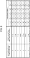
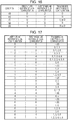
- Fig. 9 illustrates one example of the uplink-downlink configuration according to the present embodiment.
- D denotes a downlink subframe
- U denotes an uplink subframe
- S denotes a special subframe.
- subframe 1 within the radio frame is always a special subframe.
- subframes 0 and 5 are always reserved for the downlink transmission, and subframe 2 is always reserved for the uplink transmission.
- subframe 6 within the radio frame is a special subframe.
- subframe 6 within the radio frame is a downlink subframe.
- the first uplink reference UL-DL configuration is also referred to as a first parameter, a first configuration or a serving cell uplink-downlink configuration.
- the first downlink reference UL-DL configuration is also referred to as a second parameter or a second configuration.
- the second uplink reference UL-DL configuration is also referred to as a third parameter or a third configuration.
- the second downlink reference UL-DL configuration is also referred to as a fourth parameter or a fourth configuration.
- the transmission direction UL-DL configuration is also referred to as a fifth parameter or a fifth configuration.
- Setting of uplink-downlink configuration i as the first or second uplink reference UL-DL configuration is referred to as setting of first or second uplink reference UL-DL configuration i.
- Setting of uplink-downlink configuration i as the first or second downlink reference UL-DL configuration is referred to as setting of first or second downlink reference UL-DL configuration i.
- Setting of uplink-downlink configuration i as the transmission direction UL-DL configuration is referred to as setting of transmission direction UL-DL configuration i.
- a method of setting the first uplink reference UL-DL configuration, the first downlink reference UL-DL configuration, and the transmission direction UL-DL configuration will be described below.
- the base station device 3 sets the first uplink reference UL-DL configuration, the first downlink reference UL-DL configuration, and the transmission direction UL-DL configuration.
- the base station device 3 transmits the first information (TDD-Config) showing the first uplink reference UL-DL configuration, the second information showing the first downlink reference UL-DL configuration, and the third information showing the transmission direction UL-DL configuration, with the first information, the second information, and the third information being included in at least one of a MIB, a system information block type 1 message, a system information message, an RRC message, a MAC control element (CE), and physical layer control information (for example, a DCI format).
- the base station device 3 may include the first information, the second information, and the third information in any one of the MIB, the system information block type 1 message, the system information message, the RRC message, the MAC control element (CE), and the physical layer control information (for example, the DCI format), depending on a situation.
- the first uplink reference UL-DL configuration, the second uplink reference UL-DL configuration, the first downlink reference UL-DL configuration, the second downlink reference UL-DL configuration, and the transmission direction UL-DL configuration may be defied.
- the base station device 3 transmits the first information, the second information, and the third information to the mobile station device 1 for which multiple serving cells are set. Moreover, for each of the serving cells, the first information, the second information, and the third information may be defined.
- the base station device 3 may transmit the first information for the primary cell, the second information for the primary cell, the third information for the primary cell, the first information for the secondary cell, the second information for the secondary cell, and the third information for the secondary cell, to the mobile station device 1 for which two serving cells, each being configured from one primary cell and one secondary cell, is set for.
- the mobile station device 1 for which multiple serving cells are set may set the first uplink reference UL-DL configuration, the first downlink reference UL-DL configuration, and the transmission direction DL-UL configuration for each of the serving cells, based on the first information, the second information, and the third information.
- the mobile station device 1 for which the two serving cells, each being configured from one primary cell and one secondary cell, are set may set the first uplink reference UL-DL configuration for the primary cell, the first downlink reference UL-DL configuration for the primary cell, the transmission direction DL-UL configuration for the primary cell, the first uplink reference UL-DL configuration for the secondary cell, the first downlink reference UL-DL configuration for the secondary cell, and the transmission direction DL-UL configuration for the secondary cell.
- the first information for the primary cell is desirably included in the system information block type 1 message or the RRC message.
- the first information for the secondary cell is desirably included in the RRC message.
- the second information for the primary cell is desirably included in the system information block type 1 message, the system information message, or the RRC message.
- the second information for the secondary cell is desirably included in the RRC message.
- the third information is desirably included in the physical layer control information (for example, the DCI format).
- the first information is desirably common to multiple mobile station devices 1 within a cell.
- the second information may be common to the multiple mobile station devices 1 within the cell and may be dedicated to the mobile station device 1.
- the third information may be common to the multiple mobile station devices 1 within the cell and may be dedicated to the mobile station device 1.
- the system information block type 1 message includes information showing a configuration (lengths of DwPTS, GP, and UpPTS) of a special subframe.
- the system information block type 1 message is cell-specific information.
- the system information message is transmitted through the PDSCH.
- the system information message is cell-specific information.
- the system information message includes a system information block X other than the system information block type-1.
- the RRC message is transmitted through the PDSCH.
- the RRC message is information or a signal that is processed in an RRC layer.
- the RRC message may be common to multiple mobile station devices 1 within a cell, and may be dedicated to a specific mobile station device 1.
- the MAC CE is transmitted through the PDSCH.
- the MAC CE is information or a signal that is processed in a MAC layer.
- the mobile station device 1 desirably sets (enables) the first uplink reference UL-DL configuration, the first downlink reference UL-DL configuration, and/or the transmission direction UL-DL configuration in a subframe n.
- k is 4 or 8.
- a subframe n + k is a subframe on which to transmit the HARQ-ACK (the ACK) for the downlink physical channel (for example, the PDCCH/EPDCCH) that is used for transmission of the physical layer control information (for example, the DCI format).
- k is determined based on a table in Fig. 21 and a current first or second downlink reference UL-DL configuration.
- the mobile station device 1 desirably sets (enables) the transmission direction UL-DL configuration in the radio frame n.
- k is 1.
- the third information that is received on the radio frame n - k may be effective only for the radio frame n.
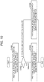
- Fig. 10 is a flowchart illustrating a method of setting the first uplink reference UL-DL configuration and the first downlink reference UL-DL configuration according to the present embodiment.
- the mobile station device 1 performs a setting method in Fig. 10 on each of the multiple serving cells.
- the mobile station device 1 sets the first uplink reference UL-DL configuration for a certain serving cell based on the first information (S1000).
- the mobile station device 1 determines whether or not the second information for the certain serving cell is received (S1002). In a case where the second information for the certain serving cell is received, the mobile station device 1 sets the first downlink reference UL-DL configuration for the serving cell, based on the second information for the certain serving cell (S1006). In a case where the second information for the certain serving cell is not received (else or otherwise), the mobile station device 1 sets the first downlink reference UL-DL configuration for the serving cell, based on the first information for the certain serving cell (S1004).
- the serving cell for which the first uplink reference UL-DL configuration and the first downlink reference UL-DL configuration are set based on the first information is also referred to as a serving cell for which timing TDD is not set.
- the serving cell for which the first downlink reference UL-DL configuration is set based on the second information is also referred to as a serving cell for which the timing TDD is set.
- the mobile station device 1 receives the second information and, based on the second information, determines a subframe that is available for the transmission of the uplink signal. Next, the mobile station device 1 monitors the third information. In a case where the third information is received, the mobile station device 1 determines a subframe that is available for the transmission of the uplink signal based on the third information.
- the base station device 3 transmits third information to the mobile station device 1 using the PDCCH/EPDCCH.
- the third information performs control of the timing TDD operation within a coverage that is provided by the base station device 3 (a cell).
- the third information is transmitted and received in a common search space (CSS) or a UE-specific search space (USS).
- CSS common search space
- USS UE-specific search space
- the CSS is a region in which multiple mobile station devices 1, in common, performs monitoring of the PDCCH/EPDCCH.
- the USS is a region that is defined based on at least the C-RNTI.
- the C-RNTI is an identifier that is allocated in a manner that is unique to the mobile station device 1.
- the C-RNTI may be used for transmission of the DCI format that includes the third information (information indicating transmission direction for a sub frame).
- the RNTI that is different from the C-RNTI and the SPS C-RNTI may be used for the transmission of the DCI format that includes the third information (information indicating the transmission direction for the subframe).
- the RNTI is referred to as an X-RNTI.
- the CRC parity bit that is attached to the DCI format that includes the third information is scrambled with the C-RNTI or the X-RNTI.
- a subframe in which the mobile station device 1 monitors the PDCCH/EPDCCH that includes the third information may be limited.
- the base station device 3 may control a subframe in which the mobile station device 1 monitors the PDCCH/EPDCCH that includes the third information.
- the base station device 3 may transmit information indicating the subframe in which the mobile station device 1 monitors the PDCCH/EPDCCH that includes the third information, to the mobile station device 1.
- the PDCCH/EPDCCH that includes the third information is allocated at intervals of 10 subframes.
- the mobile station device 1 monitors the third information at intervals of 10 subframes.
- the subframe to which the PDCCH/EPDCCH that includes the third information is allocated may be determined in advance.
- the third information may be arranged only in subframe 0 or 5 of the radio frame.
- the mobile station device 1 that starts the timing TDD operation performs the monitoring of the PDCCH/EPDCCH that includes the third information, in the subframe to which the PDCCH/EPDCCH that includes the third information is allocated.
- the mobile station device 1 attempts to decode the received signal, and determines whether or not the PDCCH/EPDCCH that includes the third information is detected. In a case where the PDCCH/EPDCCH that includes the third information is detected, the mobile station device 1 determines a subframe that is available for the transmission of the uplink signal, based on the detected third information. In a case where the PDCCH/EPDCCH that includes the third information is not detected, the mobile station device 1 may maintain the determination made so far of the subframe that is available for the transmission of the uplink signal.
- the mobile station device 1 and the base station device 3 set the second uplink reference UL-DL configuration.
- the mobile station device 1 and the base station device 3 may not set the second uplink reference UL-DL configuration.
- the first uplink reference UL-DL configurations for at least two serving cells are different from each other, the first uplink reference UL-DL configurations for all the serving cells are the same. In a case where one serving cell is set for the mobile station device 1, the mobile station device 1 and the base station device 3 may not set the second uplink reference UL-DL configuration.
- Fig. 11 is a flowchart illustrating a method of setting the second uplink reference UL-DL configuration according to the present embodiment.
- one primary cell and one secondary cell are set for the mobile station device 1.
- the mobile station device 1 performs the setting method in Fig. 11 on each of the primary cell and the secondary cell.
- the mobile station device 1 determines whether or not the first uplink reference UL-DL configuration for the primary cell and the first uplink reference UL-DL configuration for the second cell are different from each other (S1100). In a case where the first uplink reference UL-DL configuration for the primary cell and the first uplink reference UL-DL configuration for the secondary cell are the same, the mobile station device 1 ends processing that sets the second uplink reference UL-DL configuration, without setting the second uplink reference UL-DL configuration.
- the mobile station device 1 determines whether or not the serving cell is a primary cell or a secondary cell, and/or whether or not the serving cell is set in such a manner that the PDCCH/EPDCCH that is accompanied by a carrier indicator field (CIF) which corresponds to the serving cell is monitored (S1102).
- the serving cell is a primary cell or a secondary cell, and/or whether or not the serving cell is set in such a manner that the PDCCH/EPDCCH that is accompanied by a carrier indicator field (CIF) which corresponds to the serving cell is monitored (S1102).
- CIF carrier indicator field
- the mobile station device 1 sets the second uplink reference UL-DL configuration for the serving cell (the secondary cell), based on a pair that is formed by the first uplink reference UL-DL configuration for the different serving cell (the primary cell) and the first uplink reference UL-DL configuration for the serving cell (the serving cell) (S1104).
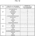
- the mobile station device 1 sets the second uplink reference UL-DL configuration for the serving cell (the secondary cell) based on a table in Fig. 12.
- Fig. 12 is a diagram illustrating a correspondence between a pair that is formed by the first uplink reference UL-DL configuration for a different serving cell (the primary cell) and the first uplink reference UL-DL configuration for the serving cell (the secondary cell), and the second uplink reference UL-DL configuration for the secondary cell, according to the present embodiment.
- a primary cell UL-DL configuration refers to the first uplink reference UL-DL configuration for the different serving cell (the primary cell).
- a secondary cell UL-DL configuration refers to the first uplink reference UL-DL configuration for the serving cell (the secondary cell).
- a second uplink reference UL-DL configuration 1 is set for the secondary cell.
- the mobile station device 1 sets the first uplink reference UL-DL configuration for the serving cell to the second uplink reference UL-DL configuration for the serving cell (S1106).
- the base station device 3 sets the second uplink reference UL-DL configuration based on the setting method in Fig. 11 .
- the monitoring of the PDCCH/EPDCCH that is accompanied by the CIF means attempting to decode the PDCCH or the EPDCCH according to the DCI format that includes the CIF.
- the CIF is a field to which a carrier indicator is mapped.
- a value of the carrier indicator shows a serving cell to which the DCI format to which the carrier indicator relates corresponds.
- the mobile station device 1 that is set in such a manner as to monitor the PDCCH/EPDCCH that is accompanied by the CIF which corresponds to a serving cell in a different serving cell monitors the PDCCH/EPDCCH that is accompanied by the CIF in the different serving cell.
- the mobile station device 1 that is set in such a manner as to monitor the PDCCH/EPDCCH which is accompanied by the CIF that corresponds to a serving cell in a different serving cell desirably receives the third information for the serving cell through the PDCCH/EPDCCH in the different serving cell.
- the mobile station device 1 that is not set in such a manner as to monitor the PDCCH/EPDCCH that is accompanied by the CIF which corresponds to a serving cell in the different serving cell monitors the PDCCH/EPDCCH that is accompanied by the CIF or is not accompanied by the CIF in the serving cell.
- the mobile station device 1 that is not set in such a manner as to monitor the PDCCH/EPDCCH which is accompanied by the CIF that corresponds to a serving cell in a different serving cell desirably receives the third information for the serving cell through the PDCCH/EPDCCH in the serving cell.
- the PDCCH/EPDCCH for the primary cell is transmitted in the primary cell.
- the third information for the primary cell is desirably transmitted through the PDCCH/EPDCCH in the primary cell.
- the base station device 3 transmits to the mobile station device 1 a parameter (cif-Presence-rlO) showing whether or not the CIF is included in the DCI format that is transmitted in the primary cell.
- the base station device 3 For each of the secondary cells, the base station device 3 transmits to the mobile station device 1 a parameter (CrossCarrierSchedulingConfig-r10) relating to cross carrier scheduling.
- a parameter (CrossCarrierSchedulingConfig-r10) relating to cross carrier scheduling.
- the parameter (CrossCarrierSchedulingConfig-r10) includes a parameter (schedulingCellInfo-r10) showing whether or not the PDCCH/EPDCCH that corresponds to a related secondary cell is transmitted in the secondary cell or is transmitted in a different serving cell.
- the parameter (schedulingCellInfo-r10) indicates that the PDCCH/EPDCCH which corresponds to a related secondary cell is transmitted on the secondary cell
- the parameter (schedulingCellInfo-r10) includes a parameter (cif-Presence-r10) showing whether or not the CIF is included in the DCI format that is transmitted in the secondary cell.
- the parameter (schedulingCellInfo-r10) indicates that the PDCCH/EPDCCH which corresponds to a related secondary cell is transmitted in a different serving cell
- the parameter (schedulingCellInfo-r10) includes a parameter (schedulingCellId) showing which serving cell the downlink allocation for the related secondary cell is sent in.
- the mobile station device 1 and the base station device 3 set the second downlink reference UL-DL configuration. In cases other than the case where the multiple serving cells are set for the mobile station device 1 and the first downlink reference UL-DL configurations for at least two serving cells are different from each other, the mobile station device 1 and the base station device 3 may not set the second downlink reference UL-DL configuration.
- the first downlink reference UL-DL configurations for at least two serving cells are different from each other, the first downlink reference UL-DL configurations for all the serving cells are the same. In the case where one serving cell is set for the mobile station device 1, the mobile station device 1 and the base station device 3 may not set the second downlink reference UL-DL configuration.
- Fig. 13 is a flowchart illustrating a method of setting the second downlink reference UL-DL configuration according to the present embodiment.
- one primary cell and one secondary cell are set for the mobile station device 1.
- the mobile station device 1 performs the setting method in Fig. 13 on each of the primary cell and the secondary cell.
- the mobile station device 1 determines whether or not the first downlink reference UL-DL configuration for the primary cell and the first downlink reference UL-DL configuration for the second cell are different from each other (S1300). In a case where the first downlink reference UL-DL configuration for the primary cell and the first downlink reference UL-DL configuration for the secondary cell are the same, the mobile station device 1 ends processing that sets the second downlink reference UL-DL configuration, without setting the second downlink reference UL-DL configuration.
- the mobile station device 1 determines whether or not the serving cell is a primary cell or a secondary cell (S1302).
- the second uplink reference UL-DL configuration for the serving cell (the secondary cell) is set based on the pair that is formed by the first downlink reference UL-DL configuration for the different serving cell (the primary cell) and the first downlink reference UL-DL configuration for the serving cell (the secondary cell) (S1304).
- the mobile station device 1 sets the second downlink reference UL-DL configuration for the serving cell (the secondary cell) based on a table in Fig. 14.
- Fig. 14 is a diagram illustrating a correspondence between a pair that is formed by the first downlink reference UL-DL configuration for the primary cell and the first downlink reference UL-DL configuration for the secondary cell, and the second downlink reference UL-DL configuration for the secondary cell, according to the present embodiment.
- the primary cell UL-DL configuration refers the first downlink reference UL-DL configuration for the primary cell.
- the secondary cell UL-DL configuration refers the first downlink reference UL-DL configuration for the secondary cell.
- the second downlink reference UL-DL configuration for the secondary cell is defined in set 1.
- the mobile station device 1 In a case where, in the primary cell, the mobile station device 1 is not set in such a manner as to monitor the PDCCH/EPDCCH that is accompanied by the CIF which corresponds to the secondary cell, and the pair that is formed by the first downlink reference UL-DL configuration for the primary cell and the first downlink reference UL-DL configuration for the secondary cell belongs to set 2 in Fig. 14 , the second downlink reference UL-DL configuration for the secondary cell is defined in set 2.
- the mobile station device 1 In a case where, in the primary cell, the mobile station device 1 is not set in such a manner as to monitor the PDCCH/EPDCCH that is accompanied by the CIF which corresponds to the secondary cell, and the pair that is formed by the first downlink reference UL-DL configuration for the primary cell and the first downlink reference UL-DL configuration for the secondary cell belongs to set 3 in Fig. 14 , the second downlink reference UL-DL configuration for the secondary cell is defined in set 3.
- the mobile station device 1 is set in such a manner as to monitor the PDCCH/EPDCCH that is accompanied by the CIF which corresponds to the secondary cell, and the pair that is formed by the first downlink reference UL-DL configuration for the primary cell and the first downlink reference UL-DL configuration for the secondary cell belongs to set 4 in Fig. 14 , the second downlink reference UL-DL configuration for the secondary cell is defined in set 4.
- the mobile station device 1 is set in such a manner as to monitor the PDCCH/EPDCCH that is accompanied by the CIF which corresponds to the secondary cell, and the pair that is formed by the first downlink reference UL-DL configuration for the primary cell and the first downlink reference UL-DL configuration for the secondary cell belongs to set 5 in Fig. 14 , the second downlink reference UL-DL configuration for the secondary cell is defined in set 5.
- a second downlink reference UL-DL configuration 1 is set for the secondary cell.
- the first downlink reference UL-DL configuration for the serving cell (the primary cell) is set to the second downlink reference UL-DL configuration for the serving cell (the primary cell) (S1306).
- the base station device 3 also sets the second downlink reference UL-DL configuration based on the setting method in Fig. 13 .
- the first uplink reference UL-DL configuration will be described below.
- the first uplink reference UL-DL configuration is at least used for specifying a subframe that is available or is not available for the uplink transmission in the serving cell.
- the mobile station device 1 does not perform the uplink transmission in the subframe that is indicated, as the downlink subframe, by the first uplink reference UL-DL configuration.
- the mobile station device 1 does not perform the uplink transmission in the DwPTS and the GP of the subframe that is indicated, as the special subframe, by the first uplink reference UL-DL configuration.
- the first downlink reference UL-DL configuration will be described below.
- the first downlink reference UL-DL configuration is at least used for specifying a subframe that is available or is not available for the downlink transmission in the serving cell.
- the mobile station device 1 does not perform the downlink transmission in the subframe that is indicated, as the uplink subframe, by the first downlink reference UL-DL configuration.
- the mobile station device 1 does not perform the downlink transmission in the UpPTS and the GP of the subframe that is indicated, as the special subframe, by the first downlink reference UL-DL configuration.
- the mobile station device 1 that sets the first downlink reference UL-DL configuration based on the first information may also perform measurement (for example, measurement relating to the channel state information) that uses the downlink signal in the DwPTS of the downlink subframe or the special subframe that is indicated by the first uplink reference UL-DL configuration or the first downlink reference UL-DL configuration.
- measurement for example, measurement relating to the channel state information
- the base station device 3 determines the downlink reference UL-DL configuration from a configuration set (set configuration) that is limited based on the first uplink reference UL-DL configuration.
- the first downlink reference UL-DL configuration is an element in the configuration set that is limited based on the first uplink reference UL-DL configuration.
- the condition set that is limited on the first uplink reference UL-DL configuration includes the uplink-downlink configuration that satisfies the following conditions (a) to (c).
- Fig. 15 is a diagram illustrating a relationship between the subframe that is indicated by the first uplink reference UL-DL configuration and the subframe that is indicated by the first downlink reference UL-DL configuration, according to the present embodiment.
- D denotes a downlink subframe
- U denotes an uplink subframe
- S denotes a special subframe.
- a subframe that is indicated, as a downlink subframe, by the first uplink reference UL-DL configuration is indicated as the downlink subframe.
- a subframe that is indicated, as uplink subframe, by the first uplink reference UL-DL configuration is indicated as an uplink subframe or a downlink subframe.
- a sub frame that is indicated, as a special sub frame, by the first uplink reference UL-DL configuration is indicated as a downlink subframe or a special subframe.
- the mobile station device 1 that sets the first downlink reference UL-DL configuration based on the first information can suitably perform the measurement that uses the downlink signal.
- the mobile station device 1 that sets the first downlink reference UL-DL configuration based on the second information may also perform the measurement (for example, the measurement relating to the channel state information) that uses the downlink signal in the DwPTS of the downlink subframe or the special subframe that is indicated by the first uplink reference UL-DL configuration.
- the measurement for example, the measurement relating to the channel state information
- the subframe that is indicated as the uplink subframe by the first uplink reference UL-DL configuration and that is indicated as the downlink subframe by the first downlink reference UL-DL configuration is also referred to as a first flexible subframe.
- the first flexible subframe is a subframe that is reserved for the uplink and downlink transmission.
- the subframe that is indicated as the special subframe by the first uplink reference UL-DL configuration and that is indicated as the downlink subframe by the first downlink reference UL-DL configuration is also referred to as a second flexible subframe.
- the second flexible subframe is a subframe that is reserved only for the downlink transmission.
- the second flexible subframe is a subframe that is reserved for the downlink transmission in the DwPTS and the uplink transmission in the UpPTS.
- the transmission direction UL-DL configuration will be described in detail below.
- the mobile station device 1 and the base station device 3 set the transmission direction UL-DL configuration relating to a transmission direction (uplink/downlink) in the subframe.
- the transmission direction UL-DL configuration is used to determine the transmission direction in the subframe.
- the mobile station device 1 controls the transmission in the first flexible subframe and the second flexible subframe based on the scheduling information (the DCI format and/or the HARQ-ACK) and the transmission direction UL-DL configuration.
- the base station device 3 transmits to the mobile station device 1 the third information that shows the transmission direction UL-DL configuration.
- the third information is information that indicates a subframe which is available for the uplink transmission.
- the third information is information that shows a subframe which is available for the downlink transmission.
- the third information is information that shows a subframe which is available for the uplink transmission in the UpPTS and for the downlink transmission in the DwPTS.
- the transmission direction UL-DL configuration is used to specify the transmission direction, in the subframe that is indicated, as the uplink subframe, by the first uplink reference UL-DL configuration and that is indicated, as the downlink subframe, by the first downlink reference UL-DL configuration, and/or in the subframe that is indicated, as the special subframe, by the first uplink reference UL-DL configuration and that is indicated, as the downlink subframe, by the first downlink reference UL-DL configuration.
- the transmission direction UL-DL configuration is used to specify the transmission direction in the subframe that is indicated as a subframe different from that in the first uplink reference UL-DL configuration and the first downlink reference UL-DL configuration.
- Fig. 16 is a diagram illustrating a relationship among the subframe that is indicated by the first uplink reference UL-DL configuration, the subframe that is indicated by the first downlink reference UL-DL configuration, and the subframe that is indicated by the transmission direction UL-DL configuration, according to the present embodiment.
- D denotes a downlink subframe
- U denotes an uplink subframe
- S denotes a special subframe.
- the base station device 3 determines the transmission direction UL-DL configuration from the configuration (the set configuration) that is limited based the first uplink reference UL-DL configuration and the first downlink reference UL-DL configuration.
- the transmission direction UL-DL configuration is an element in the configuration set that is limited based on the first uplink reference UL-DL configuration and the first downlink reference UL-DL configuration.
- the configuration set that is limited based on the first uplink reference UL-DL configuration and the first downlink reference UL-DL configuration includes the uplink-downlink configuration that satisfies the following conditions (d) to (h).
- the base station device 3 may perform scheduling of the downlink transmission in the subframe that is indicated, as the downlink subframe, by the transmission direction UL-DL configuration.
- the mobile station device 1 may perform the reception processing of the downlink signal in the subframe that is indicated, as the downlink subframe, by the transmission direction UL-DL configuration.
- the mobile station device 1 may perform monitoring of the PDCCH/EPDCCH in the subframe that is indicated, as the downlink subframe, by the transmission direction UL-DL configuration.
- the mobile station device 1 may perform the reception processing of the PDSCH in the subframe that is indicated, as the downlink subframe, by the transmission direction UL-DL configuration, based on detection of the downlink grant through the PDCCH/EPDCCH.
- the mobile station device 1 does not perform the transmission processing of the uplink signal (the PUSCH/SRS) in the subframe.
- the base station device 3 may perform scheduling of the uplink transmission in the subframe that is indicated, as the uplink subframe, by the transmission direction UL-DL configuration.
- the base station device 3 may perform scheduling of the downlink transmission in the subframe that is indicated, as the uplink subframe, by the transmission direction UL-DL configuration.
- the scheduling of the downlink transmission by the base station device 3 may be prohibited in the subframe that is indicated, as the uplink subframe, by the transmission direction UL-DL configuration.
- the mobile station device 1 may perform the reception processing of the downlink signal in the subframe that is indicated, as the downlink subframe, by the transmission direction UL-DL configuration. Furthermore, in a case where the transmission of the uplink signal (the PUSCH/DMRS/SRS) in the subframe that is indicated, as the uplink subframe, by the transmission direction UL-DL configuration is scheduled or set, the mobile station device 1 may perform the transmission processing of the uplink signal (the PUSCH/DMRS/SRS) in the subframe.
- the mobile station device 1 may perform the reception processing of the downlink signal in the subframe that is indicated, as the uplink subframe, by the transmission direction UL-DL configuration and in which the transmission of the uplink is not scheduled.
- the reception processing of the downlink signal by the mobile station device 1 may be prohibited in the subframe that is indicated, as the uplink subframe, by the transmission direction UL-DL configuration.
- the base station device 3 may perform the scheduling of the downlink transmission in the DwPTS of the subframe that is indicated, as the special subframe, by the transmission direction UL-DL configuration.
- the mobile station device 1 may perform the reception processing of the downlink signal in the DwPTS of the subframe that is indicated, as the special subframe, by the transmission direction UL-DL configuration.
- the mobile station device 1 may perform the monitoring of the PDCCH/EPDCCH in the DwPTS of the subframe that is indicated, as the special subframe, by the transmission direction UL-DL configuration.
- the mobile station device 1 may perform the reception processing of the PDSCH in the DwPTS of subframe that is indicated, as the special subframe, by the transmission direction UL-DL configuration, based on the detection of the downlink grant through the PDCCH/EPDCCH.
- the mobile station device 1 does not perform the transmission processing of the PUSCH in the subframe.
- the mobile station device 1 may perform the transmission processing of the SRS in the UpPTS of the subframe.
- the CRS, the PDCCH, the PHICH, and/or the PCFICH may not be transmitted in the first flexible subframe that is indicated, as the downlink subframe, by the transmission UL-DL configuration.
- the EPDCCH and the PDSCH are transmitted in the first flexible subframe that is used as the downlink subframe.
- the base station device 3 may control whether or not the CRS, the PDCCH, the PHICH, and/or the PCFICH are transmitted in the first flexible subframe that is indicated, as the downlink subframe, by the transmission direction UL-DL configuration.
- the base station device 3 transmits to the mobile station device 1 a CRS parameter showing whether or not the CRS, the PDCCH, the PHICH, and/or the PCFICH are transmitted in the first flexible subframe that is indicated, as the downlink subframe, by the transmission direction UL-DL configuration, and the mobile station device 1 sets the CRS parameter.
- the CRS may not be transmitted in a GP and an UpPTS field of the second flexible subframe that is indicated, as the downlink subframe, by the transmission direction UL-DL configuration.
- the base station device 3 may control whether or not the CRS is transmitted in the second flexible subframe that is indicated, as the downlink subframe, by the transmission direction UL-DL configuration.
- the mobile station device 1 may determine whether or not the CRS is transmitted in the GP and the UpPTS field of the second flexible subframe that is indicated, as the downlink subframe, by the transmission direction UL-DL configuration.
- Fig. 17 is a diagram illustrating a relationship among the first uplink reference UL-DL configuration, the first downlink reference UL-DL configuration, and the transmission direction UL-DL configuration, according to the present embodiment.
- the first downlink reference UL-DL configuration in a case where the first uplink reference UL-DL configuration 0, the first downlink reference UL-DL configuration is one among sets ⁇ 0, 1, 2, 3, 4, 5, 6 ⁇ .
- the first downlink reference UL-DL configuration in a case where the first uplink reference UL-DL configuration is 1, the first downlink reference UL-DL configuration is one among sets ⁇ 1, 2, 4, 5 ⁇ .
- the transmission direction UL-DL configuration is one among sets ⁇ 0, 1, 6 ⁇ .
- a value of the first downlink reference UL-DL configuration may be the same as a value of the first uplink reference UL-DL configuration.
- the mobile station device 1 that does not receive the second information sets the same value as a value of the first uplink reference UL-DL configuration, as the first downlink reference UL-DL configuration
- the value of the first downlink reference UL-DL configuration that is shown by the second information is preferably not the same as the value of the first uplink reference UL-DL configuration that is shown by the first information.
- the transmission direction UL-DL configuration may not be defined. Furthermore, in the case where the value of the first uplink reference UL-DL configuration and the value of the first downlink reference UL-DL configuration are the same, the value of the first uplink reference UL-DL configuration and the value of the first downlink reference UL-DL configuration may be set for the transmission direction UL-DL configuration.
- the third information may be information that shows the transmission direction UL-DL configuration from the configuration set (the set configuration) that is configured from the first uplink reference UL-DL configuration and the first downlink reference UL-DL configuration.
- the first uplink reference UL-DL configuration and the second uplink reference UL-DL configuration will be described in detail below.
- the first uplink reference UL-DL configuration and the second uplink reference UL-DL configuration are used to specify (select or determine) a correspondence between a subframe n to which the PDCCH/EPDCCH/PHICH is allocated and a subframe n + k to which the PUSCH to which the PDCCH/EPDCCH/PHICH corresponds is allocated.
- the corresponding first uplink reference UL-DL configuration is used to determine a correspondence between a subframe to which the PDCCH/EPDCCH/PHICH is allocated and a subframe to which the PUSCH to which the PDCCH/EPDCCH/PHICH corresponds is allocated.
- the corresponding second uplink reference UL-DL configuration is used to determine the correspondence between the subframe to which the PDCCH/EPDCCH/PHICH is allocated and the subframe to which the PUSCH to which the PDCCH/EPDCCH/PHICH corresponds is allocated.
- Fig. 18 is a diagram illustrating a correspondence between the subframe n to which the PDCCH/EPDCCH/PHICH is allocated and the subframe n + k to which the PUSCH to which the PDCCH/EPDCCH/PHICH corresponds is allocated, according to the present embodiment.
- the mobile station device 1 specifies (selects or determines) a value k in accordance with a table in Fig. 18 .
- the uplink-downlink configuration refers to the first uplink reference UL-DL configuration.
- the uplink-downlink configuration refers to the second uplink reference UL-DL configuration.
- the first uplink reference UL-DL configuration and the second uplink reference UL-DL configuration will be hereinafter referred to briefly as the uplink-downlink configuration when descriptions thereof are provided referring to Fig. 18 .
- the mobile station device 1 performs PUSCH transmission in accordance with the uplink grant in the subframe n + k that is specified (selected or determined) based on the table in Fig. 18 .
- the mobile station device 1 performs the PUSCH transmission in the subframe n + k that is specified (selected or determined) based on the table in Fig. 18 .
- a two-bit uplink index is included in the uplink grant that corresponds to the serving cell for which the uplink-downlink configuration 0 is set and that is destined for the mobile station device 1.
- An uplink index is not included in the uplink grant that corresponds to the serving cell for which the uplink-downlink configurations 1 to 6 are set and that is destined for the mobile station device 1.
- the mobile station device 1 adjusts the PUSCH transmission in accordance with the uplink grant in the subframe n + k that is specified (selected or determined) based on the table in Fig. 18 .
- MSB most significant bit
- the mobile station device 1 adjusts the PUSCH transmission in accordance with the PHICH in the subframe n + k that is specified (selected or determined) based on the table in Fig. 18 .
- the mobile station device 1 adjusts the PUSCH transmission in accordance with the uplink grant in a subframe n + 7 that is specified.
- LSB least significant bit
- the mobile station device 1 adjusts the PUSCH transmission in accordance with the uplink grant in the subframe n + 7.
- the mobile station device 1 adjusts the PUSCH transmission in accordance with the uplink grant in the subframe n + 7.
- the first uplink reference UL-DL configuration and the second uplink reference UL-DL configuration are used to specify (select or determine) a correspondence between the subframe n to which the PHICH is allocated and the subframe n - k to which the PUSCH to which the PHICH corresponds is allocated.
- the corresponding first uplink reference UL-DL configuration is used to specify (select or determine) a correspondence between the subframe n to which the PHICH is allocated and the subframe n - k to which the PUSCH to which the PHICH corresponds is allocated.
- the corresponding second uplink reference UL-DL configuration is used to specify (select or determine) the correspondence between the subframe n to which the PHICH is allocated and the subframe n - k to which the PUSCH to which the PHICH corresponds is allocated.
- Fig. 19 is a diagram illustrating the correspondence between the subframe n to which the PHICH is allocated, and the subframe n - k to which the PUSCH to which the PHICH corresponds is allocated, according to the present embodiment.
- the mobile station device 1 specifies (selects or determines) a value k in accordance with a table in Fig. 19 .
- the uplink-downlink configuration refers to the first uplink reference UL-DL configuration.
- the uplink-downlink configuration refers to the second uplink reference UL-DL configuration.
- the first uplink reference UL-DL configuration and the second uplink reference UL-DL configuration will be hereinafter referred to briefly as the uplink-downlink configuration when descriptions thereof are provided referring to Fig. 19 .
- the HARQ indicator (the HARQ-ACK) that is received through the PHICH which corresponds to the serving cell relates to the PUSCH transmission in the subframe n - k that is specified based on the table in Fig. 19 .
- the HARQ indicator (the HARQ-ACK) that is received through the PHICH which corresponds to the serving cell relates to the PUSCH transmission in the subframe n - k that is specified based on the table in Fig. 19 .
- the HARQ indicator (the HARQ-ACK) that is received through the PHICH which corresponds to the serving cell relates to the PUSCH transmission in a subframe n - 6.
- the first uplink reference UL-DL configuration and the second uplink reference UL-DL configuration are used to specify (select or determine) a correspondence between the subframe n to which the PUSCH is allocated and the subframe n + k to which the PHICH to which the PUSCH corresponds is allocated.
- the corresponding first uplink reference UL-DL configuration is used to specify (select or determine) a correspondence between the subframe n to which the PUSCH is allocated and the subframe n + k to which the PHICH to which the PUSCH corresponds is allocated.
- the corresponding second uplink reference UL-DL configuration is used to specify (select or determine) the correspondence between the subframe n to which the PUSCH is allocated and the subframe n + k to which the PHICH to which the PUSCH corresponds is allocated.
- Fig. 20 is a diagram illustrating an example of a correspondence between the subframe n to which the PUSCH is allocated, and the subframe n + k to which the PHICH that the PUSCH corresponds to is allocated, according to the present embodiment.
- the mobile station device 1 specifies (selects or determines) a value of k in accordance with a table in Fig. 20 .
- the uplink-downlink configuration refers to the first uplink reference UL-DL configuration.
- the uplink-downlink configuration refers to the second uplink reference UL-DL configuration.
- the first uplink reference UL-DL configuration and the second uplink reference UL-DL configuration will be hereinafter briefly referred to as the uplink-downlink configuration when descriptions thereof are provided referring to Fig. 20 .
- the mobile station device 1 determines a PHICH resource in the subframe n + k that is specified from the table in Fig. 20 .
- the first downlink reference UL-DL configuration and the second downlink reference UL-DL configuration will be described in detail below.
- the first downlink reference UL-DL configuration and the second downlink reference UL-DL configuration are used to specify (select or determine) the correspondence between the subframe n to which the PDSCH is allocated and the subframe n + k on which the HARQ-ACK that corresponds to the PDSCH is transmitted.
- the corresponding first downlink reference UL-DL configuration is used to specify (select or determine) the correspondence between the subframe n in which the PDSCH is arranged and the subframe n + k on which the HARQ-ACK corresponding to the PDSCH described above is transmitted.
- the corresponding second downlink reference UL-DL configuration is used to specify (select or determine) the correspondence between the subframe n to which the PDSCH is allocated and the subframe n + k on which the HARQ-ACK that corresponds to the PDSCH is transmitted.
- Fig. 21 is a diagram illustrating an example of a correspondence between a subframe nk to which the PDSCH is allocated and the subframe n on which the HARQ-ACK to which the PDSCH corresponds is transmitted, according to the present embodiment.
- the mobile station device 1 specifies (selects or determines) a value k in accordance with a table in Fig. 21 .
- the uplink-downlink configuration refers to the first downlink reference UL-DL configuration.
- the uplink-downlink configuration refers to the second downlink reference UL-DL configuration.
- the first downlink reference UL-DL configuration and the second downlink reference UL-DL configuration will be hereinafter briefly referred to as the uplink-downlink configuration when descriptions thereof are provided referring to Fig. 21 .
- the mobile station device 1 transmits the HARQ-ACK on the subframe n.
- the mobile station device 1 does not make a HARQ-ACK response to the PDSCH transmission that is used for transmission of the system information.
- the mobile station device 1 makes the HARQ-ACK response to the PDSCH transmission that is scheduled by the DCI format which is accompanied by the CRC that is scrambled with the C-RNTI.
- the mobile station device 1 performs HARQ-ACK transmission in response to the PDSCH that is received on a subframe n - 6 and/or n - 7, in the serving cell for which the uplink-downlink configuration 1 is set.
- the first downlink reference UL-DL configuration may not be defined for the serving cell that does not receive the second information.
- the mobile station device 1 and the base station device 3 may perform processing that is performed based on the first downlink reference UL-DL configuration described above, based on the first uplink reference UL-DL configuration (the serving cell UL-DL configuration).
- the serving cell that does not receive the second information is a serving cell for which the timing TDD is not set.
- the second information for the secondary cell is received without the second information for the primary cell being received, the first uplink reference UL-DL configuration (the serving cell UL-DL configuration) for the primary cell and the first downlink reference UL-DL configuration for the secondary cell are different from each other, and the serving cell is a secondary cell, the second downlink reference UL-DL configuration for the serving cell(the secondary cell) may be set based on the pair that is formed by the first uplink reference UL-DL configuration for a different serving cell (the primary cell) and the first downlink reference UL-DL configuration for the serving cell (the secondary cell).
- the second information for the secondary cell is received without the second information for the primary cell being received, and the first uplink reference UL-DL configuration (the serving cell UL-DL configuration) for the primary cell and the first downlink reference UL-DL configuration for the secondary cell are different from each other
- the corresponding second downlink reference UL-DL configuration may be used to specify (select or determine) the correspondence between the subframe n to which the PDSCH is allocated and the subframe n + k on which the HARQ-ACK that corresponds to the PDSCH is transmitted.
- the second information for the secondary cell is received without the second information for the primary cell being received, and the first uplink reference UL-DL configuration (the serving cell UL-DL configuration) for the primary cell and the first downlink reference UL-DL configuration for the secondary cell are the same
- the corresponding first uplink reference UL-DL configuration may be used to specify (select or determine) the correspondence between the subframe n to which the PDSCH is allocated and the subframe n + k to which the HARQ-ACK that corresponds to the PDSCH is transmitted
- the first downlink reference UL-DL configuration may be used to specify (select or determine) the correspondence between the subframe n to which the PDSCH is allocated and the subframe n + k on which the HARQ-ACK that corresponds to the PDSCH is transmitted.
- the primary cell UL-DL configuration refers to the first uplink reference UL-DL configuration for the primary cell.
- the CSI will be described in detail below.
- the CSI includes a channel quality indicator (CQI), a rank indicator (RI), and a precoding matric indicator (PMI).
- CQI expresses a combination of a modulation scheme and a coding rate for a single transport block that is transmitted on the PDSCH.
- the coding rate is derived from an amount of resources for the PDSCH and a size of a transport block.
- Fig. 22 is a table illustrating the modulation scheme and the coding rate that correspond to a CQI index according to the present embodiment.
- the mobile station device 1 derives the highest CQI index from 1 to 15 in the table in Fig. 22 , which satisfies a condition that a CQI index is transmitted in a group of downlink physical resource blocks that are referred to as CSI reference resources and is then received with the probability of a transport block error that a single PDSCH transport block which is a combination of the modulation scheme and the transport block size that correspond to the CQI index will not exceed 0.1.
- the mobile station device 1 derives CQI index 0.
- an interference state differs for one subframe to another.
- at least two subframe sets are defined, and the mobile station device 1 reports to the base station device 3 the channel state information for each of at least two subframe sets.
- a subframe set is preferably configured based on the interference state of the subframe.
- Fig. 23 is a diagram illustrating one example of a configuration of the subframe set according to the present embodiment.
- D denotes a downlink subframe
- U denotes an uplink subframe
- S denotes a special subframe
- a denotes a subframe that belongs to a first subframe set
- b denotes a subframe that belongs to a second subframe set
- F denotes a first flexible subframe.
- the downlink transmission is performed with subframes ⁇ 0, 1, 3, 4, 5, 6, 8, 9 ⁇ in the serving cell. Furthermore, in Fig. 23 , the downlink transmission is performed with subframes ⁇ 0, 1, 5, 6, 9 ⁇ in a neighboring cell, and the uplink transmission is performed with subframes ⁇ 3, 4, 8 ⁇ in the neighboring cell. Therefore, in the serving cell, the interference state differs between subframes ⁇ 0, 1, 5, 6, 9 ⁇ and subframes ⁇ 3, 4, 8 ⁇ . Accordingly, in Fig. 23 , the first subframe set is configured from subframes ⁇ 0, 1, 5, 6, 9 ⁇ and the second subframe set is configured from subframes ⁇ 3, 4, 8 ⁇ .
- the base station device 3 transmits information showing the subframe set to the mobile station device 1, and the mobile station device 1 may configure the subframe set based on the information.
- the subframe set may be implicitly configured based on the first flexible subframe.
- the first subframe set may be configured from the first flexible subframes
- the second subframe set may be configured from the downlink subframes that results from the first uplink reference UL-DL configuration, or from the subframes that are indicated as the special subframes.
- multiple CSI processes may be set for the mobile station device 1. At least two subframe sets may be for a single CSI process. Furthermore, at least two CSI processes may be set for the mobile station device 1, and one subframe set may be configured for each of at least two CSI processes.
- the mobile station device 1 may derive CSI for each of the multiple CSI processes and/or the multiple subframe sets and may report the CIS.
- the special subframe that includes a DwPTS that is equal in length to or less than 7680/(15000 ⁇ 2048) seconds may belong to none of the subframe sets.
- the reporting of the CSI is performed periodically or aperiodically.
- the CSI that is periodically reported is referred to as periodic CSI.
- the CSI that is aperiodically reported is referred to as aperiodic CSI.
- a resource that is used for the reporting of the CSI by the mobile station device 1 is controlled by the base station device 3.
- the mobile station device 1 is semi-statically set by the higher layer (the RRC layer) in such a manner that the periodic CSI is periodically fed back through the PUCCH. To be more precise, the mobile station device 1 sets the subframe that is used for the reporting of the periodic CSI is reported, using the higher layer (the RRC layer). The mobile station device 1 may set the reporting of the periodic CSI, using every CSI process and/or every subframe set.
- the higher layer the RRC layer
- the aperiodic CSI is transmitted on the PUSCH.
- the mobile station device 1 performs the reporting of the aperiodic CSI using the PUSCH that is scheduled by the uplink grant in the subframe n + k in the serving cell c.
- a CSI request showing whether or not to instruct the mobile station device 1 to perform the reporting of the aperiodic CSI is mapped to the CSI request field. Furthermore, the information indicates the CSI process, and/or the subframe set, and then the mobile station device 1 may report the aperiodic CSI for each of the CSI process and/or the subframe set that is indicated by the information.
- the mobile station device 1 derives wideband CQI, and subband CQI.
- the wideband CQI corresponds to all the downlink physical resource blocks
- the subband CQI corresponds to some of the downlink physical resource blocks.
- the CSI reference resource will be described below.
- the CSI reference resource is defined by a group of physical resource blocks that correspond to a band to which a value of the CQI that is derived relates.
- the CSI reference resource is defined by one subframe.
- the CSI reference resource is defined by a subframe n - n CQIref .
- n CQIref is the smallest value that is equal to or greater than m, in such a manner that subframe n - n CQIref correspond to a valid subframe.
- m is 4 or 5.
- the CSI reference resource a valid subframe that receives the corresponding CSI request.
- the mobile station device 1 regards the subframe that satisfies at least the following conditions, as being valid. Moreover, the UL-DL configuration that is shows by the first information is referred to as the UL-DL configuration of the serving cell.
- the downlink subframe includes the special subframe.
- the downlink subframes include the downlink subframe for the primary cell and the special subframe that includes the DwPTS field which is greater than 7680/(15000 ⁇ 2048) seconds in length.
- any one of the CSI reference resource for a certain serving cell belongs to one subframe set, and does not belong to multiple subframe sets.
- the base station device 3 can control the subframe that is specified, as the CSI reference resource, by the mobile station device 1, using the third information.
- the mobile station device 1 may omit the CSI reporting.
- the mobile station device 1 in the transmission modes 1 to 8 performs the channel measurement based on the CRS in order to derive the CQI relating to the CSI reference resource.
- the mobile station device 1 in the transmission modes 9 and 10 performs the channel measurement using a NZP CSI-RS resource that corresponds to the CSI process, in order to derive the CQI relating to the CSI reference resource.
- the NZP CSI-RS resource may be set for every CSI process.
- the mobile station device 1 in the transmission mode 10 performs interference measurement using a CSI-IM resource that corresponds to the CSI process, in order to derive the CQI relating to the CSI reference resource.
- the mobile station device 1 in the transmission mode 10 performs the interference measurement using the CSI-IM resource within the subframe set to which the CSI reference resource belongs, in order to derive the CQI relating to the CSI reference resource.
- the transmission mode is controlled by the base station device 3.
- the base station device 3 transmits fourth information relating to the first subframe set, and the fourth information relating to the second subframe set to the mobile station device 1.
- the fourth information is used to indicate whether or not the mobile station device 1 makes an assumption.
- the fourth information may be used to indicate that the mobile station device 1 makes an assumption.
- the fourth information may be used to indicate only that the number of resource elements which correspond to the CRS is 0.
- the fourth information may be used to indicate only that the number of OFDM symbols that are occupied by the control signal which includes the PDCCH is 0.
- the mobile station device 1 sets the fourth information.
- the base station device 3 transmits fifth information for the first subframe set and the fifth information for the second subframe set to the mobile station device 1.
- the fifth information shows a value of a P A .
- the P A may be set dedicatedly for every CSI process and for every subframe set.
- the base station device 3 transmits sixth information (nomPDSCH-RS-EPRE-Offset) for the first subframe set and the second subframe set to the mobile station device 1.
- the sixth information shows ⁇ offset .
- ⁇ offset may be common to multiple CSI processes and multiple subframe sets.
- the mobile station device 1 derives a ratio between PDSCH energy per resource element (EPRE) and CRS EPRE that is assumed in the CSI reference resource, using at least the P A and ⁇ offset .
- EPRE PDSCH energy per resource element
- the base station device 3 transmits seventh information showing a ratio ⁇ A / ⁇ B between PDSCH EPRE in the OFDM symbol that does not include the CRS and PDSCH EPRE in the OFDM symbol that includes the CRS, to the mobile station device 1.
- ⁇ A / ⁇ B may be common to multiple subframe sets.
- ⁇ A / ⁇ B may be common to multiple CSI processes and may differ.
- the base station device 3 transmits eighth information for each of the CSI process and/or the subframe set to the mobile station device 1.
- the eighth information shows a ratio ( P c ) between PDSCH EPRE and NZP CSI-RS EPRE.
- the base station device 3 transmits ninth information showing CRS EPRE to the mobile station device 1.
- the base station device 3 may transmit each of the pieces of fourth information to ninth information, in a state of being included in information of the higher layer (the system information message and/or the RRC message).
- the mobile station device 1 For the purpose of deriving the CQI index, the mobile station device 1 makes at least one of the following assumptions in the CSI reference resource.
- Fig. 24 is a diagram illustrating one example of the mapping of the URS, the CRS, and the control signal (the PDCCH/PHICH/PCFICH) according to the present embodiment.
- the horizontal axis is a time axis and the vertical axis is a frequency axis.
- Fig. 25 is a diagram illustrating one example of the mapping of the URS according to the present embodiment.
- the horizontal axis is a time axis and the vertical axis is a frequency axis.
- the overhead of the CRS in assumption (1) and assumption (2) may be different from actual overhead of the CRS.
- the overhead of the control signal (the PDCCH/PCFICH/PHICH) in assumption (3) and assumption (4) may be different from actual overhead of the control signal (the PDCCH/PCFICH/PHICH).
- the actual overhead of the control signal is derived by information that is transmitted through the PCFICH and that indicates a region (an OFDM symbol) that is used for the transmission of the PDCCH.
- the base station device 3 may desirably instruct the mobile station device 1 to make an assumption.
- the first flexible subframe in which the number of resource elements that correspond to the CRS is 0 and the number of OFDM symbols that are occupied by the control signal which includes the PDCCH is 0, may be included in the first subframe set.
- the base station device 3 desirably instructs the mobile station device 1 to make an assumption.
- the base station device 3 desirably instructs the mobile station device 1 to make an assumption.
- a ratio between PDSCH EPRE and NZP CSI-RS EPRE in assumption (5) may be different from an actual ratio between PDSCH EPRE and NZP CSI-RS EPRE.
- a ratio between PDSCH EPRE and CRS EPRE assumption (6) may be different from an actual rate between PDSCH EPRE and CRS EPRE.
- the uplink-downlink configuration for the radio frame for the cell is an uplink-downlink configuration that is shown by the information which shows the uplink-downlink configuration for the radio frame for the cell.
- the uplink-downlink configuration for the radio frame for the cell is an uplink-downlink configuration that is indicated by the parameter of the higher layer.
- the aggregated multiple cells include one of the primary cells.
- the base station device 3 can efficiently communicate with the mobile station device 1.
- a program running on the base station device 3 and the mobile station device 1 according to the present invention may be a program (a program for causing a computer to operate) that controls a central processing unit (CPU) and the like in such a manner as to realize the functions according to the embodiments of the present invention, which are described above. Then, the information that is handled in these devices is temporarily stored in a Random Access Memory (RAM) while being processed. Thereafter, the information is stored in various types of ROM such as a Flash Read Only Memory (ROM) or a Hard Disk Drive (HDD) and, whenever necessary, is read by the CPU to be modified or rewritten.
- RAM Random Access Memory
- ROM Read Only Memory
- HDD Hard Disk Drive
- each of the mobile station device 1 and the base station device 3 may be realized by the computer.
- this one portion may be realized by recording a program for realizing such control functions on a computer-readable medium and causing a computer system to read the program stored on the recording medium for execution.
- the "computer system” here is defined as a computer system built into the mobile station device 1 or the base station device 3 and as including an OS or hardware components such as a peripheral device.
- the "computer-readable recording medium” refers to a portable medium such as a flexible disk, a magneto-optical disk, a ROM, and a CD-ROM, and a storage device such as a hard disk that is built into the computer system.
- the "computer-readable recording media” may include a medium that dynamically retains the program for a short period of time, such as a communication line that is used when transmitting the program over a network such as the Internet or over a communication circuit such as a telephone circuit and a medium that retains the program for a fixed period of time, such as a volatile memory within the computer system, which functions as a server or a client in a case of including the program dynamically.
- the program may be one for realizing some of the functions described above and additionally may be one that can realize the functions described above in combination with a program that is already recorded on the computer system.
- the base station device 3 can be realized as an aggregation (a device group) that is configured from multiple devices.
- Each device that makes up the device group may be equipped with some portion of or all portions of each function or each functional block of the base station device 3 according to the embodiment, which is described.
- the device group itself may have each general function or each general functional block of the base station device 3.
- the mobile station device 1 according to the embodiments, which are described can also communicate with the base station device as the aggregation.
- the base station device 3 according to the embodiment, which is described may be an evolved universal terrestrial radio access network (E-UTRAN). Furthermore, the base station device 3 according to the embodiment, which is described, may have some portions of or all portions of a function of a higher node above an eNodeB.
- E-UTRAN evolved universal terrestrial radio access network
- each of the mobile station device 1 and the base station device 3 may be realized as an LSI that is a typical integrated circuit and may be realized as a chip set.
- Each functional block of each of the mobile station device 1 and the base station device 3 may be individually realized as a chip, and some of, or all of the functional blocks may be integrated into a chip.
- a circuit integration technique is not limited to the LSI, and an integrated circuit for the functional block may be realized with a dedicated circuit or a general-purpose processor.
- a circuit integration technology with which an LSI is replaced appears it is also possible to use an integrated circuit to which such a technology is applied.
- the mobile station device is described as one example of a terminal device or a communication device, but the present invention is not limited to this, and can be applied also to a terminal apparatus or a communication apparatus, such as a fixed-type electronic apparatus that is installed indoors, or outdoors, or a stationary-type electronic apparatus, for example, an AV apparatus, a kitchen apparatus, a cleaning or washing machine, an air-conditioning apparatus, office equipment, a vending machine, and other household apparatuses.
- a terminal apparatus or a communication apparatus such as a fixed-type electronic apparatus that is installed indoors, or outdoors, or a stationary-type electronic apparatus, for example, an AV apparatus, a kitchen apparatus, a cleaning or washing machine, an air-conditioning apparatus, office equipment, a vending machine, and other household apparatuses.
Claims (12)
- Dispositif terminal (1) comprenant :une unité de mesure (1059) configurée pour, pour une valeur d'un indicateur de qualité de canal qui est rapporté dans une sous-trame n, déduire un indice de l'indicateur de qualité de canal sur la base d'une ressource de référence d'informations d'état de canal ;une unité de transmission (107) configurée pour rapporter des informations d'état de canal qui comprennent l'indicateur de qualité de canal dans la sous-trame n ; etune unité de réception (105) configurée pour recevoir, via une signalisation de couche supérieure, un message de commande de ressource radio, RRC, indiquant une première information de configuration de liaison montante-liaison descendante et pour détecter un canal de commande de liaison descendante physique, PDCCH, avec une seconde information de configuration de liaison montante-liaison descendante,dans lequel, dans un domaine temporel, la ressource de référence d'informations d'état de canal est définie par une sous-trame n - nCQI_ref,dans lequel, pour le rapport périodique des informations d'état de canal, la nCQI_ref est la plus petite valeur qui soit égale ou supérieure à 4, telle que la sous-trame n - nCQI_ref corresponde à une sous-trame valide,dans lequel la sous-trame valide satisfait à des critères qui incluent au moins un critère (i),dans lequel le critère (i) stipule que, dans le cas où de multiples cellules avec des configurations de liaison montante-liaison descendante différentes sont agrégées et que le dispositif terminal (1) n'est pas capable de réception et de transmission simultanées dans les multiples cellules agrégées, la sous-trame valide dans une cellule primaire est une sous-trame de liaison descendante ou une sous-trame spéciale qui est indiquée par une configuration de liaison montante-liaison descendante pour une trame radio pour la cellule primaire, les multiples cellules incluant au moins la cellule primaire et une ou plusieurs cellules secondaires,dans lequel pour une cellule de desserte des multiples cellules,dans le cas où l'unité de réception (105) détecte le PDCCH avec la seconde information de configuration de liaison montante-liaison descendante, la configuration de liaison montante-liaison descendante pour la trame radio est donnée par la seconde information de configuration de liaison montante-liaison descendante, etdans le cas où l'unité de réception (105) ne détecte pas le PDCCH avec la seconde information de configuration de liaison montante-liaison descendante, la configuration de liaison montante-liaison descendante pour la trame radio est donnée par la première information de configuration de liaison montante-liaison descendante.
- Dispositif terminal (1) selon la revendication 1,
dans lequel la sous-trame spéciale dans le critère (i) contient un champ de créneau temporel pilote de liaison descendante, DwPTS, dont la longueur est supérieure à une valeur prédéfinie. - Dispositif terminal (1) selon la revendication 1,
dans lequel les critères incluent un critère (ii), un critère (iii), un critère (iv), un critère (v) et un critère (vi),
dans lequel le critère (ii) stipule que, pour la trame radio pour la cellule de desserte, la sous-trame valide dans la cellule de desserte est une sous-trame qui est indiquée en tant que sous-trame de liaison descendante ou la sous-trame spéciale par la configuration de liaison montante-liaison descendante pour la trame radio pour la cellule de desserte,
dans lequel le critère (iii) stipule que, pour les modes de transmission 1 à 8, la sous-trame valide dans la cellule de desserte n'est pas une sous-trame de service de diffusion et de multidiffusion multimédia sur un réseau à fréquence unique, MBSFN,
dans lequel le critère (iv) stipule que, dans le cas où une longueur d'un créneau temporel pilote de liaison descendante, DwPTS, est égale ou inférieure à une valeur prédéfinie, la sous-trame valide dans la cellule de desserte ne contient pas le champ DwPTS,
dans lequel le critère (v) stipule que la sous-trame valide dans la cellule de desserte ne tombe pas dans un intervalle de mesure qui est configuré pour le dispositif terminal (1),
dans lequel le critère (vi) stipule que, pour le rapport périodique des informations d'état de canal, dans le cas où des ensembles de sous-trames relatifs aux informations d'état de canal sont configurés, la sous-trame valide dans la cellule de desserte est un élément d'un ensemble de sous-trames qui est lié au rapport périodique des informations d'état de canal. - Dispositif terminal (1) selon la revendication 3,
dans lequel, dans le cas où les ensembles de sous-trames relatifs aux informations d'état de canal sont configurés, l'unité de mesure (1059) est en outre configurée pour utiliser une ressource de mesure d'interférence qui est configurée dans un ensemble de sous-trames qui appartient à la ressource de référence d'informations d'état de canal, et est configurée pour déduire une mesure d'interférence relative à l'indicateur de qualité de canal qui est rapporté dans la sous-trame n. - Procédé de communication sans fil d'un dispositif terminal (1), le procédé comprenant :déduire un indice de l'indicateur de qualité de canal sur la base d'une ressource de référence d'informations d'état de canal, pour une valeur d'un indicateur de qualité de canal qui est rapporté dans une sous-trame n ;rapporter des informations d'état de canal qui comprennent l'indicateur de qualité de canal dans la sous-trame n ; etrecevoir, via une signalisation de couche supérieure, un message de commande de ressource radio, RRC, indiquant une première information de configuration de liaison montante-liaison descendante et détecter un canal de commande de liaison descendante physique, PDCCH, avec une seconde information de configuration de liaison montante-liaison descendante,dans lequel, dans un domaine temporel, la ressource de référence d'informations d'état de canal est définie par une sous-trame n - nCQI_ref,dans lequel, pour le rapport périodique des informations d'état de canal, la nCQI_ref est la plus petite valeur qui soit égale ou supérieure à 4, telle que la sous-trame n - nCQI_ref corresponde à une sous-trame valide,dans lequel la sous-trame valide satisfait à des critères qui incluent au moins un critère (i),dans lequel le critère (i) stipule que, dans le cas où de multiples cellules avec des configurations de liaison montante-liaison descendante différentes sont agrégées et le dispositif terminal n'est pas capable de réception et de transmission simultanées dans les multiples cellules agrégées, la sous-trame valide dans une cellule primaire est une sous-trame de liaison descendante ou une sous-trame spéciale qui est indiquée par une configuration de liaison montante-liaison descendante pour une trame radio pour la cellule primaire, les multiples cellules incluant au moins la cellule primaire et une ou plusieurs cellules secondaires,dans lequel, pour une cellule de desserte des multiples cellules,dans le cas où le PDCCH avec la seconde information de configuration de liaison montante-liaison descendante est détecté, la configuration de liaison montante-liaison descendante pour la trame radio est donnée par la seconde information de configuration de liaison montante-liaison descendante, etdans le cas où le PDCCH avec la seconde information de configuration de liaison montante-liaison descendante n'est pas détecté, la configuration de liaison montante-liaison descendante pour la trame radio est donnée par la première information de configuration de liaison montante-liaison descendante.
- Procédé de communication sans fil selon la revendication 5,
dans lequel la sous-trame spéciale dans le critère (i) contient un champ de créneau temporel pilote de liaison descendante, DwPTS, dont la longueur est supérieure à une valeur prédéfinie. - Procédé de communication sans fil selon la revendication 5,
dans lequel la référence inclut un critère (ii), un critère (iii), un critère (iv), un critère (v) et un critère (vi),
dans lequel le critère (ii) stipule que, pour la trame radio pour la cellule de desserte, la sous-trame valide dans la cellule de desserte est une sous-trame qui est indiquée, en tant que sous-trame de liaison descendante ou la sous-trame spéciale, par la configuration de liaison montante-liaison descendante pour la trame radio pour la cellule de desserte,
dans lequel le critère (iii) stipule que, pour les modes de transmission 1 à 8, la sous-trame valide dans la cellule de desserte n'est pas une sous-trame de service de diffusion et de multidiffusion multimédia sur un réseau à fréquence unique, MBSFN,
dans lequel le critère (iv) stipule que, dans le cas où une longueur d'un créneau temporel pilote de liaison descendante, DwPTS, est égale ou inférieure à une valeur prédéfinie, la sous-trame valide ne contient pas le champ DwPTS,
dans lequel le critère (v) stipule que la sous-trame valide dans la cellule de desserte ne tombe pas dans un intervalle de mesure qui est configuré pour le dispositif terminal,
dans lequel le critère (vi) stipule que, pour le rapport périodique des informations d'état de canal, dans le cas où des ensembles de sous-trames relatifs aux informations d'état de canal sont configurés, la sous-trame valide dans la cellule de desserte est un élément d'un ensemble de sous-trames qui est lié au rapport périodique des informations d'état de canal. - Procédé de communication sans fil selon la revendication 7,
dans lequel, dans le cas où les ensembles de sous-trames relatifs aux informations d'état de canal sont configurés, une ressource de mesure d'interférence qui est configurée dans un ensemble de sous-trames qui appartient à la ressource de référence d'informations d'état de canal, et est configurée pour déduire une mesure d'interférence relative à l'indicateur de qualité de canal qui est rapporté dans la sous-trame n est utilisée. - Circuit intégré incorporé dans un dispositif terminal (1), comprenant :un circuit de mesure (1059) configuré pour et/ou programmé pour déduire un indice de l'indicateur de qualité de canal sur la base d'une ressource de référence d'informations d'état de canal, pour une valeur d'un indicateur de qualité de canal qui est rapporté dans une sous-trame n ;un circuit de transmission (107) configuré pour et/ou programmé pour rapporter des informations d'état de canal qui comprennent l'indicateur de qualité de canal dans la sous-trame n ; etun circuit de réception (105) configuré pour et/ou programmé pour recevoir, via une signalisation de couche supérieure, un message de commande de ressource radio, RRC, indiquant une première information de configuration de liaison montante-liaison descendante et pour détecter un canal de commande de liaison descendante physique, PDCCH, avec une seconde information de configuration de liaison montante-liaison descendante,dans lequel, dans un domaine temporel, la ressource de référence d'informations d'état de canal est définie par une sous-trame n - nCQI_ref,dans lequel, pour le rapport périodique des informations d'état de canal, la nCQI_ref est la plus petite valeur qui soit égale ou supérieure à 4, telle que la sous-trame n - nCQI_ref corresponde à une sous-trame valide,dans lequel la sous-trame valide satisfait à des critères qui incluent au moins un critère (i),dans lequel le critère (i) stipule que, dans le cas où de multiples cellules avec des configurations de liaison montante-liaison descendante différentes sont agrégées et le dispositif terminal (1) n'est pas capable de réception et de transmission simultanées dans les multiples cellules agrégées, la sous-trame valide dans une cellule primaire est une sous-trame de liaison descendante ou une sous-trame spéciale qui est indiquée par une configuration de liaison montante-liaison descendante pour une trame radio pour la cellule primaire, les multiples cellules incluant au moins la cellule primaire et une ou plusieurs cellules secondaires,dans lequel, pour une cellule de desserte des multiples cellules,dans le cas où le circuit de réception (105) détecte le PDCCH avec la seconde information de configuration de liaison montante-liaison descendante, la configuration de liaison montante-liaison descendante pour la trame radio est donnée par la seconde information de configuration de liaison montante-liaison descendante, etdans le cas où le circuit de réception (105) ne détecte pas le PDCCH avec la seconde information de configuration de liaison montante-liaison descendante, la configuration de liaison montante-liaison descendante pour la trame radio est donnée par la première information de configuration de liaison montante-liaison descendante.
- Circuit intégré selon la revendication 9,
dans lequel la sous-trame spéciale dans le critère (i) contient un champ de créneau temporel pilote de liaison descendante, DwPTS, dont la longueur est supérieure à une valeur prédéfinie. - Circuit intégré selon la revendication 9,
dans lequel les critères incluent un critère (ii), un critère (iii), un critère (iv), un critère (v) et un critère (vi),
dans lequel le critère (ii) stipule que, pour la trame radio pour la cellule de desserte, la sous-trame valide dans la cellule de desserte est une sous-trame qui est indiquée, en tant que sous-trame de liaison descendante ou la sous-trame spéciale, par la configuration de liaison montante-liaison descendante pour la trame radio pour la cellule de desserte,
dans lequel le critère (iii) stipule que, pour les modes de transmission 1 à 8, la sous-trame valide dans la cellule de desserte n'est pas une sous-trame de service de diffusion et de multidiffusion multimédia sur un réseau à fréquence unique, MBSFN,
dans lequel le critère (iv) stipule que, dans le cas où une longueur d'un créneau temporel pilote de liaison descendante, DwPTS, est égale ou inférieure à une valeur prédéfinie, la sous-trame valide ne contient pas le champ DwPTS,
dans lequel le critère (v) stipule que la sous-trame valide dans la cellule de desserte ne tombe pas dans un intervalle de mesure qui est configuré pour le dispositif terminal,
dans lequel le critère (vi) stipule que, pour le rapport périodique des informations d'état de canal, dans le cas où des ensembles de sous-trames relatifs aux informations d'état de canal sont configurés, la sous-trame valide dans la cellule de desserte est un élément d'un ensemble de sous-trames qui est lié au rapport périodique des informations d'état de canal. - Circuit intégré selon la revendication 11,
dans lequel, dans le cas où les ensembles de sous-trames relatifs aux informations d'état de canal sont configurés, le circuit de mesure (1059) est configuré pour et/ou programmé pour utiliser une ressource de mesure d'interférence qui est configurée dans un ensemble de sous-trames qui appartient à la ressource de référence d'informations d'état de canal, et est configurée pour déduire une mesure d'interférence relative à l'indicateur de qualité de canal qui est rapporté dans la sous-trame n.
Applications Claiming Priority (2)
| Application Number | Priority Date | Filing Date | Title |
|---|---|---|---|
| JP2013127101 | 2013-06-18 | ||
| PCT/JP2014/065885 WO2014203851A1 (fr) | 2013-06-18 | 2014-06-16 | Dispositif de terminal, dispositif de station de base, circuit intégré et procédé de communication sans fil |
Publications (3)
| Publication Number | Publication Date |
|---|---|
| EP3013093A1 EP3013093A1 (fr) | 2016-04-27 |
| EP3013093A4 EP3013093A4 (fr) | 2017-01-25 |
| EP3013093B1 true EP3013093B1 (fr) | 2020-08-19 |
Family
ID=52104585
Family Applications (1)
| Application Number | Title | Priority Date | Filing Date |
|---|---|---|---|
| EP14814290.4A Active EP3013093B1 (fr) | 2013-06-18 | 2014-06-16 | Dispositif de terminal, circuit intégré et procédé de communication sans fil |
Country Status (4)
| Country | Link |
|---|---|
| US (1) | US9742537B2 (fr) |
| EP (1) | EP3013093B1 (fr) |
| JP (1) | JP6414752B2 (fr) |
| WO (1) | WO2014203851A1 (fr) |
Families Citing this family (6)
| Publication number | Priority date | Publication date | Assignee | Title |
|---|---|---|---|---|
| US10085164B2 (en) * | 2011-04-28 | 2018-09-25 | Qualcomm Incorporated | System and method for managing invalid reference subframes for channel state information feedback |
| EP2941040B1 (fr) * | 2012-12-30 | 2020-02-05 | LG Electronics Inc. | Procédé de partage des informations de ressources sans fil dans un système de communication sans fil multicellulaire et appareil pour celui-ci |
| CN106063209B (zh) * | 2014-03-03 | 2019-09-03 | 华为技术有限公司 | 信息发送方法、接收方法和装置 |
| CN111212477B (zh) * | 2014-06-13 | 2023-10-10 | 北京三星通信技术研究有限公司 | 一种数据传输方法和设备 |
| WO2017039240A1 (fr) * | 2015-08-28 | 2017-03-09 | 엘지전자 주식회사 | Procédé pour émettre/recevoir un signal mbms dans un système de communication sans fil et dispositif pour mettre en œuvre ledit procédé |
| WO2021007725A1 (fr) * | 2019-07-12 | 2021-01-21 | Nokia Shanghai Bell Co., Ltd. | Mécanisme pour interactions pour entrer en mode sommeil |
Family Cites Families (8)
| Publication number | Priority date | Publication date | Assignee | Title |
|---|---|---|---|---|
| CN101998497B (zh) * | 2009-08-19 | 2013-03-27 | 中兴通讯股份有限公司 | 一种非周期上报信道状态信息的方法及装置 |
| US8411776B2 (en) * | 2009-12-08 | 2013-04-02 | Futurewei Technologies, Inc. | System and method for quantization of channel state vectors |
| US9014024B2 (en) * | 2010-10-04 | 2015-04-21 | Qualcomm Incorporated | Devices for determining a reference subframe and determining a mode |
| EP2625884B1 (fr) * | 2010-10-08 | 2020-07-15 | BlackBerry Limited | Procédé et appareil pour l'estimation de données d'état de canal lte |
| CN102045762B (zh) * | 2010-12-02 | 2013-07-24 | 大唐移动通信设备有限公司 | 一种上报信道状态的方法及装置 |
| US9019850B2 (en) * | 2011-04-11 | 2015-04-28 | Qualcomm Incorporated | CSI reporting for multiple carriers with different system configurations |
| CN103597766B (zh) * | 2011-06-10 | 2017-10-10 | Lg电子株式会社 | 用于在多节点系统中传输信道状态信息的方法和装置 |
| US20130310019A1 (en) * | 2012-05-16 | 2013-11-21 | Nokia Siemens Networks Oy | Cell range extension for cooperative multipoint |
-
2014
- 2014-06-16 EP EP14814290.4A patent/EP3013093B1/fr active Active
- 2014-06-16 JP JP2015522907A patent/JP6414752B2/ja active Active
- 2014-06-16 WO PCT/JP2014/065885 patent/WO2014203851A1/fr active Application Filing
- 2014-06-16 US US14/898,538 patent/US9742537B2/en active Active
Non-Patent Citations (1)
| Title |
|---|
| None * |
Also Published As
| Publication number | Publication date |
|---|---|
| EP3013093A1 (fr) | 2016-04-27 |
| EP3013093A4 (fr) | 2017-01-25 |
| JP6414752B2 (ja) | 2018-10-31 |
| US9742537B2 (en) | 2017-08-22 |
| WO2014203851A1 (fr) | 2014-12-24 |
| JPWO2014203851A1 (ja) | 2017-02-23 |
| US20160142188A1 (en) | 2016-05-19 |
Similar Documents
| Publication | Publication Date | Title |
|---|---|---|
| JP6368975B2 (ja) | 端末装置、集積回路および無線通信方法 | |
| EP3099127B1 (fr) | Dispositif d'utilisateur, dispositif de station de base, circuit intégré et procédé de communication | |
| JP6388584B2 (ja) | 端末装置、基地局装置、集積回路、および通信方法 | |
| JP6394919B2 (ja) | 端末装置、基地局装置、集積回路、および、無線通信方法 | |
| US9872303B2 (en) | Terminal device, wireless communication method and integrated circuit | |
| EP3096577B1 (fr) | Dispositif terminal, dispositif station de base, procédé de communication et circuit integre | |
| US10039089B2 (en) | Terminal device, base station apparatus, integrated circuit, and communication method | |
| US20160344515A1 (en) | Terminal device, base station apparatus, integrated circuit, and communication method | |
| CN106465373B (zh) | 终端装置、集成电路以及无线通信方法 | |
| US20160380742A1 (en) | Terminal device, base station apparatus, integrated circuit, and communication method | |
| JP6442781B2 (ja) | 端末装置 | |
| EP3013093B1 (fr) | Dispositif de terminal, circuit intégré et procédé de communication sans fil | |
| EP3113537B1 (fr) | Dispositif de terminal, circuit intégré et procédé de radiocommunication | |
| WO2014148442A1 (fr) | Dispositif formant terminal, dispositif formant station de base, circuit intégré, et procédé de communication sans fil | |
| JP2017005331A (ja) | 端末装置、集積回路、および、通信方法 |
Legal Events
| Date | Code | Title | Description |
|---|---|---|---|
| PUAI | Public reference made under article 153(3) epc to a published international application that has entered the european phase |
Free format text: ORIGINAL CODE: 0009012 |
|
| 17P | Request for examination filed |
Effective date: 20151218 |
|
| AK | Designated contracting states |
Kind code of ref document: A1 Designated state(s): AL AT BE BG CH CY CZ DE DK EE ES FI FR GB GR HR HU IE IS IT LI LT LU LV MC MK MT NL NO PL PT RO RS SE SI SK SM TR |
|
| AX | Request for extension of the european patent |
Extension state: BA ME |
|
| DAX | Request for extension of the european patent (deleted) | ||
| A4 | Supplementary search report drawn up and despatched |
Effective date: 20170103 |
|
| RIC1 | Information provided on ipc code assigned before grant |
Ipc: H04W 24/10 20090101AFI20161221BHEP Ipc: H04L 5/00 20060101ALI20161221BHEP Ipc: H04L 5/14 20060101ALI20161221BHEP Ipc: H04W 72/04 20090101ALI20161221BHEP |
|
| STAA | Information on the status of an ep patent application or granted ep patent |
Free format text: STATUS: EXAMINATION IS IN PROGRESS |
|
| 17Q | First examination report despatched |
Effective date: 20190207 |
|
| GRAP | Despatch of communication of intention to grant a patent |
Free format text: ORIGINAL CODE: EPIDOSNIGR1 |
|
| STAA | Information on the status of an ep patent application or granted ep patent |
Free format text: STATUS: GRANT OF PATENT IS INTENDED |
|
| INTG | Intention to grant announced |
Effective date: 20200110 |
|
| GRAS | Grant fee paid |
Free format text: ORIGINAL CODE: EPIDOSNIGR3 |
|
| GRAJ | Information related to disapproval of communication of intention to grant by the applicant or resumption of examination proceedings by the epo deleted |
Free format text: ORIGINAL CODE: EPIDOSDIGR1 |
|
| GRAL | Information related to payment of fee for publishing/printing deleted |
Free format text: ORIGINAL CODE: EPIDOSDIGR3 |
|
| STAA | Information on the status of an ep patent application or granted ep patent |
Free format text: STATUS: EXAMINATION IS IN PROGRESS |
|
| INTC | Intention to grant announced (deleted) | ||
| GRAP | Despatch of communication of intention to grant a patent |
Free format text: ORIGINAL CODE: EPIDOSNIGR1 |
|
| STAA | Information on the status of an ep patent application or granted ep patent |
Free format text: STATUS: GRANT OF PATENT IS INTENDED |
|
| INTG | Intention to grant announced |
Effective date: 20200511 |
|
| GRAS | Grant fee paid |
Free format text: ORIGINAL CODE: EPIDOSNIGR3 |
|
| GRAA | (expected) grant |
Free format text: ORIGINAL CODE: 0009210 |
|
| STAA | Information on the status of an ep patent application or granted ep patent |
Free format text: STATUS: THE PATENT HAS BEEN GRANTED |
|
| AK | Designated contracting states |
Kind code of ref document: B1 Designated state(s): AL AT BE BG CH CY CZ DE DK EE ES FI FR GB GR HR HU IE IS IT LI LT LU LV MC MK MT NL NO PL PT RO RS SE SI SK SM TR |
|
| REG | Reference to a national code |
Ref country code: CH Ref legal event code: EP |
|
| REG | Reference to a national code |
Ref country code: DE Ref legal event code: R096 Ref document number: 602014069220 Country of ref document: DE |
|
| REG | Reference to a national code |
Ref country code: AT Ref legal event code: REF Ref document number: 1305346 Country of ref document: AT Kind code of ref document: T Effective date: 20200915 |
|
| REG | Reference to a national code |
Ref country code: IE Ref legal event code: FG4D |
|
| REG | Reference to a national code |
Ref country code: LT Ref legal event code: MG4D |
|
| REG | Reference to a national code |
Ref country code: NL Ref legal event code: MP Effective date: 20200819 |
|
| PG25 | Lapsed in a contracting state [announced via postgrant information from national office to epo] |
Ref country code: FI Free format text: LAPSE BECAUSE OF FAILURE TO SUBMIT A TRANSLATION OF THE DESCRIPTION OR TO PAY THE FEE WITHIN THE PRESCRIBED TIME-LIMIT Effective date: 20200819 Ref country code: GR Free format text: LAPSE BECAUSE OF FAILURE TO SUBMIT A TRANSLATION OF THE DESCRIPTION OR TO PAY THE FEE WITHIN THE PRESCRIBED TIME-LIMIT Effective date: 20201120 Ref country code: HR Free format text: LAPSE BECAUSE OF FAILURE TO SUBMIT A TRANSLATION OF THE DESCRIPTION OR TO PAY THE FEE WITHIN THE PRESCRIBED TIME-LIMIT Effective date: 20200819 Ref country code: BG Free format text: LAPSE BECAUSE OF FAILURE TO SUBMIT A TRANSLATION OF THE DESCRIPTION OR TO PAY THE FEE WITHIN THE PRESCRIBED TIME-LIMIT Effective date: 20201119 Ref country code: SE Free format text: LAPSE BECAUSE OF FAILURE TO SUBMIT A TRANSLATION OF THE DESCRIPTION OR TO PAY THE FEE WITHIN THE PRESCRIBED TIME-LIMIT Effective date: 20200819 Ref country code: NO Free format text: LAPSE BECAUSE OF FAILURE TO SUBMIT A TRANSLATION OF THE DESCRIPTION OR TO PAY THE FEE WITHIN THE PRESCRIBED TIME-LIMIT Effective date: 20201119 Ref country code: LT Free format text: LAPSE BECAUSE OF FAILURE TO SUBMIT A TRANSLATION OF THE DESCRIPTION OR TO PAY THE FEE WITHIN THE PRESCRIBED TIME-LIMIT Effective date: 20200819 Ref country code: PT Free format text: LAPSE BECAUSE OF FAILURE TO SUBMIT A TRANSLATION OF THE DESCRIPTION OR TO PAY THE FEE WITHIN THE PRESCRIBED TIME-LIMIT Effective date: 20201221 |
|
| REG | Reference to a national code |
Ref country code: AT Ref legal event code: MK05 Ref document number: 1305346 Country of ref document: AT Kind code of ref document: T Effective date: 20200819 |
|
| PG25 | Lapsed in a contracting state [announced via postgrant information from national office to epo] |
Ref country code: NL Free format text: LAPSE BECAUSE OF FAILURE TO SUBMIT A TRANSLATION OF THE DESCRIPTION OR TO PAY THE FEE WITHIN THE PRESCRIBED TIME-LIMIT Effective date: 20200819 Ref country code: RS Free format text: LAPSE BECAUSE OF FAILURE TO SUBMIT A TRANSLATION OF THE DESCRIPTION OR TO PAY THE FEE WITHIN THE PRESCRIBED TIME-LIMIT Effective date: 20200819 Ref country code: PL Free format text: LAPSE BECAUSE OF FAILURE TO SUBMIT A TRANSLATION OF THE DESCRIPTION OR TO PAY THE FEE WITHIN THE PRESCRIBED TIME-LIMIT Effective date: 20200819 Ref country code: LV Free format text: LAPSE BECAUSE OF FAILURE TO SUBMIT A TRANSLATION OF THE DESCRIPTION OR TO PAY THE FEE WITHIN THE PRESCRIBED TIME-LIMIT Effective date: 20200819 Ref country code: IS Free format text: LAPSE BECAUSE OF FAILURE TO SUBMIT A TRANSLATION OF THE DESCRIPTION OR TO PAY THE FEE WITHIN THE PRESCRIBED TIME-LIMIT Effective date: 20201219 |
|
| PG25 | Lapsed in a contracting state [announced via postgrant information from national office to epo] |
Ref country code: RO Free format text: LAPSE BECAUSE OF FAILURE TO SUBMIT A TRANSLATION OF THE DESCRIPTION OR TO PAY THE FEE WITHIN THE PRESCRIBED TIME-LIMIT Effective date: 20200819 Ref country code: SM Free format text: LAPSE BECAUSE OF FAILURE TO SUBMIT A TRANSLATION OF THE DESCRIPTION OR TO PAY THE FEE WITHIN THE PRESCRIBED TIME-LIMIT Effective date: 20200819 Ref country code: EE Free format text: LAPSE BECAUSE OF FAILURE TO SUBMIT A TRANSLATION OF THE DESCRIPTION OR TO PAY THE FEE WITHIN THE PRESCRIBED TIME-LIMIT Effective date: 20200819 Ref country code: CZ Free format text: LAPSE BECAUSE OF FAILURE TO SUBMIT A TRANSLATION OF THE DESCRIPTION OR TO PAY THE FEE WITHIN THE PRESCRIBED TIME-LIMIT Effective date: 20200819 Ref country code: DK Free format text: LAPSE BECAUSE OF FAILURE TO SUBMIT A TRANSLATION OF THE DESCRIPTION OR TO PAY THE FEE WITHIN THE PRESCRIBED TIME-LIMIT Effective date: 20200819 |
|
| REG | Reference to a national code |
Ref country code: DE Ref legal event code: R097 Ref document number: 602014069220 Country of ref document: DE |
|
| PG25 | Lapsed in a contracting state [announced via postgrant information from national office to epo] |
Ref country code: AL Free format text: LAPSE BECAUSE OF FAILURE TO SUBMIT A TRANSLATION OF THE DESCRIPTION OR TO PAY THE FEE WITHIN THE PRESCRIBED TIME-LIMIT Effective date: 20200819 Ref country code: AT Free format text: LAPSE BECAUSE OF FAILURE TO SUBMIT A TRANSLATION OF THE DESCRIPTION OR TO PAY THE FEE WITHIN THE PRESCRIBED TIME-LIMIT Effective date: 20200819 Ref country code: ES Free format text: LAPSE BECAUSE OF FAILURE TO SUBMIT A TRANSLATION OF THE DESCRIPTION OR TO PAY THE FEE WITHIN THE PRESCRIBED TIME-LIMIT Effective date: 20200819 |
|
| PLBE | No opposition filed within time limit |
Free format text: ORIGINAL CODE: 0009261 |
|
| STAA | Information on the status of an ep patent application or granted ep patent |
Free format text: STATUS: NO OPPOSITION FILED WITHIN TIME LIMIT |
|
| PG25 | Lapsed in a contracting state [announced via postgrant information from national office to epo] |
Ref country code: SK Free format text: LAPSE BECAUSE OF FAILURE TO SUBMIT A TRANSLATION OF THE DESCRIPTION OR TO PAY THE FEE WITHIN THE PRESCRIBED TIME-LIMIT Effective date: 20200819 |
|
| 26N | No opposition filed |
Effective date: 20210520 |
|
| PG25 | Lapsed in a contracting state [announced via postgrant information from national office to epo] |
Ref country code: IT Free format text: LAPSE BECAUSE OF FAILURE TO SUBMIT A TRANSLATION OF THE DESCRIPTION OR TO PAY THE FEE WITHIN THE PRESCRIBED TIME-LIMIT Effective date: 20200819 |
|
| PG25 | Lapsed in a contracting state [announced via postgrant information from national office to epo] |
Ref country code: SI Free format text: LAPSE BECAUSE OF FAILURE TO SUBMIT A TRANSLATION OF THE DESCRIPTION OR TO PAY THE FEE WITHIN THE PRESCRIBED TIME-LIMIT Effective date: 20200819 |
|
| PG25 | Lapsed in a contracting state [announced via postgrant information from national office to epo] |
Ref country code: MC Free format text: LAPSE BECAUSE OF FAILURE TO SUBMIT A TRANSLATION OF THE DESCRIPTION OR TO PAY THE FEE WITHIN THE PRESCRIBED TIME-LIMIT Effective date: 20200819 |
|
| REG | Reference to a national code |
Ref country code: CH Ref legal event code: PL |
|
| REG | Reference to a national code |
Ref country code: BE Ref legal event code: MM Effective date: 20210630 |
|
| PG25 | Lapsed in a contracting state [announced via postgrant information from national office to epo] |
Ref country code: LU Free format text: LAPSE BECAUSE OF NON-PAYMENT OF DUE FEES Effective date: 20210616 |
|
| PG25 | Lapsed in a contracting state [announced via postgrant information from national office to epo] |
Ref country code: LI Free format text: LAPSE BECAUSE OF NON-PAYMENT OF DUE FEES Effective date: 20210630 Ref country code: IE Free format text: LAPSE BECAUSE OF NON-PAYMENT OF DUE FEES Effective date: 20210616 Ref country code: CH Free format text: LAPSE BECAUSE OF NON-PAYMENT OF DUE FEES Effective date: 20210630 |
|
| PG25 | Lapsed in a contracting state [announced via postgrant information from national office to epo] |
Ref country code: BE Free format text: LAPSE BECAUSE OF NON-PAYMENT OF DUE FEES Effective date: 20210630 |
|
| PG25 | Lapsed in a contracting state [announced via postgrant information from national office to epo] |
Ref country code: HU Free format text: LAPSE BECAUSE OF FAILURE TO SUBMIT A TRANSLATION OF THE DESCRIPTION OR TO PAY THE FEE WITHIN THE PRESCRIBED TIME-LIMIT; INVALID AB INITIO Effective date: 20140616 |
|
| PG25 | Lapsed in a contracting state [announced via postgrant information from national office to epo] |
Ref country code: CY Free format text: LAPSE BECAUSE OF FAILURE TO SUBMIT A TRANSLATION OF THE DESCRIPTION OR TO PAY THE FEE WITHIN THE PRESCRIBED TIME-LIMIT Effective date: 20200819 |
|
| PGFP | Annual fee paid to national office [announced via postgrant information from national office to epo] |
Ref country code: FR Payment date: 20230628 Year of fee payment: 10 Ref country code: DE Payment date: 20230620 Year of fee payment: 10 |
|
| PGFP | Annual fee paid to national office [announced via postgrant information from national office to epo] |
Ref country code: GB Payment date: 20230622 Year of fee payment: 10 |