EP3012978A1 - System and method for compressed sensing . - Google Patents
System and method for compressed sensing . Download PDFInfo
- Publication number
- EP3012978A1 EP3012978A1 EP15154815.3A EP15154815A EP3012978A1 EP 3012978 A1 EP3012978 A1 EP 3012978A1 EP 15154815 A EP15154815 A EP 15154815A EP 3012978 A1 EP3012978 A1 EP 3012978A1
- Authority
- EP
- European Patent Office
- Prior art keywords
- signal
- reconstruction
- windows
- reconstructed signal
- version
- Prior art date
- Legal status (The legal status is an assumption and is not a legal conclusion. Google has not performed a legal analysis and makes no representation as to the accuracy of the status listed.)
- Withdrawn
Links
Images

Classifications
-
- H—ELECTRICITY
- H03—ELECTRONIC CIRCUITRY
- H03M—CODING; DECODING; CODE CONVERSION IN GENERAL
- H03M7/00—Conversion of a code where information is represented by a given sequence or number of digits to a code where the same, similar or subset of information is represented by a different sequence or number of digits
- H03M7/30—Compression; Expansion; Suppression of unnecessary data, e.g. redundancy reduction
- H03M7/3059—Digital compression and data reduction techniques where the original information is represented by a subset or similar information, e.g. lossy compression
-
- H—ELECTRICITY
- H03—ELECTRONIC CIRCUITRY
- H03M—CODING; DECODING; CODE CONVERSION IN GENERAL
- H03M7/00—Conversion of a code where information is represented by a given sequence or number of digits to a code where the same, similar or subset of information is represented by a different sequence or number of digits
- H03M7/30—Compression; Expansion; Suppression of unnecessary data, e.g. redundancy reduction
- H03M7/3059—Digital compression and data reduction techniques where the original information is represented by a subset or similar information, e.g. lossy compression
- H03M7/3062—Compressive sampling or sensing
Definitions
- the present description relates generally to signal acquisition systems and more specifically to systems and methods for compressed sensing.
- Compressed sensing or compressive sampling is an emerging signal processing technique that asserts that certain signals can be recovered faithfully from far fewer number of samples or measurements.
- CS relies on the underlying structure of the signal which is expressed terms of its 'sparsity' and the 'incoherence' which is related to the sampling scheme (see for example " An Introduction to compressive sampling", E. J. Candès et al., IEEE Signal Processing Magazine, vol. 25, pp 21-30, Mar. 2008 ).
- a new and improved method and system for compressed sensing is provided.
- the system and method for compressed sensing advantageously improves the accuracy or quality of the reconstruction of the original sampled signal for a predefined reconstruction window sample size, therefore improving the trade-off between the reconstruction window sample size and the signal reconstruction accuracy.
- the system and method for compressed sensing advantageously improves the signal reconstruction accuracy using shorter reconstruction window sizes.
- the system and method for compressed sensing advantageously reduces signal reconstruction latency for a predefined reconstruction window sample size, therefore improving the trade-off between the reconstruction window sample size and signal reconstruction latency.
- the system and method for compressed sensing advantageously achieves signal reconstruction accuracy comparable to that achieved by state of the art techniques using longer reconstruction window sizes, but at decreased latency.
- the system and method for compressed sensing advantageously reduces signal reconstruction processing complexity for achieving a predefined signal reconstruction accuracy, therefore improving the trade-off between signal reconstruction complexity and signal reconstruction accuracy.
- the system and method for compressed sensing advantageously provides increased reconstruction quality without significantly increasing computational complexity.
- a system for compressed sensing comprising: a compressive sampling module configured for providing a CS-sampled signal; and a signal reconstruction module configured for receiving and allocating a first plurality of measurement windows comprising a number of samples from the CS-sampled signal, calculating a corresponding first plurality of reconstruction windows based on said first plurality of measurement windows and calculating a first version of a reconstructed signal based on said first plurality of reconstruction windows; and further configured to allocate a second plurality measurement windows overlapping in content with said first plurality of measurement windows, calculate a second plurality of reconstruction windows based on said second plurality of measurement windows, calculate a second version of the reconstructed signal based on said second plurality of reconstructed windows and generate a reconstructed signal based on values from said first version and said second version of the reconstructed signal.
- the segment values taken from the second version of the reconstructed signal are segment values corresponding to a window boundary of the first plurality of reconstruction windows.
- the signal reconstruction module is configured for iteratively calculating a first segment from the first version of the reconstructed signal and then a subsequent segment from the second version of the reconstructed signal and for substituting values from the first segment into the subsequent segment or vice versa.
- the signal reconstruction module is configured for retaining N/2 sample values from the previously reconstructed signal segment and replacing the first N/4 sample values of the current reconstructed signal segment with the corresponding values from the previously reconstructed signal segment.
- the linear transform used for calculating said first and second version of the reconstructed signal is a discrete cosine transform.
- the system and method for compressed sensing is advantageously used for low power and efficient acquisition, processing and/or monitoring of biosignals such as, for example electrocardiogram (ECG), electroencephalogram (EEG), electromyogram (EMG) and/or photoplethysmogram (PPG) signals.
- biosignals such as, for example electrocardiogram (ECG), electroencephalogram (EEG), electromyogram (EMG) and/or photoplethysmogram (PPG) signals.
- the proposed method for compressed sensing advantageously improves reconstruction accuracy for shorter reconstruction windows.
- the proposed method for compressed sensing is able to achieve higher reconstruction accuracy for shorter window sizes compared to traditional state of the art approaches.
- the proposed method for compressed sensing advantageously eliminates reconstruction artifacts at the boundaries of the reconstruction windows, which are inherent to the traditional signal reconstruction approaches.
- the invention also relates to an electronic device comprising a system for compressed sensing according to embodiments herein described.
- the invention also relates to a method for reconstructing a signal in a compressed sensing system, the method comprising: receiving and allocating a first plurality of measurement windows comprising a number of samples from a CS-sampled signal; calculating a corresponding first plurality of reconstruction windows based on said first plurality of measurement windows; calculating a first version of a reconstructed signal based on said first plurality of reconstruction windows; allocating a second plurality measurement windows overlapping in content with said first plurality of measurement windows; calculating a second plurality of reconstruction windows based on said second plurality of measurement windows; calculating a second version of the reconstructed signal based on said second plurality of reconstructed windows; and generating the reconstructed signal based on values from said first version and said second version of the reconstructed signal.
- allocating the second plurality measurement windows overlapping in content with said first plurality of measurement windows comprises sliding the measurement windows of the second plurality to a position in which there are samples from two measurement windows of the first plurality.
- the invention also relates to a computer program product comprising computer program code means adapted to calculate a reconstructed signal in a compressed sensing system, according to embodiments of the method herein described, when said program is run on a computer.
- the invention relates to a computer readable storage medium comprising the herein described computer program calculating a reconstructed signal in a compressed sensing system.
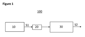
- Figure 1 shows a general block diagram of an exemplary system for compressed sensing 100 comprising a compressive sampling module 10 providing a CS-sampled signal S1, a signal conditioning module 20, and a signal reconstruction module 30 providing a reconstructed signal S2.
- the compressive sampling module 10 may include a sensor that generates an analogue version of a certain sensed signal and said signal is sampled according to current state of the art CS techniques (below Nyquist sampling rate) so that a CS-sampled version S1 of the sensed signal is provided to the next signal conditioning, transmission and/or reconstruction stages.
- the compressive sampling module 10 may trigger or activate a sensor according to current state of the art CS techniques (below Nyquist sampling rate) so that said sensor directly generates a CS-sampled version S1 of the sensed signal.
- the signal conditioning module 20 may comprise an analogue to digital converter and/or any other element for conditioning of the CS-sampled signal S1 to a transmission means.
- the signal reconstruction module 30 is adapted to receive information concerning of the CS-sampled signal S1 and process said CS samples in order to generate a reconstructed signal S2, which is an approximation of the original sensed analogue signal.
- the system for compressed sensing 100 may be an ECG, EEG, EMG or a Pulseoxymeter system.
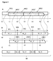
- Figure 2 shows a first exemplary method for calculating or reconstructing an approximation of the original sensed signal using reconstruction windows according to the invention.
- the signal reconstruction module 30 is configured to receive the CS-sampled signal S1 and calculate with that information the reconstructed signal S2.
- the signal reconstruction module 30 is configured to receive a number M of samples of the CS-sampled signal S1, calculate a number N of sparse coefficients using a reconstruction algorithm (e.g. BPDN, OMP, NIHT, etc.) and obtain a number of N values of the reconstructed signal S2 by applying a linear transform to said calculated N sparse coefficients.
- a reconstruction algorithm e.g. BPDN, OMP, NIHT, etc.
- the signal reconstruction module 30 is able to calculate a reconstruction window of N samples/coefficients, and from that reconstruction window, a window of N values of the reconstructed signal S2.
- the linear transform applied to the N sparse coefficients is a Gabor transform.
- the linear transform is a Discrete Cosine Transform (DCT).
- the signal reconstruction module 30 is configured to receive and allocate a first group of measurement windows MS1 to MSi, each comprising a number M of samples, and to calculate, from said first group of measurement windows, a first plurality or group of reconstruction windows W1 to Wi, each comprising a number N of sparse coefficients SC _ i . Also according to an exemplary embodiment of the invention, the signal reconstruction module 30 is configured to receive and allocate a second group of measurement windows c, each comprising a number M of samples, and to calculate, from said second group of measurement windows, a second plurality or group of reconstruction windows OW1 to OWi, each comprising a number N of sparse coefficients SC_i'.
- the first and second group of measurement windows are allocated so that each measurement window of the second group MS1' to MSi' contains a certain number of samples that overlap with two subsequent measurement windows of the first group MS1 to MSi.
- the measurement samples of the first measurement window MS1 of the first group contains M samples received in a first time period, e.g. from time t0 to time t2, while the measurement samples of the first measurement window MS1' of the second group contains M samples received in a second time period, e.g. from time t1 to time t3, then the measurement samples of the second measurement window MS2 of the first group contains M samples received in a third time period, e.g. from time t2 to time t4, and so on.
- the signal reconstruction module 30 is configured to receive samples and allocate those samples to measurement windows according to an overlapping sliding window approach, so that some windows overlap with the content of two other windows.
- the measurement windows of the first and second group have the same sample size M and time period length.
- the measurement windows of the second group MS1' to MSi' are allocated to start at time points, e.g. t1, t3 and t5, which are delayed with respect to the allocation of the starting points, e.g. t0, t2 and t4, of the measurement windows of the first group MS1 to MSi.
- said delay is half the value of the measurement window sample size M/2 or half the time period length of the measurement windows.
- the signal reconstruction module 30 is configured for allocating the samples of the measurement windows of the first and second group in an alternative manner, that is, first allocating the samples of the first widow MS1 of the first group, then allocating the samples of the first window MS1' of the second group, then allocating the samples of the second widow MS2 of the first group, then allocating the samples of the second window MS2' of the second group, and so on.
- the resulting reconstruction windows of the second group OW1 to OWi will be an overlapped version of the resulting reconstruction windows of the first group W1 to Wi, as shown in Figure 2B .
- the signal reconstruction module 30 is also configured for calculating the reconstruction windows of the first and second group in an alternative manner, that is, first calculating the first reconstruction window W1 of the first group, then calculating the first reconstruction window OW1 of the second group, then calculating the second reconstruction window W2 of the first group, then calculating the second reconstruction window OW2 of the second group, and so on.
- the reconstruction windows of the first and second group W1 to Wi and OW1 to OWi have the same sample size N and time period length.
- the reconstruction windows of the second group OW1 to OWi are calculated to start at time points, e.g. t1, t3 and t5, which are delayed with respect to the calculated starting time points, e.g. t0, t2 and t4, of the reconstruction windows of the first group W1 to Wi.
- said delay is half the value of the measurement window sample size N/2 or half the time period length of the reconstructed windows.
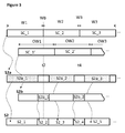
- the signal reconstruction module 30 is configured for calculating the values S2_n of the reconstructed signal S2, as shown in Figure 2C and more detailed in Figure 3 .
- the signal reconstruction module 30 is configured for applying a linear transform to the reconstruction windows of the first group W1 to Wi in order to obtain a first reconstructed signal S2a, and applying a linear transform to the reconstruction windows of the second group OW1 to OWi in order to obtain a second reconstructed signal S2b.
- the signal reconstruction module 30 is also configured for calculating the values S2_n of the reconstructed signal S2 so that a first group of segments, e.g. S2_1, S2_3, S2_5 to S2_(2n+1), contain values derived from the first reconstructed signal S2a and a second group of segments, e.g. S2_2, S2_4 to S2_2n, contain values derived from the second reconstructed signal S2b.
- the values S2_n of the reconstructed signal S2 are the values from the first reconstructed signal S2a, but in which a certain number of values, e.g. values that lie close to a time point t2, t4 in which there is a window boundary WB of the first group of reconstruction windows W1 to Wi, are substituted by values, e.g. S2b_1, S2b_2, of the second reconstructed signal S2b that lie close or adjacent to said window boundary WB time points t2, t4.
- said number of substituted values that lie close or adjacent to a window boundary WB time point t2, t4 of the first group of reconstruction windows is N/2.
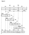
- Figure 4 shows schematically a method for generating the reconstructed signal S2 according to an exemplary embodiment.
- a first segment S2a1 of the reconstructed signal (derived from window W1 of the first group of reconstruction windows) is calculated, then at a second processing point P2, a second segment S2b1 of the reconstructed signal (derived from window OW1 of the second group of reconstruction windows) is calculated and a value/sample replacement process is performed so that only some values or samples V1 and V2 are kept, and the others are discarded;
- a subsequent processing point P3 a third segment S2a2 of the reconstructed signal (derived from window W2 of the first group of reconstruction windows) is calculated and a further value replacement process is performed so that some of the values V2 of the second segment are substituted by values V3 of the third segment (or vice versa);
- a subsequent processing point P4 a fourth segment S2b2 of the reconstructed signal (derived from window OW2 of the second group of reconstruction windows) is calculated and
- the first reconstructed signal segment S2_1 contains values from the first calculated segment S2a1
- the second reconstructed signal segment S2_2 contains values from the second calculated segment S2b1
- the third reconstructed signal segment S2_3 contains values from the third calculated segment S2a2
- the fourth reconstructed signal segment S2_4 contains values from the fourth calculated segment S2b2, and so on.
- the value replacement process at each processing point P1 to Pn may be done in different ways.
- the value replacement process is done by: retaining N/2 samples from the previously reconstructed signal segment and replacing the first N/4 samples of the current reconstructed signal segment with the corresponding values from the previously reconstructed signal segment (samples from N/2 to 3N/4 of the previously reconstructed window).
- the proposed method for compressed sensing advantageously reduces latency, i.e. the time the system needs to provide information about the reconstructed signal, which depends on the amount of time taken from the moment the first measurement sample is acquired to the moment the first reconstructed signal sample is output.
- latency i.e. the time the system needs to provide information about the reconstructed signal, which depends on the amount of time taken from the moment the first measurement sample is acquired to the moment the first reconstructed signal sample is output.
- M samples are acquired before the reconstruction process could be applied to generate N samples. Therefore if one needs to observe the 5N/4 th sample with a reconstruction window size of N, one has to wait until 2M measurement samples are acquired, because the 5N/4 th sample falls in the second reconstruction window.
- an overlapped window technique is applied according to an embodiment of the present invention, the 5N/4 th sample is available after acquiring only 3M/2 samples, due to the fact that the 5N/4 th sample belongs to an overlapped window.
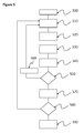
- Figure 5 shows a general flow diagram of a method for calculating the reconstructed signal S2 according to an exemplary embodiment.
- an initialization parameter is set to true, e.g. 'first window' equals to 'true'.
- a measurement window MS1 to MSi or MS1' to Msi' is received and allocated according to embodiments of the invention and in connection with step 540; in a subsequent step 520 a corresponding reconstruction windows W1 to Wi or OW1 to OWi is calculated according to embodiments of the invention, e.g.
- a corresponding first or a second version of the reconstructed signal S1a, S1b is calculated according to embodiments of the invention; in a subsequent step 540 the measurement window is slid by a certain number of samples such that there is overlapping.
- the measurement window is slid by M/2 samples or half the size of the measurement windows; in a subsequent step 550 it is checked whether the initialization parameter is equal to 'true' and in that case the method goes to step 560 in which the initialization condition parameter is set to 'false' and then back to step 510 in order to receive and allocate a new measurement window; if the initialization condition is not met then the method follows with step 570 in which values from the previous reconstructed signal segment are substituted by values of the newly reconstructed signal segment, or vice versa (as for example shown in Figure 4 ).
- the replacement process is as follows: retain N/2 samples from the previously reconstructed signal window and replace the first N/4 samples of the current reconstructed signal window with the corresponding values from the previously reconstructed signal window (samples from N/2 to 3N/4 of the previously reconstructed window).
- a subsequent step 580 it is checked whether there are more measurement samples to process and in that case the method goes to previous step 510; if no more measurement samples are available or there is an indication that the reconstruction process shall be finished, then the method finishes in step 590 providing the reconstructed signal S2.
- the reconstruction method performs repeated l 1,2 -minimization followed by inverse DCT based reconstruction on windows of window length N, with a N/2 sample shift between two consecutive reconstructions.
- N window length
- the reconstruction method performs repeated l 1,2 -minimization followed by inverse DCT based reconstruction on windows of window length N, with a N/2 sample shift between two consecutive reconstructions.
- the reconstruction quality achieved with overlapping reconstruction windows of size N corresponds to the quality obtained using the traditional approach with windows of double the size 2N.
- the proposed approach according to an exemplary embodiment reduces the computational complexity of the reconstruction process, compared to a reconstruction window twice as long, by a factor of 2.
- the proposed algorithm advantageously circumvents the problem of poor reconstruction quality, particularly at the boundaries of the windows, at higher compression ratios for shorter windows, without having to resort of longer window sizes thereby reducing reconstruction complexity and latency.
- PPG photoplethysmogram
- the reconstruction accuracy of the proposed algorithm according to an exemplary embodiment of the invention approaches that of a traditional reconstruction technique with longer reconstruction windows but with a significantly reduced CPU execution time at higher compression ratios.
- Figure 8 shows a comparison table of the CPU time required for the reconstruction of an original signal, e.g. a PPG signal, and the Signal to Noise and Distortion ratio (SNDR) indicating the quality of the original signal reconstruction for a CS compression ratio of 10 and different reconstruction window sizes, between a state of the art reconstruction algorithm and an exemplary reconstruction algorithm (Overlapped Window), using DCT as sparsifying basis for reconstruction, implementing the method according to an exemplary embodiment of the invention.
- SNDR Signal to Noise and Distortion ratio
- Table 1 provides a more detailed implementation of an exemplary algorithm for reconstructing a signal S2 in a compressed sensing system according to an exemplary embodiment of the invention.
Landscapes
- Engineering & Computer Science (AREA)
- Theoretical Computer Science (AREA)
- Compression, Expansion, Code Conversion, And Decoders (AREA)
Abstract
The invention relates to a system (100) for compressed sensing comprising: a compressive sampling module (10) configured for providing a CS-sampled signal (S1) and a signal reconstruction module (30) configured for receiving and allocating a first plurality of measurement windows (MS1 to MSi) comprising a number of samples from the CS-sampled signal, calculating a corresponding first plurality of reconstruction windows (W1 to Wi) based on said first plurality of measurement windows and calculating a first version of a reconstructed signal (S2a) based on said first plurality of reconstruction windows. The signal reconstruction module (30) is also configured to allocate a second plurality measurement windows (MS1' to MSi') overlapping in content with said first plurality of measurement windows (MS1 to MSi), calculate a second plurality of reconstruction windows (OW1 to OWi) based on said second plurality of measurement windows, calculate a second version (S2b) of the reconstructed signal based on said second plurality of reconstructed windows and generate a reconstructed signal (S2) based on values from said first version (S2a) and said second version (S2b) of the reconstructed signal.
Description
- The present description relates generally to signal acquisition systems and more specifically to systems and methods for compressed sensing.
- Compressed sensing or compressive sampling (CS) is an emerging signal processing technique that asserts that certain signals can be recovered faithfully from far fewer number of samples or measurements. CS relies on the underlying structure of the signal which is expressed terms of its 'sparsity' and the 'incoherence' which is related to the sampling scheme (see for example " An Introduction to compressive sampling", E. J. Candès et al., IEEE Signal Processing Magazine, vol. 25, pp 21-30, Mar. 2008).
- Known state-of-the-art biosignal acquisition systems using, for example, the techniques described in " Compressed Sensing System Considerations for ECG and EMG Wireless Biosensors", A.M.R. Dixon et al., IEEE Transactions on Biomedical Circuits and Systems, vol. 6, No.2, April 2012, require, for the reconstruction of an approximation of the original sampled signals, long reconstruction windows of samples N to induce sufficient signal sparsity and optimize reconstruction quality (reduce reconstruction error). On the other hand, the processing of long reconstruction windows of samples N increases latency and requires significant computational complexity, e.g. up to O(N3), since the computational complexity of the reconstruction depends on the reconstruction window sample size N, which makes current techniques inadequate for embedded applications.
- Therefore there exists a link between the CS reconstruction window sample length, signal reconstruction quality and processing complexity. This trade-off is also apparent from the paper " An ultra low power pulse oximeter sensor based on compressed sensing", P.K. Baheti et al., Body Sensor Networks 2009, pp 144-148, Berkelei, USA 2009.
- There is a motivation to improve current state of the art compressed sensing systems and methods in order to reduce signal reconstruction complexity and/or power and/or increase signal reconstruction quality and/or a trade-off thereof.
- According to one aspect of the present invention, a new and improved method and system for compressed sensing is provided.
- According to an exemplary embodiment, the system and method for compressed sensing advantageously improves the accuracy or quality of the reconstruction of the original sampled signal for a predefined reconstruction window sample size, therefore improving the trade-off between the reconstruction window sample size and the signal reconstruction accuracy. According to an exemplary embodiment, the system and method for compressed sensing advantageously improves the signal reconstruction accuracy using shorter reconstruction window sizes.
- According to an exemplary embodiment, the system and method for compressed sensing advantageously reduces signal reconstruction latency for a predefined reconstruction window sample size, therefore improving the trade-off between the reconstruction window sample size and signal reconstruction latency. According to an exemplary embodiment, the system and method for compressed sensing advantageously achieves signal reconstruction accuracy comparable to that achieved by state of the art techniques using longer reconstruction window sizes, but at decreased latency.
- According to an exemplary embodiment, the system and method for compressed sensing advantageously reduces signal reconstruction processing complexity for achieving a predefined signal reconstruction accuracy, therefore improving the trade-off between signal reconstruction complexity and signal reconstruction accuracy. According to an exemplary embodiment, the system and method for compressed sensing advantageously provides increased reconstruction quality without significantly increasing computational complexity.
- According to an exemplary embodiment, there is provided a system for compressed sensing comprising: a compressive sampling module configured for providing a CS-sampled signal; and a signal reconstruction module configured for receiving and allocating a first plurality of measurement windows comprising a number of samples from the CS-sampled signal, calculating a corresponding first plurality of reconstruction windows based on said first plurality of measurement windows and calculating a first version of a reconstructed signal based on said first plurality of reconstruction windows; and further configured to allocate a second plurality measurement windows overlapping in content with said first plurality of measurement windows, calculate a second plurality of reconstruction windows based on said second plurality of measurement windows, calculate a second version of the reconstructed signal based on said second plurality of reconstructed windows and generate a reconstructed signal based on values from said first version and said second version of the reconstructed signal.
- According to an exemplary embodiment, the segment values taken from the second version of the reconstructed signal are segment values corresponding to a window boundary of the first plurality of reconstruction windows.
- According to an exemplary embodiment, the signal reconstruction module is configured for iteratively calculating a first segment from the first version of the reconstructed signal and then a subsequent segment from the second version of the reconstructed signal and for substituting values from the first segment into the subsequent segment or vice versa.
- According to an exemplary embodiment, the signal reconstruction module is configured for retaining N/2 sample values from the previously reconstructed signal segment and replacing the first N/4 sample values of the current reconstructed signal segment with the corresponding values from the previously reconstructed signal segment.
- According to an exemplary embodiment, the linear transform used for calculating said first and second version of the reconstructed signal is a discrete cosine transform.
- According to an exemplary embodiment, the system and method for compressed sensing is advantageously used for low power and efficient acquisition, processing and/or monitoring of biosignals such as, for example electrocardiogram (ECG), electroencephalogram (EEG), electromyogram (EMG) and/or photoplethysmogram (PPG) signals.
- According to an exemplary embodiment, the proposed method for compressed sensing advantageously improves reconstruction accuracy for shorter reconstruction windows. According to an embodiment, the proposed method for compressed sensing is able to achieve higher reconstruction accuracy for shorter window sizes compared to traditional state of the art approaches.
- According to an exemplary embodiment, the proposed method for compressed sensing advantageously eliminates reconstruction artifacts at the boundaries of the reconstruction windows, which are inherent to the traditional signal reconstruction approaches.
- The invention also relates to an electronic device comprising a system for compressed sensing according to embodiments herein described.
- Further, the invention also relates to a method for reconstructing a signal in a compressed sensing system, the method comprising: receiving and allocating a first plurality of measurement windows comprising a number of samples from a CS-sampled signal; calculating a corresponding first plurality of reconstruction windows based on said first plurality of measurement windows; calculating a first version of a reconstructed signal based on said first plurality of reconstruction windows; allocating a second plurality measurement windows overlapping in content with said first plurality of measurement windows; calculating a second plurality of reconstruction windows based on said second plurality of measurement windows; calculating a second version of the reconstructed signal based on said second plurality of reconstructed windows; and generating the reconstructed signal based on values from said first version and said second version of the reconstructed signal.
- According to an exemplary embodiment, allocating the second plurality measurement windows overlapping in content with said first plurality of measurement windows comprises sliding the measurement windows of the second plurality to a position in which there are samples from two measurement windows of the first plurality.
- The invention also relates to a computer program product comprising computer program code means adapted to calculate a reconstructed signal in a compressed sensing system, according to embodiments of the method herein described, when said program is run on a computer.
- Further, the invention relates to a computer readable storage medium comprising the herein described computer program calculating a reconstructed signal in a compressed sensing system.
- The above and other aspects of the system according to the present description will be shown and explained with reference to the non-restrictive example embodiments described hereinafter.
-
Figure 1 shows a general block diagram of an exemplary system for compressed sensing. -
Figure 2 shows a first exemplary method for calculating a reconstructed signal using measurement and reconstruction windows according to the invention. -
Figure 3 shows a second exemplary method for calculating a reconstructed signal derived from calculated first and second reconstruction signals according to the invention. -
Figure 4 shows a third exemplary method for calculating a reconstructed signal derived from calculated first and second reconstruction signals according to the invention. -
Figure 5 shows a general flow diagram of an exemplary method for calculating a reconstructed signal according to the invention. -
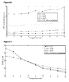
Figure 6 shows a comparison graph of the CPU time required for the reconstruction of the original CS-sampled signal for different values of compression ratios and reconstruction window sizes, between a state of the art reconstruction algorithm and an exemplary reconstruction algorithm implementing the method according to the invention. -
Figure 7 shows a comparison graph of the Signal to Noise and Distortion ratio (SNDR) indicating the quality of the original CS-sampled signal reconstruction for different values of compression ratios and reconstruction window sizes, between a state of the art reconstruction algorithm and an exemplary reconstruction algorithm implementing the method according to the invention. -
Figure 8 shows a comparison table of the CPU time required for the reconstruction of the original CS-sampled signal and the Signal to Noise and Distortion ratio (SNDR) indicating the quality of the original CS-sampled signal reconstruction for a compression ratio of 10 and different reconstruction window sizes, between a state of the art reconstruction algorithm and an exemplary reconstruction algorithm implementing the method according to the invention. - In the following, in the description of exemplary embodiments, various features may be grouped together in a single embodiment, figure, or description thereof for the purpose of streamlining the disclosure and aiding in the understanding of one or more of the various inventive aspects. This is however not to be interpreted as the invention requiring more features than the ones expressly recited in the main claim. Furthermore, combinations of features of different embodiments are meant to be within the scope of the invention, as would be clearly understood by those skilled in the art. Additionally, in other instances, well-known methods, structures and techniques have not been shown in detail in order not to obscure the conciseness of the description.
-
Figure 1 shows a general block diagram of an exemplary system forcompressed sensing 100 comprising acompressive sampling module 10 providing a CS-sampled signal S1, asignal conditioning module 20, and asignal reconstruction module 30 providing a reconstructed signal S2. Thecompressive sampling module 10 may include a sensor that generates an analogue version of a certain sensed signal and said signal is sampled according to current state of the art CS techniques (below Nyquist sampling rate) so that a CS-sampled version S1 of the sensed signal is provided to the next signal conditioning, transmission and/or reconstruction stages. Alternatively, thecompressive sampling module 10 may trigger or activate a sensor according to current state of the art CS techniques (below Nyquist sampling rate) so that said sensor directly generates a CS-sampled version S1 of the sensed signal. Thesignal conditioning module 20 may comprise an analogue to digital converter and/or any other element for conditioning of the CS-sampled signal S1 to a transmission means. Thesignal reconstruction module 30 is adapted to receive information concerning of the CS-sampled signal S1 and process said CS samples in order to generate a reconstructed signal S2, which is an approximation of the original sensed analogue signal. According to exemplary embodiments, the system for compressed sensing 100 according to the invention may be an ECG, EEG, EMG or a Pulseoxymeter system. -
Figure 2 shows a first exemplary method for calculating or reconstructing an approximation of the original sensed signal using reconstruction windows according to the invention. According to an exemplary embodiment, thesignal reconstruction module 30 is configured to receive the CS-sampled signal S1 and calculate with that information the reconstructed signal S2. According to an embodiment, thesignal reconstruction module 30 is configured to receive a number M of samples of the CS-sampled signal S1, calculate a number N of sparse coefficients using a reconstruction algorithm (e.g. BPDN, OMP, NIHT, etc.) and obtain a number of N values of the reconstructed signal S2 by applying a linear transform to said calculated N sparse coefficients. This process is iteratively done for each window of M samples received, which will be called in the text a measurement window. The corresponding window of N sparse coefficients is called in the text a reconstruction window. Therefore, for each measurement window of M samples of the CS-sampled signal S1, thesignal reconstruction module 30 is able to calculate a reconstruction window of N samples/coefficients, and from that reconstruction window, a window of N values of the reconstructed signal S2. According to an embodiment of the invention, the linear transform applied to the N sparse coefficients is a Gabor transform. According to another exemplary embodiment, the linear transform is a Discrete Cosine Transform (DCT). - According to an embodiment of the present invention, and as shown in
Figure 2A , thesignal reconstruction module 30 is configured to receive and allocate a first group of measurement windows MS1 to MSi, each comprising a number M of samples, and to calculate, from said first group of measurement windows, a first plurality or group of reconstruction windows W1 to Wi, each comprising a number N of sparse coefficients SC_i. Also according to an exemplary embodiment of the invention, thesignal reconstruction module 30 is configured to receive and allocate a second group of measurement windows c, each comprising a number M of samples, and to calculate, from said second group of measurement windows, a second plurality or group of reconstruction windows OW1 to OWi, each comprising a number N of sparse coefficients SC_i'. - According to an embodiment, the first and second group of measurement windows are allocated so that each measurement window of the second group MS1' to MSi' contains a certain number of samples that overlap with two subsequent measurement windows of the first group MS1 to MSi. For example, the measurement samples of the first measurement window MS1 of the first group contains M samples received in a first time period, e.g. from time t0 to time t2, while the measurement samples of the first measurement window MS1' of the second group contains M samples received in a second time period, e.g. from time t1 to time t3, then the measurement samples of the second measurement window MS2 of the first group contains M samples received in a third time period, e.g. from time t2 to time t4, and so on. Therefore, the content/samples of the second group of measurement windows MS1' to MSi' overlaps, depending on the selected overlapping time periods, with the content of the first group of measurement windows MS1 to MSi. In other words, according to an exemplary embodiment, the
signal reconstruction module 30 is configured to receive samples and allocate those samples to measurement windows according to an overlapping sliding window approach, so that some windows overlap with the content of two other windows. - According to an exemplary embodiment, the measurement windows of the first and second group have the same sample size M and time period length. According to an exemplary embodiment of the invention, the measurement windows of the second group MS1' to MSi' are allocated to start at time points, e.g. t1, t3 and t5, which are delayed with respect to the allocation of the starting points, e.g. t0, t2 and t4, of the measurement windows of the first group MS1 to MSi. According to an exemplary embodiment, said delay is half the value of the measurement window sample size M/2 or half the time period length of the measurement windows.
- According to an exemplary embodiment, the
signal reconstruction module 30 is configured for allocating the samples of the measurement windows of the first and second group in an alternative manner, that is, first allocating the samples of the first widow MS1 of the first group, then allocating the samples of the first window MS1' of the second group, then allocating the samples of the second widow MS2 of the first group, then allocating the samples of the second window MS2' of the second group, and so on. - In the same sense, and according to an exemplary embodiment of the invention, the resulting reconstruction windows of the second group OW1 to OWi will be an overlapped version of the resulting reconstruction windows of the first group W1 to Wi, as shown in
Figure 2B . - According to an exemplary embodiment, the
signal reconstruction module 30 is also configured for calculating the reconstruction windows of the first and second group in an alternative manner, that is, first calculating the first reconstruction window W1 of the first group, then calculating the first reconstruction window OW1 of the second group, then calculating the second reconstruction window W2 of the first group, then calculating the second reconstruction window OW2 of the second group, and so on. - According to an exemplary embodiment, the reconstruction windows of the first and second group W1 to Wi and OW1 to OWi have the same sample size N and time period length. According to an exemplary embodiment, the reconstruction windows of the second group OW1 to OWi are calculated to start at time points, e.g. t1, t3 and t5, which are delayed with respect to the calculated starting time points, e.g. t0, t2 and t4, of the reconstruction windows of the first group W1 to Wi. According to an exemplary embodiment, said delay is half the value of the measurement window sample size N/2 or half the time period length of the reconstructed windows.
- Also according to an exemplary embodiment the
signal reconstruction module 30 is configured for calculating the values S2_n of the reconstructed signal S2, as shown inFigure 2C and more detailed inFigure 3 . - As shown in
Figure 3 , thesignal reconstruction module 30 is configured for applying a linear transform to the reconstruction windows of the first group W1 to Wi in order to obtain a first reconstructed signal S2a, and applying a linear transform to the reconstruction windows of the second group OW1 to OWi in order to obtain a second reconstructed signal S2b. According to an exemplary embodiment, thesignal reconstruction module 30 is also configured for calculating the values S2_n of the reconstructed signal S2 so that a first group of segments, e.g. S2_1, S2_3, S2_5 to S2_(2n+1), contain values derived from the first reconstructed signal S2a and a second group of segments, e.g. S2_2, S2_4 to S2_2n, contain values derived from the second reconstructed signal S2b. - According to an exemplary embodiment, the values S2_n of the reconstructed signal S2 are the values from the first reconstructed signal S2a, but in which a certain number of values, e.g. values that lie close to a time point t2, t4 in which there is a window boundary WB of the first group of reconstruction windows W1 to Wi, are substituted by values, e.g. S2b_1, S2b_2, of the second reconstructed signal S2b that lie close or adjacent to said window boundary WB time points t2, t4. According to an exemplary embodiment, said number of substituted values that lie close or adjacent to a window boundary WB time point t2, t4 of the first group of reconstruction windows is N/2.
-
Figure 4 shows schematically a method for generating the reconstructed signal S2 according to an exemplary embodiment. At a first processing point P1, a first segment S2a1 of the reconstructed signal (derived from window W1 of the first group of reconstruction windows) is calculated, then at a second processing point P2, a second segment S2b1 of the reconstructed signal (derived from window OW1 of the second group of reconstruction windows) is calculated and a value/sample replacement process is performed so that only some values or samples V1 and V2 are kept, and the others are discarded; at a subsequent processing point P3 a third segment S2a2 of the reconstructed signal (derived from window W2 of the first group of reconstruction windows) is calculated and a further value replacement process is performed so that some of the values V2 of the second segment are substituted by values V3 of the third segment (or vice versa); at a subsequent processing point P4 a fourth segment S2b2 of the reconstructed signal (derived from window OW2 of the second group of reconstruction windows) is calculated and a further value replacement process is performed so that some of the values V3 of the third segment are substituted by values V4 of the fourth segment (or vice versa), and so on. Therefore, according to an exemplary embodiment, the first reconstructed signal segment S2_1 contains values from the first calculated segment S2a1, the second reconstructed signal segment S2_2 contains values from the second calculated segment S2b1, the third reconstructed signal segment S2_3 contains values from the third calculated segment S2a2, the fourth reconstructed signal segment S2_4 contains values from the fourth calculated segment S2b2, and so on. - It is understood that the value replacement process at each processing point P1 to Pn may be done in different ways. According to an exemplary embodiment, the value replacement process is done by: retaining N/2 samples from the previously reconstructed signal segment and replacing the first N/4 samples of the current reconstructed signal segment with the corresponding values from the previously reconstructed signal segment (samples from N/2 to 3N/4 of the previously reconstructed window).
- According to an exemplary embodiment, the proposed method for compressed sensing advantageously reduces latency, i.e. the time the system needs to provide information about the reconstructed signal, which depends on the amount of time taken from the moment the first measurement sample is acquired to the moment the first reconstructed signal sample is output. In conventional sate of the art reconstruction schemes with non-overlapping windows, one needs to wait until M samples are acquired before the reconstruction process could be applied to generate N samples. Therefore if one needs to observe the 5N/4th sample with a reconstruction window size of N, one has to wait until 2M measurement samples are acquired, because the 5N/4th sample falls in the second reconstruction window. In contrast, when an overlapped window technique is applied according to an embodiment of the present invention, the 5N/4th sample is available after acquiring only 3M/2 samples, due to the fact that the 5N/4th sample belongs to an overlapped window.
-
Figure 5 shows a general flow diagram of a method for calculating the reconstructed signal S2 according to an exemplary embodiment. In afirst step 500 an initialization parameter is set to true, e.g. 'first window' equals to 'true'. In a subsequent step 510 a measurement window MS1 to MSi or MS1' to Msi' is received and allocated according to embodiments of the invention and in connection withstep 540; in a subsequent step 520 a corresponding reconstruction windows W1 to Wi or OW1 to OWi is calculated according to embodiments of the invention, e.g. using an inverse DCT; in a subsequent step 530 a corresponding first or a second version of the reconstructed signal S1a, S1b is calculated according to embodiments of the invention; in asubsequent step 540 the measurement window is slid by a certain number of samples such that there is overlapping. According to an exemplary embodiment the measurement window is slid by M/2 samples or half the size of the measurement windows; in asubsequent step 550 it is checked whether the initialization parameter is equal to 'true' and in that case the method goes to step 560 in which the initialization condition parameter is set to 'false' and then back to step 510 in order to receive and allocate a new measurement window; if the initialization condition is not met then the method follows withstep 570 in which values from the previous reconstructed signal segment are substituted by values of the newly reconstructed signal segment, or vice versa (as for example shown inFigure 4 ). According to an embodiment of the invention, the replacement process is as follows: retain N/2 samples from the previously reconstructed signal window and replace the first N/4 samples of the current reconstructed signal window with the corresponding values from the previously reconstructed signal window (samples from N/2 to 3N/4 of the previously reconstructed window). In asubsequent step 580 it is checked whether there are more measurement samples to process and in that case the method goes toprevious step 510; if no more measurement samples are available or there is an indication that the reconstruction process shall be finished, then the method finishes instep 590 providing the reconstructed signal S2. - According to a further exemplary embodiment, the reconstruction method performs repeated ℓ 1,2-minimization followed by inverse DCT based reconstruction on windows of window length N, with a N/2 sample shift between two consecutive reconstructions. Advantageously, according to an exemplary embodiment, to overcome window boundary reconstruction artifacts, only the middle N/2 reconstructed samples are retained and combined with obtained samples from neighboring windows.
- Advantageously, according to an embodiment, the reconstruction quality achieved with overlapping reconstruction windows of size N corresponds to the quality obtained using the traditional approach with windows of double the
size 2N. Also advantageously, the proposed approach according to an exemplary embodiment reduces the computational complexity of the reconstruction process, compared to a reconstruction window twice as long, by a factor of 2. - According to an exemplary embodiment, the proposed algorithm advantageously circumvents the problem of poor reconstruction quality, particularly at the boundaries of the windows, at higher compression ratios for shorter windows, without having to resort of longer window sizes thereby reducing reconstruction complexity and latency.
-
Figure 6 shows a comparison graph of the CPU time required for the reconstruction of an original signal, e.g. a photoplethysmogram (PPG) signal, for different values of CS compression ratios and reconstruction window sizes, between a state of the art reconstruction algorithm and an exemplary reconstruction algorithm, using DCT as sparsifying basis for reconstruction, implementing a method according to the invention (N=512 with overlapping). To compare the complexity of the algorithms, the CPU time required for the execution of the algorithms implemented in MATLAB is measured. This CPU time is measured as the execution time of the algorithm for a given record over 25 runs for different values of compression ratio CR and window sizes along with execution time for the proposed algorithm according to an exemplary embodiment of the invention (for a window size of 512 samples). The average execution time across 20 records is plotted. -
Figure 7 shows a comparison graph of the Signal to Noise and Distortion ratio (SNDR) indicating the quality of the original signal reconstruction, e.g. a PPG signal, for different values of compression ratios and reconstruction window sizes, between a state of the art reconstruction algorithm and an exemplary reconstruction algorithm, using DCT as sparsifying basis for reconstruction, implementing the method according to the invention (N=512 with overlapping). At lower CS compression ratios, the average SNDR is higher for shorter windows. This is due to the presence of motion artifacts in the signal records which tend to reduce the sparsity when longer windows are used. As can be seen, the reconstruction accuracy of the proposed algorithm according to an exemplary embodiment of the invention approaches that of a traditional reconstruction technique with longer reconstruction windows but with a significantly reduced CPU execution time at higher compression ratios. -
Figure 8 shows a comparison table of the CPU time required for the reconstruction of an original signal, e.g. a PPG signal, and the Signal to Noise and Distortion ratio (SNDR) indicating the quality of the original signal reconstruction for a CS compression ratio of 10 and different reconstruction window sizes, between a state of the art reconstruction algorithm and an exemplary reconstruction algorithm (Overlapped Window), using DCT as sparsifying basis for reconstruction, implementing the method according to an exemplary embodiment of the invention. For a compression ratio of 10, the CPU execution time, the average SNDR and the SNDR in the overlapped segments for the traditional reconstruction withwindow sizes window size 512 are shown. It can be seen that the CPU execution time and hence the complexity of the reconstruction is reduced by a factor of 2.4, without significant degradation in reconstruction accuracy. - Table 1 provides a more detailed implementation of an exemplary algorithm for reconstructing a signal S2 in a compressed sensing system according to an exemplary embodiment of the invention.
- It will be clear for a person skilled in the art that the methods and techniques of the embodiments herein described may be implemented by hardware and/or software means in a processing unit and/or executed by a computer or processor, for example carrying out the steps of the methods according to exemplary embodiments of the invention. They also may take the form of a program or computer executable code or instructions stored in a computer-readable medium or computer readable memory, such us, but not limited to a hard drive, ROM, RAM, CD-ROM, etc.
TABLE 1: Overlapped window reconstruction algorithm Definition: Y : Measurement vector obtained by random sampling Xr : Reconstructed signal vector Y0v1 : Overlapped measurement vector Ψ : DCT basis matrix Φ : Random sampling matrix N : Length of the signal window CR: Compression ratio numWin : Total number of windows to be reconstructed Algorithm: procedure csDecode (Y, Φ, Ψ -1) Compute S by solving min ½∥Y - ΦΨ-1S∥2 2 + τ∥S∥1 Compute X = Ψ-1S return X end procedure loop for all i = 1 : numWin 1. Xr 1 ← csDecode(Y, Φ, Ψ-1) 2. Xr i+1 ← csDecode(Yi+1, Φ, Ψ-1) 3. 
4. 
5. Xrovl ← csDecode(Yovl, Φ, Ψ-1) 6. 
7. 
end loop
Claims (11)
- A system (100) for compressed sensing comprising:a compressive sampling module (10) configured for providing a CS-sampled signal (S1); anda signal reconstruction module (30) configured for receiving and allocating a first plurality of measurement windows (MS1 to MSi) comprising a number of samples from the CS-sampled signal, calculating a corresponding first plurality of reconstruction windows (W1 to Wi) based on said first plurality of measurement windows and calculating a first version (S2a) of a reconstructed signal based on said first plurality of reconstruction windows;
characterized in thatthe signal reconstruction module (30) is further configured to allocate a second plurality measurement windows (MS1' to MSi') overlapping in content with said first plurality of measurement windows, calculate a second plurality of reconstruction windows (OW1 to OWi) based on said second plurality of measurement windows, calculate a second version (S2b) of the reconstructed signal based on said second plurality of reconstructed windows and generate a reconstructed signal (S2) based on values from said first version (S2a) and said second version (S2b) of the reconstructed signal. - A system (100) for compressed sensing according to claim 1 wherein the signal reconstruction module (30) is configured to generate the reconstructed signal (S2) by replacing a number of values from the first reconstructed signal version (S2a) with a number of values (S2b_1, S2b_2) from the second reconstructed signal version (S2b), said values (S2b_1, S2b_2) from the second reconstructed signal version (S2b) corresponding to values lying adjacent to a window boundary (WB) of the first plurality of reconstruction windows (W1 to Wi).
- A system (100) for compressed sensing according to any of the previous claims wherein the signal reconstruction module (30) is configured for iteratively calculating segments (S2a1, S2a2) from the first version of the reconstructed signal (S2a) and segments (S2b1, S2b2) from the second version of the reconstructed signal (S2b) in an alternate manner and for substituting values (V1, V2, V3, V4) between two subsequent segments.
- A system (100) for compressed sensing according to claim 3 wherein the signal reconstruction module (30) is configured for calculating said reconstructed signal segments (S2a1, S2b1, S2a2, S2b2) with a segment size of N samples and for retaining N/2 sample values from a previously calculated reconstructed signal segment and replacing the first N/4 sample values of a new reconstructed signal segment with the corresponding values from the previously reconstructed signal segment.
- A system (100) for compressed sensing according to any of the previous claims wherein the linear transform used for calculating said first (S2a) and second version (S2b) of the reconstructed signal is a discrete cosine transform (DCT).
- A system (100) for compressed sensing according to any of the previous claims wherein the CS-sampled signal (S1) is an ECG, EEG, EMG or a PPG biosignal.
- An electronic device or device network comprising a system (100) for compressed sensing according to any of claims 1 to 6.
- A method for reconstructing a signal (S2) in a compressed sensing system (100), the method comprising:receiving and allocating a first plurality of measurement windows (MS1 to MSi) comprising a number of samples from a CS-sampled signal (S1);calculating a corresponding first plurality of reconstruction windows (W1 to Wi) based on said first plurality of measurement windows; andcalculating a first version of a reconstructed signal (S2a) based on said first plurality of reconstruction windows;
characterized by furtherallocating a second plurality measurement windows (MS1' to MSi') overlapping in content with said first plurality of measurement windows;calculating a second plurality of reconstruction windows (OW1 to OWi) based on said second plurality of measurement windows;calculating a second version (S2b) of the reconstructed signal based on said second plurality of reconstructed windows; andgenerating the reconstructed signal (S2) based on values from said first version (S2a) and said second version (S2b) of the reconstructed signal. - A method for reconstructing a signal (S2) in a compressed sensing system (100) according to claim 8, wherein allocating a second plurality measurement windows (MS1' to MSi') overlapping in content with said first plurality of measurement windows comprises sliding the measurement windows of the second plurality to a position in which there are samples from two subsequent measurement windows of the first plurality.
- A computer program product comprising computer program code means adapted to calculate a reconstructed signal (S2) in a compressed sensing system (100) according to the method of claims 8 or 9 when said program is run on a computer.
- A computer readable storage medium comprising a computer program according to claim 10.
Priority Applications (2)
| Application Number | Priority Date | Filing Date | Title |
|---|---|---|---|
| EP15154815.3A EP3012978A1 (en) | 2014-10-21 | 2015-02-12 | System and method for compressed sensing . |
| US14/886,537 US10284224B2 (en) | 2014-10-21 | 2015-10-19 | System and method for compressed sensing |
Applications Claiming Priority (2)
| Application Number | Priority Date | Filing Date | Title |
|---|---|---|---|
| EP14189794 | 2014-10-21 | ||
| EP15154815.3A EP3012978A1 (en) | 2014-10-21 | 2015-02-12 | System and method for compressed sensing . |
Publications (1)
| Publication Number | Publication Date |
|---|---|
| EP3012978A1 true EP3012978A1 (en) | 2016-04-27 |
Family
ID=51743378
Family Applications (1)
| Application Number | Title | Priority Date | Filing Date |
|---|---|---|---|
| EP15154815.3A Withdrawn EP3012978A1 (en) | 2014-10-21 | 2015-02-12 | System and method for compressed sensing . |
Country Status (2)
| Country | Link |
|---|---|
| US (1) | US10284224B2 (en) |
| EP (1) | EP3012978A1 (en) |
Families Citing this family (2)
| Publication number | Priority date | Publication date | Assignee | Title |
|---|---|---|---|---|
| CN115968532B (en) * | 2020-09-28 | 2026-01-27 | 伊顿智能动力有限公司 | Efficient codec for electrical signals |
| US11431350B1 (en) * | 2021-02-05 | 2022-08-30 | Cox Communications, Inc. | Lossy statistical data compression |
Citations (1)
| Publication number | Priority date | Publication date | Assignee | Title |
|---|---|---|---|---|
| US20130002715A1 (en) * | 2011-06-28 | 2013-01-03 | Tidman James M | Image Sequence Reconstruction based on Overlapping Measurement Subsets |
Family Cites Families (2)
| Publication number | Priority date | Publication date | Assignee | Title |
|---|---|---|---|---|
| US9075446B2 (en) * | 2010-03-15 | 2015-07-07 | Qualcomm Incorporated | Method and apparatus for processing and reconstructing data |
| US9325947B2 (en) | 2011-06-28 | 2016-04-26 | Inview Technology Corporation | High-speed event detection using a compressive-sensing hyperspectral-imaging architecture |
-
2015
- 2015-02-12 EP EP15154815.3A patent/EP3012978A1/en not_active Withdrawn
- 2015-10-19 US US14/886,537 patent/US10284224B2/en active Active
Patent Citations (1)
| Publication number | Priority date | Publication date | Assignee | Title |
|---|---|---|---|---|
| US20130002715A1 (en) * | 2011-06-28 | 2013-01-03 | Tidman James M | Image Sequence Reconstruction based on Overlapping Measurement Subsets |
Non-Patent Citations (4)
| Title |
|---|
| A.M.R. DIXON ET AL.: "Compressed Sensing System Considerations for ECG and EMG Wireless Biosensors", IEEE TRANSACTIONS ON BIOMEDICAL CIRCUITS AND SYSTEMS, vol. 6, no. 2, April 2012 (2012-04-01) |
| E. J. CANDBS ET AL.: "An Introduction to compressive sampling", IEEE SIGNAL PROCESSING MAGAZINE, vol. 25, March 2008 (2008-03-01), pages 21 - 30 |
| LE THANH TAN ET AL: "A novel and efficient mixed-signal compressed sensing for wide-band cognitive radio", 2010 INTERNATIONAL FORUM ON STRATEGIC TECHNOLOGY (IFOST 2010) : ULSAN, SOUTH KOREA, 13 - 15 OCTOBER 2010, IEEE, PISCATAWAY, NJ, USA, 13 October 2010 (2010-10-13), pages 27 - 32, XP031835709, ISBN: 978-1-4244-9038-7 * |
| P.K. BAHETI ET AL.: "An ultra low power pulse oximeter sensor based on compressed sensing", BODY SENSOR NETWORKS, 2009, pages 144 - 148 |
Also Published As
| Publication number | Publication date |
|---|---|
| US20160112063A1 (en) | 2016-04-21 |
| US10284224B2 (en) | 2019-05-07 |
Similar Documents
| Publication | Publication Date | Title |
|---|---|---|
| EP3028629A1 (en) | System and method for heart rate detection | |
| US20120071730A1 (en) | Adaptive Processing of Ambulatory Electrocardiogram Signals | |
| CN105741305A (en) | Method and system for filtering electromyographical interference based on stationary wavelet transformation | |
| CN101554325B (en) | Method for extracting fetal electrocardiograms (FECG) by separation | |
| EP2430975A1 (en) | Principal component analysis or independent component analysis applied to ambulatory electrocardiogram signals | |
| CN103560795B (en) | A kind of compression method of electrocardiosignal, transmission method, reconstructing method and device | |
| KR20140139564A (en) | Systems and methods for ecg monitoring | |
| CN115828056B (en) | Electrocardiogram characteristic signal extraction method and terminal | |
| Singh et al. | Block sparsity‐based joint compressed sensing recovery of multi‐channel ECG signals | |
| Ansari-Ram et al. | ECG signal compression using compressed sensing with nonuniform binary matrices | |
| Pamula et al. | Computationally-efficient compressive sampling for low-power pulseoximeter system | |
| Nasimi et al. | Exploiting similar prior knowledge for compressing ECG signals | |
| US11806155B2 (en) | System and method for QRS complex detection in compressively sensed electrocardiogram data | |
| US10284224B2 (en) | System and method for compressed sensing | |
| Kumar Jha et al. | Diagnostic quality assured ECG signal compression with selection of appropriate mother wavelet for minimal distortion | |
| Raj et al. | ECG signal denoising using undecimated wavelet transform | |
| Eftekharifar et al. | Block sparse multi‐lead ECG compression exploiting between‐lead collaboration | |
| Torres et al. | Heal-T: an efficient PPG-based heart-rate and IBI estimation method during physical exercise | |
| Majumdar et al. | Combining sparsity with rank-deficiency for energy efficient EEG sensing and transmission over Wireless Body Area Network | |
| CN114098656A (en) | Signal noise reduction method and system based on empirical mode decomposition and bit plane conversion | |
| JPH1049791A (en) | Time series signal processing method and apparatus | |
| KR101856781B1 (en) | Method and apparatus for transmitting/receiving bio-medical signals | |
| Vega-Martínez et al. | Wavelet packet based algorithm for QRS region detection and R/S wave identification | |
| Fira et al. | On projection matrices and dictionaries in ECG compressive sensing-A comparative study | |
| Aneesh et al. | Two-dimensional ecg signal compression based on region of interest using pca |
Legal Events
| Date | Code | Title | Description |
|---|---|---|---|
| PUAI | Public reference made under article 153(3) epc to a published international application that has entered the european phase |
Free format text: ORIGINAL CODE: 0009012 |
|
| AK | Designated contracting states |
Kind code of ref document: A1 Designated state(s): AL AT BE BG CH CY CZ DE DK EE ES FI FR GB GR HR HU IE IS IT LI LT LU LV MC MK MT NL NO PL PT RO RS SE SI SK SM TR |
|
| AX | Request for extension of the european patent |
Extension state: BA ME |
|
| STAA | Information on the status of an ep patent application or granted ep patent |
Free format text: STATUS: THE APPLICATION IS DEEMED TO BE WITHDRAWN |
|
| 18D | Application deemed to be withdrawn |
Effective date: 20161028 |