EP3012937A1 - Control system for renewable energy power generation facilities, method for controlling same, and renewable energy power generation system - Google Patents
Control system for renewable energy power generation facilities, method for controlling same, and renewable energy power generation system Download PDFInfo
- Publication number
- EP3012937A1 EP3012937A1 EP13887235.3A EP13887235A EP3012937A1 EP 3012937 A1 EP3012937 A1 EP 3012937A1 EP 13887235 A EP13887235 A EP 13887235A EP 3012937 A1 EP3012937 A1 EP 3012937A1
- Authority
- EP
- European Patent Office
- Prior art keywords
- power generation
- generation equipment
- renewable energy
- output
- energy power
- Prior art date
- Legal status (The legal status is an assumption and is not a legal conclusion. Google has not performed a legal analysis and makes no representation as to the accuracy of the status listed.)
- Granted
Links
- 238000010248 power generation Methods 0.000 title claims abstract description 322
- 238000000034 method Methods 0.000 title claims description 20
- 238000004364 calculation method Methods 0.000 claims description 44
- 238000005259 measurement Methods 0.000 claims description 20
- 238000004891 communication Methods 0.000 claims description 17
- 238000012545 processing Methods 0.000 claims description 11
- 238000013500 data storage Methods 0.000 claims description 9
- 230000008569 process Effects 0.000 claims description 4
- 230000001629 suppression Effects 0.000 abstract description 10
- 230000014509 gene expression Effects 0.000 description 37
- 230000008859 change Effects 0.000 description 11
- 238000010586 diagram Methods 0.000 description 11
- 230000005540 biological transmission Effects 0.000 description 5
- 230000003247 decreasing effect Effects 0.000 description 5
- 230000000694 effects Effects 0.000 description 5
- 238000012423 maintenance Methods 0.000 description 5
- 230000004044 response Effects 0.000 description 4
- 230000003111 delayed effect Effects 0.000 description 3
- 238000001514 detection method Methods 0.000 description 3
- 238000006243 chemical reaction Methods 0.000 description 2
- 238000012937 correction Methods 0.000 description 2
- 230000009467 reduction Effects 0.000 description 2
- 238000003916 acid precipitation Methods 0.000 description 1
- 238000007792 addition Methods 0.000 description 1
- 238000012217 deletion Methods 0.000 description 1
- 230000037430 deletion Effects 0.000 description 1
- 230000007613 environmental effect Effects 0.000 description 1
- 238000009499 grossing Methods 0.000 description 1
- 238000012986 modification Methods 0.000 description 1
- 230000004048 modification Effects 0.000 description 1
- 230000006641 stabilisation Effects 0.000 description 1
- 238000011105 stabilization Methods 0.000 description 1
- 238000006467 substitution reaction Methods 0.000 description 1
- 238000010792 warming Methods 0.000 description 1
Images


Classifications
-
- H—ELECTRICITY
- H02—GENERATION; CONVERSION OR DISTRIBUTION OF ELECTRIC POWER
- H02J—CIRCUIT ARRANGEMENTS OR SYSTEMS FOR SUPPLYING OR DISTRIBUTING ELECTRIC POWER; SYSTEMS FOR STORING ELECTRIC ENERGY
- H02J3/00—Circuit arrangements for ac mains or ac distribution networks
- H02J3/38—Arrangements for parallely feeding a single network by two or more generators, converters or transformers
- H02J3/381—Dispersed generators
-
- H—ELECTRICITY
- H02—GENERATION; CONVERSION OR DISTRIBUTION OF ELECTRIC POWER
- H02J—CIRCUIT ARRANGEMENTS OR SYSTEMS FOR SUPPLYING OR DISTRIBUTING ELECTRIC POWER; SYSTEMS FOR STORING ELECTRIC ENERGY
- H02J3/00—Circuit arrangements for ac mains or ac distribution networks
- H02J3/24—Arrangements for preventing or reducing oscillations of power in networks
- H02J3/241—The oscillation concerning frequency
-
- H—ELECTRICITY
- H02—GENERATION; CONVERSION OR DISTRIBUTION OF ELECTRIC POWER
- H02J—CIRCUIT ARRANGEMENTS OR SYSTEMS FOR SUPPLYING OR DISTRIBUTING ELECTRIC POWER; SYSTEMS FOR STORING ELECTRIC ENERGY
- H02J2300/00—Systems for supplying or distributing electric power characterised by decentralized, dispersed, or local generation
- H02J2300/20—The dispersed energy generation being of renewable origin
- H02J2300/22—The renewable source being solar energy
-
- H—ELECTRICITY
- H02—GENERATION; CONVERSION OR DISTRIBUTION OF ELECTRIC POWER
- H02J—CIRCUIT ARRANGEMENTS OR SYSTEMS FOR SUPPLYING OR DISTRIBUTING ELECTRIC POWER; SYSTEMS FOR STORING ELECTRIC ENERGY
- H02J2300/00—Systems for supplying or distributing electric power characterised by decentralized, dispersed, or local generation
- H02J2300/20—The dispersed energy generation being of renewable origin
- H02J2300/28—The renewable source being wind energy
-
- Y—GENERAL TAGGING OF NEW TECHNOLOGICAL DEVELOPMENTS; GENERAL TAGGING OF CROSS-SECTIONAL TECHNOLOGIES SPANNING OVER SEVERAL SECTIONS OF THE IPC; TECHNICAL SUBJECTS COVERED BY FORMER USPC CROSS-REFERENCE ART COLLECTIONS [XRACs] AND DIGESTS
- Y02—TECHNOLOGIES OR APPLICATIONS FOR MITIGATION OR ADAPTATION AGAINST CLIMATE CHANGE
- Y02E—REDUCTION OF GREENHOUSE GAS [GHG] EMISSIONS, RELATED TO ENERGY GENERATION, TRANSMISSION OR DISTRIBUTION
- Y02E10/00—Energy generation through renewable energy sources
- Y02E10/70—Wind energy
- Y02E10/72—Wind turbines with rotation axis in wind direction
Landscapes
- Engineering & Computer Science (AREA)
- Power Engineering (AREA)
- Supply And Distribution Of Alternating Current (AREA)
Abstract
Description
- The present invention relates to a control system of renewable energy power generation equipment, a control method thereof, and a renewable energy power generation system, and particularly, to a control system of renewable energy power generation equipment, a control method thereof, and a renewable energy power generation system which are suitable for frequency stabilization of a power grid in renewable energy power generation equipment using a renewable energy source such as wind power, solar heat, and the like which is operated by being connected to the power grid.
- In recent years, introduction of renewable energy power generation equipment using a renewable energy source such as wind power generation and solar power generation to a power grid has been advanced as a countermeasure to the manifestation of global environmental issues including global warming and acid rain, depletion of fossil resources, ensuring energy security, and the like.
- In general, in a power grid, as illustrated in
Fig. 1 , control and operation is performed so as to maintain a frequency within a proper range by control sharing including governor-free operation of a generator, Load Frequency Control (LFC), and Economic Load Dispatching Control (EDC) according to a period of load variation. - Reduction of frequency stability of the power grid is concerned for the following reasons with an increase in the introduction of the renewable energy power generation equipment described above. First, if the renewable energy power generation equipment is increased, a capacity ratio of so-called middle-load power supply and peak-load power supply such as a thermal power station and a hydroelectric power station to the capacity of all power equipment is relatively decreased. Thus, a lack of supply and demand adjustability in which a balance of supply and demand is not maintained occurs. Furthermore, the renewable energy power generation equipment using wind power generation, solar power generation, and the like is connected to the power grid through a power converter in many cases. Thus, a ratio of power supply of a rotary machine type having inertia to be connected to the power grid is decreased in response to the decrease in middle-load power supply described above, and thereby the frequency variation is more likely to occur with variation of the load.
- Particularly, the reduction of frequency stability is an obstacle when expanding introduction of the renewable energy power generation equipment and this is difficult to counter with only equipment on the power grid side. It is considered to be important that the renewable energy power generation equipment contributes to the frequency maintenance of the power grid in the future.
- The contribution of the renewable energy power generation equipment to the frequency maintenance of the power grid is disclosed in
PTL 1. A technique in which an output of wind power generation is adjusted in response to a change in the frequency of the power grid and a change in wind velocity thereby contributing to a suppression of the frequency variation of approximately several seconds is disclosed inPTL 1. - PTL 1:
JP-T-2013-501484 - In general, in output variation with a period of approximately several seconds by the renewable energy power generation equipment using wind power generation, solar power generation, and the like, a smoothing effect in which variations are leveled with each other can be expected when considering that power generation equipment is installed to be widely geographically distributed. Thus, it does not have a significant effect on the frequency variation of the power grid. Therefore, for the renewable energy power generation equipment to contribute to the frequency maintenance of the power grid, it is considered the most effective way to suppress the frequency variation with a time period of several minutes to several tens of minutes that is a target time region of the LFC.
- However, in the technique disclosed in
PTL 1, the output adjustment is performed by using inertia energy provided by windmill blades and generators of a wind power generation system. Thus, the technique can contribute to a suppression of the frequency variation with a period of approximately several seconds, but since the inertia energy available is small, there is a problem that the technique cannot support the output adjustment to contribute to a suppression of the frequency variation with a period of several minutes or more which is a region the LFC described above. - The invention is made in view of the above situation and an object of the invention is to provide a control system of renewable energy power generation equipment, a control method thereof, and a renewable energy power generation system which can contribute to a suppression of the frequency variation with a period of several minutes to several tens of minutes that is a control region of LFC without using auxiliary equipment such as a battery.
- In order to achieve the object described above, the invention contributes to a suppression of frequency variation by output restriction using a pitch angle control and the like of windmill blades capable of supporting to output adjustment of several minutes or more without using inertia energy of the windmill blades or a generator. In order to prevent excessive output restriction from occurring at this time, the following structures are provided.
- That is, in order to achieve the object described above the invention provides, a control system of renewable energy power generation equipment, which controls renewable energy power generation equipment which includes a plurality of power generation devices generating power by using renewable energy sources and in which the plurality of power generation devices are operated by being connected to a power grid, the control system including a measuring unit that measures a frequency of the power grid; a measuring unit that measures meteorological characteristics of the renewable energy power generation equipment; a calculating unit that calculates frequency deviation of the power grid; a calculating unit that calculates an expected power output of the renewable energy power generation equipment and an increase and decrease state value thereof based on the meteorological characteristics measured by the measuring unit that measures meteorological characteristics of the renewable energy power generation equipment; a calculating unit that calculates a correlation coefficient between the frequency deviation of the power grid and the expected power output of the renewable energy power generation equipment; and a determining unit that determines whether or not output adjustment of the renewable energy power generation equipment is necessary by using the correlation coefficient between the frequency deviation and the expected power output, and the increase and decrease state value of the expected power output.
- Furthermore, in order to achieve the object described above, the invention provides a control method of renewable energy power generation equipment, which controls renewable energy power generation equipment which includes a plurality of power generation devices generating power by using renewable energy sources and in which the plurality of power generation devices are operated by being connected to a power grid, the control method including calculating an expected power output of the renewable energy power generation equipment and an increase and decrease state value thereof by using a calculating unit that calculates the expected power output of the renewable energy power generation equipment and the increase and decrease state value thereof based on meteorological characteristics measured by a measuring unit that measures the meteorological characteristics of the renewable energy power generation equipment; calculating a correlation coefficient of the expected power output of the renewable energy power generation equipment by using a calculating unit that calculates the correlation coefficient between the frequency deviation of the power grid calculated by the calculating unit that calculates the frequency deviation of the power grid and the expected power output of the renewable energy power generation equipment; and determining whether or not output adjustment of the renewable energy power generation equipment is necessary by using the calculated correlation coefficient between the frequency deviation and the expected power output, and an increase and decrease state value of the expected power output.
- Furthermore, in order to achieve the object described above, the invention provides a renewable energy power generation system that is configured of a plurality of renewable energy power generation equipment connected to a power grid, the renewable energy power generation equipment including the control system of renewable energy power generation equipment of the configurations described above.
- Specifically, the plurality of renewable energy power generation equipment are connected to the control system through a communication line. The control system includes a measuring unit that measures a frequency of the power grid, a measuring unit that measures meteorological characteristics of each piece of the renewable energy power generation equipment, a calculating unit that calculates frequency deviation of the power grid, a calculating unit that calculates an expected power output of each piece of the renewable energy power generation equipment and an increase and decrease state value thereof based on the meteorological characteristics measured by the measuring unit that measures meteorological characteristics of the renewable energy power generation equipment, a calculating unit that calculates a correlation coefficient between the frequency deviation of the power grid and the expected power output of each piece of the renewable energy power generation equipment, and a determining unit that determines whether or not output adjustment of each piece of the renewable energy power generation equipment is necessary by using the correlation coefficient between the frequency deviation and the expected power output, and the increase and decrease state value of the expected power output.
- According to the invention, there is an effect of contributing to the suppression of the frequency variation with a period of several minutes to several tens of minutes that is the control region of the LFC without using auxiliary equipment such as a battery.
-
- [
Fig. 1] Fig. 1 is a characteristic diagram illustrating sizes of variations in time periods of load variation of a general power grid. - [
Fig. 2] Fig. 2 is a schematic configuration diagram illustrating Example 1 of a control system of renewable energy power generation equipment of the invention. - [
Fig. 3] Fig. 3 is a diagram illustrating a detailed configuration of a control device in Example 1 of the control system of the renewable energy power generation equipment of the invention. - [
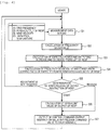
Fig. 4] Fig. 4 is a control flowchart of the control device in Example 1 of the control system of the renewable energy power generation equipment of the invention. - [
Fig. 5] Fig. 5 is a diagram describing a determination method of output restriction in Example 1 of the control system of the renewable energy power generation equipment of the invention. - [
Fig. 6] Fig. 6 is a diagram describing a control operation example in Example 1 of the control system of the renewable energy power generation equipment of the invention. - [
Fig. 7] Fig. 7 is a diagram describing another control operation example in Example 1 of the control system of the renewable energy power generation equipment of the invention. - [
Fig. 8] Fig. 8 is a schematic configuration diagram illustrating a renewable energy power generation system that is Example 2 of the invention. - [
Fig. 9] Fig. 9 is a diagram illustrating a detailed configuration of a control system in the renewable energy power generation system that is Example 2 of the invention. - [
Fig. 10] Fig. 10 is a control flowchart of the control system in the renewable energy power generation system that is Example 2 of the invention. - [
Fig. 11] Fig. 11 is a diagram describing a control operation example in the renewable energy power generation system that is Example 2 of the invention. - Hereinafter, a control system of renewable energy power generation equipment, a control method thereof, and a renewable energy power generation system of the invention will be described with reference to illustrated examples. Moreover, for reference numerals, the same reference numerals are used for the same configuration components in each view.
-
Fig. 2 is an example of a schematic configuration of renewable energy power generation equipment (hereinafter, referred to as RES power generation equipment) according to an embodiment of the invention. The RES power generation equipment configured of windpower generation equipment power generation equipment 51 of which power outputs are changed in response to meteorological conditions are connected to apower grid 1 which is formed by connecting large-scale generation equipment G1 and G2 of power grids corresponding to a thermal power station, a hydroelectric power station, and the like, and thesubstations power transmission line 3. The power output of each piece of RES power generation equipment is supplied to each customer (not illustrated) connected to the power grid through thepower transmission line 3. - The RES power generation equipment does not need to be installed so as to be concentrated within a particular area and are respectively installed by being distributed at locations at which good wind situation and insolation conditions are provided. In
Fig. 2 , only the windpower generation equipment power generation equipment 51 are illustrated as the RES power generation equipment for simplicity, but in fact, it is assumed that more RES power generation equipment is connected to thepower grid 1. In addition, as elements configuring the RES power generation equipment and thepower grid 1, the minimum number of elements necessary for describing the invention are described. - The wind
power generation equipment generation system groups connection transformers generation system groups power grid 1, andcontrol devices power generation equipment generation system groups voltage detectors current detectors power grid 1, and meteorological characteristics (wind velocity, wind direction, air temperature, and the like) that are measured by an anemometer and the like installed in the windmill. - Similarly, the solar
power generation equipment 51 is configured of a solar power generation system formed of a plurality ofsolar panels 51a, aconnection power converter 51e, and the like, aconnection transformer 51b for connecting the plurality ofsolar panels 51a to thepower grid 1, and acontrol device 50 that has functions of calculating and transmitting control commands for adjusting an output of the solarpower generation equipment 51, based on a power output of the solar power generation system, a voltage and a current that are measured by avoltage detector 51c and acurrent detector 51d measuring a voltage and a current of a connection point of thepower grid 1, and meteorological characteristics (insolation amount, air temperature, and the like) that are measured by an insolation amount meter and a thermometer installed in thesolar panel 51a. -
Fig. 3 illustrates a functional configuration diagram of thecontrol device 40a of the windpower generation equipment 41. Functional configurations of thecontrol devices power generation equipment control device 50 of the solarpower generation equipment 51 are also similar and here, the windpower generation equipment 41 is mainly described. - As illustrated in the view, the
control device 40a of the windpower generation equipment 41 is schematically configured of acontrol calculation device 401 that calculates the control commands transmitted to the wind powergeneration system group 41a, adata storage device 405 that stores the measurement information, a history of the control commands, and the like of the windpower generation equipment 41, aninput device 402 into which an operator inputs operation commands, adisplay device 403 in which the operator checks operation situations and the like, and acommunication device 404 for controlling transmitting and receiving of the control commands and the measurement information. Thecommunication device 404 performs information communication with the wind powergeneration system group 41a through the communication line. - Furthermore, the
control calculation device 401 is configured of a measurementdata processing section 401a, a frequencydeviation calculation section 401b for calculating a frequency deviation Δf from a frequency f of thepower grid 1 detected from a voltage waveform measured by thevoltage detector 41c, an expected power output-increase and decreasecalculation section 401c that calculates an expected power output P1* and an increase and decrease state value of the windpower generation equipment 41 from a measured wind velocity, a correlationcoefficient calculation section 401d that calculates a correlation coefficient C1 between the frequency deviation Δf and the expected power output P1*, an outputadjustment determination section 401e that performs determination whether or not the output adjustment of the windpower generation equipment 41 is performed by the correlation coefficient and the increase and decrease state value of the expected power output, and an output adjustmentcommand calculation section 401f that calculates an output adjustment command value. - Next, flows of processing of the
control devices power generation equipment Fig. 4 . - As illustrated in
Fig. 4 , first, in step S1, electrical characteristic data such as the frequency of thepower grid 1, the voltage, and the current of the connection point, and the meteorological characteristic data such as the wind velocity that is periodically measured and transmitted by the windpower generation equipment data storage device 405. In a case of the solarpower generation equipment 51, the insolation amount and the air temperature are read instead of the wind velocity. - In step S2, the frequency deviation Δf as a difference with a rated frequency fo is calculated in Expression (1) by using the measured frequency f of the
power grid 1.
- Here, f: measurement value of frequency (Hz)
- fo: rated frequency of power grid (Hz)
- In step S3, expected power outputs P1*, P2*, and P3* in each piece of of the wind
power generation equipment power generation equipment 
- Here, Pi*: expected power output of ith wind power generation equipment (MW)
- p: air density (kg/m3)
- Ai: wind receiving area of windmill blades of ith wind power generation equipment (m2)
- Vi: wind velocity measured in ith wind power generation equipment (m/s)
- Hi: power efficiency of wind power generation system of ith wind power generation equipment (%)
- Furthermore, the increase and decrease state value ΔPi* of the expected power output is calculated by Expression (3) by using the expected power output P1* and a moving average deviation Pi*_ave obtained by Expression (2).

- Here, φ(x) is a symbol function that is defined in Expression (4).

- Here, ε+: upper limit value of dead zone of change amount of expected power output
- ε-: lower limit value of dead zone of change amount of expected power output
- The expected power output Pi* of the solar
power generation equipment 51 is calculated by Expression (5) by using an insolation amount measurement value Sr (W/m2) and an outside temperature To (°C).
- Here, Ks: insolation amount correction coefficient
- Kpv: panel capacity conversion coefficient
- Kt (To): temperature correction coefficient
- Kb: dirt coefficient
- Kc: cable efficiency coefficient
- Kpcs: PCS conversion efficiency coefficient
- In step S4, in order to evaluate influences of outputs of the wind
power generation equipment power grid 1, a correlation coefficient Ci between the frequency deviation Δf of thepower grid 1 and the expected power output Pi* of the windpower generation equipment 
- Here, Δf and Pi* use data for past n point going back from the current time.
- In step S5, it is determined whether or not the output restriction is performed or whether or not the output restriction is released in the wind
power generation equipment 


- A determination method of the output restriction described above will be described with reference to
Fig. 5. Fig. 5(a) illustrates a case where a positive correlation exists in the frequency deviation Δf and a deviation ΔPi* of the expected power output,Fig. 5(b) illustrates a case where non-correlation exists in both, andFig. 5(c) illustrates a case where a negative correlation exists in both. - If the positive correlation of
Fig. 5(a) exists, since all of Expressions (7), (8), and (9) are satisfied, the output restriction is started at the time of Expression (9) being satisfied. As illustrated inFig. 5(b) , if there is non-correlation in the frequency deviation Δf and the deviation ΔPi* of the expected power output, although Expression (7) is satisfied, Pi* is hardly changed with respect to a change in the frequency and ΔPi* is substantially zero. Thus, Expression (8) and Expression (9) are not satisfied, and the output restriction is not performed. Furthermore, as illustrated inFig. 5(c) , if the negative correlation exists in the frequency deviation ΔPi and the deviation ΔPi* of the expected power output, although Expression (7) is satisfied, Pi* is reduced in contrary and ΔPi* is a negative value. Thus, Expression (8) and Expression (9) are not satisfied, and the output restriction is not performed. - Furthermore, release of the output restriction is not illustrated, but as indicated in Expression (10), the output restriction is released if the frequency deviation Δf is lower than a negative threshold value ηΔfn.

- In step S6, a target value Pi_tg of the output restriction performed in the wind
power generation equipment power generation equipment 
- Here, ξ: ratio (0<ξ<1)
- m: number of wind power generation systems in wind
power generation equipment 41 - Finally, in step S7, the target value is transmitted to each windmill of each of the wind power
generation system groups -
Fig. 6 illustrates a control operation example of the control system of the renewable energy power generation equipment in Example 1 of the invention. Here, for ease of understanding, a case where two windpower generation equipment power grid 1 is assumed and described. -
Fig. 6 is an example of a case where the expected power output P1* obtained from the wind velocity in the windpower generation equipment 41 is monotonically increased from a constant and an expected power output P2* is substantially constant in the windpower generation equipment 42. In the windpower generation equipment 41, a control operation of a case where the frequency of thepower grid 1 is increased with an increase in the expected power output P1* is described. - At time (a) indicated in
Fig. 6 , it is detected that the frequency deviation Δf exceeds the positive threshold value ηΔfp. In this case, the correlation coefficient C1 is started to be increased from zero, but as described in Expression (6), since calculation is performed by using the data for past n point going back from the current time, the frequency deviation Δf has characteristics slightly delayed from the changes in Δf and P1*, and is lower than the threshold value ηc at the time. - Next, at time (b), it is detected that the correlation coefficient C1 exceeds the positive threshold value ηc. In this case, since the expected power output P1* tends to be increased and the deviation Δ P1* of Expression (3) is positive, the wind power generation system configuring the wind
power generation equipment 41 starts the output restriction aiming to the target value. The frequency of thepower grid 1 is started to be reduced from time (c) by the influence. In the wind power generation system, the output is further reduced aiming to the target value. - At time (d), since it is detected that the frequency deviation Δf of the
power grid 1 is lower than the negative threshold value ηΔfn, a release command of the output restriction is transmitted to the wind power generation system and, as a result, the output P1 of the windpower generation equipment 41 is increased according to the wind velocity. In this case, in the windpower generation equipment 42 in which the output is substantially constant, since Expressions (8) and (9) are not satisfied, the output restriction is not applied. - As described above, according to the example, when the frequency of the power grid is increased, the output restriction is not performed in all wind power generation equipment and the output restriction can be performed only in the wind power generation equipment which affects the increase in the frequency. Thus, it is possible to contribute to suppression of the frequency variation of the LFC region by effective output adjustment of the minimum required.
- Another control operation example of the control system of the renewable energy power generation equipment in Example 1 of the invention will be described with reference to
Fig. 7 . Similar toFig. 6 , a case where two windpower generation equipment Fig. 7 is an example of a case where the expected power output P1* obtained from the wind velocity in the windpower generation equipment 41 is monotonically increased from a constant, the expected power output P2* is substantially monotonically decreased from the constant and then is started to be increased in the windpower generation equipment 42. - First, a case where the frequency of the
power grid 1 is increased together with the increase in the expected power output P1* of the windpower generation equipment 41 is assumed and a control operation at this time is described. - At time (a) indicated in
Fig. 7 , it is detected that the frequency deviation Δf exceeds the positive threshold value ηΔfp. The correlation coefficient C1 is started to be increased from zero, but as described in Expression (6), since calculation is performed by using the data for past n point going back from the current time, the frequency deviation Δf has characteristics slightly delayed from the changes in Δf and P1*, and is lower than the threshold value at the time. - Next, at time (b), it is detected that the correlation coefficient C1 exceeds the positive threshold value ηc. In this case, since the expected power output P1* tends to be increased and the deviation Δ P1* of Expression (3) is positive, the wind power generation system configuring the wind
power generation equipment 41 starts the output restriction aiming to the target value. The frequency of thepower grid 1 is started to be reduced from time (c) by the influence. In the wind power generation system, the output is further reduced aiming to the target value. On the other hand, in the windpower generation equipment 42, Expressions (8) and (9) are not satisfied, the output restriction is not applied. - Next, at time (d), since the output of the wind
power generation equipment 42 is started to be increased, the frequency is started to be increased. At time (e), in the windpower generation equipment 42, since a correlation coefficient C2 exceeds positive threshold value ηc and the expected power output tends to be increased, the output restriction is started. As a result, the increased frequency tends to be reduced again and at time (d), it is detected that the frequency deviation Δf of thepower grid 1 is lower than the negative threshold value ηΔfn. Thus, the release command of the output restriction is transmitted to the wind power generation system of the windpower generation equipment power generation equipment - As described above, according to the example, the output is adjusted while the wind power generation station performs the output restriction or releases the output restriction from time to time depending on a degree of influence for the expected power generation amount by the wind velocity on the increase in the frequency of the power grid. Thus, similar to
Fig. 6 , it is possible to contribute to suppression of the frequency variation of the LFC region by effective output adjustment of the minimum required. - According to the example described above, excessive output restriction of the renewable energy power generation equipment is prevented and suppressed without using auxiliary equipment such as battery with respect to the frequency variation of the LFC region of several minutes or more, which is the most effective in the frequency maintenance of the power grid and to which the output adjustment of a period of approximately several seconds of the single wind power generation system that is the related art cannot correspond.
- Next, a renewable energy power generation system including a plurality of RES power generation groups, which is Example 2 of the invention, will be described with reference to
Figs. 8 and 9 . -
Fig. 8 is an example of a schematic configuration of the renewable energy power generation system including the RES power generation groups. - As illustrated in
Fig. 8 , the RES power generation equipment formed of windpower generation equipment power generation equipment 51 of which power outputs are changed in response to meteorological conditions are connected to apower grid 1 which is formed by connecting large-scale generation equipment G1 and G2 corresponding to a thermal power station, a hydroelectric power station, and the like, andsubstations power transmission line 3. The power output of each piece of RES power generation equipment is supplied to each customer (not illustrated) connected to thepower grid 1 through apower transmission line 3. The RES power generation equipment are not need to be installed to be concentrated within a particular area and are respectively installed by being distributed at locations at which good wind situations and insolation conditions are provided. - In
Fig. 8 , as the RES power generation equipment, only the windpower generation equipment power generation equipment 51 are illustrated, but in fact, it is assumed that more plurality of power generation equipment are connected. In addition, as elements configuring the renewable energy power generation system and thepower grid 1, the minimum number of elements necessary for describing the invention are described. - The wind
power generation equipment generation system groups connection transformers generation system groups power grid 1, andcontrol devices power generation equipment generation system groups voltage detectors current detectors power grid 1, and meteorological characteristics (wind velocity, wind direction, air temperature, and the like). - Similarly, the solar
power generation equipment 51 is configured of a solar power generation system formed of a plurality ofsolar panels 51a, aconnection transformer 51b for connecting the plurality ofsolar panels 51a to thepower grid 1, avoltage detector 51c and acurrent detector 51d that measure total power generation outputs of the plurality ofsolar panels 51a, and the voltages and the currents of the connection points to thepower grid 1, aconnection power converter 51e, and the like, and acontrol device 50 that has functions of calculating and transmitting control commands for adjusting an output of the solarpower generation equipment 51, based on a power output of the solar power generation system, electrical characteristics such as the voltage of the grid connection point, and meteorological characteristics (insolation amount, air temperature, and the like). - Moreover, the
control devices - The wind
power generation equipment power generation equipment 51 configuring the RES power generation equipment groups are connected to acontrol system 6 of the RES power generation equipment groups through acommunication line 7. Input and output of information between each piece of of thepower generation equipment control system 6 are performed through thecommunication line 7. -
Fig. 9 illustrates a functional configuration diagram of thecontrol system 6 of the RES power generation equipment groups. As illustrated in the view, thecontrol system 6 of the RES power generation equipment groups of the example is configured of acontrol calculation device 61 that calculates the control commands transmitted to thecontrol devices data storage device 65 that stores the measurement information, a history of the control commands, and the like of the RES power generation equipment groups, aninput device 62 into which an operator inputs operation commands, adisplay device 63 in which the operator checks operation situations and the like, and acommunication device 64 for controlling transmitting and receiving of the control commands and the measurement information. Thecommunication device 64 performs information communication with the RES power generation equipment groups through thecommunication line 7. - Furthermore, the
control calculation device 61 is configured of a measurementdata processing section 61a, a frequencydeviation calculation section 61b for outputting a frequency deviation Δf from a frequency f of thepower grid 1, an expected power output-increase and decreasecalculation section 61c that calculates an expected power output P1* and an increase and decrease state of the windpower generation equipment 41 from a measured wind velocity, a correlationcoefficient calculation section 61d that outputs a correlation coefficient C1 between the frequency deviation Δf and the expected power output P1*, an outputadjustment determination section 61e that performs determination whether or not the output adjustment of the windpower generation equipment 41 is performed by the correlation coefficient and the increase and decrease state of the expected power output, an output adjustmentcommand calculation section 61f that outputs an output adjustment command value, an accumulated output restrictionamount calculation section 61g that outputs the accumulative value of the power amount in which the output restriction of each piece of RES power generation equipment is performed. - Next, flows of processing in the
control system 6 of the RES power generation equipment groups will be described with reference toFig. 10 . - As illustrated in
Fig. 10 , first, in step S1, electrical characteristic data such as the frequency of thepower grid 1, the voltage, and the current of the connection point, and the meteorological characteristic data such as the wind velocity from the windpower generation equipment power generation equipment 51 which are periodically measured by each piece of the RES power generation equipment are read from thedata storage device 65. - In step S2, the frequency deviation Δf as a difference with a rated frequency fo is calculated in Expression (1) described above by using the measured frequency f of the
power grid 1. - In step S3, an expected power output Pi* of each piece of RES power generation equipment is calculated. In each piece of of the wind
power generation equipment power generation equipment power generation equipment 51, calculation is performed by Expression (5) described above by using the insolation amount measurement value Sr (W/m2) and the outside temperature To (°C). Furthermore, the deviation ΔPi* indicating the increase and decrease state of the expected power output is calculated by Expression (3) described above by using the expected power output Pi* obtained in Expression (2) and a moving average deviation Pi*_ave. - In step S4, in order to evaluate influences of outputs of the wind
power generation equipment power grid 1, a correlation coefficient Ci between the frequency deviation Δf of the power generation equipment is calculated by Expression (6) described above. - In step S5, an accumulative value Pi_loss of the power amount that can not be output by performing the output restriction in each piece of RES power generation equipment is calculated by Expression (12). That is, it represents that the RES power generation equipment having large value of Pi_loss contributes to suppression of the frequency variation.

- In step S6, it is determined whether or not the output restriction is performed or whether or not the output restriction is released in each piece of RES power generation equipment. First, similar to
Fig. 4 , the output restriction is performed only in a case where three conditions indicated in Expressions (7), (8), and (9) described above are satisfied. - In step S7, a target value Pi_tg of the output restriction that is performed in the RES power generation equipment is calculated. For example, as indicated in Expression (11) described above, an current output Pi of the wind power generation equipment is restricted at a predetermined ratio. Otherwise, a predetermined minimum output value Pi_min may be the target value of the output restriction. In this case, if the current output Pi of the wind power generation equipment is restricted at a predetermined ratio by Expression (11), the ratio ξ (0<ξ<1) of Expression (11) is increased such that the output restriction amount is increased as the RES power generation equipment has a small accumulative value Pi_loss of the power amount of the output restriction of each piece of RES power generation equipment calculated in Expression (12). Similarly, if a predetermined minimum output value Pi_min is the target value of the output restriction, the value of Pi_loss is decreased such that the output restriction amount is increased as the RES power generation equipment has a small accumulative value Pi_loss of the power amount of the output restriction.
- Finally, in step S8, the target value is transmitted to each piece of RES power generation equipment. In this case, an upper limit value of an output change rate that is defined by an output change amount per unit time is also transmitted. This is, for example, 10%/20 minutes of the rated output as the output change rate in a process necessary for satisfying connection conditions of the wind power generation equipment.
- A control operation example of the
control system 6 of the RES power generation equipment groups in Example 2 of the invention will be described with reference toFig. 11 . Here, for ease of understanding, a case where two windpower generation equipment power grid 1 is assumed and described. -
Fig. 11 (a) is an example of a case where a total expected power outputs ΣPi* of the RES power generation equipment groups are monotonically increased from a constant when the frequency of thepower grid 1 is increased. - First, at time (a), it is detected that the frequency deviation Δf exceeds the positive threshold value ηΔfp. The correlation coefficient Ci between the frequency deviation and the total expected power outputs ΣPi* of the RES power generation station groups is started to be increased from zero, but as described in Expression (6), since calculation is performed by using the data for past n point going back from the current time, the frequency deviation Δf has characteristics slightly delayed from the changes in Δf and ΣPi*, and is lower than the threshold value ηc at the time.
- Next, at time (b), it is detected that the correlation coefficient Ci exceeds the positive threshold value ηc. In this case, since the total expected power output ΣPi* tends to be increased and the deviation ΔPi* of Expression (3) is positive, the wind
power generation equipment 41 and the windpower generation equipment 42, in which the outputs tend to be increased, start the output restriction aiming to the target value. The frequency of the power grid is started to be reduced from time (c) by the influence. In the wind power generation system, the output is further reduced aiming to the target value. - At time (d), since it is detected that the frequency deviation Δf of the
power grid 1 is lower than the negative threshold value ηΔfn, a release command of the output restriction is transmitted to the windpower generation system 41 and the windpower generation equipment 42 configuring the RES power generation equipment groups and, as a result, the outputs P1 and P2 of the windpower generation equipment -
Fig. 11 (b) is an example of a case where aspects of output changes are different in the windpower generation equipment 41 and the windpower generation equipment 42 configuring the RES power generation equipment groups. Specifically, the windpower generation equipment 41 is monotonically increased and the windpower generation equipment 42 is monotonically decreased. In this case, both output changes are offset and then the total expected power outputs ΣPi* of the RES power generation equipment groups are substantially constant. In this case, since the frequency of thepower grid 1 and the total expected power outputs are uncorrelated, the output restriction does not occur. As the RES power generation equipment groups, this can be said as appropriate control because it does not affect the frequency increase of thepower grid 1. - According to the example described above, of course, the same effects as those of Example 1 are obtained and it is possible to suppress the total output restriction amounts and to contribute to maintenance of the frequency compared to a case where it is determined whether or not the output restriction is necessary in each piece of RES power generation equipment described in
Figs. 6 and7 . - Moreover, the invention is not limited to the examples described above and includes various modifications. For example, the examples described above are those described in detail in order to clearly and easily describe the invention and are not intended to be limited to all necessary configurations described. Furthermore, it is possible to replace a part of the configuration of an example in the configuration of another example and it is possible to add the configuration of another example to the configuration of an example. Furthermore, it is possible to make addition, deletion, and substitution of other configurations to a part of the configuration of each example.
- 1 ··· power grid, 3 ··· power transmission line, 6 ··· control system of renewable energy power generation equipment group, 7 ··· communication line, 21, 22, 23, 24, 25 ··· substation, 40a, 40b, 40c ··· control device of wind power generation equipment, 41, 42, 43 ··· wind power generation equipment, 41a, 42a, 43a ... wind power generation system group, 41b, 42b, 43b ··· connection transformer, 41c, 42c, 43c ··· voltage detector, 41d, 42d, 43d ··· current detector, 50 ... control device of solar power generation equipment, 51 ··· solar power generation equipment, 51a ··· solar panel, 51b ··· connection transformer, 51c ··· voltage detector, 51d ··· current detector, 51e ··· connection power converter, 61, 401 ··· control calculation device, 61a, 401a ··· measurement data processing section, 61b, 401b ... frequency deviation calculation section, 61c, 401c ... expected power output-increase and decrease calculation section, 61d, 401d ··· correlation coefficient calculation section, 61e, 401e ··· output adjustment determination section, 61f, 401f ··· output adjustment command calculation section, 61g ··· accumulated output restriction amount calculation section, 62, 402 ··· input device, 63, 403 ··· display device, 64, 404 ··· communication device, 65, 405 ··· data storage device.
Claims (14)
- A control system of renewable energy power generation equipment, which controls renewable energy power generation equipment which includes a plurality of power generation devices generating power by using renewable energy sources and in which the plurality of power generation devices are operated by being connected to a power grid, the control system comprising:a measuring unit that measures a frequency of the power grid;a measuring unit that measures meteorological characteristics of the renewable energy power generation equipment;a calculating unit that calculates frequency deviation of the power grid;a calculating unit that calculates an expected power output of the renewable energy power generation equipment and an increase and decrease state value thereof based on the meteorological characteristics measured by the measuring unit that measures meteorological characteristics of the renewable energy power generation equipment;a calculating unit that calculates a correlation coefficient between the frequency deviation of the power grid and the expected power output of the renewable energy power generation equipment; anda determining unit that determines whether or not output adjustment of the renewable energy power generation equipment is necessary by using the correlation coefficient between the frequency deviation and the expected power output, and the increase and decrease state value of the expected power output.
- The control system of renewable energy power generation equipment according to claim 1,
wherein in the determining unit that determines whether or not the output adjustment of the renewable energy power generation equipment is necessary, when the frequency deviation exceeds a predetermined positive threshold value, the correlation coefficient exceeds a positive threshold value, and the expected power output is in an increasing state, an output of a renewable energy power generation station is restricted and when the frequency deviation is lower than a predetermined negative threshold value, output restriction of the renewable energy power generation equipment is released. - The control system of renewable energy power generation equipment according to claim 1 or 2,
wherein the plurality of power generation devices generating power by using the renewable energy sources are wind power generation equipment, and
wherein the wind power generation equipment includes a wind power generation system that is formed of at least a plurality of windmills, generators, and a connection power converter, a connection transformer for connecting the wind power generation system to the power grid, a voltage detector and a current detector that measure a voltage and a current of a connection point to the power grid, and a control device that has a function of calculating and transmitting control commands for adjusting an output of the wind power generation equipment based on the voltage and the current that are measured by the voltage detector and the current detector, a power generation output of the wind power generation system, and at least a wind velocity. - The control system of renewable energy power generation equipment according to claim 1 or 2,
wherein the plurality of power generation devices generating power by using the renewable energy sources are solar power generation equipment, and
wherein the solar power generation equipment includes a plurality of solar panels, a connection transformer for connecting the solar panels to the power grid, a voltage detector and a current detector that measure a voltage and a current of a connection point to the power grid, a control device that has a function of calculating and transmitting control commands for adjusting an output of the solar power generation equipment based on the voltage and the current that are measured by the voltage detector and the current detector, a power generation output of the solar panels, an insolation amount, and an air temperature. - The control system of renewable energy power generation equipment according to claim 3 or 4,
wherein the control device is configured of a control calculation device that calculates the control commands to be transmitted to the wind power generation equipment or the solar power generation equipment, a data storage device that stores measurement information and/or a history of the control commands of the wind power generation equipment or the solar power generation equipment, an input device to which an operator inputs operation commands, a display device in which the operator checks operation situations, and a communication device for controlling transmitting and receiving of the measurement information and/or the control commands of the wind power generation equipment or the solar power generation equipment. - The control system of renewable energy power generation equipment according to claim 5,
wherein the control calculation device is configured of a measurement data processing section that processes data from the data storage device, a frequency deviation calculation section for calculating the frequency deviation from a frequency of the power grid which is processed by the measurement data processing section, an expected power output-increase and decrease calculation section that calculates the expected power output of the wind power generation equipment or the solar power generation equipment and the increase and decrease state value thereof from the wind velocity, or the insolation amount, and the air temperature processed in the measurement data processing section, a correlation coefficient calculation section that calculates the correlation coefficient between the frequency deviation calculated by the frequency deviation calculation section and the expected power output calculated by the expected power output-increase and decrease calculation section, an output adjustment determination section that performs determination on whether or not the output adjustment of the wind power generation equipment or the solar power generation equipment is performed by using the correlation coefficient calculated by the correlation coefficient calculation section and the increase and decrease state value calculated by the expected power output-increase and decrease calculation section, and an output adjustment command calculation section that calculates an output adjustment command value of the output adjustment determination section. - A control method of renewable energy power generation equipment, which controls renewable energy power generation equipment which includes a plurality of power generation devices generating power by using renewable energy sources and in which the plurality of power generation devices are operated by being connected to a power grid, the control method comprising:calculating an expected power output of the renewable energy power generation equipment and an increase and decrease state value thereof by using a calculating unit that calculates the expected power output of the renewable energy power generation equipment and the increase and decrease state value thereof based on meteorological characteristics measured by a measuring unit that measures the meteorological characteristics of the renewable energy power generation equipment;calculating a correlation coefficient of the expected power output of the renewable energy power generation equipment by using a calculating unit that calculates the correlation coefficient between the frequency deviation of the power grid calculated by the calculating unit that calculates the frequency deviation of the power grid and the expected power output of the renewable energy power generation equipment; anddetermining whether or not output adjustment of the renewable energy power generation equipment is necessary by using the calculated correlation coefficient between the frequency deviation and the expected power output, and an increase and decrease state value of the expected power output.
- The control method of renewable energy power generation equipment according to claim 7,
wherein in the determining on whether or not the output adjustment of the renewable energy power generation equipment is necessary, when the frequency deviation exceeds a predetermined positive threshold value, the correlation coefficient exceeds a positive threshold value, and the expected power output is in an increasing state, an output of a renewable energy power generation station is restricted and when the frequency deviation is lower than a predetermined negative threshold value, output restriction of the renewable energy power generation equipment is released. - A renewable energy power generation system that is configured of a plurality of renewable energy power generation equipment connected to a power grid, the renewable energy power generation equipment including the control system of renewable energy power generation equipment according to any one of claims 1 to 6.
- The renewable energy power generation system according to claim 9,
wherein the plurality of renewable energy power generation equipment are connected to the control system through a communication line,
wherein the control system includes a measuring unit that measures a frequency of the power grid, a measuring unit that measures meteorological characteristics of each piece of the renewable energy power generation equipment, a calculating unit that calculates frequency deviation of the power grid, a calculating unit that calculates an expected power output of each piece of the renewable energy power generation equipment and an increase and decrease state value thereof based on the meteorological characteristics measured by the measuring unit that measures meteorological characteristics of the renewable energy power generation equipment, a calculating unit that calculates a correlation coefficient between the frequency deviation of the power grid and the expected power output of each piece of the renewable energy power generation equipment, and a determining unit that determines whether or not output adjustment of each piece of the renewable energy power generation equipment is necessary by using the correlation coefficient between the frequency deviation and the expected power output, and the increase and decrease state value of the expected power output. - The renewable energy power generation system according to claim 10,
wherein in the determining unit that determines whether or not the output adjustment of each piece of the renewable energy power generation equipment is necessary, when the frequency deviation exceeds a predetermined positive threshold value, the correlation coefficient exceeds a positive threshold value, and the expected power output is in an increasing state, an output of a renewable energy power generation station is restricted and when the frequency deviation is lower than a predetermined negative threshold value, output restriction of the renewable energy power generation equipment is released. - The renewable energy power generation system according to claim 10 or 11,
wherein priorities of the renewable energy power generation equipment performing the output restriction are determined by using an integrated value of an output restriction amount of each piece of the renewable energy power generation equipment. - The renewable energy power generation system according to claim 9,
wherein the plurality of renewable energy power generation equipment are connected to the control system through the communication line, and
wherein the control system is configured of a control calculation device that calculates control commands to be transmitted to each piece of the renewable energy power generation equipment, a data storage device that stores measurement information and/or a history of the control commands of each piece of the renewable energy power generation equipment, an input device to which an operator inputs operation commands, a display device in which the operator checks operation situations, and a communication device for controlling transmitting and receiving of the measurement information and/or the control commands of each piece of the renewable energy power generation equipment. - The renewable energy power generation system according to claim 13,
wherein the control calculation device is configured of a measurement data processing section that processes data from the data storage device, a frequency deviation calculation section for calculating the frequency deviation from a frequency of the power grid which is processed by the measurement data processing section, an expected power output-increase and decrease calculation section that calculates the expected power output of each piece of the renewable energy power generation equipment and the increase and decrease state value thereof from meteorological characteristics of each piece of the renewable energy power generation equipment processed in the measurement data processing section, a correlation coefficient calculation section that calculates the correlation coefficient between the frequency deviation calculated by the frequency deviation calculation section and the expected power output calculated by the expected power output-increase and decrease calculation section, an output adjustment determination section that performs determination on whether or not the output adjustment of each piece of the renewable energy power generation equipment is performed by using the correlation coefficient calculated by the correlation coefficient calculation section and the increase and decrease state value calculated by the expected power output increase and decrease calculation section, an output adjustment command calculation section that calculates an output adjustment command value of the output adjustment determination section, and an accumulative output restriction amount calculation section that calculates an accumulative value of a power amount of each piece of the renewable energy power generation equipment that is output-restricted.
Applications Claiming Priority (1)
| Application Number | Priority Date | Filing Date | Title |
|---|---|---|---|
| PCT/JP2013/067041 WO2014203388A1 (en) | 2013-06-21 | 2013-06-21 | Control system for renewable energy power generation facilities, method for controlling same, and renewable energy power generation system |
Publications (3)
| Publication Number | Publication Date |
|---|---|
| EP3012937A1 true EP3012937A1 (en) | 2016-04-27 |
| EP3012937A4 EP3012937A4 (en) | 2017-02-15 |
| EP3012937B1 EP3012937B1 (en) | 2020-03-25 |
Family
ID=52104150
Family Applications (1)
| Application Number | Title | Priority Date | Filing Date |
|---|---|---|---|
| EP13887235.3A Active EP3012937B1 (en) | 2013-06-21 | 2013-06-21 | Control system for renewable energy power generation facilities, method for controlling same, and renewable energy power generation system |
Country Status (4)
| Country | Link |
|---|---|
| EP (1) | EP3012937B1 (en) |
| JP (1) | JP6082811B2 (en) |
| ES (1) | ES2781575T3 (en) |
| WO (1) | WO2014203388A1 (en) |
Cited By (3)
| Publication number | Priority date | Publication date | Assignee | Title |
|---|---|---|---|---|
| CN106451499A (en) * | 2016-12-12 | 2017-02-22 | 哈尔滨工业大学 | Dynamic primary thermal power generating unit frequency modulation control method for power grid with high wind power penetration rate |
| CN111130095A (en) * | 2018-10-30 | 2020-05-08 | Abb瑞士股份有限公司 | Method for predicting power production of renewable energy power plant |
| CN112821419A (en) * | 2021-01-21 | 2021-05-18 | 中国三峡新能源(集团)股份有限公司 | Power grid frequency modulation limit analysis method and system |
Families Citing this family (4)
| Publication number | Priority date | Publication date | Assignee | Title |
|---|---|---|---|---|
| CN108377005B (en) * | 2018-04-04 | 2021-02-23 | 国电南瑞科技股份有限公司 | ACE interval-based active real-time cooperative control method for multiple types of power supplies |
| CN111668858B (en) * | 2020-06-15 | 2021-07-27 | 中国电力科学研究院有限公司 | Demand side resource optimal coordination control method and system considering intermittent characteristics |
| CN113408892B (en) * | 2021-06-18 | 2023-03-24 | 浙江中新电力工程建设有限公司 | Layered cooperative regulation and control system for guaranteeing multi-energy complementary microgrid and regulation and control method thereof |
| CN115833184B (en) * | 2023-02-22 | 2023-05-09 | 浙江大学 | Wind farm primary frequency modulation method based on accurate control of power of energy management system |
Family Cites Families (5)
| Publication number | Priority date | Publication date | Assignee | Title |
|---|---|---|---|---|
| JP2007009804A (en) * | 2005-06-30 | 2007-01-18 | Tohoku Electric Power Co Inc | Schedule system for output-power control of wind power-plant |
| ES2327486B1 (en) * | 2008-03-14 | 2010-07-14 | Ingeteam Energy, S.A. | METHOD OF OPERATION OF A WIND TURBINE TO GUARANTEE PRIMARY OR SECONDARY REGULATION IN AN ELECTRICAL NETWORK. |
| US8301311B2 (en) * | 2009-07-06 | 2012-10-30 | Siemens Aktiengesellschaft | Frequency-responsive wind turbine output control |
| WO2012019613A1 (en) * | 2010-08-13 | 2012-02-16 | Vestas Wind Systems A/S | Wind-power production with reduced power fluctuations |
| JP5576826B2 (en) * | 2011-05-18 | 2014-08-20 | 株式会社日立製作所 | Wind power generator group control system and control method |
-
2013
- 2013-06-21 JP JP2015522450A patent/JP6082811B2/en not_active Expired - Fee Related
- 2013-06-21 EP EP13887235.3A patent/EP3012937B1/en active Active
- 2013-06-21 ES ES13887235T patent/ES2781575T3/en active Active
- 2013-06-21 WO PCT/JP2013/067041 patent/WO2014203388A1/en active Application Filing
Non-Patent Citations (1)
| Title |
|---|
| See references of WO2014203388A1 * |
Cited By (3)
| Publication number | Priority date | Publication date | Assignee | Title |
|---|---|---|---|---|
| CN106451499A (en) * | 2016-12-12 | 2017-02-22 | 哈尔滨工业大学 | Dynamic primary thermal power generating unit frequency modulation control method for power grid with high wind power penetration rate |
| CN111130095A (en) * | 2018-10-30 | 2020-05-08 | Abb瑞士股份有限公司 | Method for predicting power production of renewable energy power plant |
| CN112821419A (en) * | 2021-01-21 | 2021-05-18 | 中国三峡新能源(集团)股份有限公司 | Power grid frequency modulation limit analysis method and system |
Also Published As
| Publication number | Publication date |
|---|---|
| JP6082811B2 (en) | 2017-02-15 |
| WO2014203388A1 (en) | 2014-12-24 |
| ES2781575T3 (en) | 2020-09-03 |
| JPWO2014203388A1 (en) | 2017-02-23 |
| EP3012937A4 (en) | 2017-02-15 |
| EP3012937B1 (en) | 2020-03-25 |
Similar Documents
| Publication | Publication Date | Title |
|---|---|---|
| EP3012937B1 (en) | Control system for renewable energy power generation facilities, method for controlling same, and renewable energy power generation system | |
| JP5647329B2 (en) | New energy power plant group control system and control method thereof | |
| KR101398400B1 (en) | Time-variant droop based inertial control method for wind power plant | |
| US8332077B2 (en) | Controller and control method for a wind farm including a plurality of wind turbine generators | |
| JP6081133B2 (en) | Wind farm output control device, method, and program | |
| US8942856B2 (en) | Power converter and methods of controlling the same | |
| JP6163558B2 (en) | Solar power system | |
| EP2328259A1 (en) | System and method for power management in a photovoltaic installation | |
| US20150214741A1 (en) | System control device and system control method | |
| JP5957372B2 (en) | Solar radiation amount calculation method and supply power determination method | |
| JP2010041802A (en) | Controller of secondary battery and control method | |
| JP2010130762A (en) | Electric power supply system containing natural energy generating apparatus and supply/demand adjusting method | |
| US10468888B2 (en) | Control system for solar power plant | |
| JP2020022241A (en) | Hybrid power generation system and power control device | |
| JP6375161B2 (en) | Renewable energy power plant control system | |
| JP2006042458A (en) | Frequency controller and system frequency controlling method | |
| KR20190036914A (en) | High Efficiency Photovoltaic System Using DC-DC Voltage Regulator | |
| CN115864444A (en) | Frequency modulation method, system, equipment and medium for joint energy storage participation of wind power plant | |
| WO2019193837A1 (en) | Power generating system and its control method | |
| Horie et al. | Optimum Frequency Control Method to Counter Prediction Error Effects in Photovoltaic Generators:(Frequency Fluctuation Suppression Method Using Online Adaptive System Constants) | |
| JP5819162B2 (en) | Method and apparatus for estimating power generation output of photovoltaic power generation facility | |
| WO2015136631A1 (en) | Control system, renewable energy power generation system, or method for controling renewable energy power generation facility and so on | |
| JP2023145971A (en) | Power generation amount prediction device, power generation amount prediction method, and power generation amount prediction program | |
| Sharma et al. | Primary Frequency Response Constrained Interruptible Load Scheduling Under PV Generation | |
| Soleimani Bidgoli et al. | Model Predictive Control for Reference Tracking in Distribution Networks Hosting Dispersed Generation |
Legal Events
| Date | Code | Title | Description |
|---|---|---|---|
| PUAI | Public reference made under article 153(3) epc to a published international application that has entered the european phase |
Free format text: ORIGINAL CODE: 0009012 |
|
| 17P | Request for examination filed |
Effective date: 20160121 |
|
| AK | Designated contracting states |
Kind code of ref document: A1 Designated state(s): AL AT BE BG CH CY CZ DE DK EE ES FI FR GB GR HR HU IE IS IT LI LT LU LV MC MK MT NL NO PL PT RO RS SE SI SK SM TR |
|
| AX | Request for extension of the european patent |
Extension state: BA ME |
|
| DAX | Request for extension of the european patent (deleted) | ||
| A4 | Supplementary search report drawn up and despatched |
Effective date: 20170116 |
|
| RIC1 | Information provided on ipc code assigned before grant |
Ipc: F03D 9/00 20160101ALI20170110BHEP Ipc: F03D 7/04 20060101ALI20170110BHEP Ipc: H02J 3/24 20060101ALI20170110BHEP Ipc: H02J 3/38 20060101AFI20170110BHEP |
|
| STAA | Information on the status of an ep patent application or granted ep patent |
Free format text: STATUS: EXAMINATION IS IN PROGRESS |
|
| 17Q | First examination report despatched |
Effective date: 20171221 |
|
| GRAP | Despatch of communication of intention to grant a patent |
Free format text: ORIGINAL CODE: EPIDOSNIGR1 |
|
| STAA | Information on the status of an ep patent application or granted ep patent |
Free format text: STATUS: GRANT OF PATENT IS INTENDED |
|
| INTG | Intention to grant announced |
Effective date: 20191105 |
|
| GRAS | Grant fee paid |
Free format text: ORIGINAL CODE: EPIDOSNIGR3 |
|
| GRAA | (expected) grant |
Free format text: ORIGINAL CODE: 0009210 |
|
| STAA | Information on the status of an ep patent application or granted ep patent |
Free format text: STATUS: THE PATENT HAS BEEN GRANTED |
|
| AK | Designated contracting states |
Kind code of ref document: B1 Designated state(s): AL AT BE BG CH CY CZ DE DK EE ES FI FR GB GR HR HU IE IS IT LI LT LU LV MC MK MT NL NO PL PT RO RS SE SI SK SM TR |
|
| REG | Reference to a national code |
Ref country code: GB Ref legal event code: FG4D |
|
| REG | Reference to a national code |
Ref country code: AT Ref legal event code: REF Ref document number: 1249695 Country of ref document: AT Kind code of ref document: T Effective date: 20200415 Ref country code: IE Ref legal event code: FG4D |
|
| REG | Reference to a national code |
Ref country code: DE Ref legal event code: R096 Ref document number: 602013067313 Country of ref document: DE |
|
| PG25 | Lapsed in a contracting state [announced via postgrant information from national office to epo] |
Ref country code: RS Free format text: LAPSE BECAUSE OF FAILURE TO SUBMIT A TRANSLATION OF THE DESCRIPTION OR TO PAY THE FEE WITHIN THE PRESCRIBED TIME-LIMIT Effective date: 20200325 Ref country code: FI Free format text: LAPSE BECAUSE OF FAILURE TO SUBMIT A TRANSLATION OF THE DESCRIPTION OR TO PAY THE FEE WITHIN THE PRESCRIBED TIME-LIMIT Effective date: 20200325 Ref country code: NO Free format text: LAPSE BECAUSE OF FAILURE TO SUBMIT A TRANSLATION OF THE DESCRIPTION OR TO PAY THE FEE WITHIN THE PRESCRIBED TIME-LIMIT Effective date: 20200625 |
|
| PG25 | Lapsed in a contracting state [announced via postgrant information from national office to epo] |
Ref country code: BG Free format text: LAPSE BECAUSE OF FAILURE TO SUBMIT A TRANSLATION OF THE DESCRIPTION OR TO PAY THE FEE WITHIN THE PRESCRIBED TIME-LIMIT Effective date: 20200625 Ref country code: HR Free format text: LAPSE BECAUSE OF FAILURE TO SUBMIT A TRANSLATION OF THE DESCRIPTION OR TO PAY THE FEE WITHIN THE PRESCRIBED TIME-LIMIT Effective date: 20200325 Ref country code: GR Free format text: LAPSE BECAUSE OF FAILURE TO SUBMIT A TRANSLATION OF THE DESCRIPTION OR TO PAY THE FEE WITHIN THE PRESCRIBED TIME-LIMIT Effective date: 20200626 Ref country code: LV Free format text: LAPSE BECAUSE OF FAILURE TO SUBMIT A TRANSLATION OF THE DESCRIPTION OR TO PAY THE FEE WITHIN THE PRESCRIBED TIME-LIMIT Effective date: 20200325 Ref country code: SE Free format text: LAPSE BECAUSE OF FAILURE TO SUBMIT A TRANSLATION OF THE DESCRIPTION OR TO PAY THE FEE WITHIN THE PRESCRIBED TIME-LIMIT Effective date: 20200325 |
|
| REG | Reference to a national code |
Ref country code: NL Ref legal event code: MP Effective date: 20200325 |
|
| REG | Reference to a national code |
Ref country code: ES Ref legal event code: FG2A Ref document number: 2781575 Country of ref document: ES Kind code of ref document: T3 Effective date: 20200903 |
|
| REG | Reference to a national code |
Ref country code: LT Ref legal event code: MG4D |
|
| PG25 | Lapsed in a contracting state [announced via postgrant information from national office to epo] |
Ref country code: NL Free format text: LAPSE BECAUSE OF FAILURE TO SUBMIT A TRANSLATION OF THE DESCRIPTION OR TO PAY THE FEE WITHIN THE PRESCRIBED TIME-LIMIT Effective date: 20200325 |
|
| PG25 | Lapsed in a contracting state [announced via postgrant information from national office to epo] |
Ref country code: PT Free format text: LAPSE BECAUSE OF FAILURE TO SUBMIT A TRANSLATION OF THE DESCRIPTION OR TO PAY THE FEE WITHIN THE PRESCRIBED TIME-LIMIT Effective date: 20200818 Ref country code: EE Free format text: LAPSE BECAUSE OF FAILURE TO SUBMIT A TRANSLATION OF THE DESCRIPTION OR TO PAY THE FEE WITHIN THE PRESCRIBED TIME-LIMIT Effective date: 20200325 Ref country code: SM Free format text: LAPSE BECAUSE OF FAILURE TO SUBMIT A TRANSLATION OF THE DESCRIPTION OR TO PAY THE FEE WITHIN THE PRESCRIBED TIME-LIMIT Effective date: 20200325 Ref country code: RO Free format text: LAPSE BECAUSE OF FAILURE TO SUBMIT A TRANSLATION OF THE DESCRIPTION OR TO PAY THE FEE WITHIN THE PRESCRIBED TIME-LIMIT Effective date: 20200325 Ref country code: IS Free format text: LAPSE BECAUSE OF FAILURE TO SUBMIT A TRANSLATION OF THE DESCRIPTION OR TO PAY THE FEE WITHIN THE PRESCRIBED TIME-LIMIT Effective date: 20200725 Ref country code: SK Free format text: LAPSE BECAUSE OF FAILURE TO SUBMIT A TRANSLATION OF THE DESCRIPTION OR TO PAY THE FEE WITHIN THE PRESCRIBED TIME-LIMIT Effective date: 20200325 Ref country code: CZ Free format text: LAPSE BECAUSE OF FAILURE TO SUBMIT A TRANSLATION OF THE DESCRIPTION OR TO PAY THE FEE WITHIN THE PRESCRIBED TIME-LIMIT Effective date: 20200325 Ref country code: LT Free format text: LAPSE BECAUSE OF FAILURE TO SUBMIT A TRANSLATION OF THE DESCRIPTION OR TO PAY THE FEE WITHIN THE PRESCRIBED TIME-LIMIT Effective date: 20200325 |
|
| REG | Reference to a national code |
Ref country code: AT Ref legal event code: MK05 Ref document number: 1249695 Country of ref document: AT Kind code of ref document: T Effective date: 20200325 |
|
| REG | Reference to a national code |
Ref country code: DE Ref legal event code: R097 Ref document number: 602013067313 Country of ref document: DE |
|
| PG25 | Lapsed in a contracting state [announced via postgrant information from national office to epo] |
Ref country code: IT Free format text: LAPSE BECAUSE OF FAILURE TO SUBMIT A TRANSLATION OF THE DESCRIPTION OR TO PAY THE FEE WITHIN THE PRESCRIBED TIME-LIMIT Effective date: 20200325 Ref country code: AT Free format text: LAPSE BECAUSE OF FAILURE TO SUBMIT A TRANSLATION OF THE DESCRIPTION OR TO PAY THE FEE WITHIN THE PRESCRIBED TIME-LIMIT Effective date: 20200325 Ref country code: DK Free format text: LAPSE BECAUSE OF FAILURE TO SUBMIT A TRANSLATION OF THE DESCRIPTION OR TO PAY THE FEE WITHIN THE PRESCRIBED TIME-LIMIT Effective date: 20200325 Ref country code: MC Free format text: LAPSE BECAUSE OF FAILURE TO SUBMIT A TRANSLATION OF THE DESCRIPTION OR TO PAY THE FEE WITHIN THE PRESCRIBED TIME-LIMIT Effective date: 20200325 |
|
| REG | Reference to a national code |
Ref country code: CH Ref legal event code: PL |
|
| PLBE | No opposition filed within time limit |
Free format text: ORIGINAL CODE: 0009261 |
|
| STAA | Information on the status of an ep patent application or granted ep patent |
Free format text: STATUS: NO OPPOSITION FILED WITHIN TIME LIMIT |
|
| PG25 | Lapsed in a contracting state [announced via postgrant information from national office to epo] |
Ref country code: PL Free format text: LAPSE BECAUSE OF FAILURE TO SUBMIT A TRANSLATION OF THE DESCRIPTION OR TO PAY THE FEE WITHIN THE PRESCRIBED TIME-LIMIT Effective date: 20200325 |
|
| 26N | No opposition filed |
Effective date: 20210112 |
|
| PG25 | Lapsed in a contracting state [announced via postgrant information from national office to epo] |
Ref country code: LU Free format text: LAPSE BECAUSE OF NON-PAYMENT OF DUE FEES Effective date: 20200621 |
|
| REG | Reference to a national code |
Ref country code: BE Ref legal event code: MM Effective date: 20200630 |
|
| PG25 | Lapsed in a contracting state [announced via postgrant information from national office to epo] |
Ref country code: LI Free format text: LAPSE BECAUSE OF NON-PAYMENT OF DUE FEES Effective date: 20200630 Ref country code: IE Free format text: LAPSE BECAUSE OF NON-PAYMENT OF DUE FEES Effective date: 20200621 Ref country code: CH Free format text: LAPSE BECAUSE OF NON-PAYMENT OF DUE FEES Effective date: 20200630 Ref country code: FR Free format text: LAPSE BECAUSE OF NON-PAYMENT OF DUE FEES Effective date: 20200630 |
|
| PG25 | Lapsed in a contracting state [announced via postgrant information from national office to epo] |
Ref country code: BE Free format text: LAPSE BECAUSE OF NON-PAYMENT OF DUE FEES Effective date: 20200630 Ref country code: SI Free format text: LAPSE BECAUSE OF FAILURE TO SUBMIT A TRANSLATION OF THE DESCRIPTION OR TO PAY THE FEE WITHIN THE PRESCRIBED TIME-LIMIT Effective date: 20200325 |
|
| PG25 | Lapsed in a contracting state [announced via postgrant information from national office to epo] |
Ref country code: TR Free format text: LAPSE BECAUSE OF FAILURE TO SUBMIT A TRANSLATION OF THE DESCRIPTION OR TO PAY THE FEE WITHIN THE PRESCRIBED TIME-LIMIT Effective date: 20200325 Ref country code: MT Free format text: LAPSE BECAUSE OF FAILURE TO SUBMIT A TRANSLATION OF THE DESCRIPTION OR TO PAY THE FEE WITHIN THE PRESCRIBED TIME-LIMIT Effective date: 20200325 Ref country code: CY Free format text: LAPSE BECAUSE OF FAILURE TO SUBMIT A TRANSLATION OF THE DESCRIPTION OR TO PAY THE FEE WITHIN THE PRESCRIBED TIME-LIMIT Effective date: 20200325 |
|
| PG25 | Lapsed in a contracting state [announced via postgrant information from national office to epo] |
Ref country code: MK Free format text: LAPSE BECAUSE OF FAILURE TO SUBMIT A TRANSLATION OF THE DESCRIPTION OR TO PAY THE FEE WITHIN THE PRESCRIBED TIME-LIMIT Effective date: 20200325 Ref country code: AL Free format text: LAPSE BECAUSE OF FAILURE TO SUBMIT A TRANSLATION OF THE DESCRIPTION OR TO PAY THE FEE WITHIN THE PRESCRIBED TIME-LIMIT Effective date: 20200325 |
|
| PGFP | Annual fee paid to national office [announced via postgrant information from national office to epo] |
Ref country code: GB Payment date: 20220428 Year of fee payment: 10 Ref country code: DE Payment date: 20220505 Year of fee payment: 10 |
|
| PGFP | Annual fee paid to national office [announced via postgrant information from national office to epo] |
Ref country code: ES Payment date: 20220701 Year of fee payment: 10 |
|
| REG | Reference to a national code |
Ref country code: DE Ref legal event code: R119 Ref document number: 602013067313 Country of ref document: DE |
|
| GBPC | Gb: european patent ceased through non-payment of renewal fee |
Effective date: 20230621 |
|
| PG25 | Lapsed in a contracting state [announced via postgrant information from national office to epo] |
Ref country code: DE Free format text: LAPSE BECAUSE OF NON-PAYMENT OF DUE FEES Effective date: 20240103 Ref country code: GB Free format text: LAPSE BECAUSE OF NON-PAYMENT OF DUE FEES Effective date: 20230621 |