EP3012854A1 - Fuse lock-out assembly for battery pack - Google Patents
Fuse lock-out assembly for battery pack Download PDFInfo
- Publication number
- EP3012854A1 EP3012854A1 EP14834878.2A EP14834878A EP3012854A1 EP 3012854 A1 EP3012854 A1 EP 3012854A1 EP 14834878 A EP14834878 A EP 14834878A EP 3012854 A1 EP3012854 A1 EP 3012854A1
- Authority
- EP
- European Patent Office
- Prior art keywords
- fuse
- housing
- slidable door
- out assembly
- manual service
- Prior art date
- Legal status (The legal status is an assumption and is not a legal conclusion. Google has not performed a legal analysis and makes no representation as to the accuracy of the status listed.)
- Granted
Links
Images








Classifications
-
- H—ELECTRICITY
- H01—ELECTRIC ELEMENTS
- H01H—ELECTRIC SWITCHES; RELAYS; SELECTORS; EMERGENCY PROTECTIVE DEVICES
- H01H85/00—Protective devices in which the current flows through a part of fusible material and this current is interrupted by displacement of the fusible material when this current becomes excessive
- H01H85/02—Details
- H01H85/22—Intermediate or auxiliary parts for carrying, holding, or retaining fuse, co-operating with base or fixed holder, and removable therefrom for renewing the fuse
-
- H—ELECTRICITY
- H01—ELECTRIC ELEMENTS
- H01H—ELECTRIC SWITCHES; RELAYS; SELECTORS; EMERGENCY PROTECTIVE DEVICES
- H01H85/00—Protective devices in which the current flows through a part of fusible material and this current is interrupted by displacement of the fusible material when this current becomes excessive
- H01H85/02—Details
- H01H85/20—Bases for supporting the fuse; Separate parts thereof
- H01H85/2015—Bases for supporting the fuse; Separate parts thereof for plug-in type fuses
-
- H—ELECTRICITY
- H01—ELECTRIC ELEMENTS
- H01H—ELECTRIC SWITCHES; RELAYS; SELECTORS; EMERGENCY PROTECTIVE DEVICES
- H01H85/00—Protective devices in which the current flows through a part of fusible material and this current is interrupted by displacement of the fusible material when this current becomes excessive
- H01H85/02—Details
- H01H85/20—Bases for supporting the fuse; Separate parts thereof
- H01H85/2045—Mounting means or insulating parts of the base, e.g. covers, casings
-
- H—ELECTRICITY
- H01—ELECTRIC ELEMENTS
- H01H—ELECTRIC SWITCHES; RELAYS; SELECTORS; EMERGENCY PROTECTIVE DEVICES
- H01H85/00—Protective devices in which the current flows through a part of fusible material and this current is interrupted by displacement of the fusible material when this current becomes excessive
- H01H85/02—Details
- H01H85/24—Means for preventing insertion of incorrect fuse
-
- H—ELECTRICITY
- H01—ELECTRIC ELEMENTS
- H01H—ELECTRIC SWITCHES; RELAYS; SELECTORS; EMERGENCY PROTECTIVE DEVICES
- H01H85/00—Protective devices in which the current flows through a part of fusible material and this current is interrupted by displacement of the fusible material when this current becomes excessive
- H01H85/54—Protective devices wherein the fuse is carried, held, or retained by an intermediate or auxiliary part removable from the base, or used as sectionalisers
- H01H85/547—Protective devices wherein the fuse is carried, held, or retained by an intermediate or auxiliary part removable from the base, or used as sectionalisers with sliding fuse carrier
-
- H—ELECTRICITY
- H01—ELECTRIC ELEMENTS
- H01H—ELECTRIC SWITCHES; RELAYS; SELECTORS; EMERGENCY PROTECTIVE DEVICES
- H01H9/00—Details of switching devices, not covered by groups H01H1/00 - H01H7/00
- H01H9/20—Interlocking, locking, or latching mechanisms
-
- H—ELECTRICITY
- H01—ELECTRIC ELEMENTS
- H01R—ELECTRICALLY-CONDUCTIVE CONNECTIONS; STRUCTURAL ASSOCIATIONS OF A PLURALITY OF MUTUALLY-INSULATED ELECTRICAL CONNECTING ELEMENTS; COUPLING DEVICES; CURRENT COLLECTORS
- H01R13/00—Details of coupling devices of the kinds covered by groups H01R12/70 or H01R24/00 - H01R33/00
- H01R13/66—Structural association with built-in electrical component
- H01R13/68—Structural association with built-in electrical component with built-in fuse
-
- B—PERFORMING OPERATIONS; TRANSPORTING
- B60—VEHICLES IN GENERAL
- B60L—PROPULSION OF ELECTRICALLY-PROPELLED VEHICLES; SUPPLYING ELECTRIC POWER FOR AUXILIARY EQUIPMENT OF ELECTRICALLY-PROPELLED VEHICLES; ELECTRODYNAMIC BRAKE SYSTEMS FOR VEHICLES IN GENERAL; MAGNETIC SUSPENSION OR LEVITATION FOR VEHICLES; MONITORING OPERATING VARIABLES OF ELECTRICALLY-PROPELLED VEHICLES; ELECTRIC SAFETY DEVICES FOR ELECTRICALLY-PROPELLED VEHICLES
- B60L3/00—Electric devices on electrically-propelled vehicles for safety purposes; Monitoring operating variables, e.g. speed, deceleration or energy consumption
-
- H—ELECTRICITY
- H01—ELECTRIC ELEMENTS
- H01H—ELECTRIC SWITCHES; RELAYS; SELECTORS; EMERGENCY PROTECTIVE DEVICES
- H01H9/00—Details of switching devices, not covered by groups H01H1/00 - H01H7/00
- H01H9/10—Adaptation for built-in fuses
- H01H2009/108—Building a sliding and/or a removable bridging connector for batteries
-
- H—ELECTRICITY
- H01—ELECTRIC ELEMENTS
- H01H—ELECTRIC SWITCHES; RELAYS; SELECTORS; EMERGENCY PROTECTIVE DEVICES
- H01H85/00—Protective devices in which the current flows through a part of fusible material and this current is interrupted by displacement of the fusible material when this current becomes excessive
- H01H85/02—Details
- H01H85/0241—Structural association of a fuse and another component or apparatus
- H01H2085/025—Structural association with a binding post of a storage battery
-
- H—ELECTRICITY
- H01—ELECTRIC ELEMENTS
- H01H—ELECTRIC SWITCHES; RELAYS; SELECTORS; EMERGENCY PROTECTIVE DEVICES
- H01H85/00—Protective devices in which the current flows through a part of fusible material and this current is interrupted by displacement of the fusible material when this current becomes excessive
- H01H85/02—Details
- H01H85/20—Bases for supporting the fuse; Separate parts thereof
- H01H2085/2075—Junction box, having holders integrated with several other holders in a particular wiring layout
- H01H2085/208—Junction box, having holders integrated with several other holders in a particular wiring layout specially adapted for vehicles
-
- H—ELECTRICITY
- H01—ELECTRIC ELEMENTS
- H01H—ELECTRIC SWITCHES; RELAYS; SELECTORS; EMERGENCY PROTECTIVE DEVICES
- H01H85/00—Protective devices in which the current flows through a part of fusible material and this current is interrupted by displacement of the fusible material when this current becomes excessive
- H01H85/02—Details
- H01H85/25—Safety arrangements preventing or inhibiting contact with live parts, including operation of isolation on removal of cover
-
- H—ELECTRICITY
- H01—ELECTRIC ELEMENTS
- H01H—ELECTRIC SWITCHES; RELAYS; SELECTORS; EMERGENCY PROTECTIVE DEVICES
- H01H9/00—Details of switching devices, not covered by groups H01H1/00 - H01H7/00
- H01H9/10—Adaptation for built-in fuses
- H01H9/104—Adaptation for built-in fuses with interlocking mechanism between switch and fuse
-
- Y—GENERAL TAGGING OF NEW TECHNOLOGICAL DEVELOPMENTS; GENERAL TAGGING OF CROSS-SECTIONAL TECHNOLOGIES SPANNING OVER SEVERAL SECTIONS OF THE IPC; TECHNICAL SUBJECTS COVERED BY FORMER USPC CROSS-REFERENCE ART COLLECTIONS [XRACs] AND DIGESTS
- Y02—TECHNOLOGIES OR APPLICATIONS FOR MITIGATION OR ADAPTATION AGAINST CLIMATE CHANGE
- Y02E—REDUCTION OF GREENHOUSE GAS [GHG] EMISSIONS, RELATED TO ENERGY GENERATION, TRANSMISSION OR DISTRIBUTION
- Y02E60/00—Enabling technologies; Technologies with a potential or indirect contribution to GHG emissions mitigation
- Y02E60/10—Energy storage using batteries
Definitions
- the inventors herein have recognized a need for a battery pack that prevents access to battery pack fuses when a manual service disconnect is electrically coupling battery modules together within the battery pack.
- a fuse lock-out assembly for a battery pack in accordance with an exemplary embodiment includes a first housing having an interior region configured to hold a manual service disconnect lower housing and a manual service disconnect upper housing therein.
- the fuse lock-out assembly further includes a fuse holding housing coupled to the first housing.
- the fuse holding housing has a first fuse compartment configured to hold a first fuse therein.
- the fuse lock-out assembly further includes a slidable door slidably coupled to the first housing.
- the slidable door is configured to slide from a first operational position to a second operational position.
- the slidable door is configured to cover an open end of the first fuse compartment at the first operational position to prevent the first fuse from being removed from the first fuse compartment.
- the slidable door is further configured to extend over a portion of the manual service disconnect lower housing at the second operational position only if the manual service disconnect upper housing is previously de-coupled from the manual service disconnect lower housing.
- the slidable door is further configured to not cover the open end of the first fuse compartment at the second operational position.
- the electric vehicle 4 includes a battery pack 10, a vehicle electrical system 11, auxiliary loads 12, 13, and a computer 14.
- the battery pack 10 in accordance with an exemplary embodiment provides electrical power to the vehicle electrical system 11, and the auxiliary loads 12, 13.
- the battery pack 10 includes a lower housing portion 20, an upper housing portion 30, battery modules 40, 42, a manual service disconnect 48, contactors 52, 53, and a fuse lock-out assembly 50 in accordance with an exemplary embodiment.
- An advantage of the battery pack 10 is the battery pack 10 utilizes the fuse lock-out assembly 50 with a slidable door 120 (shown in FIG. 4 ) that prevents access to fuse compartments unless an upper housing 62 of the manual service disconnect 48 is removed from the fuse lock-out assembly 50.
- a fuse is "accessible” if the fuse can be removed from a fuse compartment by an operator or disposed into the fuse compartment by the operator.
- the contactor 52 is electrically coupled between the node 54 and the battery module 40.
- the battery module 40 is electrically coupled in series between the contactor 52 and the fuse 63 of the manual service disconnect 48.
- the battery module 42 is electrically coupled between the fuse 63 of the manual service disconnect 48 and the contactor 53.
- the contactor 53 is electrically coupled in series between the battery module 42 and the node 55.
- the vehicle electrical system 11 is electrically coupled between the nodes 54, 55.
- the upper housing portion 30 is configured to be coupled to the lower housing portion 20.
- the lower housing portion 20 is configured to hold the battery modules 40, 42 and the fuse lock-out assembly 50 thereon.
- the upper housing portion 30 and the lower housing portion 20 define an interior region configured to hold the battery modules 40, 42 therein.
- the upper housing portion 30 has an aperture extending therethrough in which a portion of the fuse lock-out assembly 50 extends therethrough.
- the upper housing portion 30 and the lower housing portion 20 are constructed of steel.
- the upper housing portion 30 and the lower housing portion 20 could be constructed of other materials such as aluminum or plastic for example.
- the battery modules 40, 42 are configured to be electrically coupled in series with the fuse 63 of the manual service disconnect 48 and the contactors 52, 53.
- the battery modules 40, 42 are lithium-ion battery modules.
- the battery modules 40, 42 could be other battery modules such as nickel-metal hydride battery modules for example.
- the manual service disconnect 48 is configured to selectively electrically to couple the battery modules 40, 42 to each other, and to electrically de-couple the battery modules 40, 42 from each other as described in greater detail below.
- the manual service disconnect assembly 48 has the manual service disconnect lower housing 60, the manual service disconnect upper housing 62, and the fuse 63 disposed in the upper housing 62.
- the upper housing 62 is configured to be removably coupled to the lower housing 60.
- a portion of the lower housing 60 (shown in FIG. 6 ) is disposed through a central aperture 252 (shown in FIG. 11 ) of the housing 100.
- the lower housing 60 is coupled to a bottom plate 250 (shown in FIG.
- the housing 100 utilizing bolts 150, 152, 154, 156 and corresponding nuts disposed thereon.
- the bolts 150, 152, 154, 156 extend through washers (not shown) which are disposed on a top surface of the bottom plate 250, and the bottom plate 250, and a portion of the lower housing 60.
- Corresponding nuts are coupled to the bolts 150-156 proximate to a bottom surface of the lower housing 60.
- the fuse lock-out assembly 50 utilizes a slidable door 120 that prevents access to fuse compartments in the fuse holding housing 102 (shown in FIG. 17 ) unless the manual service disconnect upper housing 60 is de-coupled from the manual service disconnect lower housing 62.
- the fuse lock-out assembly 50 includes a housing 100, the fuse holding housing 102, a guide plate 110, the slidable door 120, a bracket 130, a gasket 142, bolts 150, 152, 154, 156 and bolts 160, 162, 164, 166.
- the housing 100 is configured to hold the manual service disconnect 48 therein.
- the housing 100 is further configured to hold the fuse holding housing 102, the guide plate 110, and the slidable door 120 thereon.
- the housing 100 includes a tub portion 200, a plate portion 204, and flange portions 206, 208, 210.
- the tub portion 200 defines an interior region 214 (shown in FIG. 5 ) configured to hold the manual service disconnect lower housing 60 and the manual service disconnect upper housing 62 therein.
- the tub portion 200 has side walls 230, 232, 234, 236 and a bottom plate 250 coupled to the side walls 230, 232, 234, 236.
- the tub portion 200 has an open end opposite to the bottom plate 250.
- the bottom plate 250 has a central aperture 252 extending therethrough configured to receive a portion of the manual service disconnect lower housing 60 therethrough.
- the bottom plate further includes apertures 260, 262, 264, 266 extending therethrough that are configured to receive the bolts 160, 162, 164, 166 therethrough, respectively.
- the plate portion 204 extends outwardly from a peripheral edge of the tub portion 200 proximate to an open end of the tub portion 200.
- the plate portion 204 has a first side 270 and a second side 272 and has apertures 280, 282 extending therethrough.
- the apertures 280, 282 communicate with the fuse compartments 300, 302 of the fuse holding housing 102.
- the flange portion 206 extends outwardly from an edge 274 of the plate portion 204, and further extends from the side wall 230 of the tub portion 200.
- the flange portion 208 extends outwardly from the side wall 232 of the tub portion 200.
- the flange portion 210 extends outwardly from an edge 276 of the plate portion 204, and further extends from the side wall 234 of the tub portion 200.
- the flange portions 206, 208, 210 are coupled to a top surface of the upper housing portion 30.
- the fuse holding housing 102 is configured to hold the fuses 104, 106 therein.
- the fuse holding housing 102 includes fuse compartments 300, 302 (shown in FIG. 5 ) and a peripheral flange 304 extending around a periphery of open ends of the fuse compartments 300, 302.
- the fuse compartments 300, 302 are configured to hold the fuses 104, 106, respectively, therein and are disposed between the guide portions 330, 332 of the guide plate 110.
- the fuse compartment 300 may include first and second electrical adapters that are coupled to ends of the fuse 104.
- the fuse compartment 302 may include first and second electrical adapters that are coupled to ends of the fuse 106.
- the fuse compartment 300 electrical cables may extend from the first and second electrical adapters through apertures in the fuse compartment 300.
- electrical cables may extend from the first and second electrical adapters through apertures in the fuse compartment 302.
- the peripheral flange 304 is coupled to the second side 272 of the housing 100.
- the fuse compartment 300 communicates with the aperture 280 in the plate portion 204 of the housing 100.
- the fuse compartment 302 communicates with the aperture 282 in the plate portion 204 of the housing 100.
- the fuse holding housing 102 is constructed of plastic. Of course, in an alternative embodiment, the fuse holding housing 102 could be constructed of other materials.
- the guide plate 110 is configured to guide movement of the slidable door 120 relative to the housing 100.
- the guide plate 110 includes guide portions 330, 332, and flange portions 340, 342, 344.
- the guide portions 330, 332 extend substantially parallel to one another.
- the flange portion 342 extends between the end portions of the guide portions 330, 332.
- the flange portion 340 is coupled to the guide portion 330 and extends generally parallel to the guide portion 330.
- the flange portion 344 is coupled to the guide portion 332 and extends generally parallel to the guide portion 332.
- the flange portions 340, 342, 344 are coupled to the plate portion 204 of the housing 100.
- the guide plate 110 is constructed of steel.
- the guide plate 110 could be constructed of other materials, such as plastic of aluminum for example.
- the guide portion 330 and the plate portion 204 of the housing 100 define a gap G1 therebetween.
- the gap G1 is configured to receive a portion of the slidable door 120 therein.
- the guide portion 330 includes a stopping member 350 that extends into the gap G1.
- the stopping member 350 abuts against a stopping surface 416 (shown in FIGS. 18 and 25 ) of an edge portion 410 of the slidable door 120.
- the stopping member 350 prevents the slidable door 120 from being slidably removed from the fuse lock-out assembly 50.
- the stopping member 350 abuts against a stopping surface 417 (shown in FIG. 15 ) of an edge portion 412 of the slidable door 120.
- the guide portion 332 and the plate portion 204 of the housing 100 define a gap therebetween.
- the gap between the guide portion 332 and the plate portion 204 is configured to receive a portion of the slidable door 120 therein.
- the guide portion 332 includes a stopping member 352 that extends into the gap.
- the stopping member 352 abuts against a stopping surface 426 (shown in FIGS. 15 and 19 ) of an edge portion 420 of the slidable door 120.
- the stopping member 350 prevents the slidable door 120 from being slidably removed from the fuse lock-out assembly 50.
- the stopping member 352 abuts against a stopping surface 427 (shown in FIG. 15 ) of an edge portion 422 of the slidable door 120.
- the slidable door 120 is at least partially disposed within the gap G1 and the gap between the guide portion 332 and the plate portion 204.
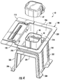
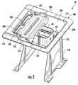
- the slidable door 120 is configured to slide from a first operational position (shown in FIG. 4 ) to a second operational position (shown in FIG. 5 ) and vice versa.
- the slidable door 120 is configured to cover an open end of the fuse compartments 300, 302 at the first operational position to prevent the fuses 104, 106 from being removed from the fuse compartments 300, 302, respectively.
- the slidable door 120 is further configured to extend over a portion of the manual service disconnect lower housing 60 at the second operational position only if the manual service disconnect upper housing 62 is previously de-coupled from the manual service disconnect lower housing 60.
- the slidable door 120 is further configured to not cover the open end of the fuse compartments 300, 302 at the second operational position such that the fuses 104, 106 are accessible to an operator.
- the slidable door 120 is configured to allow an operator to access the fuses 104, 106 only when the manual service disconnect upper housing 62 is removed from the fuse lockout assembly 50 and the slidable door 120 is at the second operational position.
- the slidable door 120 When the slidable door 120 is slid from the first operational position at least partially into the interior region 214, the slidable door 120 is configured to abut against the manual service disconnect upper housing 62 if the manual service disconnect upper housing 162 is coupled to the manual service disconnect lower housing 160 in the interior region 214, such that the slidable door 120 cannot extend to the second operational position. Further, the slidable door 120 at least partially covers the open end of the fuse compartments 300, 302 when the slidable door 120 is disposed between the first and second operational positions such that the fuses 104, 106 are not accessible by an operator. Also, the slidable door 120 at the first operational position does not interfere with the manual service disconnect upper housing 62 being de-coupled from the manual service disconnect lower housing 60 in the interior region 214.
- the slidable door 120 has a plate portion 400, a plate portion 402, and a gasket 403.
- the plate portion 402 extends from an end of the plate portion 400 and is substantially perpendicular to the plate portion 400.
- the plate portion 400 has a first side 405 and a second side 406.
- the plate portion 400 further includes edge portions 410, 412 and a groove 414 extending between the edge portions 410, 412.
- the plate portion 400 further includes edge portions 420, 422 and a groove 424 extending between the end portions 420, 422.
- the plate portion 400 further includes raised portions 430, 432, 434, 436 extending upwardly from the second side 406, and a top indentation 440 extending downwardly from the first side 405.
- the gasket 403 is coupled to the first side 405 and is generally rectangular ring-shaped.
- the gasket 403 has a central opening that receives the top indentation 440 therein.
- the gasket 403 is configured to contact the plate portion 204 of the housing 100 around the open ends of the fuse compartments 300, 302 when the slidable door 120 is at the first operational position to provide a fluid-tight seal around the open ends of the fuse compartments 300, 302.
- the gasket 403 is constructed of an elastomeric material.
- edge portions 410, 412 of the slidable door 120 are slidably received within the gap G1 between the plate portion 204 and the guide portion 330. Also, the edge portions 420, 422 are received within a gap between the plate portion 204 and the guide portion 332.
- the edge portion 410 includes a stopping surface 416 configured to abut against the stopping member 350 (shown in FIG. 13 ) when the slidable door 120 is at the second operational position. Further, the edge portion 412 includes a stopping surface 417 configured to abut against the stopping member 350 when the slidable door 120 is at the first operational position.
- the edge portion 420 includes a stopping surface 426 configured to abut against the stopping member 352 (shown in FIG. 13 ) when the slidable door 120 is at the second operational position. Further, the edge portion 422 includes a stopping surface 427 configured to abut against the stopping member 352 when the slidable door 120 is at the first operational position.
- the raised portions 430, 432, 434, 436 are configured to contact a bottom surface 441 (shown in FIG. 17 ) of the guide plate 110.
- the raised portions 430, 432, 434, 436 urge the gasket 403 of the slidable door 120 downwardly to seal against the plate portion 204 of the housing 100 when the slidable door 120 is at the first operational position.
- the top indentation 440 extends longitudinally across the slidable door 120 and provides additional rigidity to the slidable door 120.
- the plate portion 402 include apertures 450, 452 extending therethrough for receiving bolts 453, 454, respectively, therethrough.
- the bolts 453, 454 are configured to couple the slidable door 120 to the tub portion 200 at the first operational position. It should be noted that the bolts 453, 454 are removed from the apertures 450, 452 allow an operator to move the slidable door 120 from the first operational position to the second operational position.
- the mounting bracket 130 is coupled to the bottom plate 250 of the tub portion 200, and is further coupled to the lower housing portion 20.
- the mounting bracket includes leg portions 500, 502, a plate portion 504, and flange portions 506, 508.
- the leg portions 500, 502 extend downwardly from opposite ends of the plate portion 504.
- the flange portion 506 extends outwardly from the leg portion 500 and is configured to be coupled to the lower housing portion 20.
- the flange portion 508 extends outwardly from the leg portion 502 and is configured to be coupled to the lower housing portion 20.
- the plate portion 504 includes apertures extending therethrough for receiving the bolts 150, 152, 154, 156, 160, 162, 164, 166 therethrough.
- the bolts 160, 162, 164, 166 are configured to couple the plate portion 504 to the bottom plate 250 of the tub portion 200.
- the mounting bracket 130 is constructed of steel.
- the mounting bracket 130 could be constructed of another material, such as plastic or aluminum for example.
- fuse lock-out assembly 50 provides a substantial advantage over other assemblies.
- fuse lock-out assembly 50 provides a technical advantage of utilizing with the slidable door 120 that prevents access to fuse compartments unless a lower housing 60 of the manual service disconnect 48 is removed from the fuse lock-out assembly 50.
Landscapes
- Connection Of Batteries Or Terminals (AREA)
- Fuses (AREA)
- Engineering & Computer Science (AREA)
- Battery Mounting, Suspending (AREA)
- Electric Propulsion And Braking For Vehicles (AREA)
- Life Sciences & Earth Sciences (AREA)
- Sustainable Development (AREA)
- Sustainable Energy (AREA)
- Power Engineering (AREA)
- Transportation (AREA)
- Mechanical Engineering (AREA)
Abstract
Description
- The inventors herein have recognized a need for a battery pack that prevents access to battery pack fuses when a manual service disconnect is electrically coupling battery modules together within the battery pack.
- A fuse lock-out assembly for a battery pack in accordance with an exemplary embodiment is provided. The fuse lock-out assembly includes a first housing having an interior region configured to hold a manual service disconnect lower housing and a manual service disconnect upper housing therein. The fuse lock-out assembly further includes a fuse holding housing coupled to the first housing. The fuse holding housing has a first fuse compartment configured to hold a first fuse therein. The fuse lock-out assembly further includes a slidable door slidably coupled to the first housing. The slidable door is configured to slide from a first operational position to a second operational position. The slidable door is configured to cover an open end of the first fuse compartment at the first operational position to prevent the first fuse from being removed from the first fuse compartment. The slidable door is further configured to extend over a portion of the manual service disconnect lower housing at the second operational position only if the manual service disconnect upper housing is previously de-coupled from the manual service disconnect lower housing. The slidable door is further configured to not cover the open end of the first fuse compartment at the second operational position.
-
-
FIG. 1 is a schematic of an electrical vehicle having a battery pack with a fuse lock-out assembly in accordance with an exemplary embodiment; -
FIG. 2 is a schematic of the battery pack having a fuse lock-out assembly in accordance with an exemplary embodiment; -
FIG. 3 is a cross-sectional schematic of the battery pack ofFIG. 2 ; -
FIG. 4 is a schematic of the fuse lock-out assembly ofFIG. 2 having a manual service disconnect upper housing de-coupled therefrom, and having a slidable door in a first operational position covering fuse compartments; -
FIG. 5 is another schematic of the fuse-lock-out assembly ofFIG. 2 having the slidable door in a second operational position in which fuse compartments are accessible; -
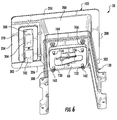
FIG. 6 is another schematic of the fuse-lock-out assembly ofFIG. 2 ; -
FIG. 7 is an enlarged schematic of a portion of the fuse-lock-out assembly ofFIG. 2 having a slidable door in a first operational position covering fuse compartments; -
FIG. 8 is another enlarged schematic of a portion of the fuse-lock-out assembly ofFIG. 2 having a slidable door in a first operational position covering fuse compartments; -
FIG. 9 is a top view of the fuse lock-out assembly ofFIG. 2 having the sliding door in the second operational position in which the fuse compartments are accessible; -
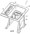
FIG. 10 is a schematic of the fuse lock-out assembly ofFIG. 2 without the slidable door being shown; -
FIG. 11 is a schematic of a housing utilized in the fuse lock-out assembly ofFIG. 2 ; -
FIG. 12 is a schematic of a fuse holding housing utilized in the fuse lock-out assembly ofFIG. 2 ; -
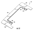
FIG. 13 is a schematic of a guide plate utilized in the fuse lock-out assembly ofFIG. 2 ; -
FIG. 14 is another schematic of the guide plate ofFIG. 13 ; -
FIG. 15 is a schematic of a slidable door utilized in the fuse lock-out assembly ofFIG. 2 ; -
FIG. 16 is another schematic of the slidable door ofFIG. 15 ; -
FIG. 17 is a cross-sectional schematic of a portion of the fuse lock-out assembly ofFIG. 2 ; -
FIG. 18 is an enlarged schematic of a portion of the fuse lock-out assembly ofFIG. 2 having a first stopping member configured to stop movement of the slidable door at the second operational position; and -
FIG. 19 is an enlarged schematic of a portion of the fuse lock-out assembly ofFIG. 2 having a second stopping member configured to stop movement of the slidable door at the second operational position. - Referring to
FIGS. 1 and2 , an electric vehicle 4 is illustrated. The electric vehicle 4 includes abattery pack 10, a vehicleelectrical system 11,auxiliary loads computer 14. - Referring to
FIGS. 1-5 , thebattery pack 10 in accordance with an exemplary embodiment provides electrical power to the vehicleelectrical system 11, and theauxiliary loads battery pack 10 includes alower housing portion 20, anupper housing portion 30,battery modules manual service disconnect 48,contactors out assembly 50 in accordance with an exemplary embodiment. An advantage of thebattery pack 10 is thebattery pack 10 utilizes the fuse lock-out assembly 50 with a slidable door 120 (shown inFIG. 4 ) that prevents access to fuse compartments unless anupper housing 62 of themanual service disconnect 48 is removed from the fuse lock-out assembly 50. For purposes of understanding, a fuse is "accessible" if the fuse can be removed from a fuse compartment by an operator or disposed into the fuse compartment by the operator. - Referring to
FIG. 1 , thecontactor 52 is electrically coupled between thenode 54 and thebattery module 40. Further, thebattery module 40 is electrically coupled in series between thecontactor 52 and thefuse 63 of themanual service disconnect 48. Also, thebattery module 42 is electrically coupled between thefuse 63 of themanual service disconnect 48 and thecontactor 53. Thecontactor 53 is electrically coupled in series between thebattery module 42 and thenode 55. The vehicleelectrical system 11 is electrically coupled between thenodes contactors computer 14, and thefuse 63 has a non-blown state and is in series with thebattery modules battery modules electrical system 11. Also, when thecontactors computer 14, and thefuses battery modules auxiliary loads - It is noted that if the manual service disconnect
upper housing 62 having thefuse 63 is removed from thebattery pack 10 by an operator, the operational voltage supplied by thebattery modules - Referring to
FIGS. 1 and2 , theupper housing portion 30 is configured to be coupled to thelower housing portion 20. Thelower housing portion 20 is configured to hold thebattery modules assembly 50 thereon. Theupper housing portion 30 and thelower housing portion 20 define an interior region configured to hold thebattery modules upper housing portion 30 has an aperture extending therethrough in which a portion of the fuse lock-outassembly 50 extends therethrough. In one exemplary embodiment, theupper housing portion 30 and thelower housing portion 20 are constructed of steel. Of course, in an alternative embodiment, theupper housing portion 30 and thelower housing portion 20 could be constructed of other materials such as aluminum or plastic for example. - Referring to
FIG. 1 , thebattery modules fuse 63 of themanual service disconnect 48 and thecontactors battery modules battery modules - Referring to
FIGS. 1-3 , themanual service disconnect 48 is configured to selectively electrically to couple thebattery modules battery modules service disconnect assembly 48 has the manual service disconnectlower housing 60, the manual service disconnectupper housing 62, and thefuse 63 disposed in theupper housing 62. Theupper housing 62 is configured to be removably coupled to thelower housing 60. A portion of the lower housing 60 (shown inFIG. 6 ) is disposed through a central aperture 252 (shown inFIG. 11 ) of thehousing 100. Thelower housing 60 is coupled to a bottom plate 250 (shown inFIG. 11 ) of thehousing 100 utilizingbolts bolts bottom plate 250, and thebottom plate 250, and a portion of thelower housing 60. Corresponding nuts are coupled to the bolts 150-156 proximate to a bottom surface of thelower housing 60. When theupper housing 62 is coupled to thelower housing 60, thebattery modules upper housing 62 is de-coupled from thelower housing 60, thebattery modules - Referring to
FIGS. 1, 4-6 and 17 , the fuse lock-out assembly 50 utilizes aslidable door 120 that prevents access to fuse compartments in the fuse holding housing 102 (shown inFIG. 17 ) unless the manual service disconnectupper housing 60 is de-coupled from the manual service disconnectlower housing 62. The fuse lock-out assembly 50 includes ahousing 100, thefuse holding housing 102, aguide plate 110, theslidable door 120, abracket 130, agasket 142,bolts bolts - Referring to
FIGS. 4 ,5 and11 , thehousing 100 is configured to hold themanual service disconnect 48 therein. Thehousing 100 is further configured to hold thefuse holding housing 102, theguide plate 110, and theslidable door 120 thereon. Thehousing 100 includes atub portion 200, aplate portion 204, andflange portions - The
tub portion 200 defines an interior region 214 (shown inFIG. 5 ) configured to hold the manual service disconnectlower housing 60 and the manual service disconnectupper housing 62 therein. Thetub portion 200 hasside walls bottom plate 250 coupled to theside walls tub portion 200 has an open end opposite to thebottom plate 250. Thebottom plate 250 has acentral aperture 252 extending therethrough configured to receive a portion of the manual service disconnectlower housing 60 therethrough. Referring toFIGS. 6 and11 , the bottom plate further includesapertures bolts - The
plate portion 204 extends outwardly from a peripheral edge of thetub portion 200 proximate to an open end of thetub portion 200. Theplate portion 204 has afirst side 270 and asecond side 272 and hasapertures apertures fuse holding housing 102. - Referring to
FIGS. 2 and11 , theflange portion 206 extends outwardly from anedge 274 of theplate portion 204, and further extends from theside wall 230 of thetub portion 200. Theflange portion 208 extends outwardly from theside wall 232 of thetub portion 200. Theflange portion 210 extends outwardly from anedge 276 of theplate portion 204, and further extends from theside wall 234 of thetub portion 200. Theflange portions upper housing portion 30. - Referring to
FIGS. 1, 4-6 and 12 , thefuse holding housing 102 is configured to hold thefuses fuse holding housing 102 includes fuse compartments 300, 302 (shown inFIG. 5 ) and aperipheral flange 304 extending around a periphery of open ends of the fuse compartments 300, 302. The fuse compartments 300, 302 are configured to hold thefuses guide portions guide plate 110. Thefuse compartment 300 may include first and second electrical adapters that are coupled to ends of thefuse 104. Further, thefuse compartment 302 may include first and second electrical adapters that are coupled to ends of thefuse 106. Further, in thefuse compartment 300, electrical cables may extend from the first and second electrical adapters through apertures in thefuse compartment 300. Also, in thefuse compartment 302, electrical cables may extend from the first and second electrical adapters through apertures in thefuse compartment 302. Referring toFIG. 6 , theperipheral flange 304 is coupled to thesecond side 272 of thehousing 100. Referring toFIGS. 11 and12 , thefuse compartment 300 communicates with theaperture 280 in theplate portion 204 of thehousing 100. Further, thefuse compartment 302 communicates with theaperture 282 in theplate portion 204 of thehousing 100. In one exemplary embodiment, thefuse holding housing 102 is constructed of plastic. Of course, in an alternative embodiment, thefuse holding housing 102 could be constructed of other materials. - Referring to
FIGS. 5 ,13 ,14 ,18 and19 , theguide plate 110 is configured to guide movement of theslidable door 120 relative to thehousing 100. Theguide plate 110 includesguide portions flange portions guide portions flange portion 342 extends between the end portions of theguide portions flange portion 340 is coupled to theguide portion 330 and extends generally parallel to theguide portion 330. Theflange portion 344 is coupled to theguide portion 332 and extends generally parallel to theguide portion 332. Theflange portions plate portion 204 of thehousing 100. In one exemplary embodiment, theguide plate 110 is constructed of steel. Of course, in an alternative embodiment, theguide plate 110 could be constructed of other materials, such as plastic of aluminum for example. - Referring to
FIGS. 13 ,14 and17 , theguide portion 330 and theplate portion 204 of thehousing 100 define a gap G1 therebetween. The gap G1 is configured to receive a portion of theslidable door 120 therein. Theguide portion 330 includes a stoppingmember 350 that extends into the gap G1. When theslidable door 120 is at the second operational position (shown inFIG. 5 ) and thefuses member 350 abuts against a stopping surface 416 (shown inFIGS. 18 and 25 ) of anedge portion 410 of theslidable door 120. The stoppingmember 350 prevents theslidable door 120 from being slidably removed from the fuse lock-out assembly 50. Alternately, when theslidable door 120 is at the first operational position (shown inFIG. 4 ) and thefuses member 350 abuts against a stopping surface 417 (shown inFIG. 15 ) of anedge portion 412 of theslidable door 120. - The
guide portion 332 and theplate portion 204 of thehousing 100 define a gap therebetween. The gap between theguide portion 332 and theplate portion 204 is configured to receive a portion of theslidable door 120 therein. Theguide portion 332 includes a stoppingmember 352 that extends into the gap. When theslidable door 120 is at the second operational position and thefuses member 352 abuts against a stopping surface 426 (shown inFIGS. 15 and19 ) of anedge portion 420 of theslidable door 120. The stoppingmember 350 prevents theslidable door 120 from being slidably removed from the fuse lock-out assembly 50. Alternately, when theslidable door 120 is at the first operational position and thefuses member 352 abuts against a stopping surface 427 (shown inFIG. 15 ) of anedge portion 422 of theslidable door 120. - Referring to
FIGS. 15-19 , theslidable door 120 is at least partially disposed within the gap G1 and the gap between theguide portion 332 and theplate portion 204. Theslidable door 120 is configured to slide from a first operational position (shown inFIG. 4 ) to a second operational position (shown inFIG. 5 ) and vice versa. Theslidable door 120 is configured to cover an open end of the fuse compartments 300, 302 at the first operational position to prevent thefuses slidable door 120 is further configured to extend over a portion of the manual service disconnectlower housing 60 at the second operational position only if the manual service disconnectupper housing 62 is previously de-coupled from the manual service disconnectlower housing 60. Theslidable door 120 is further configured to not cover the open end of the fuse compartments 300, 302 at the second operational position such that thefuses slidable door 120 is configured to allow an operator to access thefuses upper housing 62 is removed from thefuse lockout assembly 50 and theslidable door 120 is at the second operational position. - When the
slidable door 120 is slid from the first operational position at least partially into theinterior region 214, theslidable door 120 is configured to abut against the manual service disconnectupper housing 62 if the manual service disconnectupper housing 162 is coupled to the manual service disconnectlower housing 160 in theinterior region 214, such that theslidable door 120 cannot extend to the second operational position. Further, theslidable door 120 at least partially covers the open end of the fuse compartments 300, 302 when theslidable door 120 is disposed between the first and second operational positions such that thefuses slidable door 120 at the first operational position does not interfere with the manual service disconnectupper housing 62 being de-coupled from the manual service disconnectlower housing 60 in theinterior region 214. - The
slidable door 120 has aplate portion 400, aplate portion 402, and agasket 403. Theplate portion 402 extends from an end of theplate portion 400 and is substantially perpendicular to theplate portion 400. Theplate portion 400 has afirst side 405 and a second side 406. Theplate portion 400 further includesedge portions groove 414 extending between theedge portions plate portion 400 further includesedge portions groove 424 extending between theend portions plate portion 400 further includes raisedportions top indentation 440 extending downwardly from thefirst side 405. Thegasket 403 is coupled to thefirst side 405 and is generally rectangular ring-shaped. Thegasket 403 has a central opening that receives thetop indentation 440 therein. Thegasket 403 is configured to contact theplate portion 204 of thehousing 100 around the open ends of the fuse compartments 300, 302 when theslidable door 120 is at the first operational position to provide a fluid-tight seal around the open ends of the fuse compartments 300, 302. Thegasket 403 is constructed of an elastomeric material. - The
edge portions slidable door 120 are slidably received within the gap G1 between theplate portion 204 and theguide portion 330. Also, theedge portions plate portion 204 and theguide portion 332. - The
edge portion 410 includes a stoppingsurface 416 configured to abut against the stopping member 350 (shown inFIG. 13 ) when theslidable door 120 is at the second operational position. Further, theedge portion 412 includes a stoppingsurface 417 configured to abut against the stoppingmember 350 when theslidable door 120 is at the first operational position. - The
edge portion 420 includes a stoppingsurface 426 configured to abut against the stopping member 352 (shown inFIG. 13 ) when theslidable door 120 is at the second operational position. Further, theedge portion 422 includes a stoppingsurface 427 configured to abut against the stoppingmember 352 when theslidable door 120 is at the first operational position. - The raised
portions FIG. 17 ) of theguide plate 110. The raisedportions gasket 403 of theslidable door 120 downwardly to seal against theplate portion 204 of thehousing 100 when theslidable door 120 is at the first operational position. Thetop indentation 440 extends longitudinally across theslidable door 120 and provides additional rigidity to theslidable door 120. - Referring to
FIGS. 7 and15 , theplate portion 402 includeapertures bolts bolts slidable door 120 to thetub portion 200 at the first operational position. It should be noted that thebolts apertures slidable door 120 from the first operational position to the second operational position. - Referring to
FIGS. 3 ,4 ,6 and11 , the mountingbracket 130 is coupled to thebottom plate 250 of thetub portion 200, and is further coupled to thelower housing portion 20. The mounting bracket includesleg portions plate portion 504, andflange portions leg portions plate portion 504. Theflange portion 506 extends outwardly from theleg portion 500 and is configured to be coupled to thelower housing portion 20. Also, theflange portion 508 extends outwardly from theleg portion 502 and is configured to be coupled to thelower housing portion 20. Theplate portion 504 includes apertures extending therethrough for receiving thebolts bolts plate portion 504 to thebottom plate 250 of thetub portion 200. In one exemplary embodiment, the mountingbracket 130 is constructed of steel. Of course, in an alternative embodiment, the mountingbracket 130 could be constructed of another material, such as plastic or aluminum for example. - The fuse lock-out assembly provides a substantial advantage over other assemblies. In particular, fuse lock-
out assembly 50 provides a technical advantage of utilizing with theslidable door 120 that prevents access to fuse compartments unless alower housing 60 of themanual service disconnect 48 is removed from the fuse lock-out assembly 50. - While the claimed invention has been described in detail in connection with only a limited number of embodiments, it should be readily understood that the invention is not limited to such disclosed embodiments. Rather, the claimed invention can be modified to incorporate any number of variations, alterations, substitutions or equivalent arrangements not heretofore described, but which are commensurate with the spirit and scope of the invention. Additionally, while various embodiments of the claimed invention have been described, it is to be understood that aspects of the invention may include only some of the described embodiments. Accordingly, the claimed invention is not to be seen as limited by the foregoing description.
Claims (15)
- A fuse lock-out assembly for a battery pack, comprising:a first housing having an interior region configured to hold a manual service disconnect lower housing and a manual service disconnect upper housing therein;a fuse holding housing coupled to the first housing, the fuse holding housing having a first fuse compartment configured to hold a first fuse therein;a slidable door being slidably coupled to the first housing, the slidable door configured to slide from a first operational position to a second operational position;the slidable door configured to cover an open end of the first fuse compartment at the first operational position to prevent the first fuse from being removed from the first fuse compartment; andthe slidable door further configured to extend over a portion of the manual service disconnect lower housing at the second operational position only if the manual service disconnect upper housing is previously de-coupled from the manual service disconnect lower housing, the slidable door further configured to not cover the open end of the first fuse compartment at the second operational position.
- The fuse lock-out assembly of claim 1, wherein the slidable door at the first operational position does not interfere with the manual service disconnect upper housing being de-coupled from the manual service disconnect lower housing in the interior region.
- The fuse lock-out assembly of claim 1, wherein when the slidable door is slidable from the first operational position at least partially into the interior region, the slidable door is configured to abut against the manual service disconnect upper housing if the manual service disconnect upper housing is coupled to the manual service disconnect lower housing in the interior region, such that the slidable door cannot extend to the second operational position.
- The fuse lock-out assembly of claim 3, wherein the slidable door at least partially covers the open end of the first fuse compartment when the slidable door is disposed between the first and second operational positions such that the first fuse is not accessible.
- The fuse lock-out assembly of claim 1, wherein the first housing has a tub portion and a plate portion, the plate portion extending outwardly from a peripheral edge of the tub portion proximate to an open end of the tub portion, the tub portion defining the interior region that is configured to hold the manual service disconnect lower housing and the manual service disconnect upper housing therein, the plate portion having a first side and a second side and having a first aperture extending therethrough.
- The fuse lock-out assembly of claim 5, further comprising a mounting bracket coupled to a bottom plate of the tub portion.
- The fuse lock-out assembly of claim 5, wherein a width of the slidable door is less than width of the interior region of the tub portion.
- The fuse lock-out assembly of claim 5, wherein the fuse holding housing is coupled to the second side of the plate portion of the first housing, the fuse holding housing having the first fuse compartment communicating with the first aperture in the plate portion of the first housing.
- The fuse lock-out assembly of claim 8, further comprising a guide plate coupled to the first side of the plate portion of the first housing, the guide plate having first and second guide portions, the first fuse compartment being disposed between the first and second guide portions, the first guide portion and the plate portion having a first gap therebetween, the second guide portion and the plate portion having a second gap therebetween.
- The fuse lock-out assembly of claim 9, wherein the slidable door is at least partially disposed within the first and second gaps.
- The fuse lock-out assembly of claim 9, wherein the fuse holding housing further includes a second fuse compartment configured to hold a second fuse therein and being disposed between the first and second guide portions, the plate portion further having a second aperture extending therethrough, the second fuse compartment communicating with the second aperture; and
the slidable door further configured to cover an open end of the second fuse compartment at the first operational position to prevent the second fuse from being removed from the second fuse compartment. - The fuse lock-out assembly of claim 9, wherein the first guide portion has a first stopping member extending downwardly therefrom and into the first gap, the slidable door having a first edge portion that is configured to contact the first stopping member when the slidable door is at the second operational position.
- The fuse lock-out assembly of claim 12, wherein the first stopping member prevents the slidable door from being slidably removed from the fuse lock-out assembly.
- The fuse lock-out assembly of claim 12, wherein the second guide portion has a second stopping member extending downwardly therefrom and into the second gap, the slidable door having a second edge portion that is configured to contact the second stopping member when the slidable door is at the second operational position.
- The fuse lock-out assembly of claim 1, wherein the manual service disconnect upper housing is removably coupled to the manual service disconnect lower housing.
Applications Claiming Priority (3)
| Application Number | Priority Date | Filing Date | Title |
|---|---|---|---|
| US201361863587P | 2013-08-08 | 2013-08-08 | |
| US14/011,428 US9251985B2 (en) | 2013-08-08 | 2013-08-27 | Fuse lock-out assembly for a battery pack |
| PCT/KR2014/007348 WO2015020467A1 (en) | 2013-08-08 | 2014-08-08 | Fuse lock-out assembly for battery pack |
Publications (3)
| Publication Number | Publication Date |
|---|---|
| EP3012854A1 true EP3012854A1 (en) | 2016-04-27 |
| EP3012854A4 EP3012854A4 (en) | 2016-07-06 |
| EP3012854B1 EP3012854B1 (en) | 2023-03-15 |
Family
ID=52448135
Family Applications (1)
| Application Number | Title | Priority Date | Filing Date |
|---|---|---|---|
| EP14834878.2A Active EP3012854B1 (en) | 2013-08-08 | 2014-08-08 | Fuse lock-out assembly for battery pack |
Country Status (6)
| Country | Link |
|---|---|
| US (1) | US9251985B2 (en) |
| EP (1) | EP3012854B1 (en) |
| JP (1) | JP6273359B2 (en) |
| KR (1) | KR101748803B1 (en) |
| CN (1) | CN105408982B (en) |
| WO (1) | WO2015020467A1 (en) |
Cited By (1)
| Publication number | Priority date | Publication date | Assignee | Title |
|---|---|---|---|---|
| DE102022108831A1 (en) | 2022-04-12 | 2023-10-12 | Dr. Ing. H.C. F. Porsche Aktiengesellschaft | Automotive traction battery assembly |
Families Citing this family (11)
| Publication number | Priority date | Publication date | Assignee | Title |
|---|---|---|---|---|
| US9847610B2 (en) | 2014-01-16 | 2017-12-19 | Ford Global Technologies, Llc | Electric vehicle service disconnect position indicator |
| KR102666374B1 (en) | 2017-01-23 | 2024-05-17 | 삼성에스디아이 주식회사 | Manual Service Disconnect for Battery System |
| CN109003945A (en) * | 2018-08-24 | 2018-12-14 | 常州普莱德新能源电池科技有限公司 | A kind of bracket and battery case |
| JP7276683B2 (en) * | 2019-04-24 | 2023-05-18 | マツダ株式会社 | Vehicle battery system |
| KR102819524B1 (en) * | 2020-03-03 | 2025-06-12 | 현대자동차주식회사 | Fuse box for battery of vehicle |
| CN113543568B (en) * | 2020-04-21 | 2024-08-20 | 罗伯特·博世有限公司 | Electrical components |
| KR102820188B1 (en) * | 2020-05-13 | 2025-06-13 | 주식회사 엘지에너지솔루션 | Battery Pack With Fuse-Box Bracket of Preventing Short Circuit |
| CN217405652U (en) | 2022-01-24 | 2022-09-09 | 阳光储能技术有限公司 | Fuse mounting structure and battery system |
| US12157424B2 (en) * | 2022-08-09 | 2024-12-03 | Ford Global Technologies, Llc | Electrified vehicle traction powertrain module having externally integrated fuse box |
| US11990306B2 (en) * | 2022-08-09 | 2024-05-21 | Ford Global Technologies, Llc | Electrified vehicle traction powertrain module having removably insertable fuse box |
| JP2024035311A (en) * | 2022-09-02 | 2024-03-14 | 株式会社Aescジャパン | battery pack |
Family Cites Families (65)
| Publication number | Priority date | Publication date | Assignee | Title |
|---|---|---|---|---|
| US1966716A (en) | 1932-01-25 | 1934-07-17 | Frank Adam Electric Co | Circuit interrupting and protecting apparatus |
| US2072729A (en) * | 1935-09-14 | 1937-03-02 | Nat Electric Prod Corp | Safety switch |
| US2186813A (en) * | 1936-06-29 | 1940-01-09 | Frank Adam Electric Co | Circuit interrupting and protecting device |
| JPS58104553U (en) * | 1982-01-11 | 1983-07-16 | 松下電器産業株式会社 | Fuse storage device |
| USD298123S (en) | 1985-01-22 | 1988-10-18 | Cambridge Electric Industries plc | Fuse holder |
| US4778959A (en) * | 1987-04-27 | 1988-10-18 | General Electric Company | Fused disconnect switch |
| US4806118A (en) * | 1988-01-19 | 1989-02-21 | General Motors Corporation | Fuse package |
| US4966561A (en) | 1989-05-31 | 1990-10-30 | Connectron, Inc. | Fuse holders |
| JPH056302A (en) | 1991-06-28 | 1993-01-14 | Hokkaido Nippon Denki Software Kk | Memory management system |
| US5186637A (en) * | 1991-09-27 | 1993-02-16 | Connectron, Inc. | Lockable electrical apparatus |
| KR940003113B1 (en) * | 1991-10-28 | 1994-04-13 | 주식회사 신도리코 | Manual Feeder for Continuous Copying |
| US5556305A (en) | 1995-04-07 | 1996-09-17 | Yazaki Corporation | Fuse lockout mechanism |
| US5700165A (en) * | 1995-12-11 | 1997-12-23 | General Motors Corporation | Fused high ampacity electrical quick disconnect |
| US5847338A (en) | 1996-02-15 | 1998-12-08 | Sumitomo Wiring Systems, Ltd. | Breaker device |
| US5842560A (en) | 1996-02-15 | 1998-12-01 | Sumitomo Wiring Systems, Ltd. | Breaker device |
| US5841337A (en) | 1997-01-17 | 1998-11-24 | Cooper Technologies Company | Touch safe fuse module and holder |
| US5963420A (en) * | 1997-09-22 | 1999-10-05 | Eaton Corporation | Interlock bypass |
| US6054915A (en) | 1998-02-17 | 2000-04-25 | Cooper Industries, Inc. | Compact touchsafe fuseholder with removable fuse carrier |
| FI104522B (en) | 1998-04-28 | 2000-02-15 | Abb Control Oy | Fused switch |
| US5973418A (en) * | 1998-05-05 | 1999-10-26 | Cooper Technologies Company | Pull-out high current switch |
| GB9825900D0 (en) | 1998-11-27 | 1999-01-20 | Schneider Ltd | Fuse handler |
| JP2000223001A (en) | 1999-01-27 | 2000-08-11 | Yazaki Corp | Power cut-off device |
| JP3566573B2 (en) | 1999-03-01 | 2004-09-15 | 矢崎総業株式会社 | Power shut-off device |
| US6157287A (en) | 1999-03-03 | 2000-12-05 | Cooper Technologies Company | Touch safe fuse module and holder |
| JP2000311576A (en) | 1999-04-27 | 2000-11-07 | Yazaki Corp | Power cut-off device |
| JP3612439B2 (en) | 1999-05-06 | 2005-01-19 | 矢崎総業株式会社 | Power shut-off device |
| JP3657160B2 (en) | 1999-08-18 | 2005-06-08 | 株式会社オートネットワーク技術研究所 | Breaker device |
| JP2001126593A (en) | 1999-08-18 | 2001-05-11 | Auto Network Gijutsu Kenkyusho:Kk | Breaker device |
| US6407656B1 (en) | 1999-08-18 | 2002-06-18 | Autonetworks Technologies, Ltd. | Breaker device |
| US6587028B2 (en) | 2000-07-07 | 2003-07-01 | Cooper Technologies Company | Fused disconnect switch |
| US6784783B2 (en) | 2000-10-24 | 2004-08-31 | Cooper Technologies Company | Compact fused disconnect switch |
| US6853289B2 (en) | 2000-10-24 | 2005-02-08 | Cooper Technologies Company | Fuse handle for fused disconnect switch |
| US6650222B2 (en) * | 2000-12-07 | 2003-11-18 | Cooper Technologies Company | Modular fuseholder |
| JP3964143B2 (en) * | 2001-02-13 | 2007-08-22 | 株式会社オートネットワーク技術研究所 | Breaker device |
| JP3976511B2 (en) * | 2001-03-26 | 2007-09-19 | 矢崎総業株式会社 | Battery cover |
| US6773307B2 (en) * | 2001-06-29 | 2004-08-10 | Delphi Technologies, Inc. | High current manual disconnect system |
| US6692291B2 (en) * | 2002-05-02 | 2004-02-17 | Ching-Hsiung Chen | Cable piercing device for use with a plug |
| JP4272037B2 (en) | 2003-11-10 | 2009-06-03 | 矢崎総業株式会社 | Lever fitting type power circuit breaker |
| US7019612B2 (en) * | 2003-12-16 | 2006-03-28 | Chia Ho Lin | Fuse seat for filter |
| DE102004031110B4 (en) | 2004-06-28 | 2008-02-14 | Wöhner GmbH & Co. KG Elektrotechnische Systeme | safety switch |
| US7244148B2 (en) * | 2004-07-23 | 2007-07-17 | Ford Global Technologies Llc | Circuit disconnect assembly |
| EP1779141A2 (en) | 2004-08-13 | 2007-05-02 | Koninklijke Philips Electronics N.V. | Solid state radiation detector packaging technique |
| JP4690843B2 (en) | 2005-10-06 | 2011-06-01 | 古河電気工業株式会社 | Breaker device |
| JP4606356B2 (en) | 2006-03-16 | 2011-01-05 | 矢崎総業株式会社 | Fuse and power circuit breaker provided with the fuse |
| DE102006022374B4 (en) | 2006-05-12 | 2014-07-03 | Wöhner GmbH & Co. KG Elektrotechnische Systeme | switchgear |
| JP4875993B2 (en) * | 2007-01-17 | 2012-02-15 | 日産自動車株式会社 | Power supply circuit connection device |
| DE102007023234A1 (en) | 2007-05-18 | 2008-11-20 | Kostal Kontakt Systeme Gmbh | Circuit breaker for a motor vehicle |
| KR20080107231A (en) * | 2007-06-05 | 2008-12-10 | 한국제이에스티알앤디센터(주) | Connector assembly of high voltage battery pack |
| JP5014012B2 (en) | 2007-07-31 | 2012-08-29 | 矢崎総業株式会社 | Power circuit breaker |
| EP2112675B1 (en) | 2008-04-01 | 2014-11-12 | Wöhner GmbH & Co. KG Elektrotechnische Systeme | Fuse switch disconnector |
| US7985098B2 (en) * | 2008-11-20 | 2011-07-26 | Tyco Electronics Corporation | Fuse connector assembly |
| US7893809B2 (en) | 2009-02-19 | 2011-02-22 | Tyco Electronics Corporation | Service disconnect assembly for a high voltage electronic module |
| IT1394694B1 (en) * | 2009-04-17 | 2012-07-13 | Palazzoli Spa | FUSE HOLDER DEVICE, PARTICULARLY FOR INTERLOCKED SOCKETS AND ELECTRIC APPLIANCES IN GENERAL |
| US8098126B2 (en) * | 2009-04-22 | 2012-01-17 | Lg Chem, Ltd. | High voltage service disconnect assembly |
| US8221165B2 (en) * | 2009-12-22 | 2012-07-17 | Tyco Electronics Corporation | Connector assembly with an integrated fuse |
| US8288031B1 (en) | 2011-03-28 | 2012-10-16 | Lg Chem, Ltd. | Battery disconnect unit and method of assembling the battery disconnect unit |
| US8562368B2 (en) * | 2011-07-07 | 2013-10-22 | Tyco Electronics Corporation | Service disconnect assembly |
| US8597049B2 (en) * | 2011-07-19 | 2013-12-03 | Cooper Technologies Company | Modular open fuse holder |
| WO2013059611A2 (en) * | 2011-10-21 | 2013-04-25 | Cobasys, Llc | Modular battery disconnect unit |
| KR101198620B1 (en) * | 2011-11-14 | 2012-11-07 | 주식회사 경신 | Battery Fuse Terminal for commercial vehicles |
| DE102012200750B4 (en) * | 2012-01-19 | 2013-12-19 | Continental Automotive Gmbh | Functional unit for an electrical energy storage system with a movable protective cover, electric energy storage system and electromobile motor vehicle |
| DE102013001391A1 (en) * | 2012-01-26 | 2013-07-25 | Lear Corporation | Electrical connector for use in battery separation unit, has connector body comprising two electrical connectors and fuse, which is supported on connector body, where one of electrical connectors is supported by fuse |
| US9214310B2 (en) * | 2012-10-29 | 2015-12-15 | Tyco Electronics Corporation | Service disconnect assembly |
| US9160127B2 (en) * | 2012-12-28 | 2015-10-13 | Fca Us Llc | Insert for battery electric vehicle (BEV) service disconnect |
| US9509096B2 (en) * | 2013-01-10 | 2016-11-29 | Tyco Electronics Corporation | Manual service disconnects for battery systems |
-
2013
- 2013-08-27 US US14/011,428 patent/US9251985B2/en active Active
-
2014
- 2014-08-08 WO PCT/KR2014/007348 patent/WO2015020467A1/en not_active Ceased
- 2014-08-08 EP EP14834878.2A patent/EP3012854B1/en active Active
- 2014-08-08 JP JP2016529722A patent/JP6273359B2/en active Active
- 2014-08-08 CN CN201480042005.9A patent/CN105408982B/en active Active
- 2014-08-08 KR KR1020167000970A patent/KR101748803B1/en active Active
Cited By (1)
| Publication number | Priority date | Publication date | Assignee | Title |
|---|---|---|---|---|
| DE102022108831A1 (en) | 2022-04-12 | 2023-10-12 | Dr. Ing. H.C. F. Porsche Aktiengesellschaft | Automotive traction battery assembly |
Also Published As
| Publication number | Publication date |
|---|---|
| JP6273359B2 (en) | 2018-01-31 |
| CN105408982B (en) | 2017-09-15 |
| US9251985B2 (en) | 2016-02-02 |
| WO2015020467A1 (en) | 2015-02-12 |
| KR101748803B1 (en) | 2017-06-19 |
| EP3012854B1 (en) | 2023-03-15 |
| EP3012854A4 (en) | 2016-07-06 |
| KR20160026992A (en) | 2016-03-09 |
| JP2016528687A (en) | 2016-09-15 |
| US20150042442A1 (en) | 2015-02-12 |
| CN105408982A (en) | 2016-03-16 |
Similar Documents
| Publication | Publication Date | Title |
|---|---|---|
| US9251985B2 (en) | Fuse lock-out assembly for a battery pack | |
| US9957736B2 (en) | Electrical vehicle latch having a fluid tight electrical housing | |
| KR102610042B1 (en) | integrated high voltage junction unit for electric vehicle | |
| US10003157B2 (en) | Service plug unit, device unit, and power cutting-off system for electric car comprising same | |
| KR101405623B1 (en) | Electric box for vehicle | |
| US20140329121A1 (en) | Power supply device, circuit board, and vehicle and storage battery device equipped with power supply device | |
| US10160335B2 (en) | Power distributing apparatus of vehicle | |
| CN102396044A (en) | High Voltage Service Breakout Assembly | |
| KR20140077811A (en) | Battery module | |
| EP2624332B1 (en) | Pouring structure for battery pack | |
| CN110382283B (en) | Stationary energy plant | |
| KR20220159747A (en) | Fuse block for vehicle | |
| US20130196521A1 (en) | Battery pack busbar module | |
| KR102666374B1 (en) | Manual Service Disconnect for Battery System | |
| EP2437345B1 (en) | Battery pack for electric vehicles | |
| US20200412108A1 (en) | Switchgear | |
| KR101876860B1 (en) | Left and right closing junction block cover | |
| CN108962641A (en) | Current switch element and the electric switch equipment including it can be removed | |
| CN219759830U (en) | Battery device | |
| JP6118051B2 (en) | Service plug infiltration prevention structure | |
| JP6068884B2 (en) | Battery pack terminal protection cover | |
| US2987357A (en) | Battery charger mounting for industrial trucks | |
| KR20170003536U (en) | Relay | |
| JP2023506718A (en) | Automotive battery assembly with interlocking means for protecting two connection terminals | |
| EP2645394B1 (en) | Power circuit interrupting device |
Legal Events
| Date | Code | Title | Description |
|---|---|---|---|
| PUAI | Public reference made under article 153(3) epc to a published international application that has entered the european phase |
Free format text: ORIGINAL CODE: 0009012 |
|
| 17P | Request for examination filed |
Effective date: 20160120 |
|
| AK | Designated contracting states |
Kind code of ref document: A1 Designated state(s): AL AT BE BG CH CY CZ DE DK EE ES FI FR GB GR HR HU IE IS IT LI LT LU LV MC MK MT NL NO PL PT RO RS SE SI SK SM TR |
|
| AX | Request for extension of the european patent |
Extension state: BA ME |
|
| A4 | Supplementary search report drawn up and despatched |
Effective date: 20160602 |
|
| RIC1 | Information provided on ipc code assigned before grant |
Ipc: H01H 9/20 20060101AFI20160527BHEP Ipc: H01R 13/68 20060101ALN20160527BHEP Ipc: H01H 85/25 20060101ALN20160527BHEP Ipc: H01H 85/20 20060101ALI20160527BHEP Ipc: H01H 85/22 20060101ALI20160527BHEP Ipc: H01H 85/54 20060101ALI20160527BHEP Ipc: H01H 85/02 20060101ALN20160527BHEP Ipc: H01H 9/10 20060101ALN20160527BHEP |
|
| DAX | Request for extension of the european patent (deleted) | ||
| STAA | Information on the status of an ep patent application or granted ep patent |
Free format text: STATUS: EXAMINATION IS IN PROGRESS |
|
| 17Q | First examination report despatched |
Effective date: 20180709 |
|
| RAP1 | Party data changed (applicant data changed or rights of an application transferred) |
Owner name: LG ENERGY SOLUTION LTD. |
|
| RAP3 | Party data changed (applicant data changed or rights of an application transferred) |
Owner name: LG ENERGY SOLUTION, LTD. |
|
| REG | Reference to a national code |
Ref country code: DE Ref legal event code: R079 Ref document number: 602014086475 Country of ref document: DE Free format text: PREVIOUS MAIN CLASS: H01H0085200000 Ipc: H01H0009200000 |
|
| RIC1 | Information provided on ipc code assigned before grant |
Ipc: H01R 13/68 20110101ALN20221124BHEP Ipc: H01H 85/02 20060101ALN20221124BHEP Ipc: H01H 85/25 20060101ALN20221124BHEP Ipc: H01H 9/10 20060101ALN20221124BHEP Ipc: H01H 85/54 20060101ALI20221124BHEP Ipc: H01H 85/22 20060101ALI20221124BHEP Ipc: H01H 85/20 20060101ALI20221124BHEP Ipc: H01H 9/20 20060101AFI20221124BHEP |
|
| GRAP | Despatch of communication of intention to grant a patent |
Free format text: ORIGINAL CODE: EPIDOSNIGR1 |
|
| STAA | Information on the status of an ep patent application or granted ep patent |
Free format text: STATUS: GRANT OF PATENT IS INTENDED |
|
| RIC1 | Information provided on ipc code assigned before grant |
Ipc: H01R 13/68 20110101ALN20221206BHEP Ipc: H01H 85/02 20060101ALN20221206BHEP Ipc: H01H 85/25 20060101ALN20221206BHEP Ipc: H01H 9/10 20060101ALN20221206BHEP Ipc: H01H 85/54 20060101ALI20221206BHEP Ipc: H01H 85/22 20060101ALI20221206BHEP Ipc: H01H 85/20 20060101ALI20221206BHEP Ipc: H01H 9/20 20060101AFI20221206BHEP |
|
| INTG | Intention to grant announced |
Effective date: 20230102 |
|
| GRAS | Grant fee paid |
Free format text: ORIGINAL CODE: EPIDOSNIGR3 |
|
| GRAA | (expected) grant |
Free format text: ORIGINAL CODE: 0009210 |
|
| STAA | Information on the status of an ep patent application or granted ep patent |
Free format text: STATUS: THE PATENT HAS BEEN GRANTED |
|
| AK | Designated contracting states |
Kind code of ref document: B1 Designated state(s): AL AT BE BG CH CY CZ DE DK EE ES FI FR GB GR HR HU IE IS IT LI LT LU LV MC MK MT NL NO PL PT RO RS SE SI SK SM TR |
|
| REG | Reference to a national code |
Ref country code: CH Ref legal event code: EP Ref country code: GB Ref legal event code: FG4D |
|
| REG | Reference to a national code |
Ref country code: DE Ref legal event code: R096 Ref document number: 602014086475 Country of ref document: DE |
|
| REG | Reference to a national code |
Ref country code: IE Ref legal event code: FG4D |
|
| REG | Reference to a national code |
Ref country code: AT Ref legal event code: REF Ref document number: 1554473 Country of ref document: AT Kind code of ref document: T Effective date: 20230415 |
|
| P01 | Opt-out of the competence of the unified patent court (upc) registered |
Effective date: 20230525 |
|
| REG | Reference to a national code |
Ref country code: LT Ref legal event code: MG9D |
|
| REG | Reference to a national code |
Ref country code: NL Ref legal event code: MP Effective date: 20230315 |
|
| PG25 | Lapsed in a contracting state [announced via postgrant information from national office to epo] |
Ref country code: RS Free format text: LAPSE BECAUSE OF FAILURE TO SUBMIT A TRANSLATION OF THE DESCRIPTION OR TO PAY THE FEE WITHIN THE PRESCRIBED TIME-LIMIT Effective date: 20230315 Ref country code: NO Free format text: LAPSE BECAUSE OF FAILURE TO SUBMIT A TRANSLATION OF THE DESCRIPTION OR TO PAY THE FEE WITHIN THE PRESCRIBED TIME-LIMIT Effective date: 20230615 Ref country code: LV Free format text: LAPSE BECAUSE OF FAILURE TO SUBMIT A TRANSLATION OF THE DESCRIPTION OR TO PAY THE FEE WITHIN THE PRESCRIBED TIME-LIMIT Effective date: 20230315 Ref country code: LT Free format text: LAPSE BECAUSE OF FAILURE TO SUBMIT A TRANSLATION OF THE DESCRIPTION OR TO PAY THE FEE WITHIN THE PRESCRIBED TIME-LIMIT Effective date: 20230315 Ref country code: HR Free format text: LAPSE BECAUSE OF FAILURE TO SUBMIT A TRANSLATION OF THE DESCRIPTION OR TO PAY THE FEE WITHIN THE PRESCRIBED TIME-LIMIT Effective date: 20230315 |
|
| REG | Reference to a national code |
Ref country code: AT Ref legal event code: MK05 Ref document number: 1554473 Country of ref document: AT Kind code of ref document: T Effective date: 20230315 |
|
| PG25 | Lapsed in a contracting state [announced via postgrant information from national office to epo] |
Ref country code: SE Free format text: LAPSE BECAUSE OF FAILURE TO SUBMIT A TRANSLATION OF THE DESCRIPTION OR TO PAY THE FEE WITHIN THE PRESCRIBED TIME-LIMIT Effective date: 20230315 Ref country code: NL Free format text: LAPSE BECAUSE OF FAILURE TO SUBMIT A TRANSLATION OF THE DESCRIPTION OR TO PAY THE FEE WITHIN THE PRESCRIBED TIME-LIMIT Effective date: 20230315 Ref country code: GR Free format text: LAPSE BECAUSE OF FAILURE TO SUBMIT A TRANSLATION OF THE DESCRIPTION OR TO PAY THE FEE WITHIN THE PRESCRIBED TIME-LIMIT Effective date: 20230616 Ref country code: FI Free format text: LAPSE BECAUSE OF FAILURE TO SUBMIT A TRANSLATION OF THE DESCRIPTION OR TO PAY THE FEE WITHIN THE PRESCRIBED TIME-LIMIT Effective date: 20230315 |
|
| PG25 | Lapsed in a contracting state [announced via postgrant information from national office to epo] |
Ref country code: SM Free format text: LAPSE BECAUSE OF FAILURE TO SUBMIT A TRANSLATION OF THE DESCRIPTION OR TO PAY THE FEE WITHIN THE PRESCRIBED TIME-LIMIT Effective date: 20230315 Ref country code: RO Free format text: LAPSE BECAUSE OF FAILURE TO SUBMIT A TRANSLATION OF THE DESCRIPTION OR TO PAY THE FEE WITHIN THE PRESCRIBED TIME-LIMIT Effective date: 20230315 Ref country code: PT Free format text: LAPSE BECAUSE OF FAILURE TO SUBMIT A TRANSLATION OF THE DESCRIPTION OR TO PAY THE FEE WITHIN THE PRESCRIBED TIME-LIMIT Effective date: 20230717 Ref country code: ES Free format text: LAPSE BECAUSE OF FAILURE TO SUBMIT A TRANSLATION OF THE DESCRIPTION OR TO PAY THE FEE WITHIN THE PRESCRIBED TIME-LIMIT Effective date: 20230315 Ref country code: EE Free format text: LAPSE BECAUSE OF FAILURE TO SUBMIT A TRANSLATION OF THE DESCRIPTION OR TO PAY THE FEE WITHIN THE PRESCRIBED TIME-LIMIT Effective date: 20230315 Ref country code: CZ Free format text: LAPSE BECAUSE OF FAILURE TO SUBMIT A TRANSLATION OF THE DESCRIPTION OR TO PAY THE FEE WITHIN THE PRESCRIBED TIME-LIMIT Effective date: 20230315 Ref country code: AT Free format text: LAPSE BECAUSE OF FAILURE TO SUBMIT A TRANSLATION OF THE DESCRIPTION OR TO PAY THE FEE WITHIN THE PRESCRIBED TIME-LIMIT Effective date: 20230315 |
|
| PG25 | Lapsed in a contracting state [announced via postgrant information from national office to epo] |
Ref country code: SK Free format text: LAPSE BECAUSE OF FAILURE TO SUBMIT A TRANSLATION OF THE DESCRIPTION OR TO PAY THE FEE WITHIN THE PRESCRIBED TIME-LIMIT Effective date: 20230315 Ref country code: PL Free format text: LAPSE BECAUSE OF FAILURE TO SUBMIT A TRANSLATION OF THE DESCRIPTION OR TO PAY THE FEE WITHIN THE PRESCRIBED TIME-LIMIT Effective date: 20230315 Ref country code: IS Free format text: LAPSE BECAUSE OF FAILURE TO SUBMIT A TRANSLATION OF THE DESCRIPTION OR TO PAY THE FEE WITHIN THE PRESCRIBED TIME-LIMIT Effective date: 20230715 |
|
| REG | Reference to a national code |
Ref country code: DE Ref legal event code: R097 Ref document number: 602014086475 Country of ref document: DE |
|
| PLBE | No opposition filed within time limit |
Free format text: ORIGINAL CODE: 0009261 |
|
| STAA | Information on the status of an ep patent application or granted ep patent |
Free format text: STATUS: NO OPPOSITION FILED WITHIN TIME LIMIT |
|
| PG25 | Lapsed in a contracting state [announced via postgrant information from national office to epo] |
Ref country code: SI Free format text: LAPSE BECAUSE OF FAILURE TO SUBMIT A TRANSLATION OF THE DESCRIPTION OR TO PAY THE FEE WITHIN THE PRESCRIBED TIME-LIMIT Effective date: 20230315 Ref country code: DK Free format text: LAPSE BECAUSE OF FAILURE TO SUBMIT A TRANSLATION OF THE DESCRIPTION OR TO PAY THE FEE WITHIN THE PRESCRIBED TIME-LIMIT Effective date: 20230315 |
|
| 26N | No opposition filed |
Effective date: 20231218 |
|
| PG25 | Lapsed in a contracting state [announced via postgrant information from national office to epo] |
Ref country code: MC Free format text: LAPSE BECAUSE OF FAILURE TO SUBMIT A TRANSLATION OF THE DESCRIPTION OR TO PAY THE FEE WITHIN THE PRESCRIBED TIME-LIMIT Effective date: 20230315 |
|
| REG | Reference to a national code |
Ref country code: CH Ref legal event code: PL |
|
| PG25 | Lapsed in a contracting state [announced via postgrant information from national office to epo] |
Ref country code: MC Free format text: LAPSE BECAUSE OF FAILURE TO SUBMIT A TRANSLATION OF THE DESCRIPTION OR TO PAY THE FEE WITHIN THE PRESCRIBED TIME-LIMIT Effective date: 20230315 |
|
| PG25 | Lapsed in a contracting state [announced via postgrant information from national office to epo] |
Ref country code: LU Free format text: LAPSE BECAUSE OF NON-PAYMENT OF DUE FEES Effective date: 20230808 |
|
| PG25 | Lapsed in a contracting state [announced via postgrant information from national office to epo] |
Ref country code: LU Free format text: LAPSE BECAUSE OF NON-PAYMENT OF DUE FEES Effective date: 20230808 Ref country code: CH Free format text: LAPSE BECAUSE OF NON-PAYMENT OF DUE FEES Effective date: 20230831 |
|
| REG | Reference to a national code |
Ref country code: BE Ref legal event code: MM Effective date: 20230831 |
|
| REG | Reference to a national code |
Ref country code: IE Ref legal event code: MM4A |
|
| PG25 | Lapsed in a contracting state [announced via postgrant information from national office to epo] |
Ref country code: IT Free format text: LAPSE BECAUSE OF FAILURE TO SUBMIT A TRANSLATION OF THE DESCRIPTION OR TO PAY THE FEE WITHIN THE PRESCRIBED TIME-LIMIT Effective date: 20230315 |
|
| PG25 | Lapsed in a contracting state [announced via postgrant information from national office to epo] |
Ref country code: IE Free format text: LAPSE BECAUSE OF NON-PAYMENT OF DUE FEES Effective date: 20230808 |
|
| PG25 | Lapsed in a contracting state [announced via postgrant information from national office to epo] |
Ref country code: IE Free format text: LAPSE BECAUSE OF NON-PAYMENT OF DUE FEES Effective date: 20230808 |
|
| PG25 | Lapsed in a contracting state [announced via postgrant information from national office to epo] |
Ref country code: BE Free format text: LAPSE BECAUSE OF NON-PAYMENT OF DUE FEES Effective date: 20230831 |
|
| PG25 | Lapsed in a contracting state [announced via postgrant information from national office to epo] |
Ref country code: BG Free format text: LAPSE BECAUSE OF FAILURE TO SUBMIT A TRANSLATION OF THE DESCRIPTION OR TO PAY THE FEE WITHIN THE PRESCRIBED TIME-LIMIT Effective date: 20230315 |
|
| PG25 | Lapsed in a contracting state [announced via postgrant information from national office to epo] |
Ref country code: BG Free format text: LAPSE BECAUSE OF FAILURE TO SUBMIT A TRANSLATION OF THE DESCRIPTION OR TO PAY THE FEE WITHIN THE PRESCRIBED TIME-LIMIT Effective date: 20230315 |
|
| PG25 | Lapsed in a contracting state [announced via postgrant information from national office to epo] |
Ref country code: CY Free format text: LAPSE BECAUSE OF FAILURE TO SUBMIT A TRANSLATION OF THE DESCRIPTION OR TO PAY THE FEE WITHIN THE PRESCRIBED TIME-LIMIT; INVALID AB INITIO Effective date: 20140808 |
|
| PG25 | Lapsed in a contracting state [announced via postgrant information from national office to epo] |
Ref country code: HU Free format text: LAPSE BECAUSE OF FAILURE TO SUBMIT A TRANSLATION OF THE DESCRIPTION OR TO PAY THE FEE WITHIN THE PRESCRIBED TIME-LIMIT; INVALID AB INITIO Effective date: 20140808 |
|
| PGFP | Annual fee paid to national office [announced via postgrant information from national office to epo] |
Ref country code: DE Payment date: 20250721 Year of fee payment: 12 |
|
| PGFP | Annual fee paid to national office [announced via postgrant information from national office to epo] |
Ref country code: GB Payment date: 20250722 Year of fee payment: 12 |
|
| PGFP | Annual fee paid to national office [announced via postgrant information from national office to epo] |
Ref country code: FR Payment date: 20250725 Year of fee payment: 12 |
|
| PG25 | Lapsed in a contracting state [announced via postgrant information from national office to epo] |
Ref country code: TR Free format text: LAPSE BECAUSE OF FAILURE TO SUBMIT A TRANSLATION OF THE DESCRIPTION OR TO PAY THE FEE WITHIN THE PRESCRIBED TIME-LIMIT Effective date: 20230315 |