EP3012704B1 - Architecture modulaire de convertisseur parallèle - Google Patents
Architecture modulaire de convertisseur parallèle Download PDFInfo
- Publication number
- EP3012704B1 EP3012704B1 EP15187281.9A EP15187281A EP3012704B1 EP 3012704 B1 EP3012704 B1 EP 3012704B1 EP 15187281 A EP15187281 A EP 15187281A EP 3012704 B1 EP3012704 B1 EP 3012704B1
- Authority
- EP
- European Patent Office
- Prior art keywords
- module
- parallel
- converter
- master
- converter module
- Prior art date
- Legal status (The legal status is an assumption and is not a legal conclusion. Google has not performed a legal analysis and makes no representation as to the accuracy of the status listed.)
- Active
Links
- 238000004891 communication Methods 0.000 claims description 55
- 238000000034 method Methods 0.000 claims description 19
- 238000013500 data storage Methods 0.000 claims description 7
- 235000019800 disodium phosphate Nutrition 0.000 description 33
- 239000000835 fiber Substances 0.000 description 10
- 230000001360 synchronised effect Effects 0.000 description 7
- 230000006870 function Effects 0.000 description 6
- 239000000463 material Substances 0.000 description 6
- 238000012545 processing Methods 0.000 description 4
- 230000008859 change Effects 0.000 description 3
- 230000003247 decreasing effect Effects 0.000 description 3
- 230000003287 optical effect Effects 0.000 description 3
- 239000007787 solid Substances 0.000 description 3
- 238000001514 detection method Methods 0.000 description 2
- 238000012544 monitoring process Methods 0.000 description 2
- 230000003213 activating effect Effects 0.000 description 1
- 238000013459 approach Methods 0.000 description 1
- 230000005540 biological transmission Effects 0.000 description 1
- 238000006243 chemical reaction Methods 0.000 description 1
- 230000000295 complement effect Effects 0.000 description 1
- 238000010276 construction Methods 0.000 description 1
- 230000001276 controlling effect Effects 0.000 description 1
- 238000012937 correction Methods 0.000 description 1
- 230000001419 dependent effect Effects 0.000 description 1
- 238000013461 design Methods 0.000 description 1
- 238000011161 development Methods 0.000 description 1
- 230000000694 effects Effects 0.000 description 1
- 230000008030 elimination Effects 0.000 description 1
- 238000003379 elimination reaction Methods 0.000 description 1
- 230000005669 field effect Effects 0.000 description 1
- 230000006698 induction Effects 0.000 description 1
- 230000010354 integration Effects 0.000 description 1
- 230000003993 interaction Effects 0.000 description 1
- 238000007726 management method Methods 0.000 description 1
- 239000013307 optical fiber Substances 0.000 description 1
- 238000013021 overheating Methods 0.000 description 1
- 230000008569 process Effects 0.000 description 1
- 230000001105 regulatory effect Effects 0.000 description 1
- 230000008439 repair process Effects 0.000 description 1
- 230000004044 response Effects 0.000 description 1
- 239000004065 semiconductor Substances 0.000 description 1
- 238000012795 verification Methods 0.000 description 1
Images


Classifications
-
- H—ELECTRICITY
- H02—GENERATION; CONVERSION OR DISTRIBUTION OF ELECTRIC POWER
- H02J—CIRCUIT ARRANGEMENTS OR SYSTEMS FOR SUPPLYING OR DISTRIBUTING ELECTRIC POWER; SYSTEMS FOR STORING ELECTRIC ENERGY
- H02J4/00—Circuit arrangements for mains or distribution networks not specified as ac or dc
-
- G—PHYSICS
- G05—CONTROLLING; REGULATING
- G05B—CONTROL OR REGULATING SYSTEMS IN GENERAL; FUNCTIONAL ELEMENTS OF SUCH SYSTEMS; MONITORING OR TESTING ARRANGEMENTS FOR SUCH SYSTEMS OR ELEMENTS
- G05B23/00—Testing or monitoring of control systems or parts thereof
- G05B23/02—Electric testing or monitoring
- G05B23/0205—Electric testing or monitoring by means of a monitoring system capable of detecting and responding to faults
- G05B23/0259—Electric testing or monitoring by means of a monitoring system capable of detecting and responding to faults characterized by the response to fault detection
- G05B23/0286—Modifications to the monitored process, e.g. stopping operation or adapting control
-
- H—ELECTRICITY
- H02—GENERATION; CONVERSION OR DISTRIBUTION OF ELECTRIC POWER
- H02J—CIRCUIT ARRANGEMENTS OR SYSTEMS FOR SUPPLYING OR DISTRIBUTING ELECTRIC POWER; SYSTEMS FOR STORING ELECTRIC ENERGY
- H02J3/00—Circuit arrangements for ac mains or ac distribution networks
- H02J3/38—Arrangements for parallely feeding a single network by two or more generators, converters or transformers
-
- H—ELECTRICITY
- H02—GENERATION; CONVERSION OR DISTRIBUTION OF ELECTRIC POWER
- H02M—APPARATUS FOR CONVERSION BETWEEN AC AND AC, BETWEEN AC AND DC, OR BETWEEN DC AND DC, AND FOR USE WITH MAINS OR SIMILAR POWER SUPPLY SYSTEMS; CONVERSION OF DC OR AC INPUT POWER INTO SURGE OUTPUT POWER; CONTROL OR REGULATION THEREOF
- H02M1/00—Details of apparatus for conversion
- H02M1/32—Means for protecting converters other than automatic disconnection
-
- H—ELECTRICITY
- H02—GENERATION; CONVERSION OR DISTRIBUTION OF ELECTRIC POWER
- H02M—APPARATUS FOR CONVERSION BETWEEN AC AND AC, BETWEEN AC AND DC, OR BETWEEN DC AND DC, AND FOR USE WITH MAINS OR SIMILAR POWER SUPPLY SYSTEMS; CONVERSION OF DC OR AC INPUT POWER INTO SURGE OUTPUT POWER; CONTROL OR REGULATION THEREOF
- H02M7/00—Conversion of ac power input into dc power output; Conversion of dc power input into ac power output
- H02M7/42—Conversion of dc power input into ac power output without possibility of reversal
- H02M7/44—Conversion of dc power input into ac power output without possibility of reversal by static converters
- H02M7/48—Conversion of dc power input into ac power output without possibility of reversal by static converters using discharge tubes with control electrode or semiconductor devices with control electrode
- H02M7/493—Conversion of dc power input into ac power output without possibility of reversal by static converters using discharge tubes with control electrode or semiconductor devices with control electrode the static converters being arranged for operation in parallel
-
- H—ELECTRICITY
- H02—GENERATION; CONVERSION OR DISTRIBUTION OF ELECTRIC POWER
- H02P—CONTROL OR REGULATION OF ELECTRIC MOTORS, ELECTRIC GENERATORS OR DYNAMO-ELECTRIC CONVERTERS; CONTROLLING TRANSFORMERS, REACTORS OR CHOKE COILS
- H02P27/00—Arrangements or methods for the control of AC motors characterised by the kind of supply voltage
- H02P27/04—Arrangements or methods for the control of AC motors characterised by the kind of supply voltage using variable-frequency supply voltage, e.g. inverter or converter supply voltage
- H02P27/06—Arrangements or methods for the control of AC motors characterised by the kind of supply voltage using variable-frequency supply voltage, e.g. inverter or converter supply voltage using dc to ac converters or inverters
- H02P27/08—Arrangements or methods for the control of AC motors characterised by the kind of supply voltage using variable-frequency supply voltage, e.g. inverter or converter supply voltage using dc to ac converters or inverters with pulse width modulation
-
- H—ELECTRICITY
- H02—GENERATION; CONVERSION OR DISTRIBUTION OF ELECTRIC POWER
- H02P—CONTROL OR REGULATION OF ELECTRIC MOTORS, ELECTRIC GENERATORS OR DYNAMO-ELECTRIC CONVERTERS; CONTROLLING TRANSFORMERS, REACTORS OR CHOKE COILS
- H02P29/00—Arrangements for regulating or controlling electric motors, appropriate for both AC and DC motors
- H02P29/60—Controlling or determining the temperature of the motor or of the drive
- H02P29/68—Controlling or determining the temperature of the motor or of the drive based on the temperature of a drive component or a semiconductor component
-
- B—PERFORMING OPERATIONS; TRANSPORTING
- B64—AIRCRAFT; AVIATION; COSMONAUTICS
- B64D—EQUIPMENT FOR FITTING IN OR TO AIRCRAFT; FLIGHT SUITS; PARACHUTES; ARRANGEMENT OR MOUNTING OF POWER PLANTS OR PROPULSION TRANSMISSIONS IN AIRCRAFT
- B64D2221/00—Electric power distribution systems onboard aircraft
-
- H—ELECTRICITY
- H02—GENERATION; CONVERSION OR DISTRIBUTION OF ELECTRIC POWER
- H02J—CIRCUIT ARRANGEMENTS OR SYSTEMS FOR SUPPLYING OR DISTRIBUTING ELECTRIC POWER; SYSTEMS FOR STORING ELECTRIC ENERGY
- H02J2310/00—The network for supplying or distributing electric power characterised by its spatial reach or by the load
- H02J2310/40—The network being an on-board power network, i.e. within a vehicle
- H02J2310/44—The network being an on-board power network, i.e. within a vehicle for aircrafts
-
- H—ELECTRICITY
- H02—GENERATION; CONVERSION OR DISTRIBUTION OF ELECTRIC POWER
- H02M—APPARATUS FOR CONVERSION BETWEEN AC AND AC, BETWEEN AC AND DC, OR BETWEEN DC AND DC, AND FOR USE WITH MAINS OR SIMILAR POWER SUPPLY SYSTEMS; CONVERSION OF DC OR AC INPUT POWER INTO SURGE OUTPUT POWER; CONTROL OR REGULATION THEREOF
- H02M1/00—Details of apparatus for conversion
- H02M1/0048—Circuits or arrangements for reducing losses
-
- H—ELECTRICITY
- H02—GENERATION; CONVERSION OR DISTRIBUTION OF ELECTRIC POWER
- H02M—APPARATUS FOR CONVERSION BETWEEN AC AND AC, BETWEEN AC AND DC, OR BETWEEN DC AND DC, AND FOR USE WITH MAINS OR SIMILAR POWER SUPPLY SYSTEMS; CONVERSION OF DC OR AC INPUT POWER INTO SURGE OUTPUT POWER; CONTROL OR REGULATION THEREOF
- H02M1/00—Details of apparatus for conversion
- H02M1/0067—Converter structures employing plural converter units, other than for parallel operation of the units on a single load
- H02M1/008—Plural converter units for generating at two or more independent and non-parallel outputs, e.g. systems with plural point of load switching regulators
-
- H—ELECTRICITY
- H02—GENERATION; CONVERSION OR DISTRIBUTION OF ELECTRIC POWER
- H02M—APPARATUS FOR CONVERSION BETWEEN AC AND AC, BETWEEN AC AND DC, OR BETWEEN DC AND DC, AND FOR USE WITH MAINS OR SIMILAR POWER SUPPLY SYSTEMS; CONVERSION OF DC OR AC INPUT POWER INTO SURGE OUTPUT POWER; CONTROL OR REGULATION THEREOF
- H02M1/00—Details of apparatus for conversion
- H02M1/32—Means for protecting converters other than automatic disconnection
- H02M1/325—Means for protecting converters other than automatic disconnection with means for allowing continuous operation despite a fault, i.e. fault tolerant converters
-
- Y—GENERAL TAGGING OF NEW TECHNOLOGICAL DEVELOPMENTS; GENERAL TAGGING OF CROSS-SECTIONAL TECHNOLOGIES SPANNING OVER SEVERAL SECTIONS OF THE IPC; TECHNICAL SUBJECTS COVERED BY FORMER USPC CROSS-REFERENCE ART COLLECTIONS [XRACs] AND DIGESTS
- Y02—TECHNOLOGIES OR APPLICATIONS FOR MITIGATION OR ADAPTATION AGAINST CLIMATE CHANGE
- Y02B—CLIMATE CHANGE MITIGATION TECHNOLOGIES RELATED TO BUILDINGS, e.g. HOUSING, HOUSE APPLIANCES OR RELATED END-USER APPLICATIONS
- Y02B70/00—Technologies for an efficient end-user side electric power management and consumption
- Y02B70/10—Technologies improving the efficiency by using switched-mode power supplies [SMPS], i.e. efficient power electronics conversion e.g. power factor correction or reduction of losses in power supplies or efficient standby modes
Definitions
- Embodiments of the present disclosure relate generally to power management and specifically to a system and method for providing improved modular parallel converter architecture for powering multiple loads with multiple parallel modular converter modules.
- Modern vehicles use a large number of electronics, motors, heaters, and other electrically driven equipment.
- Electric motors in particular, are ubiquitous in modern vehicles, including aircraft, and power everything from hydraulic pumps to cabin fans.
- each of these electric motors has been driven by an independent motor controller.
- Each motor controller is sized to be able to carry the maximum amount of current required to power its respective motor at full power for an extended period of time (and generally, includes some additional capacity for safety) without overheating or malfunctioning.
- each aircraft carries an excessive number of motor controllers, each of which is oversized and underutilized a majority of the time.
- the motor controller includes enough capacity to run the motor at full power for an extended period of time plus a safety margin, but motors are rarely, if ever, run at full capacity. This is because the motors themselves have some safety margin built in and because, a majority of the time, the motors are operating in a lower demand regime (e.g., the cabin fan is not always on "High"). In addition, some motors are only used occasionally, or during specific flight segments, and are unused the remainder of the time. As a result, many of an aircraft's complement of heavy, expensive motor controllers spend a majority of their service life either inactive or significantly below their rated power outputs.
- the system should enable one or more parallel controllers to be assigned to each active electrical load in the aircraft, as necessary, to meet existing power demands.
- the system should enable the capacity of each motor controller to be more fully utilized, reducing system weight, cost, and complexity. It is to such a system that embodiments of the present disclosure are primarily directed.
- Cited document US 2007/259545 A1 discloses a system for powering and controlling electrical equipment of an aircraft engine or of its environment, comprises at least one DC voltage power supply bus, a set of power supply modules associated with an electrical equipment group, the number of modules in the set being greater than the minimum number needed for activating the electrical equipment of the group in such a manner as to provide at least one emergency module, each module comprising a voltage converter to supply at the output of the module an alternating voltage derived from the DC voltage of the power supply bus, and a selector circuit inserted between the outputs from the modules of the set of modules and the pieces of equipment of the equipment group.
- the modules and the selector circuit are controlled to activate each piece of equipment of the equipment group by connecting it to at least one of the modules, with an emergency module being put into operation in the event of one of the other modules failing.
- Cited document EP 0 409 226 A2 discloses a power supply control system including a variable power converter for converting electric power from a power supply to a load into that of a specification demanded by the load in response to a power specification information source provided on the load side. With a change in the load, the information source also changed, thereby providing a flexible power supply control system capable of meeting different loads.
- the system comprises a plurality of variable power converters adapted to operate selectively in accordance with requisite power information sources provided in or on the side of a plurality of loads, thereby providing a system realizing a flexible power supply.
- the system comprises a plug having a power specification information source and a socket having a variable power converter.
- WO 2014/025734 A2 discloses a modular inverter drive having a control interface card for driving a plurality of inverters.
- the control interface card provides an interface between a control card and each of a plurality of inverters.
- a dedicated digital connection e.g. using an optical fibre
- Digital data sent between the interface card and the inverters may be encoded to enable error detection and/or correction.
- Inverter data (such as current data) may be summed at the control interface card before being sent to the control card.
- the present invention relates to a parallel module converter as defined in independent claim 1 and a method of providing power as defined in independent claim 9.
- Embodiments of the present disclosure relate generally to power distribution and power conversion systems and more particularly to a parallel modular converter for distributing electrical loads without the need for individual controllers at each electrical load.
- the converter can utilize a plurality of networked parallel modular converter modules, each rated with a predetermined power capacity.
- a master controller in communication with aircraft systems and the modules, can receive requests from various power loads (e.g., electric motors) and can allocate one or more modules to meet the requested demand.
- the disclosure is described herein as a system for allocating power on an aircraft.
- the system can also be used, for example and not limitation, with automobiles, other types of vehicles, and in power distribution networks.
- the disclosure can be used to improve control and reduce the cost and expense of distributing power in numerous situations by reducing the number of controllers required and eliminating excess controller capacity.
- each electrical load is provided with an individual controller for power distribution purposes.
- the controllers are actually designed to provide some margin of safety even though (1) the electrical load itself (e.g., an electric motor) may have some inherent safety margin and (2) many electrical loads are generally used at less than full power and/or are only used intermittently.
- embodiments of the present disclosure relate to a networked system of modular power controllers that can be used individually or in parallel to meet existing power demands. Because every electrical load in an aircraft will rarely, if ever, be on at the same time, the system can be designed with a capacity more closely related to nominal or average power consumption (plus some safety margin) rather than "worst case scenario.” As a result, the number of components required, component weight, size, and cost can be reduced, system efficiency can be improved, and improved system redundancy can be provided. In the event of a motor controller failure, for example, the system can be reconfigured to assign the load to a functioning motor controller, improving reliability. In addition, if the loads are such that the system is operating at full capacity, all loads can still be powered, albeit at a reduced capacity in some cases.
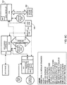
- a building block of the system can comprise a plurality of parallel modular converter modules (“modules”) 100 that can be networked together to form a parallel modular converter (“converter”), discussed below.
- each module 100 can comprise onboard processing.
- the module 100 can comprise at least three processors: the Motor Control Digital Signal Processor ("DSP") 105, the protection processor 110, and the logic processor 115.
- DSP Motor Control Digital Signal Processor
- protection processor 110 may be denoted a protection controller
- logic processor 115 may be denoted logic controller.
- the DSP 105 can generate, for example, a high-frequency gate drive pulse width modulation signal (PWM) 120 to activate the gate driver 125.
- PWM gate drive pulse width modulation signal
- the gate driver 125 acts essentially as the switching side of the power module 100, much like an electrical relay.
- the output 180 of the module 100 is regulated by the PWM signal 120.
- the DSP 105 can utilize signals from various sensors via a signal processor 135 and/or signals via a module communications bus 140, discussed below.
- the DSP 105 can utilize sensors including, for example and not limitation, temperature sensors 150 and shoot-through sensors 155 to detect potentially damaging conditions.
- the DSP 105 can utilize sensors including current sensors (to detect overcurrent conditions), voltage sensors (to detect overvoltage conditions), motor speed and position sensors (to detect over-speed conditions).
- many of these sensors e.g., current, voltage, rotor speed and position sensors
- the signal processor 135 can condition signals from the sensors and can include an Analog to Digital Converter (ADC) 135a.
- the ADC 135 can be a discrete unit that connects via a communications interface to the processors 105, 110, 115.
- the ADC 135 can be integrated into one or more of the processors 105, 110, 115.
- Sensor data can comprise, for example and not limitation, module input and output current and voltage, motor position, DC link DM (differential mode) and CM (common mode), voltage and current, motor speed, and power module temperature.
- the DSP 105 pulse width modulation method and output power level can be configured by the logic processor 115.
- a module communications bus 140 can be utilized.
- load sensor signals and DSP configurations can comprise datasets to be transmitted to a master data logger 310, as discussed below.
- the reference clocks are preferably at least synchronized between parallel modules 100 (i.e., modules 100 that are currently feeding power to the same load). In some embodiments, for very accurate synchronization, methods known in the art such as, for example, synchronization via fiber optic cables can be used. Fiber optic can be advantageous because it is immune to the EMI noise generated by the power module switching.
- the protection processor 110 can enable safe operation of the module 100.
- the protection processor 110 can monitor various sensors for unsafe operating conditions including, but not limited to, output AC current and voltage sensors 145, gate driver and inverter temperatures 150, and shoot-through voltage 155.
- the protection processor 110 can also monitor, for example, motor over-speed, over-voltage (DC link), overcurrent at input or output, over-voltage at input and output, CM (common mode) current, excessive voltage ripple, unbalanced input/output current, open phase, and computer failure protection (e.g., if the DSP fails, the protection processor 110 can disable the gate driver 125 independently).
- the protection processor 110 can also compare actual PWM configuration to the commanded PWM configuration. If these signals do not match, the gate driver 125 can also be disabled.
- the protection processor 110 can be directly connected to the gate driver 125 enabling nearly instantaneous shutdowns of the inverter 160 should a fault be detected.
- Module 100 input fault protection can also be provided by the protection processor 110 in communication with a master protection controller 305 over the module communications bus 140. Should the protection processor 110 detect a fault, for example, the protection processor 110 can instruct the master protection controller 305 to externally disable the module 100. In some embodiments, module 100 faults can also be recorded by the protection processor 110. In some embodiments, the fault can be stored in the memory 110a (e.g., non-volatile memory) of the protection processor 110 and the module 100 can be disabled until it can be repaired or replaced. To aid in debugging, in some embodiments, the protection processor 110 can also log some or all events with the master data logger 310. In this manner, information regarding module faults, communications, master logic commands and other pertinent information can comprise datasets for logging by the master data logger 310.
- the protection processor 110 can also log some or all events with the master data logger 310. In this manner, information regarding module faults, communications, master logic commands and other pertinent information can comprise datasets for logging by the master data logger 310
- the logic processor 115 can regulate the DSP 105 by configuring the modulation method and output power. Coordination between logic processors 115 in parallel modules 100 can enable equal load sharing and clock synchronization. As a result, each logic processor 115 can communicate with the master logic controller 320 for instructions on which load it is assigned to power at present.
- the module 100 can accept a high-voltage DC power (HVDC) that has been rectified by an external rectifier unit.
- HVDC high-voltage DC power
- the input current and voltage can be monitored by current and voltage sensors 165.
- the DC waveforms can be filtered by a DC electromagnetic inference (EMI) filter 170, which can reduce noise on the DC bus and stabilize input current and voltage.
- EMI DC electromagnetic inference
- the inverter module 160 can then generate AC waveforms, which can be filtered by an output AC EMI filter 175, for use by the system loads.
- additional filters and processors can be used to remove switching transients and smooth the output waveform.
- each module 100 can comprise one small input EMI filter 170, for example, and a larger output EMI filter 175 for each load (connecting EMI filters in series improves filter attenuation).
- Current and voltage waveforms can also be monitored by additional sensors after the output AC EMI Filter 175.
- a rectifier 205 can be integrated into the module 200.
- the module 200 can utilize an AC power input, such as a 3-Phase AC power input.
- the rectifier 205 can comprise, for example and not limitation, an active front end (comprising solid state switches) or traditional passive rectifiers (e.g., multi-pulse autotransformer rectifier units, transformer rectifier units, or diode rectifiers).
- This configuration can provide increased reliability because, for example, a rectifier 205 failure affects only one module 200.
- reliability and safety are improved because there is also a decreased circulating current between modules 200 (i.e., as each module 200 can be isolated from other modules 200).
- this approach incurs a slight increase in cost, weight, volume, and complexity of the modules 200 as the result of the additional components 205, 210.
- additional current and voltage sensors 210 can be used after the rectifier 205 to sense fault conditions.
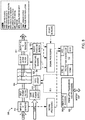
- Figs. 3A-3C depict an overall system 300 architecture for a converter.
- the master controller 302 can comprise, for example and not limitation, a master communications controller 315, a master logic controller 320, a master protection controller 305, a master data logger 310 or master data logging controller, and a power switching network (PSN) 325.
- the master communications controller 315 can connect each module, via each module's 100 module communications bus 140, enabling message exchanges between modules 100.
- messages from the master logic controller 320 can also be routed by the master communications controller 315 to their respective destinations (e.g., to modules 100, external aircraft systems 350, etc.).
- messages processed by the master communications controller 315 can be duplicated and transmitted to the master data logger 310 where they are recorded for concurrent or future analysis.
- the master communications controller 315 can facilitate communications between the modules 100 and external aircraft systems 350 (e.g., aircraft systems 350 external to the system 300 requesting power).
- the master logic controller 320 can receive requests for loads at a specified power level (i.e., current and/or voltage) from external airplane systems. The master logic controller 320 can then allocate modules 100 to fulfill power requests by selecting and configuring the modules 100 and power switching network 325 accordingly.
- the master protection controller 305 can monitor the inputs and outputs to each module 100 including, for example and not limitation, the input current and voltage waveforms of the high-voltage DC Bus and the low-voltage DC Bus. In some embodiments, should a fault occur, the master protection controller 305 can signal the corresponding power switch 330 to disconnect the module 100, record the failure in the master protection controller memory 305a, and send a message of the failure to the master data logger 310. The master protection controller 305 can disable the module 100 until it has been, for example, repaired or replaced.
- Logging of control messages and sensor readings can be handled by the master data logger 310.
- the master data logger 310 can record the data it receives to a data storage medium 335 via a data logging bus 345, which can be in communication via the data storage interface (DSI) 310a.
- DSI data storage interface
- high-speed high-capacity storage devices can be used.
- the reliability of the system 300 can be enhanced using redundant low-voltage DC connections to the master controllers (e.g., the master protection controller 305, master data logger 310, master communications controller 315, and master logic controller 320) and the module's 100 processors (e.g., the motor control DSP 105, protection processor 110, and logic processor 115).
- the master controllers e.g., the master protection controller 305, master data logger 310, master communications controller 315, and master logic controller 320
- the module's 100 processors e.g., the motor control DSP 105, protection processor 110, and logic processor 115.
- the modules 100 can be powered through rectifier units (rectifiers) 340 external to the modules 100.
- Each rectifier 340 can power N (any number of) modules 100.
- N any number of
- the rectifier 340 can be, for example and not limitation, an AFE, passive diode, or multi-pulse autotransformer unit rectifiers.
- the output system 400 can include the power switching network 325.
- the power switching network 325 can switch the array of module 100 outputs (415-1 to 415-N) to their assigned loads through the array of load connections (420-1 to 420-K). Load fault identification and interruption can be provided by the monitoring of current and voltage waveforms by the power switching network protection controller 405. Should the power switching network protection controller 405 detect fault conditions, it can open some or all power switching network 325 switches 410 connected to the load.
- the power switching network protection controller 405 can also record the fault in NVM to aid with either reclosing the switch 410 (i.e., when the fault has been corrected) or permanently disconnecting a switch 410 (e.g., until it is replaced).
- the power switching network protection controller 405 can also inform the power switching network 325 of the fault.
- the power switching network 325 can then open all switches connected to the load, thereby providing redundant system protection.
- the output of the system 300 can include a final stage of EMI attenuation, if required.
- Each load can have one or more dedicated AC Output EMI filters that can filter the combined waveforms from all parallel modules 100.
- the switches 410 can be, for example and not limitation, solid state switches or electromechanical contactors.
- the modules 100 can be primarily controlled by the motor control DSP 105.
- transferring the logic processor 115 functions to the master logic controller 320 can reduce the number of processors required by the module 100. In some embodiments, this can also eliminate, for example, the power distribution negotiation process between each module's logic processor 115.
- the motor control DSP 105 can be configured by the master logic controller 320. Load sensor signals can be transmitted by the master logic controller 320 to the motor control DSP 105, as required.
- system 300 reference clock synchronization to generate synchronous waveforms can still be provided by the motor control DSP 105.
- the protection processor 110 functions can be integrated into the reference clock synchronization to generate synchronous waveforms. In most cases, processing the relatively small number of additional signals does not add significant burden to the motor control DSP 105. Should the motor control DSP 105 identify fault conditions, the motor control DSP 105 can disable the module 100 simply by stopping the PWM signal 120.
- the modules 100 can also comprise a separate data-logging communications bus 505.
- the relatively high-bandwidth data-logging communications can be handled by the data-logging communications bus 505, while the controls communications 510, which are relatively low-bandwidth, high reliability communications, can remain on the module communications bus 140.
- the motor control DSP 105 can be connected to both communications buses 505, 510 enabling both types of communications.
- the system 600 can comprise a more prominent master logic controllers 320 and master data loggers 310, enabling the elimination of the master communications controller 315.
- the master logic controller 320 can connect to every module's logic communications bus to enable configurations to be transmitted to the modules 100. Power distribution between parallel modules 100 and communication with external aircraft systems 605 (i.e., aircraft systems external the system 600, not the aircraft) can be controlled by the master logic controller 320.
- the master data logger 310 can connect to each module's data-logging communications bus 505 enabling higher frequency data logging.
- additional connections can be made to the master protection controller 305 and/or the master logic controller 320 for data storage, while the master protection controller 305 can operate substantially, as discussed above.
- the system 700 can comprise load sensor signal processing that has been relocated from the individual modules 100 to the system 300 output.
- the power switching network protection controller 405 can monitor load signals ensuring no faults occur (e.g., over-temperature or over-speed conditions).
- the power switching network protection controller 405 can relay sensor data including, but not limited to, load temperature 705 and load position 710, to the master logic controller 320 for distribution to the modules 100.
- Fig. 8 depicts an alternative module 800 architecture that eliminates reference synchronization issues (i.e., the synchronization of reference clocks between the modules 100, discussed above). In some embodiments, this can be achieved by relocating the motor controller DSP 105 to the Master Control 302. As mentioned above, the motor controller DSP 105 computes PWM states and then transmits them (e.g., via switch state messages over fiber optics) to the module 800. Fiber optics can be used for intermodule communication, for example, to prevent data corruption on unshielded electrical wires. In this configuration, a fiber optic transceiver 805 can receive the switch state messages.
- a decoder 805a within the fiber optic transceiver 805 can then generate an analog gate drive signal 810 for the gate driver 815.
- the fiber optic transceiver 805 can transmit, receive, encode, and decode signals from electrical domain to optical and vice versa.
- Fiber optics signals can be advantageous because optical signals are immune to the EMI noise generated by the power switching network. Optical media can be useful, therefore, to transmit information over relatively long distances (e.g., between modules 100).
- the decoder 805a can be a logic circuit such as, for example and not limitation, a field programmable gate array (FPGA), complex programmable logic device (CPLD), application specific integrated circuit (ASIC), or processor.
- the protection processor 110 can provide basic protection by monitoring the current and voltage sensors 812,817 for the DC input and the AC output, respectively, the temperature of module devices 820, and inverter shoot-through 825, among other things. Should a fault occur, the protection processor 110 can disable the inverter 830 and inform the master protection controller 305 of the fault.
- the protection processor 110 can communicate with the master protection controller 305 via the fiber optic transceiver 805.
- the protection processor 110 can communicate with the master protection controller 305 via the module communications bus 140.
- switch state messages and protection messages can be transmitted at different frequencies to enable concurrent communication.
- the motor controller DSPs 105 can be relocated from the module 100 to the master controller 302. By consolidating motor controller DSPs 105, clock synchronization is less difficult due to the close proximity of the devices (i.e., most of the time delay element is removed from the synchronization).
- the motor controller DSPs 105 can be placed on a modular accessory board to facilitate repairs of the system 900.
- the number of motor controller DSPs 105 can be equal to the maximum number of simultaneous loads, K, to be controlled by the system 900.
- each motor controller DSP 105 can calculate the PWM state then transmit a switch state message to the modules 100, with parallel modules 100 receiving switch state messages from the same motor controller DSPs 105.
- a PWM router 905 can be used to route the switch state messages to parallel modules 100.
- Sensor signals such as, for example, load currents and voltages, can be routed to the respective motor controller DSPs 105 by a load sensors router 910.
- the master logic controller 320 can communicate directly with each motor controller DSPs 105 to configure the necessary control variables (e.g., pulse width and magnitude).
- fiber optic transceivers 805 can be used to communicate with the modules 100. Multiple wavelengths/frequencies can also be used to enable the concurrent transmission and/or reception of switch state messages and module fault messages.
- the architecture discussed above can provide high reliability because each module's 100 controllers operate nearly independently. In most cases, interaction with other controllers is limited to the allocation of power distribution between the logic processors 115 of various modules 100 and the distribution of load and power by the master logic controller 320. In this configuration, for example, a module 100 failure will not affect the operation of other modules 100.
- communication is simplified as the module communications bus 140 provides an interface between the various module processors (e.g. the DSP 105, the protection processor 110, and the logic processor 115) and the master controllers.
- the various module processors e.g. the DSP 105, the protection processor 110, and the logic processor 115
- this architecture can be somewhat less cost effective and more difficult to implement. Utilization of a dedicated logic controller for minimal tasks, for example, can result in unused processing power increasing module costs. Integration of logic controller functions into other controllers such as the master logic controller 320, on the other hand, would decrease costs and module complexity. Implementation of synchronized reference clocks can add complexity and cost to the module.
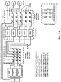
- the system 1000 can control a system of parallel modular inverters 1015 to drive multiple and/or different types of AC or DC machines 1010.
- the system 1000 can comprise a plurality of parallel modular inverters 1015 connected in parallel, each of which is able to be configured to receive any of a plurality control algorithms 1022a, 1022b, 1022c embedded in a control system 1020 via a reconfigurable control switching network 1025.
- Each of the parallel modular inverters 1015 can be configured to drive one or more of the plurality of AC machines 1010 on the load side via a reconfigurable power switching network 1030.
- any of the inverters from the plurality inverters 1015 in parallel is accessible to drive any motor of the plurality motors 1010 (or other electrical loads) on the load side and any control algorithm of a plurality control algorithms 1022 embedded in the system 1000 is accessible to control any of the plurality inverters 1015.
- one or more inverters 1015 can drive one motor 1010, as necessary to meet load requirements, and/or a plurality of motors 1010 on the load side can be driven at the same time, each of which can be driven with one or more inverters 1015.
- a plurality of motors 1010 on the load side can be driven at the same time with the same control algorithm (e.g., 1022a) or a different control algorithm (e.g., 1022b).
- the system can comprise a system controller 1035 configured to communicate with a vehicle controller 1040 to, for example, obtain operation commands from the vehicle controller 1040 and provide system 1000 status signals to the vehicle controller 1040, among other things.
- the system controller 1035 can also reconfigure the power switching network 1030 to provide an appropriate number of inverter modules 1015 in parallel to drive a motor 1010 in real time. In other words, when the load from a motor 1010 is increased, the system controller 1035 can signal the power switching network 1030 to place more inverter modules 1015 in parallel. Conversely, of course, when motor load is decreased, the system controller 1035 can signal the power switching network 1030 to disengage one or more inverter modules 1015. If necessary, the system controller 1035 can then place them in parallel with other inverter modules 1015 to drive other loads 1010.
- the system controller 1035 can also reconfigure the control switching network 1025 to provide appropriate motor control algorithms 1022 to one or more of inverter modules 1015 driving one or more motor types.
- the system controller 1035 can provide algorithms related to, for example and not limitation, field oriented control (FOC), direct torque control (DTC), voltage over frequency Control (V/F). This can be useful, for example, to efficiently drive specific motor types (e.g., induction motors, synchronous motors, permanent magnet synchronous motors, brushless DC motors, etc.).
- FOC field oriented control
- DTC direct torque control
- V/F voltage over frequency Control
- system controller 1035 can also send, for example and not limitation, motor speed, torque, or power reference values to corresponding motors 1010 (or motor controllers).
- system controller 1035 can be stored and run on an embedded controller.
- the system controller 1035 can comprise, for example and not limitation a microcontroller processor, FPGA, or ASIC.
- the system controller 1035 can use a real time simulator/emulator or can be run in real-time.
- the number of motor controller algorithms 1022 can be determined by the number of different motor loads. If the system 1000 has three different types of motors 1010 to drive, for example, then three motor controller algorithms 1022 can be developed, with each motor control algorithm 1022 specific to the motor load. Of course, if all three motors 1010 perform the same function with the same motor, it is possible that all three loads can be powered using the same algorithm 1022.
- the control switching network 1025 can dynamically configure one or more inverters 1015 each of which can be driven by a specific control algorithm 1022, or a common control algorithm 1022, which is routed through control switching network 1025 per commands from the system controller 1035. In some embodiments, time delay between signals into and out of control switching network 1025 can be minimized to improve motor drive performance.
- the control switching network 1025 can be, for example, in a software or hardware implementation.
- a software coded control switching network 1025 can be run on, for example and not limitation, an embedded controller, real-time simulator, or computer.
- the control switching network 1025 can be implemented using a hardware device such as, for example and not limitation, CPLDs, ASICs, or FPGAs.
- the power switching network 1030 can dynamically configure one or more inverters to drive one or more motors per one or more specific control algorithms from the system controller 1035. In some embodiments, the power switching network 1030 can act as a short circuit and/or over current protection device. In this case, the power switches 1030a associated with the short-circuit or over-current load open when a fault is detected.
- the power switching network 1030 can be implemented using, for example and not limitation, solid state relays, mechanical relays, transistors, and other controllable power switches.
- the inverters 1015 convert DC power to the requested AC power (e.g., at different voltage levels, frequencies, waveforms, etc.) to drive various AC machines (e.g., AC motors 1010) per the motor algorithm 1022 and system controller 1035.
- the inverters can comprise, for example and not limitation, insulated-gate bipolar transistors (IGBTs), metal-oxide-semiconductor field-effect transistors (MOSFETs), and bipolar junction transistors (BJTs).
- IGBTs insulated-gate bipolar transistors
- MOSFETs metal-oxide-semiconductor field-effect transistors
- BJTs bipolar junction transistors
- the system 1000 can assign loads based on a load priority factor. In other words, if, for example, the number of loads requested by external aircraft systems 1040 (i.e., external to the system 1000) is larger than can be provided by the module 100, the system 1000 can assign loads by a load priority factor, with higher priority loads being powered before lower priority loads. If the aircraft 1040 makes a request for a large load, such as to lower the landing gear, for example, the system 1000 can temporarily reassign some or all of the modules 1015 to power the landing gear motors. When the landing gear is down and locked, in turn, the system 1000 can reassign the modules 1015 to their previous loads (or to now existing loads). So, for example, the cabin fan can be temporarily deactivated in favor of the landing gear and then restarted when the gear is down.
- a load priority factor if, for example, the number of loads requested by external aircraft systems 1040 (i.e., external to the system 1000) is larger than can be provided by the module 100, the system 1000 can assign loads by
- the system 1000 may power some or all of the loads at a reduced setting. In this manner, all loads are powered, but may operate at a lower speed or capacity. So, for example, the aircraft cabin fans, lighting, and entertainment system may request power at the same time in excess of the system 1000 rating. As a result, the system 1000 can, for example, provide full power to the entertainment system, but slightly reduce cabin fan speeds and lighting intensity to reduce overall power demand.
- embodiments of the present disclosure can also comprise a method 1200 for distributing power.
- the method 1200 can comprise receiving 1205 a load request from the vehicle (e.g., load requests from the vehicle controller 1040).
- the controller can then determine 1210 if the load requested is above or below the power rating for a single module. If the load request is below the rating for a single module, the controller can assign 1220a the load to a single module. If, on the other hand, the load is greater than a single module can power, the controller can parallel 1215 the number of modules ("X") together that are required to power the load and then assign 1220b the load to the X modules. The controller can then activate 1225 the modules providing the necessary load.
- X number of modules
- the vehicle can request 1230 that the load be disconnected and the controller can disconnect 1235 the module, or modules.
- the system can also continuously or periodically check 1240 for current system requirements and reassign modules as required.
- each module 100 can have a 10A rating. With ten modules 100 in a converter 300, therefore, the converter can provide 100A. If the aircraft requests a 25A load to power the hydraulic motors for the landing gear, for example, the system 300 can determine that the load requires at least three modules 100, place three modules 100 in parallel, and then assign and activate three modules 100 to the load. If, during the operation of the landing gear, for example, the power requirements change - e.g., the power required to start the motors is greater than the continuous power to run the motors - the system 300 can remove (or add) modules 100 as the load changes.
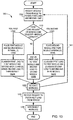
- embodiments of the present disclosure can also comprise a method 1300 for distributing power for multiple loads.
- the method 1300 can comprise receiving 1305 at least two load requests from the vehicle.
- the controller can then determine 1310 if the load requests are above or below the power rating for a single module. If the load requests are below the rating for a single module, the controller can assign 1320b each load to a single module. If, on the other hand, either (or both) load is greater than a single module can power, the controller can parallel 1315a, 1315c two or more modules together and then assign 1320a, 1320c the loads to the parallel modules, as required.
- the system can then activate 1325 the modules.
- the system can also continuously or periodically check 1340 for current system requirements and reassign 1320 modules as required.
- the vehicle can request 1330 that the load be disconnected and the controller can disconnect 1335 the module, or modules for that load.
- each module 100 can again have a 10A rating and ten modules 100 in a converter 300 for a total of 100A capacity. If the aircraft requests a first, 15A, load to power the hydraulic motors for the landing gear, for example, and a second, 7.5A, load to turn the cabin fan on low, the system 300 can determine that the load requires at least three modules 100. The system 300 can place a first module 100 and a second module 100 in parallel. The system 300 can then assign the first load to the first module 100 and the second module 100 and the second load to a third module 100.
- the system 300 can again continuously or intermittently check to see if the vehicle power requirements have changed 1340. If, during the operation of the landing gear, for example, the power requirements change - e.g., the power required to start the motors is greater than the continuous power to run the motors - and/or the vehicle requests that the cabin fan be placed on high, the system 300 can decouple 1315c the first and second modules, pair the second and third modules and assign 1320c the first load (the landing gear) to the first module 100 and the second load (the cabin fan) to the second and third modules 100 as the load changes.
- the power requirements change e.g., the power required to start the motors is greater than the continuous power to run the motors - and/or the vehicle requests that the cabin fan be placed on high
- the system 300 can decouple 1315c the first and second modules, pair the second and third modules and assign 1320c the first load (the landing gear) to the first module 100 and the second load (the cabin fan) to the second and third modules 100 as the load changes
- embodiments of the present disclosure are not so limited.
- other suitable configurations and components could be selected without departing from the disclosure.
- location and configuration used for various features of embodiments of the present disclosure such as, for example, the number of modules, the types of electronics used, etc. can be varied according to a particular aircraft or application that requires a slight variation due to, for example, the size or construction of the aircraft, or weight or power constraints. Such changes are intended to be embraced within the scope of this disclosure.
Landscapes
- Engineering & Computer Science (AREA)
- Power Engineering (AREA)
- Physics & Mathematics (AREA)
- General Physics & Mathematics (AREA)
- Automation & Control Theory (AREA)
- Inverter Devices (AREA)
- Dc-Dc Converters (AREA)
- Supply And Distribution Of Alternating Current (AREA)
Claims (13)
- Convertisseur à modules parallèles (300) comprenant :un premier module de convertisseur à modules parallèles (100, 200) destiné à fournir un premier signal de sortie de courant alternatif (CA) et relié à un bus de communications entre modules (140) ;un deuxième module de convertisseur à modules parallèles (100, 200) destiné à fournir un deuxième signal de sortie de CA et relié au bus de communications entre modules (140) ;un boîtier électronique de commande maître (320) destiné à attribuer une première charge (420) au premier module de convertisseur à modules parallèles (415-1) et/ou au deuxième module de convertisseur à modules parallèles (415-2) ;le bus de communications entre modules (140) reliant le premier module de convertisseur à modules parallèles et le deuxième module de convertisseur à modules parallèles ; etun organe de commande des communications maître (315) relié au bus de communications entre modules et au boîtier électronique de commande maître pour acheminer des messages entre eux ;le convertisseur à modules parallèles étant caractérisé en ce qu'il comprend :un enregistreur de données de référence (310) destiné à enregistrer un ou plusieurs ensembles de données ;un support de stockage de données (335) destiné à stocker le ou les ensembles de données ; etun bus d'enregistrement de données (345) reliant l'enregistreur de données de référence et le support de stockage de données ; et caractérisé par le fait queles premier et deuxième modules parallèles (100) du convertisseur comprennent en outre un bus de communications d'enregistrement de données (505) séparé en liaison avec l'enregistreur de données de référence (310) ;des communications d'enregistrement de données étant communiquées par l'intermédiaire du bus de communications d'enregistrement de données (505) séparé et du bus d'enregistrement de données (345), etdes communications de commande étant communiquées par l'intermédiaire du bus de communications entre modules (140).
- Convertisseur à modules parallèles selon la revendication 1, dans lequel le ou les ensembles de données comprennent des commandes issues du boîtier électronique de commande maître, des messages issus de l'organe de commande des communications maître, des messages de défaillance et/ou des relevés issus de capteurs.
- Convertisseur à modules parallèles selon la revendication 1 ou 2, dans lequel le boîtier électronique de commande maître est agencé pour attribuer la première charge au premier module de convertisseur à modules parallèles et une deuxième charge au deuxième module de convertisseur à modules parallèles.
- Convertisseur à modules parallèles selon l'une quelconque des revendications précédentes, dans lequel le boîtier électronique de commande maître est agencé pour mettre en parallèle le premier module de convertisseur à modules parallèles et le deuxième module de convertisseur à modules parallèles, au moyen d'un réseau de commutation de puissance et pour attribuer la première charge au premier module de convertisseur à modules parallèles et au deuxième module de convertisseur à modules parallèles.
- Convertisseur à modules parallèles selon l'une quelconque des revendications précédentes, comprenant en outre :un troisième module de convertisseur à modules parallèles (415-3) destiné à fournir un troisième signal de sortie de CA et relié au bus de communications entre modules,ledit boîtier électronique de commande maître étant agencé pour mettre en parallèle le premier module de convertisseur à modules parallèles, le deuxième module de convertisseur à modules parallèles et le troisième module de convertisseur à modules parallèles, au moyen d'un réseau de commutation de puissance et pour attribuer la première charge au premier module de convertisseur à modules parallèles, au deuxième module de convertisseur à modules parallèles et au troisième module de convertisseur à modules parallèles.
- Convertisseur à modules parallèles selon l'une quelconque des revendications précédentes, comprenant en outre :un organe de commande de protection maître (305) destiné à surveiller une ou plusieurs entrées et sorties de premier module de convertisseur à modules parallèles, et une ou plusieurs entrées et sorties de deuxième module de convertisseur à modules parallèles,ledit organe de commande de protection étant agencé pour désactiver le premier module de convertisseur à modules parallèles ou le deuxième module de convertisseur à modules parallèles, ou bien à la fois le premier module de convertisseur à modules parallèles et le deuxième module de convertisseur à modules parallèles, lorsqu'une panne est détectée.
- Convertisseur à modules parallèles selon la revendication 6, dans lequel la ou les entrées de premier module de convertisseur à modules parallèles et la ou les entrées de deuxième module de convertisseur à modules parallèles comprennent une tension d'entrée et/ou une intensité d'entrée.
- Convertisseur à modules parallèles selon la revendication 6 ou 7, dans lequel la ou les sorties de premier module de convertisseur à modules parallèles et la ou les sorties de deuxième module de convertisseur à modules parallèles comprennent une tension de sortie et/ou une intensité de sortie.
- Procédé d'alimentation comprenant les opérations consistant à :relier un premier module de convertisseur à modules parallèles (415-1) et un deuxième module de convertisseur à modules parallèles (415-2), ainsi qu'un boîtier électronique de commande maître (320) à l'aide d'un bus de communications entre modules (140) de convertisseur à modules parallèles ;acheminer des communications entre le premier module de convertisseur à modules parallèles, le deuxième module de convertisseur à modules parallèles et le boîtier électronique de commande maître, à l'aide d'un organe de commande des communications maître ;recevoir (1205) une ou plusieurs demandes de charge en provenance d'un ou plusieurssystèmes d'aéronef, au niveau du boîtier électronique de commande maître ; etattribuer (1220A, 1220B) la ou les demandes de charge au premier module de convertisseur à modules parallèles, au deuxième module de convertisseur à modules parallèles ou aux deux, à l'aide du boîtier électronique de commande maître,ledit premier module de convertisseur à modules parallèles fournissant un premier signal de courant alternatif (CA) et le deuxième module de convertisseur à modules parallèles fournissant un deuxième signal de CA ;le procédé étant caractérisé en ce qu'il comprend les opérations consistant à :enregistrer un ou plusieurs ensembles de données à l'aide d'un enregistreur de données de référence (310) ;stocker le ou les ensembles de données dans un support de stockage de données (335) relié à l'enregistreur de données de référence (310) par l'intermédiaire d'un bus d'enregistrement de données (345) ;doter les modules d'un bus de communications d'enregistrement de données (505) séparé en liaison avec l'enregistreur de données de référence (310) ;communiquer des communications d'enregistrement de données par l'intermédiaire du bus de communications d'enregistrement de données (505) séparé et du bus d'enregistrement de données (345) ; etcommuniquer des communications de commande par l'intermédiaire du bus de communications entre modules (140).
- Procédé selon la revendication 9, comprenant en outre les opérations consistant à :recevoir une demande de première charge en provenance d'un premier système d'aéronef, au niveau du boîtier électronique de commande maître,mettre en parallèle (1215) le premier module de convertisseur à modules parallèles et le deuxième module de convertisseur à modules parallèles, à l'aide d'un réseau de commutation de puissance (325), etattribuer la demande de première charge au premier module de convertisseur à modules parallèles et au deuxième module de convertisseur à modules parallèles.
- Procédé selon la revendication 9, comprenant en outre les opérations consistant à :recevoir une demande de première charge au niveau du boîtier électronique de commande maître en provenance d'un premier système d'aéronef,mettre en parallèle le premier module de convertisseur à modules parallèles, le deuxième module de convertisseur à modules parallèles et un troisième module de convertisseur à modules parallèles (415-3), à l'aide d'un réseau de commutation de puissance, etattribuer la demande de première charge au premier module de convertisseur à modules parallèles, au deuxième module de convertisseur à modules parallèles et au troisième module de convertisseur à modules parallèles ;ledit troisième module de convertisseur à modules parallèles fournissant un troisième signal de sortie de CA.
- Procédé selon la revendication 9, comprenant en outre les opérations consistant à :recevoir une demande de première charge en provenance du ou des systèmes d'aéronef, au niveau du boîtier électronique de commande maître ;mettre en parallèle le premier module de convertisseur à modules parallèles et le deuxième module de convertisseur à modules parallèles, à l'aide d'un réseau de commutation de puissance ;attribuer la demande de première charge au premier module de convertisseur à modules parallèles et au deuxième module de convertisseur à modules parallèles, à l'aide du boîtier électronique de commande maître ;détecter une panne dans le premier module de convertisseur à modules parallèles, à l'aide d'un organe de commande de protection maître (305) ;mettre en parallèle le deuxième module de convertisseur à modules parallèles et un troisième module de convertisseur à modules parallèles, à l'aide du réseau de commutation de puissance ;attribuer la demande de première charge au deuxième module de convertisseur à modules parallèles et au troisième module de convertisseur à modules parallèles, à l'aide du boîtier électronique de commande maître ; etdésactiver le premier module de convertisseur à modules parallèles à l'aide de l'organe de commande de protection maître.
- Procédé selon la revendication 9, comprenant en outre les opérations consistant à :recevoir une demande de première charge et une demande de deuxième charge en provenance du ou des systèmes d'aéronef, au niveau du boîtier électronique de commande maître ; etattribuer la demande de première charge au premier module de convertisseur à modules parallèles et la demande de deuxième charge au deuxième module de convertisseur à modules parallèles, à l'aide du boîtier électronique de commande maître.
Applications Claiming Priority (1)
| Application Number | Priority Date | Filing Date | Title |
|---|---|---|---|
| US14/502,350 US10079493B2 (en) | 2014-09-30 | 2014-09-30 | Parallel modular converter architecture |
Publications (3)
| Publication Number | Publication Date |
|---|---|
| EP3012704A2 EP3012704A2 (fr) | 2016-04-27 |
| EP3012704A3 EP3012704A3 (fr) | 2016-07-27 |
| EP3012704B1 true EP3012704B1 (fr) | 2022-01-05 |
Family
ID=54252032
Family Applications (1)
| Application Number | Title | Priority Date | Filing Date |
|---|---|---|---|
| EP15187281.9A Active EP3012704B1 (fr) | 2014-09-30 | 2015-09-29 | Architecture modulaire de convertisseur parallèle |
Country Status (7)
| Country | Link |
|---|---|
| US (2) | US10079493B2 (fr) |
| EP (1) | EP3012704B1 (fr) |
| JP (1) | JP6626657B2 (fr) |
| CN (1) | CN105471310B (fr) |
| BR (1) | BR102015024964B1 (fr) |
| CA (2) | CA3020117C (fr) |
| RU (1) | RU2701157C2 (fr) |
Families Citing this family (26)
| Publication number | Priority date | Publication date | Assignee | Title |
|---|---|---|---|---|
| US9647455B2 (en) * | 2014-09-30 | 2017-05-09 | The Boeing Company | EMI filter systems and methods for parallel modular converters |
| FR3038274B1 (fr) * | 2015-07-01 | 2020-10-23 | Airbus Operations Sas | Systeme de raccordement electrique d'un equipement de cabine d'un avion a un systeme de controle et a au moins une source d'alimentation electrique dudit avion |
| US10020759B2 (en) | 2015-08-04 | 2018-07-10 | The Boeing Company | Parallel modular converter architecture for efficient ground electric vehicles |
| US9991778B2 (en) | 2016-02-29 | 2018-06-05 | The Boeing Company | Balancing current within a modular converter system |
| US10656026B2 (en) | 2016-04-15 | 2020-05-19 | Emerson Climate Technologies, Inc. | Temperature sensing circuit for transmitting data across isolation barrier |
| US10305373B2 (en) | 2016-04-15 | 2019-05-28 | Emerson Climate Technologies, Inc. | Input reference signal generation systems and methods |
| US10277115B2 (en) | 2016-04-15 | 2019-04-30 | Emerson Climate Technologies, Inc. | Filtering systems and methods for voltage control |
| US9933842B2 (en) | 2016-04-15 | 2018-04-03 | Emerson Climate Technologies, Inc. | Microcontroller architecture for power factor correction converter |
| US10763740B2 (en) | 2016-04-15 | 2020-09-01 | Emerson Climate Technologies, Inc. | Switch off time control systems and methods |
| US10320322B2 (en) | 2016-04-15 | 2019-06-11 | Emerson Climate Technologies, Inc. | Switch actuation measurement circuit for voltage converter |
| US10770966B2 (en) | 2016-04-15 | 2020-09-08 | Emerson Climate Technologies, Inc. | Power factor correction circuit and method including dual bridge rectifiers |
| US10454393B2 (en) | 2016-07-25 | 2019-10-22 | The Boeing Company | Balancing current within a parallel modular converter system |
| US10102085B2 (en) * | 2016-08-25 | 2018-10-16 | GM Global Technology Operations LLC | Coordinated multi-mode allocation and runtime switching for systems with dynamic fault-tolerance requirements |
| US10396554B2 (en) * | 2017-02-13 | 2019-08-27 | The Boeing Company | Power distribution control within a modular converter system using efficiency calculations |
| US9914548B1 (en) * | 2017-02-22 | 2018-03-13 | Imagik International Corporation | USB power management and load distribution system |
| US10587146B2 (en) | 2017-11-21 | 2020-03-10 | Hamilton Sundstrand Corporation | Power dissipation monitoring and load management |
| KR102224292B1 (ko) * | 2019-12-02 | 2021-03-09 | 계양전기 주식회사 | 전동공구의 모터구동 제어회로 |
| CN111525842A (zh) * | 2020-04-16 | 2020-08-11 | 中国航空工业集团公司西安飞机设计研究所 | 一种机载电机驱动控制系统 |
| GB2604364B (en) | 2021-03-03 | 2024-04-17 | Rolls Royce Plc | Electrical power systems |
| GB2604365B (en) * | 2021-03-03 | 2024-05-22 | Rolls Royce Plc | Electrical power systems |
| GB2604366B (en) | 2021-03-03 | 2023-10-25 | Rolls Royce Plc | Electrical power systems |
| CN113098261A (zh) * | 2021-04-06 | 2021-07-09 | 佛山仙湖实验室 | 一种混合动力汽车可调式大功率dc/dc变换器的控制方法 |
| CN113541187B (zh) * | 2021-07-13 | 2022-09-02 | 湖南普莱思迈电子科技有限公司 | 中频正弦波交流电源并机系统及其控制系统 |
| CN113904433A (zh) * | 2021-09-29 | 2022-01-07 | 深圳威迈斯新能源股份有限公司 | 一种能实现冗余的电动汽车供电系统及其控制方法 |
| CN114407734B (zh) * | 2021-12-21 | 2022-08-23 | 西南交通大学 | 一种柔性牵引供电系统及保护方法 |
| CN114721494B (zh) * | 2022-06-07 | 2022-09-02 | 深圳市明珞锋科技有限责任公司 | 一种电源输出电数字数据处理方法 |
Family Cites Families (25)
| Publication number | Priority date | Publication date | Assignee | Title |
|---|---|---|---|---|
| JP2834201B2 (ja) * | 1989-08-11 | 1998-12-09 | 株式会社日立製作所 | 電力供給システム |
| EP0409226A3 (en) | 1989-07-21 | 1993-01-13 | Hitachi, Ltd. | Power supply control system |
| JPH04312357A (ja) * | 1991-04-12 | 1992-11-04 | Toshiba Corp | 交流電源装置 |
| US5486747A (en) * | 1993-07-29 | 1996-01-23 | United Technologies Motor Systems | General purpose motor controller |
| US6768279B1 (en) | 1994-05-27 | 2004-07-27 | Emerson Electric Co. | Reprogrammable motor drive and control therefore |
| US6792337B2 (en) * | 1994-12-30 | 2004-09-14 | Power Measurement Ltd. | Method and system for master slave protocol communication in an intelligent electronic device |
| CN100394667C (zh) * | 2003-07-30 | 2008-06-11 | 飞瑞股份有限公司 | 不间断电源模块并联控制方法及其系统 |
| US7356336B2 (en) * | 2004-01-06 | 2008-04-08 | The Boeing Company | Systems and methods of recording events onboard a vehicle |
| FR2900635B1 (fr) * | 2006-05-05 | 2008-07-25 | Hispano Suiza Sa | Systeme d'alimentation et de commande d'equipements electriques d'un moteur d'aeronef ou de son environnement |
| US20070295545A1 (en) | 2006-05-11 | 2007-12-27 | Romig Bernard E | Differential Steering and Traction Control For Electrically Propelled Mower |
| US7365511B2 (en) * | 2006-09-12 | 2008-04-29 | Hamilton Sundstrand Corporation | Methods to control high speed electric machines having a front-end EMI filter attached |
| FR2907760B1 (fr) * | 2006-10-25 | 2009-06-12 | Airbus France Sas | Systeme et procede d'alimentation en puissance a bord d'un aeronef. |
| US7615892B2 (en) * | 2006-11-09 | 2009-11-10 | Honeywell International Inc. | Modular and scalable power conversion system for aircraft |
| US7869385B2 (en) * | 2007-10-31 | 2011-01-11 | The Boeing Company | Interactivity with a bus interface card |
| US8062081B2 (en) * | 2007-12-12 | 2011-11-22 | Foss Maritime Company, Inc. | Hybrid propulsion systems |
| US8125164B2 (en) * | 2008-07-18 | 2012-02-28 | The Boeing Company | Parallel motor controller architecture |
| CN101474714A (zh) * | 2008-12-02 | 2009-07-08 | 上海沪工电焊机制造有限公司 | 精密逆变电阻点焊电源dsp控制方法 |
| FR2941107B1 (fr) * | 2009-01-09 | 2015-08-14 | Hispano Suiza Sa | Systeme electrique de demarrage des moteurs d'un aeronef |
| US8400791B2 (en) * | 2010-07-16 | 2013-03-19 | Rockwell Automation Technologies, Inc. | Power layer generation of inverter gate drive signals |
| US9577424B2 (en) * | 2010-07-16 | 2017-02-21 | Rockwell Automation Technologies, Inc. | Parallel motor drive disable verification system and method |
| US20130343105A1 (en) * | 2011-03-16 | 2013-12-26 | Toyota Jidosha Kabushiki Kaisha | Inverter overheating protection control apparatus and inverter overheating protection control method |
| KR101276582B1 (ko) * | 2011-12-27 | 2013-06-19 | 전자부품연구원 | 전원 공급 회로를 가지는 인버터 장치 |
| WO2014025734A2 (fr) | 2012-08-09 | 2014-02-13 | Danfoss Power Electronics A/S | Commande d'onduleur modulaire |
| US9479084B2 (en) * | 2013-02-20 | 2016-10-25 | Infineon Technologies Ag | Pseudo zero vectors for space vector modulation and enhanced space vector modulation |
| JP3184828U (ja) * | 2013-05-08 | 2013-07-18 | 株式会社ティ・アイ・エス | 太陽光発電設備の監視装置 |
-
2014
- 2014-09-30 US US14/502,350 patent/US10079493B2/en active Active
-
2015
- 2015-08-03 RU RU2015132215A patent/RU2701157C2/ru active
- 2015-08-06 JP JP2015155861A patent/JP6626657B2/ja active Active
- 2015-08-14 CA CA3020117A patent/CA3020117C/fr active Active
- 2015-08-14 CA CA2900640A patent/CA2900640C/fr active Active
- 2015-09-29 BR BR102015024964-0A patent/BR102015024964B1/pt active IP Right Grant
- 2015-09-29 EP EP15187281.9A patent/EP3012704B1/fr active Active
- 2015-09-30 CN CN201510641594.9A patent/CN105471310B/zh active Active
-
2017
- 2017-02-01 US US15/421,609 patent/US11431176B2/en active Active
Also Published As
| Publication number | Publication date |
|---|---|
| BR102015024964A2 (pt) | 2016-05-24 |
| CA3020117A1 (fr) | 2016-03-30 |
| CN105471310B (zh) | 2019-12-31 |
| CA3020117C (fr) | 2022-11-08 |
| US20160094039A1 (en) | 2016-03-31 |
| CA2900640A1 (fr) | 2016-03-30 |
| RU2701157C2 (ru) | 2019-09-25 |
| JP2016073190A (ja) | 2016-05-09 |
| EP3012704A3 (fr) | 2016-07-27 |
| CN105471310A (zh) | 2016-04-06 |
| RU2015132215A (ru) | 2017-02-08 |
| US11431176B2 (en) | 2022-08-30 |
| CA2900640C (fr) | 2018-11-20 |
| JP6626657B2 (ja) | 2019-12-25 |
| RU2015132215A3 (fr) | 2019-03-07 |
| BR102015024964B1 (pt) | 2022-03-29 |
| EP3012704A2 (fr) | 2016-04-27 |
| US20170141717A1 (en) | 2017-05-18 |
| US10079493B2 (en) | 2018-09-18 |
Similar Documents
| Publication | Publication Date | Title |
|---|---|---|
| EP3012704B1 (fr) | Architecture modulaire de convertisseur parallèle | |
| US9991719B2 (en) | Systems and methods for reducing circulating current and phase to phase imbalance in a parallel modular converter system | |
| US9647455B2 (en) | EMI filter systems and methods for parallel modular converters | |
| JP5396670B2 (ja) | 電気的ネットワークの管理方法 | |
| EP2442425B1 (fr) | Système de commande de la puissance électrique pour un véhicule | |
| CA2890083C (fr) | Dispositif de distribution d'alimentation pour prises ca faible frequence | |
| CN104067472A (zh) | 具有多个输入端的安全稳压连续电源系统 | |
| CN107769188B (zh) | 开关电源并机系统 | |
| EP3036129B1 (fr) | Alimentation pour matériel ferroviaire critique | |
| CA2892211C (fr) | Systeme mutateur et installation eolienne ou hydroelectrique | |
| CA2905116C (fr) | Systemes et methodes de reduction du courant baladeur et du desequilibre phase-phase dans un systeme de convertisseur modulaire parallele |
Legal Events
| Date | Code | Title | Description |
|---|---|---|---|
| PUAI | Public reference made under article 153(3) epc to a published international application that has entered the european phase |
Free format text: ORIGINAL CODE: 0009012 |
|
| 17P | Request for examination filed |
Effective date: 20150929 |
|
| AK | Designated contracting states |
Kind code of ref document: A2 Designated state(s): AL AT BE BG CH CY CZ DE DK EE ES FI FR GB GR HR HU IE IS IT LI LT LU LV MC MK MT NL NO PL PT RO RS SE SI SK SM TR |
|
| AX | Request for extension of the european patent |
Extension state: BA ME |
|
| PUAL | Search report despatched |
Free format text: ORIGINAL CODE: 0009013 |
|
| AK | Designated contracting states |
Kind code of ref document: A3 Designated state(s): AL AT BE BG CH CY CZ DE DK EE ES FI FR GB GR HR HU IE IS IT LI LT LU LV MC MK MT NL NO PL PT RO RS SE SI SK SM TR |
|
| AX | Request for extension of the european patent |
Extension state: BA ME |
|
| RIC1 | Information provided on ipc code assigned before grant |
Ipc: H02M 7/493 20070101ALN20160622BHEP Ipc: G05B 23/02 20060101AFI20160622BHEP |
|
| STAA | Information on the status of an ep patent application or granted ep patent |
Free format text: STATUS: EXAMINATION IS IN PROGRESS |
|
| 17Q | First examination report despatched |
Effective date: 20180209 |
|
| STAA | Information on the status of an ep patent application or granted ep patent |
Free format text: STATUS: EXAMINATION IS IN PROGRESS |
|
| GRAP | Despatch of communication of intention to grant a patent |
Free format text: ORIGINAL CODE: EPIDOSNIGR1 |
|
| STAA | Information on the status of an ep patent application or granted ep patent |
Free format text: STATUS: GRANT OF PATENT IS INTENDED |
|
| RIC1 | Information provided on ipc code assigned before grant |
Ipc: G05B 23/02 20060101AFI20210317BHEP Ipc: H02M 7/493 20070101ALN20210317BHEP Ipc: H02M 1/32 20070101ALN20210317BHEP Ipc: H02J 4/00 20060101ALN20210317BHEP Ipc: H02M 1/00 20060101ALN20210317BHEP |
|
| INTG | Intention to grant announced |
Effective date: 20210412 |
|
| GRAS | Grant fee paid |
Free format text: ORIGINAL CODE: EPIDOSNIGR3 |
|
| GRAA | (expected) grant |
Free format text: ORIGINAL CODE: 0009210 |
|
| STAA | Information on the status of an ep patent application or granted ep patent |
Free format text: STATUS: THE PATENT HAS BEEN GRANTED |
|
| AK | Designated contracting states |
Kind code of ref document: B1 Designated state(s): AL AT BE BG CH CY CZ DE DK EE ES FI FR GB GR HR HU IE IS IT LI LT LU LV MC MK MT NL NO PL PT RO RS SE SI SK SM TR |
|
| REG | Reference to a national code |
Ref country code: GB Ref legal event code: FG4D |
|
| REG | Reference to a national code |
Ref country code: CH Ref legal event code: EP |
|
| REG | Reference to a national code |
Ref country code: AT Ref legal event code: REF Ref document number: 1461139 Country of ref document: AT Kind code of ref document: T Effective date: 20220115 |
|
| REG | Reference to a national code |
Ref country code: DE Ref legal event code: R096 Ref document number: 602015076198 Country of ref document: DE |
|
| REG | Reference to a national code |
Ref country code: IE Ref legal event code: FG4D |
|
| REG | Reference to a national code |
Ref country code: LT Ref legal event code: MG9D |
|
| REG | Reference to a national code |
Ref country code: NL Ref legal event code: MP Effective date: 20220105 |
|
| REG | Reference to a national code |
Ref country code: AT Ref legal event code: MK05 Ref document number: 1461139 Country of ref document: AT Kind code of ref document: T Effective date: 20220105 |
|
| PG25 | Lapsed in a contracting state [announced via postgrant information from national office to epo] |
Ref country code: NL Free format text: LAPSE BECAUSE OF FAILURE TO SUBMIT A TRANSLATION OF THE DESCRIPTION OR TO PAY THE FEE WITHIN THE PRESCRIBED TIME-LIMIT Effective date: 20220105 |
|
| PG25 | Lapsed in a contracting state [announced via postgrant information from national office to epo] |
Ref country code: SE Free format text: LAPSE BECAUSE OF FAILURE TO SUBMIT A TRANSLATION OF THE DESCRIPTION OR TO PAY THE FEE WITHIN THE PRESCRIBED TIME-LIMIT Effective date: 20220105 Ref country code: RS Free format text: LAPSE BECAUSE OF FAILURE TO SUBMIT A TRANSLATION OF THE DESCRIPTION OR TO PAY THE FEE WITHIN THE PRESCRIBED TIME-LIMIT Effective date: 20220105 Ref country code: PT Free format text: LAPSE BECAUSE OF FAILURE TO SUBMIT A TRANSLATION OF THE DESCRIPTION OR TO PAY THE FEE WITHIN THE PRESCRIBED TIME-LIMIT Effective date: 20220505 Ref country code: NO Free format text: LAPSE BECAUSE OF FAILURE TO SUBMIT A TRANSLATION OF THE DESCRIPTION OR TO PAY THE FEE WITHIN THE PRESCRIBED TIME-LIMIT Effective date: 20220405 Ref country code: LT Free format text: LAPSE BECAUSE OF FAILURE TO SUBMIT A TRANSLATION OF THE DESCRIPTION OR TO PAY THE FEE WITHIN THE PRESCRIBED TIME-LIMIT Effective date: 20220105 Ref country code: HR Free format text: LAPSE BECAUSE OF FAILURE TO SUBMIT A TRANSLATION OF THE DESCRIPTION OR TO PAY THE FEE WITHIN THE PRESCRIBED TIME-LIMIT Effective date: 20220105 Ref country code: ES Free format text: LAPSE BECAUSE OF FAILURE TO SUBMIT A TRANSLATION OF THE DESCRIPTION OR TO PAY THE FEE WITHIN THE PRESCRIBED TIME-LIMIT Effective date: 20220105 Ref country code: BG Free format text: LAPSE BECAUSE OF FAILURE TO SUBMIT A TRANSLATION OF THE DESCRIPTION OR TO PAY THE FEE WITHIN THE PRESCRIBED TIME-LIMIT Effective date: 20220405 |
|
| PG25 | Lapsed in a contracting state [announced via postgrant information from national office to epo] |
Ref country code: PL Free format text: LAPSE BECAUSE OF FAILURE TO SUBMIT A TRANSLATION OF THE DESCRIPTION OR TO PAY THE FEE WITHIN THE PRESCRIBED TIME-LIMIT Effective date: 20220105 Ref country code: LV Free format text: LAPSE BECAUSE OF FAILURE TO SUBMIT A TRANSLATION OF THE DESCRIPTION OR TO PAY THE FEE WITHIN THE PRESCRIBED TIME-LIMIT Effective date: 20220105 Ref country code: GR Free format text: LAPSE BECAUSE OF FAILURE TO SUBMIT A TRANSLATION OF THE DESCRIPTION OR TO PAY THE FEE WITHIN THE PRESCRIBED TIME-LIMIT Effective date: 20220406 Ref country code: FI Free format text: LAPSE BECAUSE OF FAILURE TO SUBMIT A TRANSLATION OF THE DESCRIPTION OR TO PAY THE FEE WITHIN THE PRESCRIBED TIME-LIMIT Effective date: 20220105 Ref country code: AT Free format text: LAPSE BECAUSE OF FAILURE TO SUBMIT A TRANSLATION OF THE DESCRIPTION OR TO PAY THE FEE WITHIN THE PRESCRIBED TIME-LIMIT Effective date: 20220105 |
|
| PG25 | Lapsed in a contracting state [announced via postgrant information from national office to epo] |
Ref country code: IS Free format text: LAPSE BECAUSE OF FAILURE TO SUBMIT A TRANSLATION OF THE DESCRIPTION OR TO PAY THE FEE WITHIN THE PRESCRIBED TIME-LIMIT Effective date: 20220505 |
|
| REG | Reference to a national code |
Ref country code: DE Ref legal event code: R097 Ref document number: 602015076198 Country of ref document: DE |
|
| PG25 | Lapsed in a contracting state [announced via postgrant information from national office to epo] |
Ref country code: SM Free format text: LAPSE BECAUSE OF FAILURE TO SUBMIT A TRANSLATION OF THE DESCRIPTION OR TO PAY THE FEE WITHIN THE PRESCRIBED TIME-LIMIT Effective date: 20220105 Ref country code: SK Free format text: LAPSE BECAUSE OF FAILURE TO SUBMIT A TRANSLATION OF THE DESCRIPTION OR TO PAY THE FEE WITHIN THE PRESCRIBED TIME-LIMIT Effective date: 20220105 Ref country code: RO Free format text: LAPSE BECAUSE OF FAILURE TO SUBMIT A TRANSLATION OF THE DESCRIPTION OR TO PAY THE FEE WITHIN THE PRESCRIBED TIME-LIMIT Effective date: 20220105 Ref country code: EE Free format text: LAPSE BECAUSE OF FAILURE TO SUBMIT A TRANSLATION OF THE DESCRIPTION OR TO PAY THE FEE WITHIN THE PRESCRIBED TIME-LIMIT Effective date: 20220105 Ref country code: DK Free format text: LAPSE BECAUSE OF FAILURE TO SUBMIT A TRANSLATION OF THE DESCRIPTION OR TO PAY THE FEE WITHIN THE PRESCRIBED TIME-LIMIT Effective date: 20220105 Ref country code: CZ Free format text: LAPSE BECAUSE OF FAILURE TO SUBMIT A TRANSLATION OF THE DESCRIPTION OR TO PAY THE FEE WITHIN THE PRESCRIBED TIME-LIMIT Effective date: 20220105 |
|
| PLBE | No opposition filed within time limit |
Free format text: ORIGINAL CODE: 0009261 |
|
| STAA | Information on the status of an ep patent application or granted ep patent |
Free format text: STATUS: NO OPPOSITION FILED WITHIN TIME LIMIT |
|
| PG25 | Lapsed in a contracting state [announced via postgrant information from national office to epo] |
Ref country code: AL Free format text: LAPSE BECAUSE OF FAILURE TO SUBMIT A TRANSLATION OF THE DESCRIPTION OR TO PAY THE FEE WITHIN THE PRESCRIBED TIME-LIMIT Effective date: 20220105 |
|
| 26N | No opposition filed |
Effective date: 20221006 |
|
| PG25 | Lapsed in a contracting state [announced via postgrant information from national office to epo] |
Ref country code: SI Free format text: LAPSE BECAUSE OF FAILURE TO SUBMIT A TRANSLATION OF THE DESCRIPTION OR TO PAY THE FEE WITHIN THE PRESCRIBED TIME-LIMIT Effective date: 20220105 |
|
| PG25 | Lapsed in a contracting state [announced via postgrant information from national office to epo] |
Ref country code: MC Free format text: LAPSE BECAUSE OF FAILURE TO SUBMIT A TRANSLATION OF THE DESCRIPTION OR TO PAY THE FEE WITHIN THE PRESCRIBED TIME-LIMIT Effective date: 20220105 |
|
| REG | Reference to a national code |
Ref country code: CH Ref legal event code: PL |
|
| REG | Reference to a national code |
Ref country code: BE Ref legal event code: MM Effective date: 20220930 |
|
| P01 | Opt-out of the competence of the unified patent court (upc) registered |
Effective date: 20230516 |
|
| PG25 | Lapsed in a contracting state [announced via postgrant information from national office to epo] |
Ref country code: LU Free format text: LAPSE BECAUSE OF NON-PAYMENT OF DUE FEES Effective date: 20220929 |
|
| PG25 | Lapsed in a contracting state [announced via postgrant information from national office to epo] |
Ref country code: LI Free format text: LAPSE BECAUSE OF NON-PAYMENT OF DUE FEES Effective date: 20220930 Ref country code: IT Free format text: LAPSE BECAUSE OF FAILURE TO SUBMIT A TRANSLATION OF THE DESCRIPTION OR TO PAY THE FEE WITHIN THE PRESCRIBED TIME-LIMIT Effective date: 20220105 Ref country code: IE Free format text: LAPSE BECAUSE OF NON-PAYMENT OF DUE FEES Effective date: 20220929 Ref country code: CH Free format text: LAPSE BECAUSE OF NON-PAYMENT OF DUE FEES Effective date: 20220930 |
|
| PG25 | Lapsed in a contracting state [announced via postgrant information from national office to epo] |
Ref country code: BE Free format text: LAPSE BECAUSE OF NON-PAYMENT OF DUE FEES Effective date: 20220930 |
|
| PGFP | Annual fee paid to national office [announced via postgrant information from national office to epo] |
Ref country code: GB Payment date: 20230927 Year of fee payment: 9 |
|
| PGFP | Annual fee paid to national office [announced via postgrant information from national office to epo] |
Ref country code: FR Payment date: 20230925 Year of fee payment: 9 Ref country code: DE Payment date: 20230927 Year of fee payment: 9 |
|
| PG25 | Lapsed in a contracting state [announced via postgrant information from national office to epo] |
Ref country code: HU Free format text: LAPSE BECAUSE OF FAILURE TO SUBMIT A TRANSLATION OF THE DESCRIPTION OR TO PAY THE FEE WITHIN THE PRESCRIBED TIME-LIMIT; INVALID AB INITIO Effective date: 20150929 |
|
| PG25 | Lapsed in a contracting state [announced via postgrant information from national office to epo] |
Ref country code: CY Free format text: LAPSE BECAUSE OF FAILURE TO SUBMIT A TRANSLATION OF THE DESCRIPTION OR TO PAY THE FEE WITHIN THE PRESCRIBED TIME-LIMIT Effective date: 20220105 |