EP3012675A2 - Handhabungsvorrichtung für steckerverbindundsadapter für verbindungen zwischen datenübertragungskabeln - Google Patents
Handhabungsvorrichtung für steckerverbindundsadapter für verbindungen zwischen datenübertragungskabeln Download PDFInfo
- Publication number
- EP3012675A2 EP3012675A2 EP15195832.9A EP15195832A EP3012675A2 EP 3012675 A2 EP3012675 A2 EP 3012675A2 EP 15195832 A EP15195832 A EP 15195832A EP 3012675 A2 EP3012675 A2 EP 3012675A2
- Authority
- EP
- European Patent Office
- Prior art keywords
- fixture
- adapter module
- adapter
- handling device
- holding legs
- Prior art date
- Legal status (The legal status is an assumption and is not a legal conclusion. Google has not performed a legal analysis and makes no representation as to the accuracy of the status listed.)
- Withdrawn
Links
- 230000005540 biological transmission Effects 0.000 title claims abstract description 14
- 239000000835 fiber Substances 0.000 claims abstract description 8
- 239000000463 material Substances 0.000 claims description 2
- 230000003247 decreasing effect Effects 0.000 description 1
- 230000001419 dependent effect Effects 0.000 description 1
Images


Classifications
-
- G—PHYSICS
- G02—OPTICS
- G02B—OPTICAL ELEMENTS, SYSTEMS OR APPARATUS
- G02B6/00—Light guides; Structural details of arrangements comprising light guides and other optical elements, e.g. couplings
- G02B6/44—Mechanical structures for providing tensile strength and external protection for fibres, e.g. optical transmission cables
Definitions
- the present patent application relates to a handling device for connections between data transmission cables.
- EP 0 740 803 B1 discloses a handling device for connections between data transmission cables, especially for fiber optic connections between fiber optic cables, according to the preamble of claim 1.
- the handling device disclosed in EP 0 740 803 B1 comprises a fixture and a plurality of adapter modules mounted side by side in a first direction on the fixture.
- Each adapter module of the prior art handling device is individually removable from the fixture and individually mountable on the fixture.
- each adapter module of the prior art handling device comprises a plurality of adapters arranged side by side in a second direction, whereby each adapter is configured to hold connectors and connect data transmission cables at a rear side and a front side of the respective adapter module.
- each adapter module is movable with respect to the fixture along a line of travel.
- Releasable locking means can releasable lock each of the adapter modules in any one of a plurality of fixed positions along the line of travel.
- a defined free space above the fixture is needed, namely a space having the dimension at least of the adapter modules. This limits the ability to increase the density of adapters which can be arranged in a defined space.
- the basic body of the or each adapter module comprises holding legs being pivotably and flexibly connected in a middle portion of the same, whereby in a first, manually un-actuated position of the holding legs the same run in general parallel to each other so that the respective adapter module can be held on the fixture in the first position, and whereby in a second, manually actuated position of the holding legs the same are pivoted with respect to each other so that the respective adapter module can be mounted on the fixture or removed from the fixture in the second position.
- the novel handling device requires a reduced free space above the fixture for removing the adapter modules, namely for providing manual finger access to the adapter modules.
- the adapter modules can be removed from the fixture to the side. It is possible to increase the density of adapters which can be arranged in a defined space.
- the holding legs being pivotably connected in a middle portion are pivotable like legs of a clothespin.
- first ends of the holding legs of the respective adapter module comprise fixing hooks acting together with holding means of the fixture when the respective adapter module is held on the fixture in the first position of the holding legs.
- Second ends of the holding legs of the respective adapter module provide gripping elements for manually actuating and thereby pivoting the same.
- the holding legs of the basic body the respective adapter module are connected in the middle portion of the same by a connection element running between the holding legs providing the pivotable and flexible connection of the holding legs.
- At least two adapter modules are stacked in such a way that the basic body of a first adapter module is mounted on the fixture and that the basic body of a second adapter module is mounted on the basic body of a first adapter module and through the first adapter module on the fixture. This allows to further increase the density of adapters which can be arranged in a defined space.
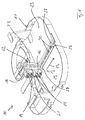
- FIG 1 shows a perspective view of a novel handling device 10 for connections between data transmission cables, especially for fiber optic connections between fiber optic cables, according to a first embodiment.
- the handling device 10 according to Figure 1 comprises a fixture 11 and a plurality of adapter modules 12.
- the fixture 11 may comprise one adapter module 12.
- Figure 1 shows the fixture 11 together with one adapter module 12.
- Figure 2 shows one adapter module 12.
- the plurality of adapter modules 12 are mounted side by side in a first direction 13 on the fixture 11.
- Each adapter module 12 is individually removable from the fixture 11 and individually mountable on the fixture 11.
- Each adapter module 12 comprises a plurality of adapters 14 arranged side by side in a second direction 15.
- the adapter module 12 shown in Figure 1 comprises four adapters 14, whereby each two adapters 12 have a common adapter housing 16.
- each adapter 14 can also comprise an individual adapter housing.
- the number of adapters 14 assigned to an adapter module 12 can be different. Further on, each adapter module 12 can comprise a single adapter.
- the adapters 14 having a common adapter housing 16 or having individual adapter housings are held by a basic body 17 of the respective adapter module 12.
- the basic body 17 provides openings 18 (see Figure 2 ) for receiving the adapters 14.
- the adapters 14 are configured to hold connectors and connect data transmission cables at a rear side 19 and a front side 20 of the respective adapter module 12.
- each adapter module 12 comprises holding legs 21, 22 being pivotably and flexibly connected in a middle portion 23 of the same by a connection element 24 being fixedly attached to both holding legs 21, 22.
- a first holding leg 21 is assigned to the rear side 19 of the respective adapter module 12 and a second holding leg 22 is assigned to the front side 20 of the respective adapter module 12.
- the holding legs 21, 22 define together the openings 18 for receiving and holding the adapters 14.
- the holding legs 21, 22 being pivotably connected in the middle portion 23 by the connection element 24 can be pivoted like legs of a clothespin.
- the distance between first ends 25 of the holding legs 21, 22 corresponds to the distance between second ends 26 of the same.
- the distance between first ends 25 of the holding legs 21, 22 is increased and the distance between second ends 26 of the holding legs 21, 22 is decreased. Accordingly, in the first, manually un-actuated position of the holding legs 21, 22 the distance between the first ends 25 of the holding legs 21, 22 is smaller than in the second, manually actuated position of the holding legs 21, 22. In the first, manually un-actuated position of the holding legs 21, 22 the distance between the second ends 26 of the holding legs 21, 22 is larger than in the second, manually actuated position of the holding legs 21, 22.
- the first ends 25 of the holding legs 21, 22 of the respective adapter module 12 comprise fixing hooks 28 acting together with holding means of the fixture 11 when the respective adapter module 12 is held on the fixture 11 in the first position of the holding legs 21, 22.
- the fixing hooks 28 are engaging with the holding means of the fixture 11 when the respective adapter module 12 is held on the fixture 11 in the first position of the holding legs 21, 22.
- the holding means of the fixture 11 are provided by mounting rails 27.
- the mounting rails 27 run in the first direction 13 and are fixed to a mounting surface 29 of the fixture 11.
- openings 30 are positioned between the mounting rails 27 of the fixture 11.
- the openings 30 are positioned side by side in the first direction 13.
- the openings 30 define the relative position of adapter modules 12 on the fixture 11 in such a way that a protrusion 31 of an inner leg 32 of the basic body 17 of the respective adapter module 12 being positioned between the holding legs 21, 22 protrudes into one of the openings 30 when the respective adapter module 12 is held on the fixture 11 in the first position of the holding legs 21, 22.
- the holding legs 20, 21 In order to remove the respective adapter module 12 from the fixture it is necessary to manually actuate the holding legs 20, 21 by pivoting the same into the second, manually actuated position. This can be done by manually pressing the second ends 26 of the holding legs 20, 21 together thereby increasing the distance between the first ends 25 of holding legs 20, 21 and thereby between the fixing hooks 28 so that the same disengage from the mounting rails 27 of the fixture 11.
- the second ends 26 of the holding legs 21, 22 of the respective adapter module 21 provide gripping elements for manually actuating the holding legs 21, 22 by manually pressing the gripping elements together.
- the holding legs 21, 22 When the gripping elements or the second ends 26 of the holding legs 21, 22 are not actuated, the holding legs 21, 22 automatically return to their first, manually un-actuated position due to the flexibility or elasticity of the material of the connection element 24.
- the adapter modules 12 are symmetrically in such a way that the inner leg 32 of the basic body 17 is positioned in the middle between the holding legs 21, 22 namely in the middle of the connecting element 24.
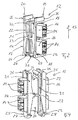
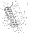
- Figure 3 and 4 show an embodiment in which the adapter modules 12 are asymmetrically in such a way that the inner leg 32 of the basic body 17 is not positioned in the middle of the connecting element 24 but is immediately adjacent to one of the holding legs, namely according to Figure 4 to the holding leg 22.
- both holding legs 21 and 22 are pivoted when pressing the second ends 26 of the holding legs 20, 21 together.
- Figures 3 and 4 illustrate an embodiment which facilitates the mounting of the adapter modules 12 on the fixture 11.
- the protrusion 31 of the inner leg 32 of the basic body 17 of the respective adapter module 12 is inserted into one of the openings 30 of the fixture 11.
- the fixing hooks 28 engage with the mounting rails 28 when the holding legs 21, 22 automatically return to their first, manually un-actuated position.
- the mounting openings 34 of the fixture 11 of the embodiment of Figures 3 and 4 are provided by a raised portion 33 of the mounting surface 29 of the fixture 11, whereby free space is provided below the raised portion 33 of the mounting surface 29.
- the mounting openings 34 serve to fix the adapter modules 12 on the fixture 11 and therefore provide the holding means for the adapter modules 12.
- the mounting openings 34 define the relative position of adapter modules 12 on the fixture 11.
- the mounting openings 34 are positioned side by side along parallel lines running in the first direction 13.
- At least two adapter modules 12 are stacked in such a way that the basic body 17 of a first, lower adapter module 12 is mounted on the fixture 11 and that the basic body 17 of a second, upper adapter module 12 is mounted on the basic body 17 of a first adapter module 12 and through the first adapter module 12 on the fixture 11.
- the fixing hooks 28 assigned to the first ends 25 of the holding legs 21, 22 of the basic body 17 of the second, upper adapter module 12 engage with the second ends 26 of the holding legs 21, 22 of the basic body 17 of the first, lower adapter module 12.
- the respective lower adapter module 12 is mounted on the fixture 11 by inserting the fixing hooks 28 assigned to the first ends 25 of the holding legs 21, 22 of the basic body 17 of the lower adapter module 12 into the mounting opening 34 provided by the fixture 11.
- the respective upper adapter module 12 is mounted on the respective lower adapter module 12 by inserting the fixing hooks 28 assigned to the first ends 25 of the holding legs 21, 22 of the basic body 17 of the upper adapter module 12 into openings 35 provided in the region of the second ends 26 of the holding legs 21, 22 of the basic body 17 of the lower adapter module 12. In this way it is possible to stack more than two adapter modules 12 above each other.
- the stacking of the adapter modules 12 allows to further increase the density of adapters 14 which can be arranged in a defined space.
Landscapes
- Physics & Mathematics (AREA)
- General Physics & Mathematics (AREA)
- Optics & Photonics (AREA)
- Light Guides In General And Applications Therefor (AREA)
- Mechanical Coupling Of Light Guides (AREA)
- Details Of Connecting Devices For Male And Female Coupling (AREA)
Priority Applications (1)
| Application Number | Priority Date | Filing Date | Title |
|---|---|---|---|
| EP15195832.9A EP3012675A3 (de) | 2011-06-29 | 2011-06-29 | Handhabungsvorrichtung für steckerverbindundsadapter für verbindungen zwischen datenübertragungskabeln |
Applications Claiming Priority (2)
| Application Number | Priority Date | Filing Date | Title |
|---|---|---|---|
| EP11171907.6A EP2541294B1 (de) | 2011-06-29 | 2011-06-29 | Fasersteckeradapterhalter mit Klemmvorrichtung |
| EP15195832.9A EP3012675A3 (de) | 2011-06-29 | 2011-06-29 | Handhabungsvorrichtung für steckerverbindundsadapter für verbindungen zwischen datenübertragungskabeln |
Related Parent Applications (2)
| Application Number | Title | Priority Date | Filing Date |
|---|---|---|---|
| EP11171907.6A Division EP2541294B1 (de) | 2011-06-29 | 2011-06-29 | Fasersteckeradapterhalter mit Klemmvorrichtung |
| EP11171907.6A Division-Into EP2541294B1 (de) | 2011-06-29 | 2011-06-29 | Fasersteckeradapterhalter mit Klemmvorrichtung |
Publications (2)
| Publication Number | Publication Date |
|---|---|
| EP3012675A2 true EP3012675A2 (de) | 2016-04-27 |
| EP3012675A3 EP3012675A3 (de) | 2016-08-10 |
Family
ID=44925703
Family Applications (2)
| Application Number | Title | Priority Date | Filing Date |
|---|---|---|---|
| EP15195832.9A Withdrawn EP3012675A3 (de) | 2011-06-29 | 2011-06-29 | Handhabungsvorrichtung für steckerverbindundsadapter für verbindungen zwischen datenübertragungskabeln |
| EP11171907.6A Not-in-force EP2541294B1 (de) | 2011-06-29 | 2011-06-29 | Fasersteckeradapterhalter mit Klemmvorrichtung |
Family Applications After (1)
| Application Number | Title | Priority Date | Filing Date |
|---|---|---|---|
| EP11171907.6A Not-in-force EP2541294B1 (de) | 2011-06-29 | 2011-06-29 | Fasersteckeradapterhalter mit Klemmvorrichtung |
Country Status (2)
| Country | Link |
|---|---|
| EP (2) | EP3012675A3 (de) |
| WO (1) | WO2013003167A2 (de) |
Families Citing this family (1)
| Publication number | Priority date | Publication date | Assignee | Title |
|---|---|---|---|---|
| EP3286588B1 (de) * | 2015-04-23 | 2020-01-29 | CommScope Connectivity Belgium BVBA | Telekommunikationstafelanordnung mit beweglichen adaptern |
Citations (1)
| Publication number | Priority date | Publication date | Assignee | Title |
|---|---|---|---|---|
| EP0740803B1 (de) | 1994-01-21 | 1999-01-27 | Adc Telecommunications, Inc. | Faserverteilungsgestell mit hoher packungsdichte |
Family Cites Families (13)
| Publication number | Priority date | Publication date | Assignee | Title |
|---|---|---|---|---|
| GB1338325A (en) * | 1971-07-09 | 1973-11-21 | United Carr Ltd | Fastener |
| JPH0241601Y2 (de) * | 1985-03-04 | 1990-11-06 | ||
| JPS62173911A (ja) * | 1986-01-27 | 1987-07-30 | フアナツク株式会社 | ケ−ブルクランプ装置 |
| US5078467A (en) * | 1991-02-07 | 1992-01-07 | Minnesota Mining And Manufacturing Company | Optical fiber connector including integral deformable housing and second-class levers |
| US5214735A (en) * | 1992-04-06 | 1993-05-25 | Adc Telecommunications, Inc. | Fiber optic connector retainer |
| US5581900A (en) * | 1995-05-30 | 1996-12-10 | Payne; Douglas | Level clamp |
| US5664800A (en) * | 1995-07-05 | 1997-09-09 | Morton International, Inc. | Retention system for attachment of a connector to an air bag reaction canister |
| US5734775A (en) * | 1996-02-06 | 1998-03-31 | Vidacovich; Kenneth John | Method and system for fiber optic splice activation and deactivation within an optical fiber distribution frame |
| US6354543B1 (en) * | 1999-01-12 | 2002-03-12 | Andrew Corporation | Stackable transmission line hanger |
| US20030063888A1 (en) * | 2001-10-01 | 2003-04-03 | Sahlin Jennifer J. | Channeling for use with light fiber |
| US7097142B1 (en) * | 2003-08-13 | 2006-08-29 | Beverly Manufacturing Company | One-piece resilient stackable hanger |
| IT1395161B1 (it) * | 2009-08-12 | 2012-09-05 | Fi Mo Tec Spa | Collare di supporto per articoli lungiformi, in particolare cavi, tubi e/o simili |
| EP2302430A1 (de) * | 2009-09-28 | 2011-03-30 | CCS Technology Inc. | Vorrichtung für die Aufnahme von mindestens einem Glasfaserkabel zugeordneten Unterbaugruppen und zur Befestigung derselben an einer Einrichtung |
-
2011
- 2011-06-29 EP EP15195832.9A patent/EP3012675A3/de not_active Withdrawn
- 2011-06-29 EP EP11171907.6A patent/EP2541294B1/de not_active Not-in-force
-
2012
- 2012-06-21 WO PCT/US2012/043427 patent/WO2013003167A2/en not_active Ceased
Patent Citations (1)
| Publication number | Priority date | Publication date | Assignee | Title |
|---|---|---|---|---|
| EP0740803B1 (de) | 1994-01-21 | 1999-01-27 | Adc Telecommunications, Inc. | Faserverteilungsgestell mit hoher packungsdichte |
Also Published As
| Publication number | Publication date |
|---|---|
| WO2013003167A3 (en) | 2013-03-07 |
| EP2541294A1 (de) | 2013-01-02 |
| WO2013003167A2 (en) | 2013-01-03 |
| EP3012675A3 (de) | 2016-08-10 |
| EP2541294B1 (de) | 2016-01-20 |
Similar Documents
| Publication | Publication Date | Title |
|---|---|---|
| EP3844973B1 (de) | Rahmenanordnungen für optische faserverteilungselemente | |
| EP3845044B1 (de) | Rahmenanordnungen für optische faserverteilungselemente | |
| EP3844972B1 (de) | Rahmenanordnungen für glasfaserverteilungselemente | |
| US7734139B2 (en) | Modular cable-management system | |
| EP1883844B1 (de) | Glasfaser-splittermodul | |
| US9182563B2 (en) | Adapter plate for fiber optic module | |
| EP2464999B1 (de) | Faserführungskomponente | |
| WO2020043909A1 (en) | Frame assemblies for optical fiber distribution elements | |
| US12007615B2 (en) | Frame assemblies for optical fiber distribution elements | |
| US8221169B2 (en) | Fanning module, fanning strip, and cable management panel | |
| EP4737969A2 (de) | Faseroptische ablagesysteme | |
| US11947177B2 (en) | Frame assemblies for optical fiber distribution elements | |
| US9459426B2 (en) | Optical plenum | |
| EP3012675A2 (de) | Handhabungsvorrichtung für steckerverbindundsadapter für verbindungen zwischen datenübertragungskabeln | |
| US9551440B2 (en) | Cable management clasp for a cable assembly of a communication system | |
| US6582133B2 (en) | Module and method for interconnecting optoelectronic cards | |
| EP4094107B1 (de) | Kabelabschlusseinheiten für optische faserverteilungselemente | |
| EP2541293B1 (de) | Adapterträger für Faserstecker mit Klemmpin, der in Klemmbasis empfangen wird | |
| WO2012027627A2 (en) | Communications enclosure having rear mounted bracket and method of securing a cable bundle to a communications enclosure using a rear mounted bracket | |
| WO2015095365A1 (en) | Fiber optic splice tray | |
| EP2302430A1 (de) | Vorrichtung für die Aufnahme von mindestens einem Glasfaserkabel zugeordneten Unterbaugruppen und zur Befestigung derselben an einer Einrichtung | |
| CA2349494C (en) | Module and method for interconnecting optoelectronic cards | |
| WO2014049146A2 (en) | Fiber optic cable holder and method |
Legal Events
| Date | Code | Title | Description |
|---|---|---|---|
| PUAI | Public reference made under article 153(3) epc to a published international application that has entered the european phase |
Free format text: ORIGINAL CODE: 0009012 |
|
| AC | Divisional application: reference to earlier application |
Ref document number: 2541294 Country of ref document: EP Kind code of ref document: P |
|
| AK | Designated contracting states |
Kind code of ref document: A2 Designated state(s): AL AT BE BG CH CY CZ DE DK EE ES FI FR GB GR HR HU IE IS IT LI LT LU LV MC MK MT NL NO PL PT RO RS SE SI SK SM TR |
|
| PUAL | Search report despatched |
Free format text: ORIGINAL CODE: 0009013 |
|
| AK | Designated contracting states |
Kind code of ref document: A3 Designated state(s): AL AT BE BG CH CY CZ DE DK EE ES FI FR GB GR HR HU IE IS IT LI LT LU LV MC MK MT NL NO PL PT RO RS SE SI SK SM TR |
|
| RIC1 | Information provided on ipc code assigned before grant |
Ipc: G02B 6/44 20060101AFI20160705BHEP |
|
| 17P | Request for examination filed |
Effective date: 20170209 |
|
| RBV | Designated contracting states (corrected) |
Designated state(s): AL AT BE BG CH CY CZ DE DK EE ES FI FR GB GR HR HU IE IS IT LI LT LU LV MC MK MT NL NO PL PT RO RS SE SI SK SM TR |
|
| GRAP | Despatch of communication of intention to grant a patent |
Free format text: ORIGINAL CODE: EPIDOSNIGR1 |
|
| INTG | Intention to grant announced |
Effective date: 20191202 |
|
| RAP1 | Party data changed (applicant data changed or rights of an application transferred) |
Owner name: CCS TECHNOLOGY, INC. |
|
| STAA | Information on the status of an ep patent application or granted ep patent |
Free format text: STATUS: THE APPLICATION IS DEEMED TO BE WITHDRAWN |
|
| 18D | Application deemed to be withdrawn |
Effective date: 20200603 |