EP3012430A1 - Variable fan immersion system for optimal fan efficiency - Google Patents
Variable fan immersion system for optimal fan efficiency Download PDFInfo
- Publication number
- EP3012430A1 EP3012430A1 EP15191201.1A EP15191201A EP3012430A1 EP 3012430 A1 EP3012430 A1 EP 3012430A1 EP 15191201 A EP15191201 A EP 15191201A EP 3012430 A1 EP3012430 A1 EP 3012430A1
- Authority
- EP
- European Patent Office
- Prior art keywords
- cooling fan
- variable
- immersion
- machine
- engine
- Prior art date
- Legal status (The legal status is an assumption and is not a legal conclusion. Google has not performed a legal analysis and makes no representation as to the accuracy of the status listed.)
- Withdrawn
Links
- 238000007654 immersion Methods 0.000 title claims abstract description 110
- 238000001816 cooling Methods 0.000 claims abstract description 247
- 239000002826 coolant Substances 0.000 claims description 4
- 239000003570 air Substances 0.000 description 12
- 238000002485 combustion reaction Methods 0.000 description 7
- 239000012080 ambient air Substances 0.000 description 3
- 230000004323 axial length Effects 0.000 description 3
- 230000005540 biological transmission Effects 0.000 description 3
- 238000004378 air conditioning Methods 0.000 description 2
- 239000010720 hydraulic oil Substances 0.000 description 2
- 239000003921 oil Substances 0.000 description 2
- 241001124569 Lycaenidae Species 0.000 description 1
- 238000010276 construction Methods 0.000 description 1
- 239000000446 fuel Substances 0.000 description 1
- 230000003137 locomotive effect Effects 0.000 description 1
- 230000035515 penetration Effects 0.000 description 1
- 230000003134 recirculating effect Effects 0.000 description 1
Images



Classifications
-
- F—MECHANICAL ENGINEERING; LIGHTING; HEATING; WEAPONS; BLASTING
- F01—MACHINES OR ENGINES IN GENERAL; ENGINE PLANTS IN GENERAL; STEAM ENGINES
- F01P—COOLING OF MACHINES OR ENGINES IN GENERAL; COOLING OF INTERNAL-COMBUSTION ENGINES
- F01P7/00—Controlling of coolant flow
- F01P7/02—Controlling of coolant flow the coolant being cooling-air
- F01P7/06—Controlling of coolant flow the coolant being cooling-air by varying blade pitch
-
- F—MECHANICAL ENGINEERING; LIGHTING; HEATING; WEAPONS; BLASTING
- F01—MACHINES OR ENGINES IN GENERAL; ENGINE PLANTS IN GENERAL; STEAM ENGINES
- F01P—COOLING OF MACHINES OR ENGINES IN GENERAL; COOLING OF INTERNAL-COMBUSTION ENGINES
- F01P11/00—Component parts, details, or accessories not provided for in, or of interest apart from, groups F01P1/00 - F01P9/00
- F01P11/12—Filtering, cooling, or silencing cooling-air
-
- F—MECHANICAL ENGINEERING; LIGHTING; HEATING; WEAPONS; BLASTING
- F01—MACHINES OR ENGINES IN GENERAL; ENGINE PLANTS IN GENERAL; STEAM ENGINES
- F01P—COOLING OF MACHINES OR ENGINES IN GENERAL; COOLING OF INTERNAL-COMBUSTION ENGINES
- F01P5/00—Pumping cooling-air or liquid coolants
- F01P5/02—Pumping cooling-air; Arrangements of cooling-air pumps, e.g. fans or blowers
- F01P5/06—Guiding or ducting air to, or from, ducted fans
-
- F—MECHANICAL ENGINEERING; LIGHTING; HEATING; WEAPONS; BLASTING
- F01—MACHINES OR ENGINES IN GENERAL; ENGINE PLANTS IN GENERAL; STEAM ENGINES
- F01P—COOLING OF MACHINES OR ENGINES IN GENERAL; COOLING OF INTERNAL-COMBUSTION ENGINES
- F01P7/00—Controlling of coolant flow
- F01P7/02—Controlling of coolant flow the coolant being cooling-air
- F01P7/04—Controlling of coolant flow the coolant being cooling-air by varying pump speed, e.g. by changing pump-drive gear ratio
-
- F—MECHANICAL ENGINEERING; LIGHTING; HEATING; WEAPONS; BLASTING
- F04—POSITIVE - DISPLACEMENT MACHINES FOR LIQUIDS; PUMPS FOR LIQUIDS OR ELASTIC FLUIDS
- F04D—NON-POSITIVE-DISPLACEMENT PUMPS
- F04D29/00—Details, component parts, or accessories
- F04D29/05—Shafts or bearings, or assemblies thereof, specially adapted for elastic fluid pumps
- F04D29/052—Axially shiftable rotors
Definitions
- the present invention relates to fans for heat exchangers, and, more particularly, to cooling fans for radiators for internal combustion engines.
- a cooling fan for an internal combustion engine is typically mounted proximate to a heat exchanger, generally a coolant to air heat exchanger known as a radiator.
- a heat exchanger generally a coolant to air heat exchanger known as a radiator.
- additional heat exchangers such as a charge air to ambient air heat exchanger, an exhaust gas recirculation heat exchanger, a transmission oil heat exchanger, a hydraulic oil heat exchanger, or an air conditioning condenser, are mounted in conjunction with the radiator.
- a fan shroud adjoins the fan side of the heat exchanger combination, which directs cooling ambient air over the entire surface of the heat exchanger, and which prevents inefficient recirculating flow of cooling air through the cooling fan.
- the cooling fan is mounted in relation to the fan shroud such that it is located partially within the fan shroud along its axial length, and partially outside the fan shroud.
- the proportion of the axial length of the cooling fan that is within the fan shroud is referred to as the depth or percentage of fan immersion.
- the depth or percentage of fan immersion has a large impact on the efficiency of the cooling fan in terms of volumetric air movement for a given amount of power consumption.
- the amount of fan immersion may be fixed according to an efficiency that is optimized for the average operating parameters of the machine or vehicle incorporating the internal combustion engine, i.e. - for a given ratio between the machine or vehicle forward speed and engine speed when the machine or vehicle is, for example, in high gear.
- cooling fan efficiency in order to move a maximum amount of air with a minimum amount of cooling fan power consumption.
- the amount of power used to drive a cooling fan is not inconsiderable, and can be as much as seventy horsepower in a large commercial vehicle or similar application.
- the necessary heat rejection may take place with a heat exchanger or exchangers that are subject to physical size constraints due to aerodynamic or aesthetic considerations. In order to accomplish these ends, it is known to utilize a variable pitch cooling fan.
- the present invention provides a variable cooling fan immersion system for use with a variable pitch cooling fan or with a variable speed cooling fan drive, or both.
- the invention in one form is directed to a machine having an internal combustion engine, which is provided with a variable cooling fan immersion system including a variable cooling fan immersion depth adjustment mechanism and a variable pitch cooling fan.
- the invention in another form is directed to a variable cooling fan immersion system including a variable cooling fan immersion depth adjustment mechanism and a variable pitch cooling fan.
- the invention in yet another form is directed to a variable cooling fan immersion system including a variable cooling fan immersion depth adjustment mechanism and a variable speed cooling fan drive.
- An advantage of the present invention is that the efficiency of a variable pitch cooling fan can be maintained and optimized relative to the percentage of cooling fan immersion as the angle of the variable pitch cooling fan blade angle changes. This efficiency may be maximized by maintaining the variable pitch cooling fan at a fixed percentage of immersion throughout the range of variable pitch cooling fan blade angles, or may alternately be maximized by adjusting the percentage of immersion as a function of the variable pitch cooling fan blade angle and one or more additional factors.
- Another advantage is that the efficiency of a variable speed cooling fan drive can be maintained and optimized relative to the percentage of cooling fan immersion as the cooling fan rotational speed to engine rotational speed ratio changes.
- FIG. 1 there is shown an embodiment of a vehicle or machine 10 of the present invention.
- the embodiment shown is a forward travelling machine, such as a road-going vehicle.
- this embodiment is illustrative only, and the present invention may be embodied in any number of machines utilizing an internal combustion engine and heat exchanger, such as agricultural machines like tractors and combine harvesters, construction machines like bulldozers and excavators, rail-going machines like locomotives, or non-moving machines like stationary power generators.
- the vehicle or machine 10 is provided with an engine 16 and a vehicle cooling system 12.
- the vehicle cooling system 12 is made up of one or more heat exchangers 14, which may include a coolant to air heat exchanger known as a radiator, and may additionally include a charge air to ambient air heat exchanger, an exhaust gas recirculation heat exchanger, a transmission oil heat exchanger, a hydraulic oil heat exchanger, or an air conditioning condenser.
- a cooling fan 20 is located adjacent to the heat exchanger 14, and serves in this embodiment to draw air through the heat exchanger 14. Alternate embodiments may be so configured that the vehicle cooling system 12 is located elsewhere in the vehicle or machine 10, such as in the rear of the vehicle or machine 10, laterally in the side of the vehicle or machine 10, or horizontally in the top of the vehicle or machine 10. In these alternate embodiments, the cooling fan 20 may either function to draw air through the heat exchanger 14 or to blow air through the heat exchanger 14.
- the cooling fan 20 in the embodiment of Fig. 1 is driven by a cooling fan drive 32, which is shown to be directly driven by the engine 16.
- a cooling fan drive 32 may be directly driven with a fixed rotation ratio with the engine 16, directly driven with a passively variable rotation ratio with the engine 16, directly driven with an actively variable rotation ratio with the engine 16, hydraulically driven with fixed or variable rotation ratio with the engine 16, pneumatically driven with fixed or variable rotation ratio with the engine 16, or electrically driven with a fixed rate of rotation, or in fixed or variable rotation ratio with the engine 16.
- a fan shroud 18 is provided between the heat exchanger 14 and the cooling fan 20, which fan shroud 18 closely abuts the ends of the cooling fan blades 22 of the cooling fan 20.
- the depth to which the cooling fan 20 penetrates axially into the space enclosed by the fan shroud 18 is critical to the performance of the cooling fan 20 in terms of volumetric airflow and resultant performance of the vehicle cooling system 12, versus the amount of power consumed by the cooling fan 20.
- This amount of axial penetration of the cooling fan 20 is referred to as the percentage of cooling fan immersion or cooling fan immersion depth.
- the amount of the axial length of the cooling fan 20 that does not penetrate the space enclosed by the fan shroud 18 will be referred to as the percentage of cooling fan protrusion or cooling fan protrusion height.
- the percentage of cooling fan 20 immersion can be optimized, because there is only one percentage of cooling fan immersion set point that optimizes cooling fan power consumption to volumetric airflow rate through the vehicle cooling system 12.
- This optimized percentage of cooling fan immersion for a cooling fan 20 that is both fixed in its rotation ratio with the engine 16 and fixed in the pitch of its cooling fan blades 22 is typically about sixty three percent.
- variable speed cooling fan In a vehicle cooling system 12 that uses a variable speed cooling fan drive, this is because the percentage of cooling fan immersion that is optimal over the full range of engine 16 rotational speeds may not be optimal at one or more rotational speeds at which the variable speed cooling fan drive is configured to operate. In a vehicle cooling system 12 that uses a variable pitch cooling fan, this is because the percentage of cooling fan immersion that is optimal at one variable pitch cooling fan blade angle may not be optimal at a different variable pitch cooling fan blade angle. This is especially true on variable pitch cooling fans that have a percentage of cooling fan immersion that places the midline about which the variable pitch cooling fan blades rotate at a location other than the plane of the opening of the fan shroud 18.
- Figs. 2 through 5 show cross sectional side views of a vehicle cooling system 12 and variable cooling fan immersion system 44.
- the vehicle cooling system 12 is again provided with at least one heat exchanger 14 and a fan shroud 18, which fan shroud 18 closely abuts the ends of the cooling fan blades 22 of the cooling fan 20, or as in Fig. 5 closely abuts the ends of the variable pitch cooling fan blades 26 of the variable pitch cooling fan 24.
- the variable cooling fan immersion system 44 incorporates a variable cooling fan immersion depth adjustment mechanism 46, which serves to move the cooling fan 20 or variable pitch cooling fan 24 along its cooling fan axis 36 further in or further out of the space enclosed by the fan shroud 18.
- the percentage of cooling fan immersion or cooling fan immersion depth is represented by item number 40, and the percentage of cooling fan protrusion or cooling fan protrusion height is represented by item number 42.
- the cooling fan 20 is approximately centered in the plane of the opening of the fan shroud 18.
- the cooling fan 20 is moved to a location of greater percentage of cooling fan immersion 40.
- the cooling fan 20 is moved to a location of lesser percentage of cooling fan immersion 40.
- Fig. 5 illustrates the principle that, for a variable pitch cooling fan 24 having the midline about which the variable pitch cooling fan blades 26 rotate at a location other than the plane of the opening of the fan shroud 18, changing the variable pitch cooling fan blade angle and the resultant overall length of the variable pitch cooling fan 24 along its cooling fan axis 36, varies the percentage of cooling fan immersion 40.
- the variable pitch cooling fan 24 having its variable pitch cooling fan blades 26 at a steep pitch is represented by the solid line fan outline, with resulting cooling fan immersion depth 40 and cooling fan protrusion height 42.
- the proportion of cooling fan immersion depth 40 to cooling fan protrusion height 42 is relatively large.
- variable pitch cooling fan 24 having its variable pitch cooling fan blades 26 at a shallow pitch is represented by the dotted line fan outline, with resulting cooling fan immersion depth 40' and cooling fan protrusion height 42'.
- the proportion of cooling fan immersion depth 40' to cooling fan protrusion height 42' is relatively small, and could even go to zero.
- Fig. 6 shows a variable pitch cooling fan 24 connected to a variable cooling fan immersion system 44 of the present invention.
- the variable pitch cooling fan 24 is provided with variable pitch cooling fan blades 26 which are rotatable to various variable pitch cooling fan blade angles 28 by means of variable pitch cooling fan blade actuators 30.
- the variable pitch cooling fan 24 rotates around its cooling fan axis 36, and is connected to a variable cooling fan immersion depth adjustment mechanism 46 of the variable cooling fan immersion system 44.
- the variable cooling fan immersion depth adjustment mechanism 46 has a hydraulic connection 52, by which it moves the variable pitch cooling fan 24 along its cooling fan axis 36 further in or further out of the space enclosed by the fan shroud 18, thereby changing the cooling fan immersion depth 40 and cooling fan protrusion height 42.
- Figs. 7A, 7B, and 7C are cross sectional side views of an embodiment of a variable cooling fan immersion depth adjustment mechanism 46 used in the variable cooling fan immersion system 44 of the present invention.
- the variable cooling fan immersion depth adjustment mechanism 46 is provided with a hydraulic device 50 with an inner hub 58 and an outer hub 60, which together define a hydraulic actuator 48.
- Hydraulic cylinder seals 54 provide sliding engagement between the inner hub 58 and the outer hub 60, while a drive spline 62 provides torsional communication between the inner hub 58 and the outer hub 60.
- a hydraulic connection 52 communicates hydraulic pressure to the hydraulic actuator 48, which then acts against a return spring 56 to move the variable pitch cooling fan along its cooling fan axis.
- a cooling fan position sensor 70 is provided, by which the variable cooling fan immersion system 44 receives feedback on the state of the variable cooling fan immersion depth adjustment mechanism 46.
- Fig. 7A shows the variable cooling fan immersion depth adjustment mechanism 46 in a position of zero percent cooling fan immersion.
- Fig. 7B shows the variable cooling fan immersion depth adjustment mechanism 46 in a position of fifty percent cooling fan immersion.
- Fig. 7C shows the variable cooling fan immersion depth adjustment mechanism 46 in a position of one hundred percent cooling fan immersion.
- Fig. 8 is a detail cross sectional side view of an embodiment of a variable cooling fan immersion depth adjustment mechanism 46 used in the variable cooling fan immersion system 44 of the present invention.
- the variable cooling fan immersion depth adjustment mechanism 46 of Fig. 8 is provided with a hydraulic device 50 with an inner hub 58 and an outer hub 60, which together define a hydraulic actuator 48.
- Hydraulic cylinder seals 54 provide sliding engagement between the inner hub 58 and the outer hub 60, while a drive spline 62 provides torsional communication between the inner hub 58 and the outer hub 60.
- a hydraulic connection 52 communicates hydraulic pressure to the hydraulic actuator 48, which then acts against a return spring 56 to move the variable pitch cooling fan along its cooling fan axis.
- a cooling fan position sensor 70 is provided, by which the variable cooling fan immersion system receives feedback on the state of the variable cooling fan immersion depth adjustment mechanism 46.
- variable cooling fan immersion system 44 of the present invention incorporates a variable cooling fan immersion control system 68 connected to the variable cooling fan immersion depth adjustment mechanism 46 as shown in Fig. 9 .
- the variable cooling fan immersion control system 68 solves the problem of having the percentage of cooling fan immersion depend fixedly and detrimentally upon the variable pitch cooling fan blade angle as has been illustrated in Fig. 5 , and further provides additional advantages of being able to control the percentage of cooling fan immersion as an optimized function of one or both of the variable pitch cooling fan blade angle and the variable speed cooling fan drive ratio.
- This optimized function may maintain the percentage of cooling fan immersion at a fixed value throughout a range of variable pitch cooling fan blade angles when the location of the midline about which the variable pitch cooling fan blades rotate is other than the plane of the opening of the fan shroud.
- the optimized function utilized by the variable cooling fan immersion control system 68 may set the percentage of cooling fan immersion to a value that correlates with a maximum efficiency derived from the variable pitch cooling fan blade angles or the variable speed cooling fan drive ratio, or both. Furthermore, the variable cooling fan immersion control system 68 may derive the percentage of cooling fan immersion that correlates with a maximum efficiency from additional factors, such as input from a vehicle speed sensor 76, an engine rotational speed sensor 78, a coolant temperature sensor 80, calculated engine power output, and ambient temperature and atmospheric pressure. In order to determine the percentage of cooling fan immersion to a value that correlates with a maximum efficiency, the variable cooling fan immersion control system 68 may utilize a look-up table 74.
Landscapes
- Engineering & Computer Science (AREA)
- Mechanical Engineering (AREA)
- General Engineering & Computer Science (AREA)
- Chemical & Material Sciences (AREA)
- Combustion & Propulsion (AREA)
- Structures Of Non-Positive Displacement Pumps (AREA)
- Cooling, Air Intake And Gas Exhaust, And Fuel Tank Arrangements In Propulsion Units (AREA)
Abstract
Description
- The present invention relates to fans for heat exchangers, and, more particularly, to cooling fans for radiators for internal combustion engines.
- A cooling fan for an internal combustion engine is typically mounted proximate to a heat exchanger, generally a coolant to air heat exchanger known as a radiator. Often, one or more additional heat exchangers, such as a charge air to ambient air heat exchanger, an exhaust gas recirculation heat exchanger, a transmission oil heat exchanger, a hydraulic oil heat exchanger, or an air conditioning condenser, are mounted in conjunction with the radiator. In order to provide for efficient cooling of these heat exchangers, a fan shroud adjoins the fan side of the heat exchanger combination, which directs cooling ambient air over the entire surface of the heat exchanger, and which prevents inefficient recirculating flow of cooling air through the cooling fan.
- The cooling fan is mounted in relation to the fan shroud such that it is located partially within the fan shroud along its axial length, and partially outside the fan shroud. The proportion of the axial length of the cooling fan that is within the fan shroud is referred to as the depth or percentage of fan immersion. The depth or percentage of fan immersion has a large impact on the efficiency of the cooling fan in terms of volumetric air movement for a given amount of power consumption. For a cooling fan for an internal combustion engine that has a rotational speed that is either in a direct relationship to an engine rotational speed, or that has a rotational speed that is entirely fixed, such as an electrically driven fan, and that also has a fixed pitch of its cooling fan blades, the amount of fan immersion may be fixed according to an efficiency that is optimized for the average operating parameters of the machine or vehicle incorporating the internal combustion engine, i.e. - for a given ratio between the machine or vehicle forward speed and engine speed when the machine or vehicle is, for example, in high gear.
- It is also known, for example in
US8408170 (Kardos, et al ), to provide a cooling fan that is moveable axially during vehicle operation, which axial movement is proportionate to the fan speed, which is itself in fixed proportion to the engine speed. Another reference,US4387780 (Fujikawa ), describes a cooling fan that is also moveable axially during vehicle operation, with the axial movement being associated with the moveable sheave of a variable speed drive. However, the variable speed drive does not vary the speed of the fan relative to the engine speed, but is merely a variable speed final drive for propulsion of the vehicle, e.g. - a variable speed transmission. - As various machines and vehicles utilizing internal combustion engines and vehicle cooling systems become increasingly efficient, both in terms of fuel efficiency and in terms of exhaust emissions, it is desirable to maximize cooling fan efficiency, in order to move a maximum amount of air with a minimum amount of cooling fan power consumption. The amount of power used to drive a cooling fan is not inconsiderable, and can be as much as seventy horsepower in a large commercial vehicle or similar application. Furthermore, the necessary heat rejection may take place with a heat exchanger or exchangers that are subject to physical size constraints due to aerodynamic or aesthetic considerations. In order to accomplish these ends, it is known to utilize a variable pitch cooling fan.
- The present invention provides a variable cooling fan immersion system for use with a variable pitch cooling fan or with a variable speed cooling fan drive, or both.
- The invention in one form is directed to a machine having an internal combustion engine, which is provided with a variable cooling fan immersion system including a variable cooling fan immersion depth adjustment mechanism and a variable pitch cooling fan.
- The invention in another form is directed to a variable cooling fan immersion system including a variable cooling fan immersion depth adjustment mechanism and a variable pitch cooling fan.
- The invention in yet another form is directed to a variable cooling fan immersion system including a variable cooling fan immersion depth adjustment mechanism and a variable speed cooling fan drive.
- An advantage of the present invention is that the efficiency of a variable pitch cooling fan can be maintained and optimized relative to the percentage of cooling fan immersion as the angle of the variable pitch cooling fan blade angle changes. This efficiency may be maximized by maintaining the variable pitch cooling fan at a fixed percentage of immersion throughout the range of variable pitch cooling fan blade angles, or may alternately be maximized by adjusting the percentage of immersion as a function of the variable pitch cooling fan blade angle and one or more additional factors.
- Another advantage is that the efficiency of a variable speed cooling fan drive can be maintained and optimized relative to the percentage of cooling fan immersion as the cooling fan rotational speed to engine rotational speed ratio changes.
- The above-mentioned and other features and advantages of this invention, and the manner of attaining them, will become more apparent and the invention will be better understood by reference to the following description of an embodiment of the invention taken in conjunction with the accompanying drawings, wherein:
-
Fig. 1 is a top perspective view of an embodiment of a machine having an engine of the present invention, in the form of a vehicle with an engine, a vehicle cooling system with a heat exchanger and a fan shroud, and a cooling fan; -
Fig. 2 is a cross sectional side view of the vehicle cooling system ofFig. 1 , showing the heat exchanger, the fan shroud, the cooling fan, and a variable cooling fan immersion system, and also illustrating the percentage of cooling fan immersion and the percentage of cooling fan protrusion; -
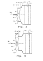
Fig. 3 is a cross sectional side view of the vehicle cooling system and variable cooling fan immersion system ofFig. 2 , illustrating the variable cooling fan immersion system in a position of proportionately great cooling fan immersion; -
Fig. 4 is a cross sectional side view of the vehicle cooling system and variable cooling fan immersion system ofFigs. 2 and3 , illustrating the variable cooling fan immersion system in a position of proportionately small cooling fan immersion; -
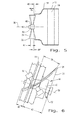
Fig. 5 is a cross sectional side view of a vehicle cooling system and variable cooling fan immersion system, similar toFigs. 2 through 4 , illustrating variation in the percentage of cooling fan immersion as a result of changing variable pitch fan blade angles when using a variable pitch cooling fan; -
Fig. 6 is a side view of a variable cooling fan immersion system with a variable cooling fan immersion depth adjustment mechanism and a variable pitch cooling fan; -
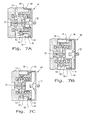
Fig. 7A is a cross sectional side view of an embodiment of a variable cooling fan immersion depth adjustment mechanism used in the variable cooling fan immersion system of the present invention, shown in a position of zero percent cooling fan immersion; -
Fig. 7B is a cross sectional side view of the variable cooling fan immersion depth adjustment mechanism shown inFig. 7A , now shown in a position of fifty percent cooling fan immersion; -
Fig. 7C is a cross sectional side view of the variable cooling fan immersion depth adjustment mechanism shown inFigs. 7A and 7B , now shown in a position of one hundred percent cooling fan immersion; -
Fig. 8 is a detail cross sectional view of another embodiment of a variable cooling fan immersion depth adjustment mechanism used in the variable cooling fan immersion system of the present invention; and -
Fig. 9 is an illustration of a variable cooling fan immersion control system. - Corresponding reference characters indicate corresponding parts throughout the several views. The exemplification set out herein illustrates embodiment of the invention, in one form, and such exemplification is not to be construed as limiting the scope of the invention in any manner.
- Referring now to the drawings, and more particularly
Fig. 1 , there is shown an embodiment of a vehicle ormachine 10 of the present invention. The embodiment shown is a forward travelling machine, such as a road-going vehicle. However, this embodiment is illustrative only, and the present invention may be embodied in any number of machines utilizing an internal combustion engine and heat exchanger, such as agricultural machines like tractors and combine harvesters, construction machines like bulldozers and excavators, rail-going machines like locomotives, or non-moving machines like stationary power generators. The vehicle ormachine 10 is provided with anengine 16 and avehicle cooling system 12. Thevehicle cooling system 12 is made up of one ormore heat exchangers 14, which may include a coolant to air heat exchanger known as a radiator, and may additionally include a charge air to ambient air heat exchanger, an exhaust gas recirculation heat exchanger, a transmission oil heat exchanger, a hydraulic oil heat exchanger, or an air conditioning condenser. Acooling fan 20 is located adjacent to theheat exchanger 14, and serves in this embodiment to draw air through theheat exchanger 14. Alternate embodiments may be so configured that thevehicle cooling system 12 is located elsewhere in the vehicle ormachine 10, such as in the rear of the vehicle ormachine 10, laterally in the side of the vehicle ormachine 10, or horizontally in the top of the vehicle ormachine 10. In these alternate embodiments, thecooling fan 20 may either function to draw air through theheat exchanger 14 or to blow air through theheat exchanger 14. - The
cooling fan 20 in the embodiment ofFig. 1 is driven by a cooling fan drive 32, which is shown to be directly driven by theengine 16. Alternate embodiments of the cooling fan drive 32 may be directly driven with a fixed rotation ratio with theengine 16, directly driven with a passively variable rotation ratio with theengine 16, directly driven with an actively variable rotation ratio with theengine 16, hydraulically driven with fixed or variable rotation ratio with theengine 16, pneumatically driven with fixed or variable rotation ratio with theengine 16, or electrically driven with a fixed rate of rotation, or in fixed or variable rotation ratio with theengine 16. - In order to direct air flow through the entirety of the surface of the
heat exchanger 14 and to prevent unwanted and inefficient air recirculation through thecooling fan 20, afan shroud 18 is provided between theheat exchanger 14 and thecooling fan 20, whichfan shroud 18 closely abuts the ends of thecooling fan blades 22 of thecooling fan 20. The depth to which thecooling fan 20 penetrates axially into the space enclosed by thefan shroud 18 is critical to the performance of thecooling fan 20 in terms of volumetric airflow and resultant performance of thevehicle cooling system 12, versus the amount of power consumed by thecooling fan 20. This amount of axial penetration of thecooling fan 20 is referred to as the percentage of cooling fan immersion or cooling fan immersion depth. For the sake of discussion, the amount of the axial length of thecooling fan 20 that does not penetrate the space enclosed by thefan shroud 18 will be referred to as the percentage of cooling fan protrusion or cooling fan protrusion height. - For a
cooling fan 20 that is both fixed in its rotation ratio with theengine 16 and fixed in the pitch of itscooling fan blades 22, the percentage ofcooling fan 20 immersion can be optimized, because there is only one percentage of cooling fan immersion set point that optimizes cooling fan power consumption to volumetric airflow rate through thevehicle cooling system 12. This optimized percentage of cooling fan immersion for acooling fan 20 that is both fixed in its rotation ratio with theengine 16 and fixed in the pitch of itscooling fan blades 22 is typically about sixty three percent. However, a problem arises when a variable pitch cooling fan or when a variable speed cooling fan drive, or both, is used in the design of thevehicle cooling system 12. In avehicle cooling system 12 that uses a variable speed cooling fan drive, this is because the percentage of cooling fan immersion that is optimal over the full range ofengine 16 rotational speeds may not be optimal at one or more rotational speeds at which the variable speed cooling fan drive is configured to operate. In avehicle cooling system 12 that uses a variable pitch cooling fan, this is because the percentage of cooling fan immersion that is optimal at one variable pitch cooling fan blade angle may not be optimal at a different variable pitch cooling fan blade angle. This is especially true on variable pitch cooling fans that have a percentage of cooling fan immersion that places the midline about which the variable pitch cooling fan blades rotate at a location other than the plane of the opening of thefan shroud 18. -
Figs. 2 through 5 show cross sectional side views of avehicle cooling system 12 and variable coolingfan immersion system 44. Thevehicle cooling system 12 is again provided with at least oneheat exchanger 14 and afan shroud 18, whichfan shroud 18 closely abuts the ends of the coolingfan blades 22 of the coolingfan 20, or as inFig. 5 closely abuts the ends of the variable pitch coolingfan blades 26 of the variablepitch cooling fan 24. The variable coolingfan immersion system 44 incorporates a variable cooling fan immersiondepth adjustment mechanism 46, which serves to move the coolingfan 20 or variablepitch cooling fan 24 along its coolingfan axis 36 further in or further out of the space enclosed by thefan shroud 18. The percentage of cooling fan immersion or cooling fan immersion depth is represented byitem number 40, and the percentage of cooling fan protrusion or cooling fan protrusion height is represented byitem number 42. InFig. 2 , the coolingfan 20 is approximately centered in the plane of the opening of thefan shroud 18. InFig. 3 , the coolingfan 20 is moved to a location of greater percentage of coolingfan immersion 40. InFig. 4 , the coolingfan 20 is moved to a location of lesser percentage of coolingfan immersion 40. -
Fig. 5 illustrates the principle that, for a variablepitch cooling fan 24 having the midline about which the variable pitch coolingfan blades 26 rotate at a location other than the plane of the opening of thefan shroud 18, changing the variable pitch cooling fan blade angle and the resultant overall length of the variablepitch cooling fan 24 along its coolingfan axis 36, varies the percentage of coolingfan immersion 40. Specifically, the variablepitch cooling fan 24 having its variable pitch coolingfan blades 26 at a steep pitch is represented by the solid line fan outline, with resulting coolingfan immersion depth 40 and coolingfan protrusion height 42. As can be seen, the proportion of coolingfan immersion depth 40 to coolingfan protrusion height 42 is relatively large. The variablepitch cooling fan 24 having its variable pitch coolingfan blades 26 at a shallow pitch is represented by the dotted line fan outline, with resulting cooling fan immersion depth 40' and cooling fan protrusion height 42'. As can be seen, the proportion of cooling fan immersion depth 40' to cooling fan protrusion height 42' is relatively small, and could even go to zero. -
Fig. 6 shows a variablepitch cooling fan 24 connected to a variable coolingfan immersion system 44 of the present invention. The variablepitch cooling fan 24 is provided with variable pitch coolingfan blades 26 which are rotatable to various variable pitch cooling fan blade angles 28 by means of variable pitch coolingfan blade actuators 30. The variablepitch cooling fan 24 rotates around its coolingfan axis 36, and is connected to a variable cooling fan immersiondepth adjustment mechanism 46 of the variable coolingfan immersion system 44. The variable cooling fan immersiondepth adjustment mechanism 46 has ahydraulic connection 52, by which it moves the variablepitch cooling fan 24 along its coolingfan axis 36 further in or further out of the space enclosed by thefan shroud 18, thereby changing the coolingfan immersion depth 40 and coolingfan protrusion height 42. -
Figs. 7A, 7B, and 7C are cross sectional side views of an embodiment of a variable cooling fan immersiondepth adjustment mechanism 46 used in the variable coolingfan immersion system 44 of the present invention. The variable cooling fan immersiondepth adjustment mechanism 46 is provided with ahydraulic device 50 with aninner hub 58 and anouter hub 60, which together define ahydraulic actuator 48. Hydraulic cylinder seals 54 provide sliding engagement between theinner hub 58 and theouter hub 60, while adrive spline 62 provides torsional communication between theinner hub 58 and theouter hub 60. Ahydraulic connection 52 communicates hydraulic pressure to thehydraulic actuator 48, which then acts against areturn spring 56 to move the variable pitch cooling fan along its cooling fan axis. A coolingfan position sensor 70 is provided, by which the variable coolingfan immersion system 44 receives feedback on the state of the variable cooling fan immersiondepth adjustment mechanism 46. -
Fig. 7A shows the variable cooling fan immersiondepth adjustment mechanism 46 in a position of zero percent cooling fan immersion.Fig. 7B shows the variable cooling fan immersiondepth adjustment mechanism 46 in a position of fifty percent cooling fan immersion.Fig. 7C shows the variable cooling fan immersiondepth adjustment mechanism 46 in a position of one hundred percent cooling fan immersion. -
Fig. 8 is a detail cross sectional side view of an embodiment of a variable cooling fan immersiondepth adjustment mechanism 46 used in the variable coolingfan immersion system 44 of the present invention. As withFigs. 7A, 7B, and 7C , the variable cooling fan immersiondepth adjustment mechanism 46 ofFig. 8 is provided with ahydraulic device 50 with aninner hub 58 and anouter hub 60, which together define ahydraulic actuator 48. Hydraulic cylinder seals 54 provide sliding engagement between theinner hub 58 and theouter hub 60, while adrive spline 62 provides torsional communication between theinner hub 58 and theouter hub 60. Ahydraulic connection 52 communicates hydraulic pressure to thehydraulic actuator 48, which then acts against areturn spring 56 to move the variable pitch cooling fan along its cooling fan axis. A coolingfan position sensor 70 is provided, by which the variable cooling fan immersion system receives feedback on the state of the variable cooling fan immersiondepth adjustment mechanism 46. - The variable cooling
fan immersion system 44 of the present invention incorporates a variable cooling fanimmersion control system 68 connected to the variable cooling fan immersiondepth adjustment mechanism 46 as shown inFig. 9 . The variable cooling fanimmersion control system 68 solves the problem of having the percentage of cooling fan immersion depend fixedly and detrimentally upon the variable pitch cooling fan blade angle as has been illustrated inFig. 5 , and further provides additional advantages of being able to control the percentage of cooling fan immersion as an optimized function of one or both of the variable pitch cooling fan blade angle and the variable speed cooling fan drive ratio. This optimized function may maintain the percentage of cooling fan immersion at a fixed value throughout a range of variable pitch cooling fan blade angles when the location of the midline about which the variable pitch cooling fan blades rotate is other than the plane of the opening of the fan shroud. - More preferably, the optimized function utilized by the variable cooling fan
immersion control system 68 may set the percentage of cooling fan immersion to a value that correlates with a maximum efficiency derived from the variable pitch cooling fan blade angles or the variable speed cooling fan drive ratio, or both. Furthermore, the variable cooling fanimmersion control system 68 may derive the percentage of cooling fan immersion that correlates with a maximum efficiency from additional factors, such as input from avehicle speed sensor 76, an enginerotational speed sensor 78, acoolant temperature sensor 80, calculated engine power output, and ambient temperature and atmospheric pressure. In order to determine the percentage of cooling fan immersion to a value that correlates with a maximum efficiency, the variable cooling fanimmersion control system 68 may utilize a look-up table 74.
Claims (7)
- A machine (10) having an engine (16), comprising:a variable cooling fan immersion system (44), said variable cooling fan immersion system (44) having a variable cooling fan immersion depth adjustment mechanism (46); anda variable pitch cooling fan (20) and/or a variable speed cooling fan (20).
- The machine (10) of claim 1, wherein said variable cooling fan immersion system (44) includes a variable cooling fan immersion control system connected to said variable cooling fan immersion depth adjusting mechanism, said variable cooling fan immersion control system having at least one cooling fan position sensor.
- The machine (10) of claim 2, comprising at least the variable pitch cooling fan (20) and wherein said variable cooling fan immersion control system is operable to maintain said variable pitch cooling fan (20) at a fixed percentage of immersion throughout a range of variable pitch cooling fan blade angles.
- The machine (10) of claim 2, comprising at least the variable pitch cooling fan (20) and wherein said variable cooling fan immersion control system is operable to adjust said variable pitch cooling fan (20) to a varying percentage of immersion throughout a range of variable pitch cooling fan blade angles.
- The machine (10) of claim 2, wherein said variable cooling fan immersion depth adjustment mechanism (46) further comprises at least one hydraulic actuator, said at least one hydraulic actuator including a hydraulic device with an inner hub, an outer hub, a drive spline between said inner hub and said outer hub, and a return spring
- The machine (10) of claim 2, wherein said variable cooling fan immersion control system is integrated into an engine control unit of the engine (16) of the machine (10).
- The machine (10) of claim 2, wherein the machine (10) is a vehicle and wherein said variable cooling fan immersion control system utilizes a look-up table, said look-up-table providing a cooling fan immersion depth as a function of a variable pitch cooling fan blade angle and at least one additional factor, said at least one additional factor being selected from the group consisting of machine speed, engine rotational speed, engine power output, engine temperature, coolant temperature, cooling fan rotational speed, cooling fan rotational speed to engine rotational speed ratio, ambient temperature, and atmospheric pressure.
Applications Claiming Priority (1)
| Application Number | Priority Date | Filing Date | Title |
|---|---|---|---|
| US14/523,375 US9765684B2 (en) | 2014-10-24 | 2014-10-24 | Variable fan immersion system for controlling fan efficiency |
Publications (1)
| Publication Number | Publication Date |
|---|---|
| EP3012430A1 true EP3012430A1 (en) | 2016-04-27 |
Family
ID=54365984
Family Applications (1)
| Application Number | Title | Priority Date | Filing Date |
|---|---|---|---|
| EP15191201.1A Withdrawn EP3012430A1 (en) | 2014-10-24 | 2015-10-23 | Variable fan immersion system for optimal fan efficiency |
Country Status (2)
| Country | Link |
|---|---|
| US (1) | US9765684B2 (en) |
| EP (1) | EP3012430A1 (en) |
Cited By (1)
| Publication number | Priority date | Publication date | Assignee | Title |
|---|---|---|---|---|
| US12241476B2 (en) | 2023-04-21 | 2025-03-04 | Cnh Industrial Belgium N.V. | Cooling fan assembly |
Families Citing this family (7)
| Publication number | Priority date | Publication date | Assignee | Title |
|---|---|---|---|---|
| KR101637745B1 (en) * | 2014-11-25 | 2016-07-07 | 현대자동차주식회사 | Radiator having air guide for preventing heat damage in bus |
| US10043507B2 (en) * | 2016-10-13 | 2018-08-07 | Lenovo Enterprise Solutions (Singapore) Pte. Ltd. | Dynamic positioning of fans to reduce noise |
| CN106907267A (en) * | 2017-03-10 | 2017-06-30 | 西安天问智能科技有限公司 | Engine cooling system and rotor craft |
| CN107941851A (en) * | 2017-12-20 | 2018-04-20 | 广州威能机电有限公司 | A performance test device and test method for an internal combustion engine radiator |
| US11162507B2 (en) | 2019-01-18 | 2021-11-02 | Deere & Company | Variable pitch fan pitch limit |
| CN112483237B (en) * | 2020-12-08 | 2022-01-11 | 湖南行必达网联科技有限公司 | Electric control silicone oil fan control method, device and system and vehicle |
| CN112727590A (en) * | 2021-01-12 | 2021-04-30 | 徐工集团工程机械股份有限公司 | Vehicle and control method thereof |
Citations (6)
| Publication number | Priority date | Publication date | Assignee | Title |
|---|---|---|---|---|
| US4387780A (en) | 1979-06-13 | 1983-06-14 | Kawasaki Jukogyo Kabushiki Kaisha | Apparatus for cooling an engine |
| JPS5946316A (en) * | 1982-09-10 | 1984-03-15 | Toyo Radiator Kk | Radiator for automobile |
| DE4438995A1 (en) * | 1994-01-31 | 1995-08-03 | Samsung Heavy Ind | Fan for cooling system of engine of construction machinery |
| EP1890042A1 (en) * | 2006-08-07 | 2008-02-20 | Deere & Company | Fan variable immersion system |
| WO2009099384A1 (en) * | 2008-02-04 | 2009-08-13 | Scania Cv Ab | Method and arrangement for control of cooling and an engine |
| WO2009134185A1 (en) * | 2008-04-28 | 2009-11-05 | Scania Cv Ab | Cooling fan |
Family Cites Families (10)
| Publication number | Priority date | Publication date | Assignee | Title |
|---|---|---|---|---|
| US2995295A (en) * | 1958-06-26 | 1961-08-08 | Ray E Day | Variable speed fan drive |
| US2917937A (en) * | 1958-07-21 | 1959-12-22 | Adiel Y Dodge | Variable speed drive |
| US3203499A (en) * | 1962-06-08 | 1965-08-31 | Caterpillar Tractor Co | Cooling arrangement for supercharged engines |
| US3145978A (en) | 1962-12-21 | 1964-08-25 | American Air Filter Co | Air heaters |
| US3872842A (en) * | 1973-06-14 | 1975-03-25 | Kress Corp | Speed control system for fan in engine cooling system |
| JPS51134906A (en) | 1975-05-20 | 1976-11-22 | Komatsu Ltd | Cooling fan for engine |
| JPS5775200U (en) * | 1980-10-24 | 1982-05-10 | ||
| US6439850B1 (en) * | 1998-07-15 | 2002-08-27 | Flexxaire Manufacturing Inc. | Variable pitch fan |
| US7063125B2 (en) | 2003-09-10 | 2006-06-20 | Borgwarner Inc. | Fan penetration feature for in-vehicle testing |
| KR20080090648A (en) | 2007-04-05 | 2008-10-09 | 현대중공업 주식회사 | Variable spacers for cooling fans |
-
2014
- 2014-10-24 US US14/523,375 patent/US9765684B2/en not_active Expired - Fee Related
-
2015
- 2015-10-23 EP EP15191201.1A patent/EP3012430A1/en not_active Withdrawn
Patent Citations (7)
| Publication number | Priority date | Publication date | Assignee | Title |
|---|---|---|---|---|
| US4387780A (en) | 1979-06-13 | 1983-06-14 | Kawasaki Jukogyo Kabushiki Kaisha | Apparatus for cooling an engine |
| JPS5946316A (en) * | 1982-09-10 | 1984-03-15 | Toyo Radiator Kk | Radiator for automobile |
| DE4438995A1 (en) * | 1994-01-31 | 1995-08-03 | Samsung Heavy Ind | Fan for cooling system of engine of construction machinery |
| EP1890042A1 (en) * | 2006-08-07 | 2008-02-20 | Deere & Company | Fan variable immersion system |
| WO2009099384A1 (en) * | 2008-02-04 | 2009-08-13 | Scania Cv Ab | Method and arrangement for control of cooling and an engine |
| WO2009134185A1 (en) * | 2008-04-28 | 2009-11-05 | Scania Cv Ab | Cooling fan |
| US8408170B2 (en) | 2008-04-28 | 2013-04-02 | Scania Cv Ab | Cooling fan for internal combustion engine having axially adjustable fan rotor |
Cited By (1)
| Publication number | Priority date | Publication date | Assignee | Title |
|---|---|---|---|---|
| US12241476B2 (en) | 2023-04-21 | 2025-03-04 | Cnh Industrial Belgium N.V. | Cooling fan assembly |
Also Published As
| Publication number | Publication date |
|---|---|
| US20160115857A1 (en) | 2016-04-28 |
| US9765684B2 (en) | 2017-09-19 |
Similar Documents
| Publication | Publication Date | Title |
|---|---|---|
| US9765684B2 (en) | Variable fan immersion system for controlling fan efficiency | |
| US8256576B2 (en) | On-demand lubrication system for improved flow management and containment | |
| EP3931092B1 (en) | Engine layouts and associated compartmentalization of a system for a hybrid electric propulsion system for aerospace application | |
| US8297038B2 (en) | Gas turbine aircraft engines and operation thereof | |
| US9523307B2 (en) | Engine system having coolant control valve | |
| US5122034A (en) | Variable pitch fan | |
| EP2932068B1 (en) | Gas turbine engine with cooling scheme for drive gear system and pitch control | |
| US20170321593A1 (en) | System and method for controlling a vehicle | |
| CN113734410B (en) | Ventilation device and power equipment | |
| CN101952575A (en) | Be used for the gas handling system of explosive motor, the air-conditioning system that comprises this gas handling system and combustion engine | |
| EP3844399B1 (en) | Fan assembly for a motor vehicle | |
| US8408170B2 (en) | Cooling fan for internal combustion engine having axially adjustable fan rotor | |
| EP3150822A1 (en) | Cooling control device | |
| US5564899A (en) | Engine cooling system with blade angle controllable cooling fan | |
| US4003199A (en) | Turbine engine with air brake | |
| US6003311A (en) | Stator blade of torque converter | |
| CN102947597B (en) | Free top end type axial fan assembly | |
| US9624818B2 (en) | Cooling apparatus of bus | |
| US20140010635A1 (en) | Fluid intake and system for rotary machines | |
| US20150068334A1 (en) | Axial through-shaft actuator arrangement | |
| US9140134B2 (en) | Guide vane for a turbo-compressor, guide vane arrangement, turbo-compressor, motor vehicle and method | |
| US8408169B2 (en) | Method and arrangement for control of cooling and an engine | |
| KR101914682B1 (en) | Floating bush bearing and ship exhaust turbine | |
| RU195107U1 (en) | TANK COOLING SYSTEM WITH COMBINED FAN DRIVE | |
| KR20130021593A (en) | Fan and shroud assembly capable of changing clearance therebetween |
Legal Events
| Date | Code | Title | Description |
|---|---|---|---|
| PUAI | Public reference made under article 153(3) epc to a published international application that has entered the european phase |
Free format text: ORIGINAL CODE: 0009012 |
|
| AK | Designated contracting states |
Kind code of ref document: A1 Designated state(s): AL AT BE BG CH CY CZ DE DK EE ES FI FR GB GR HR HU IE IS IT LI LT LU LV MC MK MT NL NO PL PT RO RS SE SI SK SM TR |
|
| AX | Request for extension of the european patent |
Extension state: BA ME |
|
| STAA | Information on the status of an ep patent application or granted ep patent |
Free format text: STATUS: REQUEST FOR EXAMINATION WAS MADE |
|
| 17P | Request for examination filed |
Effective date: 20161027 |
|
| RBV | Designated contracting states (corrected) |
Designated state(s): AL AT BE BG CH CY CZ DE DK EE ES FI FR GB GR HR HU IE IS IT LI LT LU LV MC MK MT NL NO PL PT RO RS SE SI SK SM TR |
|
| STAA | Information on the status of an ep patent application or granted ep patent |
Free format text: STATUS: THE APPLICATION IS DEEMED TO BE WITHDRAWN |
|
| 18D | Application deemed to be withdrawn |
Effective date: 20161028 |