EP3012429A1 - Expansion tank and cooling system comprising such an expansion tank - Google Patents
Expansion tank and cooling system comprising such an expansion tank Download PDFInfo
- Publication number
- EP3012429A1 EP3012429A1 EP15190338.2A EP15190338A EP3012429A1 EP 3012429 A1 EP3012429 A1 EP 3012429A1 EP 15190338 A EP15190338 A EP 15190338A EP 3012429 A1 EP3012429 A1 EP 3012429A1
- Authority
- EP
- European Patent Office
- Prior art keywords
- coolant
- inlet
- basin
- guide member
- expansion chamber
- Prior art date
- Legal status (The legal status is an assumption and is not a legal conclusion. Google has not performed a legal analysis and makes no representation as to the accuracy of the status listed.)
- Granted
Links
Images



Classifications
-
- F—MECHANICAL ENGINEERING; LIGHTING; HEATING; WEAPONS; BLASTING
- F01—MACHINES OR ENGINES IN GENERAL; ENGINE PLANTS IN GENERAL; STEAM ENGINES
- F01P—COOLING OF MACHINES OR ENGINES IN GENERAL; COOLING OF INTERNAL-COMBUSTION ENGINES
- F01P11/00—Component parts, details, or accessories not provided for in, or of interest apart from, groups F01P1/00 - F01P9/00
- F01P11/02—Liquid-coolant filling, overflow, venting, or draining devices
- F01P11/029—Expansion reservoirs
-
- F—MECHANICAL ENGINEERING; LIGHTING; HEATING; WEAPONS; BLASTING
- F01—MACHINES OR ENGINES IN GENERAL; ENGINE PLANTS IN GENERAL; STEAM ENGINES
- F01P—COOLING OF MACHINES OR ENGINES IN GENERAL; COOLING OF INTERNAL-COMBUSTION ENGINES
- F01P11/00—Component parts, details, or accessories not provided for in, or of interest apart from, groups F01P1/00 - F01P9/00
- F01P11/02—Liquid-coolant filling, overflow, venting, or draining devices
- F01P11/028—Deaeration devices
Definitions
- the present invention relates to an expansion tank according to the preamble of claim 1 which is intended to be included in a cooling system of a motor vehicle.
- the invention also relates to a cooling system for a motor vehicle provided with such an expansion tank.
- a combustion engine of a motor vehicle is cooled by means of coolant which is circulated in a cooling system.
- coolant which is circulated in a cooling system.
- the combustion engine gives off heat to the coolant, which is thereby heated and expanded.
- the resulting total volume increase of the coolant in the vehicle's cooling system may amount to several litres and depends on the original coolant volume and the temperature increase.
- the cooling system is provided with an expansion tank which can accommodate the surplus coolant generated in connection with the expansion of the coolant.
- the boiling point of the coolant rises with increasing pressure, and it is therefore desirable to maintain a certain positive pressure in the cooling system when the engine is in operation to thereby prevent coolant boiling.
- the expansion tank is provided with a pressure relief valve which ensures that the pressure in the expansion tank cannot exceed a predetermined pressure level.
- an expansion tank of the above-mentioned type Another important function of an expansion tank of the above-mentioned type is that it should be possible for the coolant received in the expansion tank to be deaerated in the expansion tank before leaving the expansion tank.
- the air which has been absorbed by the coolant when circulating through the cooling circuit of the cooling system and which therefore accompanies the coolant to the expansion tank is intended to rise to the surface of the coolant volume received in the expansion tank in order to accumulate in an air-filled space at an upper part of the expansion tank.
- the coolant in the expansion tank is deaerated.
- Some cast components included in a combustion engine of a motor vehicle have a very complex construction with narrow ducts and grooves and it is therefore difficult to completely clean such engine components from all foundry sand particles and metallic particles.
- Such remaining particles and other particulate contaminants may be mixed with the coolant when the coolant flows through the coolant ducts in the combustion engine and through other parts of the cooling system.
- Narrow ducts in different components included in the cooling circuit of the cooling system such as for instance ducts in heat exchangers, valves or thermostats, may become clogged by particulate contaminants flowing through the cooling circuit together with the coolant. Such clogging may damage the components and/or impair the functioning thereof.
- the particulate contaminants may cause increased wear of the components included in the cooling circuit. It is previously known to catch such particulate contaminants by means of a particulate filter arranged in the combustion engine. However, a disadvantage with such a particulate filter is that it may become clogged and therefore requires recurrent maintenance.
- the object of the present invention is to achieve a new and advantageous manner of removing particulate contaminants from coolant circulating through a cooling circuit of a cooling system.
- the expansion tank of the present invention comprises:
- the first inlet basin is configured to receive the coolant which flows into the expansion chamber via said first inlet opening.
- the first inlet basin is connected to the settling basin by a flow passage, via which coolant may flow from an upper part of the first inlet basin and down into the settling basin, wherein particulate contaminants contained in the coolant received in the settling basin is allowed to settle at the bottom of the settling basin under the effect of gravity.
- the settling basin is provided with an outlet, via which coolant may flow from an upper part of settling basin and further on towards said lower part of the expansion chamber.
- the coolant flowing into the expansion tank via the first inlet opening is initially accumulated and spread out in the first inlet basin before flowing from an upper part of the first inlet basin and down into the settling basin.
- Particulate contaminants contained in the coolant entering the expansion chamber via the first inlet opening cannot settle in the first inlet basin due to the fact that the flow of coolant in the first inlet basin is too turbulent.
- the flow of coolant in the settling basin is sufficiently calm to enable a settling of particulate contaminants at the bottom of the settling basin under the effect of gravity.
- particulate contaminants may be removed from the coolant in a simple and cost-efficient manner without having to use any particulate filter that may become clogged.
- the flow passage between the first inlet basin and the settling basin comprises a guide member, here denominated first guide member, which extends between the first inlet basin and the settling basin and along which the coolant is to flow when passing from the first inlet basin to the settling basin, wherein this guide member slopes downwards towards the settling basin.
- the coolant flowing into the expansion chamber via the first inlet opening is subjected to an initial deaeration in the first inlet basin in that air bubbles rise to the surface of the coolant accumulated in the inlet basin and join the air in the air-filled upper part of the expansion chamber.
- the coolant is then subjected to a further deaeration when flowing over the first guide member.
- the layer of coolant formed on the first guide member will be so thin that the air bubbles accompanying the coolant flowing along the first guide member very easily can join the air above the first guide member.
- the coolant is thereafter subjected to a further deaeration in the settling basin in that air bubbles rise to the surface of the coolant accumulated in the settling basin and join the air in the air-filled upper part of the expansion chamber.
- the first guide member is flat and slopes downwards towards the settling basin at an angle of 5-15°, preferably 5-10°, in relation to the horizontal plane.
- the first guide member slopes gently downwards and the flow velocity of the coolant along the first guide member is thereby limited, which is advantageous with respect to the deaeration.
- a second inlet opening is arranged in the casing and intended to be connected to a vent conduit of said cooling system in order to allow coolant and air to flow into the expansion chamber via this second inlet opening, wherein the expansion tank is so configured that the coolant entering the expansion chamber via the second inlet opening is allowed to flow to said lower part of the expansion chamber without passing the first inlet basin and the settling basin.
- the coolant flowing into the expansion chamber via the second inlet opening is subjected to an initial deaeration in the second inlet basin in that air bubbles rise to the surface of the coolant accumulated in the second inlet basin and join the air in the air-filled upper part of the expansion chamber.
- the coolant is then subjected to a further deaeration when flowing over the second guide member.
- the second guide member is undulated and has at least one crest which extends perpendicularly to the longitudinal direction of the second guide member.
- the coolant which flows into the upper part of the expansion chamber via the first and second inlet openings will be directed by the third guide member down into the coolant accumulated in the lower part of the expansion chamber and may thereby slide down into the coolant accumulated in the lower part of the expansion chamber in a rather gentle manner.
- the coolant from the upper part of the expansion chamber enters the coolant accumulated in the lower part of the expansion chamber.
- the invention also relates to a cooling system having the features defined in claim 12.
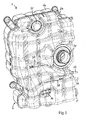
- FIG. 1 An expansion tank 1 according to an embodiment of the present invention is illustrated in Figs 1-6 .
- This expansion tank 1 is intended to be included in a cooling system of a motor vehicle, for instance a cooling system 40 of the type illustrated in Fig 7 .
- the expansion tank 1 comprises an outer casing 2 of rigid material, for instance plastic, and an expansion chamber 3 (see Figs 4 and 6 ) provided inside the casing.
- the expansion chamber 3 is separated from the surroundings by the casing 2 and comprises a lower part 3a, in which coolant is to be accumulated, and an upper part 3b, in which air is to be accumulated.
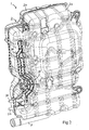
- the casing 2 is formed by a rear piece 2a and a front piece 2b, which are secured to each other by hot plate welding or in any other suitable manner.
- the casing 2 is provided with an outlet opening 4 (see Figs 3 , 4 and 6 ) which is intended to be connected to a coolant conduit of a cooling system in order to allow exchange of coolant between the expansion chamber 3 and other parts of the cooling system via this outlet opening 4.
- the outlet opening 4 is located at the bottom of the expansion chamber 3.
- a pipe 5 connected to the outlet opening 4 protrudes from the underside of the casing 2. Said coolant conduit is intended to be connected to this pipe 5.
- the casing 2 is provided with a first inlet opening 6 which is intended to be connected to a vent conduit of said cooling system in order to allow coolant and air to flow into the upper part 3b of the expansion chamber 3 via this first inlet opening 6.
- a first inlet basin 7 and a settling basin 8 are arranged in the upper part 3b of the expansion chamber 3.
- the first inlet basin 7 is configured to receive the coolant which flows into the expansion chamber 3 via the first inlet opening 6, wherein this coolant may be temporarily accumulated in the first inlet basin 7 before passing on towards the settling basin 8.
- the first inlet basin 7 is connected to the settling basin 8 by a flow passage 9, via which coolant accumulated in the first inlet basin 7 may flow from an upper part of the first inlet basin 7 and down into the settling basin 8.
- the settling basin 8 is configured to receive the coolant which flows from the inlet basin 7 via the flow passage 9, wherein this coolant may be temporarily accumulated in the settling basin 8 before passing further on towards the lower part 3a of the expansion chamber.
- the settling basin 8 is provided with an outlet 10, via which coolant accumulated in the settling basin 8 may flow from an upper part of settling basin and out of the settling basin. Particulate contaminants contained in the coolant accumulated in the settling basin 8 is allowed to settle at the bottom of the settling basin under the effect of gravity.
- the settling basin 8 extends between a first wall 11 located at an inlet end of the settling basin 8 and a second wall 12 located opposite said first wall 11 at an outlet end of the settling basin 8. Coolant enters the settling basin 8 via an inlet at said inlet end and leaves the settling basin via the outlet 10 at said outlet end.
- the inlet of the settling basin 8 has an inlet edge 14 provided on said first wall 11, wherein the coolant flows over this inlet edge 14 when entering the settling basin 8.
- the outlet 10 of the settling basin 8 has an outlet edge 15 provided on said second wall 12, wherein the coolant flows over this outlet edge 15 when leaving the settling basin 8.
- the inlet edge 14 is located at a higher elevation in the expansion chamber 3 than the outlet edge 15 to thereby allow the coolant flowing over the inlet edge 14 to fall vertically down into the coolant previously accumulated in the settling basin 8.
- the above-mentioned flow passage 9 comprises a first guide member 16, which extends between the first inlet basin 7 and the settling basin 8 and along which the coolant flows when passing through the flow passage 9 from the first inlet basin 7 to the settling basin 8.
- the first guide member 16 is preferably flat and slopes downwards towards the settling basin 8 at an angle a (see Fig 4 ) of 5-15°, preferably 5-10°, in relation to the horizontal plane.
- a see Fig 4
- the upper end of the first guide member 16 is connected to an upper end of a curved wall 17 of the first inlet basin 7, whereas the lower end of the first guide member 16 is connected to the above-mentioned first wall 11 of the settling basin 8.
- the upper end of said curved wall 17 forms an upper edge 18 (see Figs 4 and 6 ) of the first inlet basin 7 and the first inlet opening 6 is provided in the first inlet basin 7 at a level below this upper edge 18 so that the coolant flowing into the expansion chamber 3 via the first inlet opening 6 will rise upwards in the first inlet basin 7 and then over to the first guide member 16 via this upper edge 18.
- a drain hole 19 is provided in a lower part of the first inlet basin 7 to thereby allow coolant accumulated in the first inlet basin 7 to be drained off from the first inlet basin via this drain hole 19 when the flow of coolant into the expansion chamber 3 via the first inlet opening 6 has stopped.
- the casing 2 is also provided with a second inlet opening 20 which is intended to be connected to a vent conduit of said cooling system in order to allow coolant and air to flow into the upper part 3b of the expansion chamber 3 via this second inlet opening 20.
- the flow of coolant into the expansion chamber 3 via the first inlet opening 6 is intended to be lower than the flow of coolant into the expansion chamber 3 via the second inlet opening 20 and the cross-sectional area of the first inlet opening 6 is therefore preferably smaller than the cross-sectional area of the second inlet opening 20.
- a second inlet basin 21 is arranged in the upper part 3b of the expansion chamber 3.
- the second inlet basin 21 is configured to receive the coolant which flows into the expansion chamber 3 via the second inlet opening 20, wherein this coolant may be temporarily accumulated in the second inlet basin 21 before passing on towards the lower part 3a of the expansion chamber. Coolant entering the expansion chamber 3 via the second inlet opening 20 is directed to the lower part 3a of the expansion chamber without passing the first inlet basin 7, the first guide member 16 and the settling basin 8.
- a second guide member 22 is connected to the second inlet basin 21, wherein coolant accumulated in the second inlet basin 21 may flow from an upper part of the second inlet basin 21 and further on towards the lower part 3a of the expansion chamber 3 via this second guide member 22.
- the second guide member 22 is arranged below the first guide member 16 and the settling basin 8.
- the second guide member 22 is undulated and has a crest 23 which extends perpendicularly to the longitudinal direction of the second guide member 22.
- An upper end of the second guide member 22 is connected to an upper end of a curved wall 24 of the second inlet basin 21.
- the upper end of said curved wall 24 forms an upper edge 25 (see Figs 4 and 6 ) of the second inlet basin 21 and the second inlet opening 20 is provided in the second inlet basin 21 at a level below this upper edge 25 so that the coolant flowing into the expansion chamber 3 via the second inlet opening 20 will rise upwards in the second inlet basin 21 and then over to the second guide member 22 via this upper edge 25.
- the top of the crest 23 is located at a slightly lower elevation in the expansion chamber 3 than the upper edge 25 of the second inlet basin 21.
- a wave trough 26 is formed between the upper edge 25 of the second inlet basin 21 and the crest 23, wherein coolant flowing along the second guide member 22 will be temporarily accumulated in this wave trough 26 before flowing over the top of the crest 23.
- the settling basin 8 is connected to the second guide member 22 by a flow passage 27, via which coolant may flow from the outlet 10 of the settling basin 8 and fall down onto the second guide member 22.
- a third guide member 28 is arranged in the expansion chamber 3 below the second guide member 22.
- This third guide member 28 slopes downwards from an upper end 28b located in the upper part 3b of the expansion chamber 3 to a lower end 28a located in the lower part 3a of the expansion chamber.
- the second guide member 22 is connected to the third guide member 28 by a flow passage 29, via which coolant may flow from the lower end 22a of the second guide member 22 and fall down onto the third guide member 28.
- a drain hole 37 is provided in a lower part of the second inlet basin 21 to thereby allow coolant accumulated in the second inlet basin 21 to be drained off from the second inlet basin via this drain hole 37 when the flow of coolant into the expansion chamber 3 via the second inlet opening 20 has stopped.
- a pipe socket 32 connected to the first inlet opening 6 and another pipe socket 33 connected to the second inlet opening 20 protrude from a side wall of the casing 2.
- Each pipe socket 32, 33 is connected to the associated inlet opening 6, 20 via an inlet conduit 34, 35 provided on the outside of the casing 2, as illustrated in Fig 2 .
- the above-mentioned vent conduits are intended to be connected to these pipe sockets 32, 33.
- the expansion tank 1 is provided with a closable refill opening 34 (see Fig 1 ) which is arranged on the casing 2. Coolant may be introduced into the expansion chamber 3 via this refill opening 34 in order to provide for replenishment of the cooling system.
- This refill opening 34 is closed by means of a removable lid (not shown).
- the expansion tank 1 is provided with a valve device 35 which is mounted to the casing 2 and comprises a pressure relief valve for limiting the pressure in the expansion chamber 3 and a return valve.
- the pressure relief valve allows air and vapor to flow out from the upper part 3b of the expansion chamber 3 when the pressure in the expansion chamber, due to an increase of the coolant volume, exceeds a pressure level given by the pressure relief valve.
- the pressure relief valve ensures that the pressure in the expansion chamber 3 cannot exceed a predetermined pressure level.
- the return valve allows air to flow into the upper part 3b of the expansion chamber 3 from the surroundings when the pressure in the expansion chamber, due to a reduction of the coolant volume, becomes lower than a pressure level given by the return valve.
- the expansion tank 1 is also provided with a liquid level sensor 36 (see Fig 1 ) which is mounted to the casing 2 at a lower part thereof and configured to give off a signal when the coolant level in the expansion chamber 3 has reached a given lower level.
- a liquid level sensor 36 (see Fig 1 ) which is mounted to the casing 2 at a lower part thereof and configured to give off a signal when the coolant level in the expansion chamber 3 has reached a given lower level.
- the casing 2 is provided with a marking 38 (see Fig 1 ) which indicates the minimum coolant level in the expansion chamber 3 and another marking 39 which indicates the maximum coolant level in the expansion chamber 3.
- a closable discharge opening may be provided at the bottom of the settling basin 8 in order to make possible a discharge of particulate contaminants settled at the bottom of the settling basin.
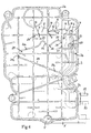
- Fig 6 illustrates the flow of coolant through the expansion chamber 3. Coolant and accompanying air bubbles are led into the first inlet basin 7 from a first vent conduit via the first inlet opening 6. From the first inlet basin 7 the coolant runs over to the first guide member 16 via the upper edge 18 of the first inlet basin. By means of the first inlet basin 7 it is ensured that the coolant will flow along the first guide member 16 in a well-distributed flow so that a thin layer of coolant is formed on the first guide member 16. From the lower end of the first guide member 16 the coolant runs over the inlet edge 14 and down into the settling basin 8. Particulate contaminants contained in the coolant received in the settling basin 8 settle at the bottom of the settling basin 8 under the effect of gravity. Coolant leaving the settling basin 8 will run over the outlet edge 15 and down onto the second guide member 22 via the flow passage 27.
- Coolant and accompanying air bubbles are led into the second inlet basin 21 from a second vent conduit via the second inlet opening 20. From the second inlet basin 21 the coolant runs over to the second guide member 22 via the upper edge 25 of the second inlet basin 21. By means of the second inlet basin 21 it is ensured that the coolant will flow over the upper end of the second guide member 22 in a well-distributed flow so that a thin layer of coolant is formed on the upper end of the second guide member 22. The coolant then runs down into the wave trough 26 on the second guide member 22 and will thereafter pass over the top of the crest 23 on the second guide member 22.
- the wave trough 26 By means of the wave trough 26 it is ensured that the coolant will flow over the top of the crest 23 in a well-distributed flow so that a thin layer of coolant is formed on the top of the crest 23.
- the coolant flowing along the second guide member 22 will join the coolant which falls down onto the second guide member 22 from the flow passage 27.
- the combined coolant flow is then directed to the lower part 3a of the expansion chamber 3 via the third guide member 28 and mixed with the coolant accumulated in the lower part 3a of the expansion chamber. Coolant leaves the expansion chamber 3 via the outlet 4 at the bottom of the expansion chamber.
- a cooling system 40 intended for a motor vehicle is schematically illustrated in Fig 7 .
- This cooling system 40 comprises a cooling circuit 41 for cooling a combustion engine 42 of the vehicle by means of a coolant flowing through the cooling circuit.
- the coolant is preferably in the form of water, with possible antifreezing additives such as for instance glycol.
- a coolant pump 43 is provided in the cooling circuit 41 in order to circulate the coolant in the cooling circuit.
- a radiator 44 for instance in the form of a conventional coolant radiator, is provided in the cooling circuit 41 in order to cool the coolant.
- This radiator 44 has a coolant inlet 45a which is connected to a coolant outlet 46b of the combustion engine 42 via a first conduit 47 of the cooling circuit, and a coolant outlet 45b which is connected to a coolant inlet 46a of the combustion engine 42 via a second conduit 48 of the cooling circuit.
- the coolant pump 43 is arranged in the second conduit 48.
- the first conduit 47 is connected to the second conduit 48 via a third conduit 49 of the cooling circuit.
- This third conduit 49 is configured to allow coolant to be returned from the coolant outlet 46b of the combustion engine 42 back to the coolant inlet 46a of the combustion engine without passing through the radiator 44.
- the third conduit 49 constitutes a bypass conduit, via which coolant circulating in the cooling circuit 41 can bypass the radiator 44 on its way between the coolant outlet 46b and the coolant inlet 46a of the combustion engine 42. Between the coolant inlet 46a and the coolant outlet 46b of the combustion engine 42, the coolant is circulated through coolant ducts (not shown) inside the combustion engine while absorbing heat from the combustion engine.
- a thermostat 50 is provided at the junction point between the first conduit 47 and the third conduit 49.
- the thermostat 50 will either direct the coolant from the combustion engine 42 to the radiator 44 in order to allow the coolant to be cooled therein before being returned to the combustion engine 42, or direct the coolant from the combustion engine 42 directly back to the combustion engine via the third conduit 49 without passing through the radiator 44.
- the coolant flowing through the radiator 44 is cooled by means of air which is blown towards the radiator when the motor vehicle is in motion.
- the cooling system 40 may also comprise a fan (not shown) for generating an air flow through the radiator 44. This fan may be connected to the combustion engine 42 in order to be driven by the combustion engine.
- the cooling system 40 is provided with an expansion tank 1 of the type described above.
- the outlet opening 4 of the expansion tank 1 is connected to the above-mentioned second conduit 48 via a fourth conduit 51 of the cooling circuit 41.
- This fourth conduit 51 is connected to the second conduit 48 at a point located between the radiator 44 and the coolant pump 43.
- the first inlet opening 6 of the expansion tank 1 is connected to the radiator 44 via a first vent conduit 52 in order to allow coolant and air to flow from the radiator 44 and into the upper part 3b of the expansion chamber 3 via this first vent conduit 52 and the first inlet opening 6 of the expansion tank 1.
- the second inlet opening 20 is connected to cooling ducts in the combustion engine 42 via a second vent conduit 53 in order to allow coolant and air to flow from the combustion engine 42 and into the upper part 3b of the expansion chamber 3 via this second vent conduit 53 and the second inlet opening 20 of the expansion tank 1.
- the diameter of the first vent conduit 52 is preferably smaller than the diameter of the second vent conduit 53.
- the mass flow of coolant through the first vent conduit 52 is with advantage considerably lower than the mass flow of coolant through the second vent conduit 53, for instance 25-50%, preferably about one third, of the mass flow of coolant through the second vent conduit 53. Coolant is led into the expansion chamber 3 of the expansion tank 1 via the vent conduits 52, 53 and is returned from the expansion chamber 3 to the cooling circuit 41 via the above-mentioned fourth conduit 51 after deaeration in the expansion chamber.
- the expansion tank according to the invention is particularly intended for use in a heavy motor vehicle, such as for instance a bus, a tractor truck or a lorry.
Landscapes
- Engineering & Computer Science (AREA)
- Chemical & Material Sciences (AREA)
- Combustion & Propulsion (AREA)
- Mechanical Engineering (AREA)
- General Engineering & Computer Science (AREA)
- Cooling, Air Intake And Gas Exhaust, And Fuel Tank Arrangements In Propulsion Units (AREA)
Abstract
- an expansion chamber (3) with a lower part (3a) for accumulation of coolant and an upper part (3b) for accumulation of air;
- an inlet opening (6) to be connected to a vent conduit of the cooling system;
- an inlet basin (7), which is arranged in said upper part (3b) of the expansion chamber and configured to receive the coolant which flows into the expansion chamber via said inlet opening; and
- a settling basin (8), which is arranged in said upper part (3b) of the expansion chamber and connected to the inlet basin, wherein particulate contaminants contained in the coolant received in the settling basin is allowed to settle at the bottom of the settling basin under the effect of gravity.
Description
- The present invention relates to an expansion tank according to the preamble of
claim 1 which is intended to be included in a cooling system of a motor vehicle. The invention also relates to a cooling system for a motor vehicle provided with such an expansion tank. - A combustion engine of a motor vehicle is cooled by means of coolant which is circulated in a cooling system. When the combustion engine is in operation it gives off heat to the coolant, which is thereby heated and expanded. The resulting total volume increase of the coolant in the vehicle's cooling system may amount to several litres and depends on the original coolant volume and the temperature increase. In order to prevent the pressure from increasing too much in the cooling system, the cooling system is provided with an expansion tank which can accommodate the surplus coolant generated in connection with the expansion of the coolant. The boiling point of the coolant rises with increasing pressure, and it is therefore desirable to maintain a certain positive pressure in the cooling system when the engine is in operation to thereby prevent coolant boiling. To make this possible and at the same time prevent a dangerously high coolant pressure, the expansion tank is provided with a pressure relief valve which ensures that the pressure in the expansion tank cannot exceed a predetermined pressure level. When the coolant expands as a consequence of heating, the air in the expansion tank is compressed and the pressure in the expansion tank and in the rest of the cooling system is thereby increased.
- Another important function of an expansion tank of the above-mentioned type is that it should be possible for the coolant received in the expansion tank to be deaerated in the expansion tank before leaving the expansion tank. The air which has been absorbed by the coolant when circulating through the cooling circuit of the cooling system and which therefore accompanies the coolant to the expansion tank is intended to rise to the surface of the coolant volume received in the expansion tank in order to accumulate in an air-filled space at an upper part of the expansion tank. Hereby, the coolant in the expansion tank is deaerated.
- Some cast components included in a combustion engine of a motor vehicle have a very complex construction with narrow ducts and grooves and it is therefore difficult to completely clean such engine components from all foundry sand particles and metallic particles. Such remaining particles and other particulate contaminants may be mixed with the coolant when the coolant flows through the coolant ducts in the combustion engine and through other parts of the cooling system. Narrow ducts in different components included in the cooling circuit of the cooling system, such as for instance ducts in heat exchangers, valves or thermostats, may become clogged by particulate contaminants flowing through the cooling circuit together with the coolant. Such clogging may damage the components and/or impair the functioning thereof. Furthermore, the particulate contaminants may cause increased wear of the components included in the cooling circuit. It is previously known to catch such particulate contaminants by means of a particulate filter arranged in the combustion engine. However, a disadvantage with such a particulate filter is that it may become clogged and therefore requires recurrent maintenance.
- The object of the present invention is to achieve a new and advantageous manner of removing particulate contaminants from coolant circulating through a cooling circuit of a cooling system.
- According to the present invention, the above-mentioned object is achieved by an expansion tank having the features defined in
claim 1. - The expansion tank of the present invention comprises:
- an outer casing;
- an expansion chamber enclosed within the casing, wherein the expansion chamber comprises a lower part, in which coolant is to be accumulated, and an upper part, in which air is to be accumulated;
- an inlet opening, here denominated first inlet opening, which is arranged in the casing and intended to be connected to a vent conduit of said cooling system in order to allow coolant and air to flow into said upper part of the expansion chamber via this first inlet opening;
- an outlet opening which is arranged in the casing and intended to be connected to a coolant conduit of said cooling system in order to allow coolant to flow out of said lower part of the expansion chamber via this outlet opening;
- an inlet basin, here denominated first inlet basin, which is arranged in said upper part of the expansion chamber; and
- a settling basin arranged in said upper part of the expansion chamber.
- The first inlet basin is configured to receive the coolant which flows into the expansion chamber via said first inlet opening. The first inlet basin is connected to the settling basin by a flow passage, via which coolant may flow from an upper part of the first inlet basin and down into the settling basin, wherein particulate contaminants contained in the coolant received in the settling basin is allowed to settle at the bottom of the settling basin under the effect of gravity. The settling basin is provided with an outlet, via which coolant may flow from an upper part of settling basin and further on towards said lower part of the expansion chamber.
- The coolant flowing into the expansion tank via the first inlet opening is initially accumulated and spread out in the first inlet basin before flowing from an upper part of the first inlet basin and down into the settling basin. Particulate contaminants contained in the coolant entering the expansion chamber via the first inlet opening cannot settle in the first inlet basin due to the fact that the flow of coolant in the first inlet basin is too turbulent. However, the flow of coolant in the settling basin is sufficiently calm to enable a settling of particulate contaminants at the bottom of the settling basin under the effect of gravity. Thus, with the solution according to the present invention, particulate contaminants may be removed from the coolant in a simple and cost-efficient manner without having to use any particulate filter that may become clogged.
- According to an embodiment of the invention, the flow passage between the first inlet basin and the settling basin comprises a guide member, here denominated first guide member, which extends between the first inlet basin and the settling basin and along which the coolant is to flow when passing from the first inlet basin to the settling basin, wherein this guide member slopes downwards towards the settling basin. The coolant flowing into the expansion chamber via the first inlet opening is subjected to an initial deaeration in the first inlet basin in that air bubbles rise to the surface of the coolant accumulated in the inlet basin and join the air in the air-filled upper part of the expansion chamber. The coolant is then subjected to a further deaeration when flowing over the first guide member. With a suitable dimensioning of the first inlet basin and the first guide member in relation to the flow of coolant through the first inlet opening, the layer of coolant formed on the first guide member will be so thin that the air bubbles accompanying the coolant flowing along the first guide member very easily can join the air above the first guide member. The coolant is thereafter subjected to a further deaeration in the settling basin in that air bubbles rise to the surface of the coolant accumulated in the settling basin and join the air in the air-filled upper part of the expansion chamber. By making the coolant pass the first inlet basin, the first guide member and the settling basin, it will be possible to achieve an efficient deaeration of the coolant in a space-saving manner before it is accumulated in the lower part of the expansion chamber, where it is subjected to a final deaeration before leaving the expansion chamber.
- According to another embodiment of the invention, the first guide member is flat and slopes downwards towards the settling basin at an angle of 5-15°, preferably 5-10°, in relation to the horizontal plane. Hereby, the first guide member slopes gently downwards and the flow velocity of the coolant along the first guide member is thereby limited, which is advantageous with respect to the deaeration.
- Another embodiment of the invention is characterized in:
- that the settling basin extends between a first wall located at an inlet end of the settling basin and a second wall located at an outlet end of the settling basin;
- that the outlet of the settling basin has an outlet edge provided on said second wall; and
- that the settling basin comprises an inlet having an inlet edge provided on said first wall, wherein the inlet edge is located at a higher elevation in the expansion chamber than the outlet edge to thereby allow the coolant flowing over the inlet edge to fall vertically down into the settling basin. By falling vertically down into the settling basin, the coolant entering the settling basin is prevented from "sliding" directly from the inlet end to the outlet end of the settling basin at the upper surface of the coolant previously accumulated in the settling basin, and it is thereby ensured that the coolant entering the settling basin will get mixed with the coolant previously accumulated in the settling basin and remain in the settling basin for a period of time that is sufficient with respect to the settling process.
- According to another embodiment of the invention, a second inlet opening is arranged in the casing and intended to be connected to a vent conduit of said cooling system in order to allow coolant and air to flow into the expansion chamber via this second inlet opening, wherein the expansion tank is so configured that the coolant entering the expansion chamber via the second inlet opening is allowed to flow to said lower part of the expansion chamber without passing the first inlet basin and the settling basin. Hereby, only a part of the total vent flow will pass the first inlet basin and the settling basin, which will make it possible to obtain a reduced coolant flow through the settling basin and thereby favourable settling conditions for the particulate contaminants.
- Another embodiment of the invention is characterized in:
- that a second inlet basin is arranged in said upper part of the expansion chamber, wherein this second inlet basin is configured to receive the coolant which flows into the expansion chamber via said second inlet opening; and
- that a second guide member is connected to the second inlet basin, wherein coolant may flow from an upper part of the second inlet basin and further on towards said lower part of the expansion chamber via this second guide member.
- Hereby, the coolant flowing into the expansion chamber via the second inlet opening is subjected to an initial deaeration in the second inlet basin in that air bubbles rise to the surface of the coolant accumulated in the second inlet basin and join the air in the air-filled upper part of the expansion chamber. The coolant is then subjected to a further deaeration when flowing over the second guide member. By making the coolant pass the second inlet basin and the second guide member, it will be possible to achieve an efficient deaeration of the coolant in a space-saving manner before it is accumulated in the lower part of the expansion chamber, where it is subjected to a final deaeration before leaving the expansion chamber.
- According to another embodiment of the invention, the second guide member is undulated and has at least one crest which extends perpendicularly to the longitudinal direction of the second guide member. With a suitable dimensioning of the second inlet basin and the second guide member in relation to the flow of coolant through the second inlet opening, the layer of coolant formed on the crest of the second guide member will be so thin that the air bubbles accompanying the coolant flowing over this crest very easily can join the air above the second guide member.
- Another embodiment of the invention is characterized in:
- that a third guide member is arranged in the expansion chamber below the second guide member, wherein this third guide member slopes downwards from an upper end located in said upper part of the expansion chamber to a lower end located in said lower part of the expansion chamber; and
- that the second guide member is connected to the third guide member by a flow passage, via which coolant may flow from a lower end of the second guide member and fall down onto the third guide member.
- Thus, the coolant which flows into the upper part of the expansion chamber via the first and second inlet openings will be directed by the third guide member down into the coolant accumulated in the lower part of the expansion chamber and may thereby slide down into the coolant accumulated in the lower part of the expansion chamber in a rather gentle manner. Hereby, only a very small amount of air will be drawn down into the coolant accumulated in the lower part of the expansion chamber when the coolant from the upper part of the expansion chamber enters the coolant accumulated in the lower part of the expansion chamber.
- Further advantageous features of the expansion tank of the present invention will appear from the following description and the dependent claims.
- The invention also relates to a cooling system having the features defined in
claim 12. - Further advantageous features of the cooling system of the present invention will appear from the following description and the dependent claims.
- With reference to the appended drawings, a specific description of preferred embodiments of the invention cited as examples follows below. In the drawings:
- Fig 1
- is a perspective view from the front of an expansion tank according to an embodiment of the present invention,
- Fig 2
- is a perspective view from behind of the expansion tank of
Fig 1 , - Fig 3
- is a perspective view of a rear piece which forms part of the expansion tank of
Fig 1 , - Fig 4
- is a front view of the rear piece of
Fig 3 , - Fig 5
- is a perspective view of a front piece which forms part of the expansion tank of
Fig 1 , - Fig 6
- is a schematic front view of the rear piece of
Fig 3 , and - Fig 7
- is an outline diagram of a cooling system comprising an expansion tank according to the present invention.
- An
expansion tank 1 according to an embodiment of the present invention is illustrated inFigs 1-6 . Thisexpansion tank 1 is intended to be included in a cooling system of a motor vehicle, for instance acooling system 40 of the type illustrated inFig 7 . Theexpansion tank 1 comprises anouter casing 2 of rigid material, for instance plastic, and an expansion chamber 3 (seeFigs 4 and6 ) provided inside the casing. The expansion chamber 3 is separated from the surroundings by thecasing 2 and comprises a lower part 3a, in which coolant is to be accumulated, and anupper part 3b, in which air is to be accumulated. - In the illustrated example, the
casing 2 is formed by a rear piece 2a and afront piece 2b, which are secured to each other by hot plate welding or in any other suitable manner. - The
casing 2 is provided with an outlet opening 4 (seeFigs 3 ,4 and6 ) which is intended to be connected to a coolant conduit of a cooling system in order to allow exchange of coolant between the expansion chamber 3 and other parts of the cooling system via thisoutlet opening 4. Theoutlet opening 4 is located at the bottom of the expansion chamber 3. Apipe 5 connected to theoutlet opening 4 protrudes from the underside of thecasing 2. Said coolant conduit is intended to be connected to thispipe 5. - The
casing 2 is provided with a first inlet opening 6 which is intended to be connected to a vent conduit of said cooling system in order to allow coolant and air to flow into theupper part 3b of the expansion chamber 3 via thisfirst inlet opening 6. Afirst inlet basin 7 and asettling basin 8 are arranged in theupper part 3b of the expansion chamber 3. Thefirst inlet basin 7 is configured to receive the coolant which flows into the expansion chamber 3 via thefirst inlet opening 6, wherein this coolant may be temporarily accumulated in thefirst inlet basin 7 before passing on towards the settlingbasin 8. Thefirst inlet basin 7 is connected to thesettling basin 8 by aflow passage 9, via which coolant accumulated in thefirst inlet basin 7 may flow from an upper part of thefirst inlet basin 7 and down into the settlingbasin 8. The settlingbasin 8 is configured to receive the coolant which flows from theinlet basin 7 via theflow passage 9, wherein this coolant may be temporarily accumulated in thesettling basin 8 before passing further on towards the lower part 3a of the expansion chamber. The settlingbasin 8 is provided with anoutlet 10, via which coolant accumulated in thesettling basin 8 may flow from an upper part of settling basin and out of the settling basin. Particulate contaminants contained in the coolant accumulated in thesettling basin 8 is allowed to settle at the bottom of the settling basin under the effect of gravity. - The settling
basin 8 extends between afirst wall 11 located at an inlet end of the settlingbasin 8 and asecond wall 12 located opposite saidfirst wall 11 at an outlet end of the settlingbasin 8. Coolant enters the settlingbasin 8 via an inlet at said inlet end and leaves the settling basin via theoutlet 10 at said outlet end. The inlet of the settlingbasin 8 has aninlet edge 14 provided on saidfirst wall 11, wherein the coolant flows over thisinlet edge 14 when entering the settlingbasin 8. Theoutlet 10 of the settlingbasin 8 has anoutlet edge 15 provided on saidsecond wall 12, wherein the coolant flows over thisoutlet edge 15 when leaving the settlingbasin 8. Theinlet edge 14 is located at a higher elevation in the expansion chamber 3 than theoutlet edge 15 to thereby allow the coolant flowing over theinlet edge 14 to fall vertically down into the coolant previously accumulated in thesettling basin 8. - The above-mentioned
flow passage 9 comprises afirst guide member 16, which extends between thefirst inlet basin 7 and the settlingbasin 8 and along which the coolant flows when passing through theflow passage 9 from thefirst inlet basin 7 to thesettling basin 8. Thefirst guide member 16 is preferably flat and slopes downwards towards the settlingbasin 8 at an angle a (seeFig 4 ) of 5-15°, preferably 5-10°, in relation to the horizontal plane. In the illustrated example, the upper end of thefirst guide member 16 is connected to an upper end of acurved wall 17 of thefirst inlet basin 7, whereas the lower end of thefirst guide member 16 is connected to the above-mentionedfirst wall 11 of the settlingbasin 8. The upper end of saidcurved wall 17 forms an upper edge 18 (seeFigs 4 and6 ) of thefirst inlet basin 7 and thefirst inlet opening 6 is provided in thefirst inlet basin 7 at a level below thisupper edge 18 so that the coolant flowing into the expansion chamber 3 via thefirst inlet opening 6 will rise upwards in thefirst inlet basin 7 and then over to thefirst guide member 16 via thisupper edge 18. - A
drain hole 19 is provided in a lower part of thefirst inlet basin 7 to thereby allow coolant accumulated in thefirst inlet basin 7 to be drained off from the first inlet basin via thisdrain hole 19 when the flow of coolant into the expansion chamber 3 via thefirst inlet opening 6 has stopped. - In the illustrated embodiment, the
casing 2 is also provided with a second inlet opening 20 which is intended to be connected to a vent conduit of said cooling system in order to allow coolant and air to flow into theupper part 3b of the expansion chamber 3 via this second inlet opening 20. The flow of coolant into the expansion chamber 3 via thefirst inlet opening 6 is intended to be lower than the flow of coolant into the expansion chamber 3 via the second inlet opening 20 and the cross-sectional area of thefirst inlet opening 6 is therefore preferably smaller than the cross-sectional area of the second inlet opening 20. - A
second inlet basin 21 is arranged in theupper part 3b of the expansion chamber 3. Thesecond inlet basin 21 is configured to receive the coolant which flows into the expansion chamber 3 via the second inlet opening 20, wherein this coolant may be temporarily accumulated in thesecond inlet basin 21 before passing on towards the lower part 3a of the expansion chamber. Coolant entering the expansion chamber 3 via the second inlet opening 20 is directed to the lower part 3a of the expansion chamber without passing thefirst inlet basin 7, thefirst guide member 16 and the settlingbasin 8. - A
second guide member 22 is connected to thesecond inlet basin 21, wherein coolant accumulated in thesecond inlet basin 21 may flow from an upper part of thesecond inlet basin 21 and further on towards the lower part 3a of the expansion chamber 3 via thissecond guide member 22. Thesecond guide member 22 is arranged below thefirst guide member 16 and the settlingbasin 8. In the illustrated example, thesecond guide member 22 is undulated and has acrest 23 which extends perpendicularly to the longitudinal direction of thesecond guide member 22. An upper end of thesecond guide member 22 is connected to an upper end of acurved wall 24 of thesecond inlet basin 21. The upper end of saidcurved wall 24 forms an upper edge 25 (seeFigs 4 and6 ) of thesecond inlet basin 21 and the second inlet opening 20 is provided in thesecond inlet basin 21 at a level below thisupper edge 25 so that the coolant flowing into the expansion chamber 3 via the second inlet opening 20 will rise upwards in thesecond inlet basin 21 and then over to thesecond guide member 22 via thisupper edge 25. The top of thecrest 23 is located at a slightly lower elevation in the expansion chamber 3 than theupper edge 25 of thesecond inlet basin 21. Awave trough 26 is formed between theupper edge 25 of thesecond inlet basin 21 and thecrest 23, wherein coolant flowing along thesecond guide member 22 will be temporarily accumulated in thiswave trough 26 before flowing over the top of thecrest 23. - The settling
basin 8 is connected to thesecond guide member 22 by aflow passage 27, via which coolant may flow from theoutlet 10 of the settlingbasin 8 and fall down onto thesecond guide member 22. - In the illustrated embodiment, a
third guide member 28 is arranged in the expansion chamber 3 below thesecond guide member 22. Thisthird guide member 28 slopes downwards from an upper end 28b located in theupper part 3b of the expansion chamber 3 to alower end 28a located in the lower part 3a of the expansion chamber. Thesecond guide member 22 is connected to thethird guide member 28 by aflow passage 29, via which coolant may flow from thelower end 22a of thesecond guide member 22 and fall down onto thethird guide member 28. - A
drain hole 37 is provided in a lower part of thesecond inlet basin 21 to thereby allow coolant accumulated in thesecond inlet basin 21 to be drained off from the second inlet basin via thisdrain hole 37 when the flow of coolant into the expansion chamber 3 via the second inlet opening 20 has stopped. - In the illustrated example, a
pipe socket 32 connected to thefirst inlet opening 6 and anotherpipe socket 33 connected to the second inlet opening 20 protrude from a side wall of thecasing 2. Eachpipe socket inlet opening inlet conduit casing 2, as illustrated inFig 2 . The above-mentioned vent conduits are intended to be connected to thesepipe sockets - The
expansion tank 1 is provided with a closable refill opening 34 (seeFig 1 ) which is arranged on thecasing 2. Coolant may be introduced into the expansion chamber 3 via this refill opening 34 in order to provide for replenishment of the cooling system. This refill opening 34 is closed by means of a removable lid (not shown). - Furthermore, the
expansion tank 1 is provided with avalve device 35 which is mounted to thecasing 2 and comprises a pressure relief valve for limiting the pressure in the expansion chamber 3 and a return valve. The pressure relief valve allows air and vapor to flow out from theupper part 3b of the expansion chamber 3 when the pressure in the expansion chamber, due to an increase of the coolant volume, exceeds a pressure level given by the pressure relief valve. Thus, the pressure relief valve ensures that the pressure in the expansion chamber 3 cannot exceed a predetermined pressure level. The return valve allows air to flow into theupper part 3b of the expansion chamber 3 from the surroundings when the pressure in the expansion chamber, due to a reduction of the coolant volume, becomes lower than a pressure level given by the return valve. - In the illustrated embodiment, the
expansion tank 1 is also provided with a liquid level sensor 36 (seeFig 1 ) which is mounted to thecasing 2 at a lower part thereof and configured to give off a signal when the coolant level in the expansion chamber 3 has reached a given lower level. - The
casing 2 is provided with a marking 38 (seeFig 1 ) which indicates the minimum coolant level in the expansion chamber 3 and another marking 39 which indicates the maximum coolant level in the expansion chamber 3. - A closable discharge opening (not shown) may be provided at the bottom of the settling
basin 8 in order to make possible a discharge of particulate contaminants settled at the bottom of the settling basin. -
Fig 6 illustrates the flow of coolant through the expansion chamber 3. Coolant and accompanying air bubbles are led into thefirst inlet basin 7 from a first vent conduit via thefirst inlet opening 6. From thefirst inlet basin 7 the coolant runs over to thefirst guide member 16 via theupper edge 18 of the first inlet basin. By means of thefirst inlet basin 7 it is ensured that the coolant will flow along thefirst guide member 16 in a well-distributed flow so that a thin layer of coolant is formed on thefirst guide member 16. From the lower end of thefirst guide member 16 the coolant runs over theinlet edge 14 and down into the settlingbasin 8. Particulate contaminants contained in the coolant received in thesettling basin 8 settle at the bottom of the settlingbasin 8 under the effect of gravity. Coolant leaving the settlingbasin 8 will run over theoutlet edge 15 and down onto thesecond guide member 22 via theflow passage 27. - Coolant and accompanying air bubbles are led into the
second inlet basin 21 from a second vent conduit via the second inlet opening 20. From thesecond inlet basin 21 the coolant runs over to thesecond guide member 22 via theupper edge 25 of thesecond inlet basin 21. By means of thesecond inlet basin 21 it is ensured that the coolant will flow over the upper end of thesecond guide member 22 in a well-distributed flow so that a thin layer of coolant is formed on the upper end of thesecond guide member 22. The coolant then runs down into thewave trough 26 on thesecond guide member 22 and will thereafter pass over the top of thecrest 23 on thesecond guide member 22. By means of thewave trough 26 it is ensured that the coolant will flow over the top of thecrest 23 in a well-distributed flow so that a thin layer of coolant is formed on the top of thecrest 23. After having passed the top of thecrest 23 the coolant flowing along thesecond guide member 22 will join the coolant which falls down onto thesecond guide member 22 from theflow passage 27. The combined coolant flow is then directed to the lower part 3a of the expansion chamber 3 via thethird guide member 28 and mixed with the coolant accumulated in the lower part 3a of the expansion chamber. Coolant leaves the expansion chamber 3 via theoutlet 4 at the bottom of the expansion chamber. - A
cooling system 40 intended for a motor vehicle is schematically illustrated inFig 7 . Thiscooling system 40 comprises acooling circuit 41 for cooling acombustion engine 42 of the vehicle by means of a coolant flowing through the cooling circuit. The coolant is preferably in the form of water, with possible antifreezing additives such as for instance glycol. Acoolant pump 43 is provided in thecooling circuit 41 in order to circulate the coolant in the cooling circuit. Furthermore, aradiator 44, for instance in the form of a conventional coolant radiator, is provided in thecooling circuit 41 in order to cool the coolant. Thisradiator 44 has acoolant inlet 45a which is connected to acoolant outlet 46b of thecombustion engine 42 via afirst conduit 47 of the cooling circuit, and a coolant outlet 45b which is connected to a coolant inlet 46a of thecombustion engine 42 via asecond conduit 48 of the cooling circuit. In the illustrated example, thecoolant pump 43 is arranged in thesecond conduit 48. Thefirst conduit 47 is connected to thesecond conduit 48 via athird conduit 49 of the cooling circuit. Thisthird conduit 49 is configured to allow coolant to be returned from thecoolant outlet 46b of thecombustion engine 42 back to the coolant inlet 46a of the combustion engine without passing through theradiator 44. Thus, thethird conduit 49 constitutes a bypass conduit, via which coolant circulating in thecooling circuit 41 can bypass theradiator 44 on its way between thecoolant outlet 46b and the coolant inlet 46a of thecombustion engine 42. Between the coolant inlet 46a and thecoolant outlet 46b of thecombustion engine 42, the coolant is circulated through coolant ducts (not shown) inside the combustion engine while absorbing heat from the combustion engine. Athermostat 50 is provided at the junction point between thefirst conduit 47 and thethird conduit 49. Depending on the temperature of the coolant, thethermostat 50 will either direct the coolant from thecombustion engine 42 to theradiator 44 in order to allow the coolant to be cooled therein before being returned to thecombustion engine 42, or direct the coolant from thecombustion engine 42 directly back to the combustion engine via thethird conduit 49 without passing through theradiator 44. - The coolant flowing through the
radiator 44 is cooled by means of air which is blown towards the radiator when the motor vehicle is in motion. Thecooling system 40 may also comprise a fan (not shown) for generating an air flow through theradiator 44. This fan may be connected to thecombustion engine 42 in order to be driven by the combustion engine. - The
cooling system 40 is provided with anexpansion tank 1 of the type described above. Theoutlet opening 4 of theexpansion tank 1 is connected to the above-mentionedsecond conduit 48 via afourth conduit 51 of thecooling circuit 41. Thisfourth conduit 51 is connected to thesecond conduit 48 at a point located between theradiator 44 and thecoolant pump 43. The first inlet opening 6 of theexpansion tank 1 is connected to theradiator 44 via afirst vent conduit 52 in order to allow coolant and air to flow from theradiator 44 and into theupper part 3b of the expansion chamber 3 via thisfirst vent conduit 52 and the first inlet opening 6 of theexpansion tank 1. The second inlet opening 20 is connected to cooling ducts in thecombustion engine 42 via asecond vent conduit 53 in order to allow coolant and air to flow from thecombustion engine 42 and into theupper part 3b of the expansion chamber 3 via thissecond vent conduit 53 and the second inlet opening 20 of theexpansion tank 1. The diameter of thefirst vent conduit 52 is preferably smaller than the diameter of thesecond vent conduit 53. The mass flow of coolant through thefirst vent conduit 52 is with advantage considerably lower than the mass flow of coolant through thesecond vent conduit 53, for instance 25-50%, preferably about one third, of the mass flow of coolant through thesecond vent conduit 53. Coolant is led into the expansion chamber 3 of theexpansion tank 1 via thevent conduits cooling circuit 41 via the above-mentionedfourth conduit 51 after deaeration in the expansion chamber. - The expansion tank according to the invention is particularly intended for use in a heavy motor vehicle, such as for instance a bus, a tractor truck or a lorry.
- The invention is of course not in any way restricted to the embodiments described above. On the contrary, many possibilities to modifications thereof will be apparent to a person with ordinary skill in the art without departing from the basic idea of the invention such as defined in the appended claims.
Claims (15)
- An expansion tank intended to be included in a cooling system of a motor vehicle in order to receive coolant which circulates in the cooling system, the expansion tank (1) comprising:- an outer casing (2);- an expansion chamber (3) enclosed within the casing (2), wherein the expansion chamber (3) comprises a lower part (3a), in which coolant is to be accumulated, and an upper part (3b), in which air is to be accumulated;- an inlet opening (6), here denominated first inlet opening, which is arranged in the casing (2) and intended to be connected to a vent conduit of said cooling system in order to allow coolant and air to flow into said upper part (3b) of the expansion chamber (3) via this first inlet opening (6); and- an outlet opening (4) which is arranged in the casing (2) and intended to be connected to a coolant conduit of said cooling system in order to allow coolant to flow out of said lower part (3a) of the expansion chamber (3) via this outlet opening (4);characterized in:- that an inlet basin (7), here denominated first inlet basin, is arranged in said upper part (3b) of the expansion chamber (3), wherein this inlet basin (7) is configured to receive the coolant which flows into the expansion chamber (3) via said first inlet opening (6);- that a settling basin (8) is arranged in said upper part (3b) of the expansion chamber (3);- that the first inlet basin (7) is connected to the settling basin (8) by a flow passage (9), via which coolant may flow from an upper part of the first inlet basin (7) and down into the settling basin (8), wherein particulate contaminants contained in the coolant received in the settling basin (8) is allowed to settle at the bottom of the settling basin under the effect of gravity; and- that the settling basin (8) is provided with an outlet (10), via which coolant may flow from an upper part of settling basin (8) and further on towards said lower part (3a) of the expansion chamber (3).
- An expansion tank according to claim 1, characterized in that said flow passage (9) comprises a guide member (16), here denominated first guide member, which extends between the first inlet basin (7) and the settling basin (8) and along which the coolant is to flow when passing from the first inlet basin (7) to the settling basin (8), wherein this guide member (16) slopes downwards towards the settling basin (8).
- An expansion tank according to claim 2, characterized in that the first guide member (16) is flat and slopes downwards towards the settling basin (8) at an angle (α) of 5-15°, preferably 5-10 °, in relation to the horizontal plane.
- An expansion tank according to any of claims 1-3, characterized in:- that the settling basin (8) extends between a first wall (11) located at an inlet end of the settling basin (8) and a second wall (12) located at an outlet end of the settling basin (8);- that the outlet (10) of the settling basin (8) has an outlet edge (15) provided on said second wall (12); and- that the settling basin (8) comprises an inlet having an inlet edge (14) provided on said first wall (11), wherein the inlet edge (14) is located at a higher elevation in the expansion chamber (3) than the outlet edge (15) to thereby allow the coolant flowing over the inlet edge (14) to fall vertically down into the settling basin (8).
- An expansion tank according to any of claims 1-4, characterized in that a second inlet opening (20) is arranged in the casing (2) and intended to be connected to a vent conduit of said cooling system in order to allow coolant and air to flow into the expansion chamber (3) via this second inlet opening (20), wherein the expansion tank (1) is so configured that the coolant entering the expansion chamber (3) via the second inlet opening (20) is allowed to flow to said lower part (3a) of the expansion chamber without passing the first inlet basin (7) and the settling basin (8).
- An expansion tank according to claim 5, characterized in that the cross-sectional area of the first inlet opening (6) is smaller than the cross-sectional area of the second inlet opening (20).
- An expansion tank according to claim 5 or 6, characterized in:- that a second inlet basin (21) is arranged in said upper part (3b) of the expansion chamber (3), wherein this second inlet basin (21) is configured to receive the coolant which flows into the expansion chamber (3) via said second inlet opening (20); and- that a second guide member (22) is connected to the second inlet basin (21), wherein coolant may flow from an upper part of the second inlet basin (21) and further on towards said lower part of the expansion chamber (3) via this second guide member (22).
- An expansion tank according to claim 7, characterized in that the second guide member (22) is undulated and has at least one crest (23) which extends perpendicularly to the longitudinal direction of the second guide member (22).
- An expansion tank according to claim 7 or 8, characterized in that the second guide member (22) is arranged below the settling basin (8).
- An expansion tank according to claim 9, characterized in that the settling basin (8) is connected to the second guide member (22) by a flow passage (27), via which coolant may flow from the outlet (10) of the settling basin (8) and fall down onto the second guide member (22).
- An expansion tank according to any of claims 7-10, characterized in:- that a third guide member (28) is arranged in the expansion chamber (3) below the second guide member (22), wherein this third guide member (28) slopes downwards from an upper end (28b) located in said upper part (3b) of the expansion chamber (3) to a lower end (28a) located in said lower part (3a) of the expansion chamber; and- that the second guide member (22) is connected to the third guide member (28) by a flow passage (29), via which coolant may flow from a lower end (22a) of the second guide member (22) and fall down onto the third guide member (28).
- A cooling system for a motor vehicle comprising:- a cooling circuit (41) for cooling a combustion engine (42) of the motor vehicle by means of coolant circulating in the cooling circuit (41); and- a radiator (44) provided in the cooling circuit (41) for cooling the coolant;characterized in that the cooling system (40) comprises an expansion tank (3) according to any of claims 1-11, wherein the first inlet opening (6) of the expansion tank (3) is connected to a vent conduit (52) included in the cooling circuit (41) and the outlet opening (4) of the expansion tank (3) is connected to a coolant conduit (51) included in the cooling circuit (41).
- A cooling system according to claim 12, characterized in that the expansion tank (3) is an expansion tank according to any of claims 5-11, wherein the first inlet opening (6) of the expansion tank (3) is connected to a first vent conduit (52) included in the cooling circuit (41) and the second inlet opening (20) of the expansion tank (3) is connected to a second vent conduit (53) included in the cooling circuit (41).
- A cooling system according to claim 13, characterized in that the diameter of said first vent conduit (52) is smaller than the diameter of said second vent conduit (53).
- A cooling system according to claim 13 or 14, characterized in:- that said first vent conduit (52) is connected to the radiator (44) in order to allow coolant and air to flow from the radiator (44) and into said upper part (3b) of the expansion chamber (3) via this first vent conduit (52) and the first inlet opening (6) of the expansion tank (3); and- that said second vent conduit (53) is connected to the combustion engine (42) in order to allow coolant and air to flow from the combustion engine (42) and into said upper part (3b) of the expansion chamber (3) via this second vent conduit (53) and the second inlet opening (20) of the expansion tank (3).
Applications Claiming Priority (1)
| Application Number | Priority Date | Filing Date | Title |
|---|---|---|---|
| SE1451253A SE539416C2 (en) | 2014-10-21 | 2014-10-21 | Expansion tank and cooling system including such an expansion tank |
Publications (2)
| Publication Number | Publication Date |
|---|---|
| EP3012429A1 true EP3012429A1 (en) | 2016-04-27 |
| EP3012429B1 EP3012429B1 (en) | 2019-07-17 |
Family
ID=54337146
Family Applications (1)
| Application Number | Title | Priority Date | Filing Date |
|---|---|---|---|
| EP15190338.2A Active EP3012429B1 (en) | 2014-10-21 | 2015-10-19 | Expansion tank and cooling system comprising such an expansion tank |
Country Status (2)
| Country | Link |
|---|---|
| EP (1) | EP3012429B1 (en) |
| SE (1) | SE539416C2 (en) |
Cited By (6)
| Publication number | Priority date | Publication date | Assignee | Title |
|---|---|---|---|---|
| WO2017209145A1 (en) * | 2016-06-02 | 2017-12-07 | 日立建機株式会社 | Expansion tank |
| DE102017120056A1 (en) * | 2017-08-31 | 2019-02-28 | Volkswagen Aktiengesellschaft | Expansion tank for a cooling system of a vehicle and vehicle with such a reservoir |
| CN115516194A (en) * | 2020-05-19 | 2022-12-23 | 斯堪尼亚商用车有限公司 | Cooling systems and vehicles incorporating such cooling systems |
| EP4135100A4 (en) * | 2020-06-05 | 2023-05-10 | Zhejiang Liankong Technologies Co., Ltd | EXPANDABLE KETTLE, VEHICLE AND VEHICLE COOLING SYSTEM |
| JP2023141440A (en) * | 2022-03-24 | 2023-10-05 | タイガースポリマー株式会社 | reservoir tank |
| WO2024089073A1 (en) * | 2022-10-27 | 2024-05-02 | Robert Bosch Gmbh | Thermal management module for an electric vehicle |
Citations (6)
| Publication number | Priority date | Publication date | Assignee | Title |
|---|---|---|---|---|
| JPS5722623U (en) * | 1980-07-15 | 1982-02-05 | ||
| DE10041121A1 (en) * | 2000-08-22 | 2002-03-07 | Behr Gmbh & Co | Radiator with several heat transfer circuits has all venting lines coming out to common connecting region |
| EP1505273A2 (en) * | 2003-08-06 | 2005-02-09 | Ford Global Technologies, LLC | Cooling system expansion tank |
| US20070215073A1 (en) * | 2006-03-16 | 2007-09-20 | Freightliner Llc | Surge tank |
| US20100006577A1 (en) * | 2008-07-10 | 2010-01-14 | Toyota Jidosha Kabushiki Kaisha | Reserve tank |
| CN201916040U (en) * | 2010-11-25 | 2011-08-03 | 集瑞联合重工有限公司 | Expansion tank used for heavy-duty truck |
-
2014
- 2014-10-21 SE SE1451253A patent/SE539416C2/en unknown
-
2015
- 2015-10-19 EP EP15190338.2A patent/EP3012429B1/en active Active
Patent Citations (6)
| Publication number | Priority date | Publication date | Assignee | Title |
|---|---|---|---|---|
| JPS5722623U (en) * | 1980-07-15 | 1982-02-05 | ||
| DE10041121A1 (en) * | 2000-08-22 | 2002-03-07 | Behr Gmbh & Co | Radiator with several heat transfer circuits has all venting lines coming out to common connecting region |
| EP1505273A2 (en) * | 2003-08-06 | 2005-02-09 | Ford Global Technologies, LLC | Cooling system expansion tank |
| US20070215073A1 (en) * | 2006-03-16 | 2007-09-20 | Freightliner Llc | Surge tank |
| US20100006577A1 (en) * | 2008-07-10 | 2010-01-14 | Toyota Jidosha Kabushiki Kaisha | Reserve tank |
| CN201916040U (en) * | 2010-11-25 | 2011-08-03 | 集瑞联合重工有限公司 | Expansion tank used for heavy-duty truck |
Cited By (9)
| Publication number | Priority date | Publication date | Assignee | Title |
|---|---|---|---|---|
| WO2017209145A1 (en) * | 2016-06-02 | 2017-12-07 | 日立建機株式会社 | Expansion tank |
| DE102017120056A1 (en) * | 2017-08-31 | 2019-02-28 | Volkswagen Aktiengesellschaft | Expansion tank for a cooling system of a vehicle and vehicle with such a reservoir |
| DE102017120056B4 (en) | 2017-08-31 | 2025-01-09 | Volkswagen Aktiengesellschaft | Expansion tank for a cooling system of a vehicle and vehicle with such an expansion tank |
| CN115516194A (en) * | 2020-05-19 | 2022-12-23 | 斯堪尼亚商用车有限公司 | Cooling systems and vehicles incorporating such cooling systems |
| US12397613B2 (en) | 2020-05-19 | 2025-08-26 | Scania Cv Ab | Cooling system and vehicle comprising such a cooling system |
| EP4135100A4 (en) * | 2020-06-05 | 2023-05-10 | Zhejiang Liankong Technologies Co., Ltd | EXPANDABLE KETTLE, VEHICLE AND VEHICLE COOLING SYSTEM |
| US12304273B2 (en) | 2020-06-05 | 2025-05-20 | Zhiejiang Liankong Technologies Co., Ltd | Expansion tank, vehicle cooling system and vehicle |
| JP2023141440A (en) * | 2022-03-24 | 2023-10-05 | タイガースポリマー株式会社 | reservoir tank |
| WO2024089073A1 (en) * | 2022-10-27 | 2024-05-02 | Robert Bosch Gmbh | Thermal management module for an electric vehicle |
Also Published As
| Publication number | Publication date |
|---|---|
| EP3012429B1 (en) | 2019-07-17 |
| SE539416C2 (en) | 2017-09-19 |
| SE1451253A1 (en) | 2016-04-22 |
Similar Documents
| Publication | Publication Date | Title |
|---|---|---|
| EP3012429B1 (en) | Expansion tank and cooling system comprising such an expansion tank | |
| DE602004009809T2 (en) | VEHICLE AIR CONDITIONING | |
| DE112012002674B4 (en) | Air conditioning for one vehicle | |
| CN107921881A (en) | For the earth station for motor vehicle induction charging | |
| JPS6157214A (en) | Parallel arranged type fuel treatment apparatus | |
| JP6141538B2 (en) | Foreign object removal device, circulation system and vehicle cooling system | |
| CN105386849A (en) | Cooling system for a work vehicle | |
| CN101137883B (en) | cooling equipment | |
| DE60224571T2 (en) | COMBINED COOLER / TANK FOR HYDRAULIC FLUID | |
| US20140102680A1 (en) | Radiator Filter For Automobile | |
| CN105041447B (en) | A kind of assembly of thermostat and its thermostat housing | |
| RU2673979C2 (en) | Air intake duct with sliding cover | |
| CN106948900A (en) | Casing member with integrated heat exchanger | |
| CN107253435B (en) | A kind of new-energy automobile cooling system | |
| US7073576B2 (en) | System for the circulation of the coolant of the oil cooler for the automatic transmission of a motor vehicle | |
| RU167897U1 (en) | COOLING SYSTEM WITH TUBE RODIATOR | |
| EP2578838A1 (en) | Cooling system for an engine | |
| EP2848874A1 (en) | Water heating apparatus | |
| CN203996076U (en) | Machinery space bottom guard plate and the automobile with ventilation function | |
| US9920680B1 (en) | Cooling system with debris outlet for a marine engine | |
| CN108799214A (en) | Convenient for the hydraulic oil container of heat dissipation | |
| EP2615273A1 (en) | Cooling system for an engine | |
| CN113910877A (en) | Cooling unit | |
| US20070227983A1 (en) | Suction side and pressure side fluid filter with internal by-pass | |
| SE541944C2 (en) | An expansion tank for the cooling system of a liquid-cooled internal combustion engine |
Legal Events
| Date | Code | Title | Description |
|---|---|---|---|
| PUAI | Public reference made under article 153(3) epc to a published international application that has entered the european phase |
Free format text: ORIGINAL CODE: 0009012 |
|
| AK | Designated contracting states |
Kind code of ref document: A1 Designated state(s): AL AT BE BG CH CY CZ DE DK EE ES FI FR GB GR HR HU IE IS IT LI LT LU LV MC MK MT NL NO PL PT RO RS SE SI SK SM TR |
|
| AX | Request for extension of the european patent |
Extension state: BA ME |
|
| STAA | Information on the status of an ep patent application or granted ep patent |
Free format text: STATUS: REQUEST FOR EXAMINATION WAS MADE |
|
| 17P | Request for examination filed |
Effective date: 20161027 |
|
| RBV | Designated contracting states (corrected) |
Designated state(s): AL AT BE BG CH CY CZ DE DK EE ES FI FR GB GR HR HU IE IS IT LI LT LU LV MC MK MT NL NO PL PT RO RS SE SI SK SM TR |
|
| GRAP | Despatch of communication of intention to grant a patent |
Free format text: ORIGINAL CODE: EPIDOSNIGR1 |
|
| STAA | Information on the status of an ep patent application or granted ep patent |
Free format text: STATUS: GRANT OF PATENT IS INTENDED |
|
| INTG | Intention to grant announced |
Effective date: 20190322 |
|
| GRAS | Grant fee paid |
Free format text: ORIGINAL CODE: EPIDOSNIGR3 |
|
| GRAA | (expected) grant |
Free format text: ORIGINAL CODE: 0009210 |
|
| STAA | Information on the status of an ep patent application or granted ep patent |
Free format text: STATUS: THE PATENT HAS BEEN GRANTED |
|
| AK | Designated contracting states |
Kind code of ref document: B1 Designated state(s): AL AT BE BG CH CY CZ DE DK EE ES FI FR GB GR HR HU IE IS IT LI LT LU LV MC MK MT NL NO PL PT RO RS SE SI SK SM TR |
|
| REG | Reference to a national code |
Ref country code: GB Ref legal event code: FG4D |
|
| REG | Reference to a national code |
Ref country code: CH Ref legal event code: EP |
|
| REG | Reference to a national code |
Ref country code: IE Ref legal event code: FG4D |
|
| REG | Reference to a national code |
Ref country code: DE Ref legal event code: R096 Ref document number: 602015033844 Country of ref document: DE |
|
| REG | Reference to a national code |
Ref country code: AT Ref legal event code: REF Ref document number: 1156036 Country of ref document: AT Kind code of ref document: T Effective date: 20190815 |
|
| REG | Reference to a national code |
Ref country code: NL Ref legal event code: MP Effective date: 20190717 |
|
| REG | Reference to a national code |
Ref country code: LT Ref legal event code: MG4D |
|
| REG | Reference to a national code |
Ref country code: AT Ref legal event code: MK05 Ref document number: 1156036 Country of ref document: AT Kind code of ref document: T Effective date: 20190717 |
|
| PG25 | Lapsed in a contracting state [announced via postgrant information from national office to epo] |
Ref country code: FI Free format text: LAPSE BECAUSE OF FAILURE TO SUBMIT A TRANSLATION OF THE DESCRIPTION OR TO PAY THE FEE WITHIN THE PRESCRIBED TIME-LIMIT Effective date: 20190717 Ref country code: SE Free format text: LAPSE BECAUSE OF FAILURE TO SUBMIT A TRANSLATION OF THE DESCRIPTION OR TO PAY THE FEE WITHIN THE PRESCRIBED TIME-LIMIT Effective date: 20190717 Ref country code: HR Free format text: LAPSE BECAUSE OF FAILURE TO SUBMIT A TRANSLATION OF THE DESCRIPTION OR TO PAY THE FEE WITHIN THE PRESCRIBED TIME-LIMIT Effective date: 20190717 Ref country code: AT Free format text: LAPSE BECAUSE OF FAILURE TO SUBMIT A TRANSLATION OF THE DESCRIPTION OR TO PAY THE FEE WITHIN THE PRESCRIBED TIME-LIMIT Effective date: 20190717 Ref country code: PT Free format text: LAPSE BECAUSE OF FAILURE TO SUBMIT A TRANSLATION OF THE DESCRIPTION OR TO PAY THE FEE WITHIN THE PRESCRIBED TIME-LIMIT Effective date: 20191118 Ref country code: BG Free format text: LAPSE BECAUSE OF FAILURE TO SUBMIT A TRANSLATION OF THE DESCRIPTION OR TO PAY THE FEE WITHIN THE PRESCRIBED TIME-LIMIT Effective date: 20191017 Ref country code: NL Free format text: LAPSE BECAUSE OF FAILURE TO SUBMIT A TRANSLATION OF THE DESCRIPTION OR TO PAY THE FEE WITHIN THE PRESCRIBED TIME-LIMIT Effective date: 20190717 Ref country code: LT Free format text: LAPSE BECAUSE OF FAILURE TO SUBMIT A TRANSLATION OF THE DESCRIPTION OR TO PAY THE FEE WITHIN THE PRESCRIBED TIME-LIMIT Effective date: 20190717 Ref country code: NO Free format text: LAPSE BECAUSE OF FAILURE TO SUBMIT A TRANSLATION OF THE DESCRIPTION OR TO PAY THE FEE WITHIN THE PRESCRIBED TIME-LIMIT Effective date: 20191017 |
|
| PG25 | Lapsed in a contracting state [announced via postgrant information from national office to epo] |
Ref country code: ES Free format text: LAPSE BECAUSE OF FAILURE TO SUBMIT A TRANSLATION OF THE DESCRIPTION OR TO PAY THE FEE WITHIN THE PRESCRIBED TIME-LIMIT Effective date: 20190717 Ref country code: LV Free format text: LAPSE BECAUSE OF FAILURE TO SUBMIT A TRANSLATION OF THE DESCRIPTION OR TO PAY THE FEE WITHIN THE PRESCRIBED TIME-LIMIT Effective date: 20190717 Ref country code: AL Free format text: LAPSE BECAUSE OF FAILURE TO SUBMIT A TRANSLATION OF THE DESCRIPTION OR TO PAY THE FEE WITHIN THE PRESCRIBED TIME-LIMIT Effective date: 20190717 Ref country code: GR Free format text: LAPSE BECAUSE OF FAILURE TO SUBMIT A TRANSLATION OF THE DESCRIPTION OR TO PAY THE FEE WITHIN THE PRESCRIBED TIME-LIMIT Effective date: 20191018 Ref country code: RS Free format text: LAPSE BECAUSE OF FAILURE TO SUBMIT A TRANSLATION OF THE DESCRIPTION OR TO PAY THE FEE WITHIN THE PRESCRIBED TIME-LIMIT Effective date: 20190717 Ref country code: IS Free format text: LAPSE BECAUSE OF FAILURE TO SUBMIT A TRANSLATION OF THE DESCRIPTION OR TO PAY THE FEE WITHIN THE PRESCRIBED TIME-LIMIT Effective date: 20191117 |
|
| PG25 | Lapsed in a contracting state [announced via postgrant information from national office to epo] |
Ref country code: TR Free format text: LAPSE BECAUSE OF FAILURE TO SUBMIT A TRANSLATION OF THE DESCRIPTION OR TO PAY THE FEE WITHIN THE PRESCRIBED TIME-LIMIT Effective date: 20190717 |
|
| PG25 | Lapsed in a contracting state [announced via postgrant information from national office to epo] |
Ref country code: IT Free format text: LAPSE BECAUSE OF FAILURE TO SUBMIT A TRANSLATION OF THE DESCRIPTION OR TO PAY THE FEE WITHIN THE PRESCRIBED TIME-LIMIT Effective date: 20190717 Ref country code: RO Free format text: LAPSE BECAUSE OF FAILURE TO SUBMIT A TRANSLATION OF THE DESCRIPTION OR TO PAY THE FEE WITHIN THE PRESCRIBED TIME-LIMIT Effective date: 20190717 Ref country code: PL Free format text: LAPSE BECAUSE OF FAILURE TO SUBMIT A TRANSLATION OF THE DESCRIPTION OR TO PAY THE FEE WITHIN THE PRESCRIBED TIME-LIMIT Effective date: 20190717 Ref country code: EE Free format text: LAPSE BECAUSE OF FAILURE TO SUBMIT A TRANSLATION OF THE DESCRIPTION OR TO PAY THE FEE WITHIN THE PRESCRIBED TIME-LIMIT Effective date: 20190717 Ref country code: DK Free format text: LAPSE BECAUSE OF FAILURE TO SUBMIT A TRANSLATION OF THE DESCRIPTION OR TO PAY THE FEE WITHIN THE PRESCRIBED TIME-LIMIT Effective date: 20190717 |
|
| PG25 | Lapsed in a contracting state [announced via postgrant information from national office to epo] |
Ref country code: CZ Free format text: LAPSE BECAUSE OF FAILURE TO SUBMIT A TRANSLATION OF THE DESCRIPTION OR TO PAY THE FEE WITHIN THE PRESCRIBED TIME-LIMIT Effective date: 20190717 Ref country code: SK Free format text: LAPSE BECAUSE OF FAILURE TO SUBMIT A TRANSLATION OF THE DESCRIPTION OR TO PAY THE FEE WITHIN THE PRESCRIBED TIME-LIMIT Effective date: 20190717 Ref country code: IS Free format text: LAPSE BECAUSE OF FAILURE TO SUBMIT A TRANSLATION OF THE DESCRIPTION OR TO PAY THE FEE WITHIN THE PRESCRIBED TIME-LIMIT Effective date: 20200224 Ref country code: SM Free format text: LAPSE BECAUSE OF FAILURE TO SUBMIT A TRANSLATION OF THE DESCRIPTION OR TO PAY THE FEE WITHIN THE PRESCRIBED TIME-LIMIT Effective date: 20190717 Ref country code: MC Free format text: LAPSE BECAUSE OF FAILURE TO SUBMIT A TRANSLATION OF THE DESCRIPTION OR TO PAY THE FEE WITHIN THE PRESCRIBED TIME-LIMIT Effective date: 20190717 |
|
| REG | Reference to a national code |
Ref country code: CH Ref legal event code: PL |
|
| REG | Reference to a national code |
Ref country code: DE Ref legal event code: R097 Ref document number: 602015033844 Country of ref document: DE |
|
| PLBE | No opposition filed within time limit |
Free format text: ORIGINAL CODE: 0009261 |
|
| STAA | Information on the status of an ep patent application or granted ep patent |
Free format text: STATUS: NO OPPOSITION FILED WITHIN TIME LIMIT |
|
| PG2D | Information on lapse in contracting state deleted |
Ref country code: IS |
|
| PG25 | Lapsed in a contracting state [announced via postgrant information from national office to epo] |
Ref country code: CH Free format text: LAPSE BECAUSE OF NON-PAYMENT OF DUE FEES Effective date: 20191031 Ref country code: LU Free format text: LAPSE BECAUSE OF NON-PAYMENT OF DUE FEES Effective date: 20191019 Ref country code: LI Free format text: LAPSE BECAUSE OF NON-PAYMENT OF DUE FEES Effective date: 20191031 |
|
| 26N | No opposition filed |
Effective date: 20200603 |
|
| PG25 | Lapsed in a contracting state [announced via postgrant information from national office to epo] |
Ref country code: SI Free format text: LAPSE BECAUSE OF FAILURE TO SUBMIT A TRANSLATION OF THE DESCRIPTION OR TO PAY THE FEE WITHIN THE PRESCRIBED TIME-LIMIT Effective date: 20190717 |
|
| PG25 | Lapsed in a contracting state [announced via postgrant information from national office to epo] |
Ref country code: IE Free format text: LAPSE BECAUSE OF NON-PAYMENT OF DUE FEES Effective date: 20191019 |
|
| PG25 | Lapsed in a contracting state [announced via postgrant information from national office to epo] |
Ref country code: CY Free format text: LAPSE BECAUSE OF FAILURE TO SUBMIT A TRANSLATION OF THE DESCRIPTION OR TO PAY THE FEE WITHIN THE PRESCRIBED TIME-LIMIT Effective date: 20190717 |
|
| PG25 | Lapsed in a contracting state [announced via postgrant information from national office to epo] |
Ref country code: HU Free format text: LAPSE BECAUSE OF FAILURE TO SUBMIT A TRANSLATION OF THE DESCRIPTION OR TO PAY THE FEE WITHIN THE PRESCRIBED TIME-LIMIT; INVALID AB INITIO Effective date: 20151019 Ref country code: MT Free format text: LAPSE BECAUSE OF FAILURE TO SUBMIT A TRANSLATION OF THE DESCRIPTION OR TO PAY THE FEE WITHIN THE PRESCRIBED TIME-LIMIT Effective date: 20190717 |
|
| PG25 | Lapsed in a contracting state [announced via postgrant information from national office to epo] |
Ref country code: MK Free format text: LAPSE BECAUSE OF FAILURE TO SUBMIT A TRANSLATION OF THE DESCRIPTION OR TO PAY THE FEE WITHIN THE PRESCRIBED TIME-LIMIT Effective date: 20190717 |
|
| P01 | Opt-out of the competence of the unified patent court (upc) registered |
Effective date: 20230516 |
|
| PGFP | Annual fee paid to national office [announced via postgrant information from national office to epo] |
Ref country code: BE Payment date: 20250917 Year of fee payment: 11 Ref country code: GB Payment date: 20250828 Year of fee payment: 11 |
|
| PGFP | Annual fee paid to national office [announced via postgrant information from national office to epo] |
Ref country code: FR Payment date: 20250908 Year of fee payment: 11 |
|
| PGFP | Annual fee paid to national office [announced via postgrant information from national office to epo] |
Ref country code: DE Payment date: 20250902 Year of fee payment: 11 |