EP3012412A1 - Gas turbine engines and corresponding maintenance method - Google Patents
Gas turbine engines and corresponding maintenance method Download PDFInfo
- Publication number
- EP3012412A1 EP3012412A1 EP15191214.4A EP15191214A EP3012412A1 EP 3012412 A1 EP3012412 A1 EP 3012412A1 EP 15191214 A EP15191214 A EP 15191214A EP 3012412 A1 EP3012412 A1 EP 3012412A1
- Authority
- EP
- European Patent Office
- Prior art keywords
- consumable
- aft
- gas turbine
- fore
- turbine engine
- Prior art date
- Legal status (The legal status is an assumption and is not a legal conclusion. Google has not performed a legal analysis and makes no representation as to the accuracy of the status listed.)
- Granted
Links
Images


Classifications
-
- F—MECHANICAL ENGINEERING; LIGHTING; HEATING; WEAPONS; BLASTING
- F01—MACHINES OR ENGINES IN GENERAL; ENGINE PLANTS IN GENERAL; STEAM ENGINES
- F01D—NON-POSITIVE DISPLACEMENT MACHINES OR ENGINES, e.g. STEAM TURBINES
- F01D9/00—Stators
- F01D9/02—Nozzles; Nozzle boxes; Stator blades; Guide conduits, e.g. individual nozzles
-
- F—MECHANICAL ENGINEERING; LIGHTING; HEATING; WEAPONS; BLASTING
- F01—MACHINES OR ENGINES IN GENERAL; ENGINE PLANTS IN GENERAL; STEAM ENGINES
- F01D—NON-POSITIVE DISPLACEMENT MACHINES OR ENGINES, e.g. STEAM TURBINES
- F01D17/00—Regulating or controlling by varying flow
- F01D17/10—Final actuators
- F01D17/12—Final actuators arranged in stator parts
- F01D17/14—Final actuators arranged in stator parts varying effective cross-sectional area of nozzles or guide conduits
- F01D17/16—Final actuators arranged in stator parts varying effective cross-sectional area of nozzles or guide conduits by means of nozzle vanes
- F01D17/162—Final actuators arranged in stator parts varying effective cross-sectional area of nozzles or guide conduits by means of nozzle vanes for axial flow, i.e. the vanes turning around axes which are essentially perpendicular to the rotor centre line
-
- F—MECHANICAL ENGINEERING; LIGHTING; HEATING; WEAPONS; BLASTING
- F01—MACHINES OR ENGINES IN GENERAL; ENGINE PLANTS IN GENERAL; STEAM ENGINES
- F01D—NON-POSITIVE DISPLACEMENT MACHINES OR ENGINES, e.g. STEAM TURBINES
- F01D5/00—Blades; Blade-carrying members; Heating, heat-insulating, cooling or antivibration means on the blades or the members
- F01D5/005—Repairing methods or devices
-
- F—MECHANICAL ENGINEERING; LIGHTING; HEATING; WEAPONS; BLASTING
- F01—MACHINES OR ENGINES IN GENERAL; ENGINE PLANTS IN GENERAL; STEAM ENGINES
- F01D—NON-POSITIVE DISPLACEMENT MACHINES OR ENGINES, e.g. STEAM TURBINES
- F01D5/00—Blades; Blade-carrying members; Heating, heat-insulating, cooling or antivibration means on the blades or the members
- F01D5/12—Blades
- F01D5/14—Form or construction
- F01D5/147—Construction, i.e. structural features, e.g. of weight-saving hollow blades
-
- F—MECHANICAL ENGINEERING; LIGHTING; HEATING; WEAPONS; BLASTING
- F01—MACHINES OR ENGINES IN GENERAL; ENGINE PLANTS IN GENERAL; STEAM ENGINES
- F01D—NON-POSITIVE DISPLACEMENT MACHINES OR ENGINES, e.g. STEAM TURBINES
- F01D9/00—Stators
- F01D9/02—Nozzles; Nozzle boxes; Stator blades; Guide conduits, e.g. individual nozzles
- F01D9/04—Nozzles; Nozzle boxes; Stator blades; Guide conduits, e.g. individual nozzles forming ring or sector
- F01D9/041—Nozzles; Nozzle boxes; Stator blades; Guide conduits, e.g. individual nozzles forming ring or sector using blades
-
- F—MECHANICAL ENGINEERING; LIGHTING; HEATING; WEAPONS; BLASTING
- F02—COMBUSTION ENGINES; HOT-GAS OR COMBUSTION-PRODUCT ENGINE PLANTS
- F02C—GAS-TURBINE PLANTS; AIR INTAKES FOR JET-PROPULSION PLANTS; CONTROLLING FUEL SUPPLY IN AIR-BREATHING JET-PROPULSION PLANTS
- F02C3/00—Gas-turbine plants characterised by the use of combustion products as the working fluid
- F02C3/04—Gas-turbine plants characterised by the use of combustion products as the working fluid having a turbine driving a compressor
-
- F—MECHANICAL ENGINEERING; LIGHTING; HEATING; WEAPONS; BLASTING
- F04—POSITIVE - DISPLACEMENT MACHINES FOR LIQUIDS; PUMPS FOR LIQUIDS OR ELASTIC FLUIDS
- F04D—NON-POSITIVE-DISPLACEMENT PUMPS
- F04D29/00—Details, component parts, or accessories
- F04D29/40—Casings; Connections of working fluid
- F04D29/52—Casings; Connections of working fluid for axial pumps
- F04D29/54—Fluid-guiding means, e.g. diffusers
- F04D29/541—Specially adapted for elastic fluid pumps
- F04D29/542—Bladed diffusers
- F04D29/544—Blade shapes
-
- F—MECHANICAL ENGINEERING; LIGHTING; HEATING; WEAPONS; BLASTING
- F04—POSITIVE - DISPLACEMENT MACHINES FOR LIQUIDS; PUMPS FOR LIQUIDS OR ELASTIC FLUIDS
- F04D—NON-POSITIVE-DISPLACEMENT PUMPS
- F04D29/00—Details, component parts, or accessories
- F04D29/40—Casings; Connections of working fluid
- F04D29/52—Casings; Connections of working fluid for axial pumps
- F04D29/54—Fluid-guiding means, e.g. diffusers
- F04D29/56—Fluid-guiding means, e.g. diffusers adjustable
- F04D29/563—Fluid-guiding means, e.g. diffusers adjustable specially adapted for elastic fluid pumps
-
- F—MECHANICAL ENGINEERING; LIGHTING; HEATING; WEAPONS; BLASTING
- F01—MACHINES OR ENGINES IN GENERAL; ENGINE PLANTS IN GENERAL; STEAM ENGINES
- F01D—NON-POSITIVE DISPLACEMENT MACHINES OR ENGINES, e.g. STEAM TURBINES
- F01D5/00—Blades; Blade-carrying members; Heating, heat-insulating, cooling or antivibration means on the blades or the members
- F01D5/12—Blades
- F01D5/14—Form or construction
- F01D5/141—Shape, i.e. outer, aerodynamic form
- F01D5/146—Shape, i.e. outer, aerodynamic form of blades with tandem configuration, split blades or slotted blades
-
- F—MECHANICAL ENGINEERING; LIGHTING; HEATING; WEAPONS; BLASTING
- F05—INDEXING SCHEMES RELATING TO ENGINES OR PUMPS IN VARIOUS SUBCLASSES OF CLASSES F01-F04
- F05D—INDEXING SCHEME FOR ASPECTS RELATING TO NON-POSITIVE-DISPLACEMENT MACHINES OR ENGINES, GAS-TURBINES OR JET-PROPULSION PLANTS
- F05D2240/00—Components
- F05D2240/10—Stators
- F05D2240/12—Fluid guiding means, e.g. vanes
- F05D2240/122—Fluid guiding means, e.g. vanes related to the trailing edge of a stator vane
-
- Y—GENERAL TAGGING OF NEW TECHNOLOGICAL DEVELOPMENTS; GENERAL TAGGING OF CROSS-SECTIONAL TECHNOLOGIES SPANNING OVER SEVERAL SECTIONS OF THE IPC; TECHNICAL SUBJECTS COVERED BY FORMER USPC CROSS-REFERENCE ART COLLECTIONS [XRACs] AND DIGESTS
- Y02—TECHNOLOGIES OR APPLICATIONS FOR MITIGATION OR ADAPTATION AGAINST CLIMATE CHANGE
- Y02T—CLIMATE CHANGE MITIGATION TECHNOLOGIES RELATED TO TRANSPORTATION
- Y02T50/00—Aeronautics or air transport
- Y02T50/60—Efficient propulsion technologies, e.g. for aircraft
Definitions
- the present disclosure relates generally to airfoils for gas powered turbines, and more specifically to a multi-piece airfoil.
- Gas powered turbines such as those utilized an a gas turbine engine for an aircraft, include a compressor that draws in and compresses air, a combustor where the compressed air is mixed with a fuel and ignited, and a turbine where the resultant combustion gases are expanded. As the resultant combustion gasses expand across the turbine, the turbine is driven to rotate. The turbine is, in turn, connected to the compressor via a shaft, and drives the compressor to rotate.
- Each of the compressor, combustor and turbine are interconnected via a core flow path that passes through the gas powered turbine.
- multiple flow correcting vanes, or other airfoil shaped turbine components are included within the flow path.
- the gases flowing through the core flow path can heat the flow correcting vane, requiring the turbine airfoil to be cooled.
- a gas turbine engine includes a compressor, a combustor fluidly connected to the compressor via a flow path, and a turbine fluidly connected to the combustor via the flow path.
- At least one multi-piece structure is disposed within the flow path such that the multi-piece structure at least partially radially spans the flow path.
- the at least one multi-piece structure includes a fore portion defining a leading edge, a consumable aft portion defining a trailing edge, a pressure surface at least partially defined by a first surface of the fore portion and a first surface of the consumable aft portion, and a suction surface at least partially defined by a second surface of the fore portion and a second surface of the consumable aft portion.
- Another exemplary embodiment of the above described gas turbine engine includes an axial gap defined between the fore portion and the consumable aft portion.
- the fore portion has at least one internal cooling cavity.
- the consumable aft portion is a solid component.
- the fore portion has a first replacement frequency
- the consumable aft portion has a second replacement frequency
- the second replacement frequency is more frequent than the first replacement frequency
- a foremost surface of the aft consumable portion and an aftmost surface of the fore portion are complimentary surfaces.
- the aftmost surface of the fore portion includes a protrusion, wherein the foremost surface of the consumable aft portion includes a notch, and wherein the protrusion is received in the notch.
- the foremost edge of the aft consumable portion defines a concave surface, and wherein the aftmost edge of the fore portion defines a convex surface.
- the foremost edge of the aft consumable portion and the aftmost edge of the fore portion are one of generally square, generally concave, and generally convex.
- At least one of the fore portion and the consumable aft portion is constructed of a material selected from brittle alloys, monolithic ceramics, and ceramic matrix composites.
- the consumable aft portion has a teardrop shaped profile.
- the at least one multi-piece structure is a multi-piece flow correcting vane, and wherein the at least one multi-piece structure has an airfoil profile.
- An exemplary method for maintaining a multi-piece flow correcting vane includes performing maintenance on a consumable aft portion of a multi-piece flow correcting vane according to a first maintenance schedule, and performing maintenance on a fore portion of the multi-piece flow correcting vane according to a second maintenance schedule.
- the first maintenance schedule is more frequent than the second maintenance schedule.
- performing maintenance on a consumable aft portion of a multi-piece flow correcting vane comprises removing the consumable aft portion from the multi-piece flow correcting vane and at least one of repairing and replacing the consumable aft portion.
- a gas turbine engine in one exemplary embodiment includes a compressor, a combustor fluidly connected to the compressor via a flow path; a turbine fluidly connected to the combustor via the flow path, and at least one multi-piece structure disposed within the flow path such that the multi-piece structure at least partially radially spans the flow path.
- the at least one multi-piece structure includes a fore portion defining a leading edge, a consumable aft portion defining a trailing edge, and an axial gap defined between the fore portion and the consumable aft portion.
- the at least one multi-piece structure is a multi-piece flow correcting vane having a pressure surface defined by a first surface of the fore portion and a first surface of the consumable aft portion and a suction surface defined by a second surface of the fore portion and a second surface of the consumable aft portion, and wherein the at least one multi-piece flow correcting vane completely radially spans the flow path.
- the fore portion has a first maintenance frequency
- the consumable aft portion has a second maintenance frequency
- the second maintenance frequency is more frequent than the first maintenance frequency
- a foremost surface of the aft consumable portion and an aftmost surface of the fore portion are complimentary surfaces.
- the aftmost surface of the fore portion includes a protrusion, wherein the foremost surface of the consumable aft portion includes a notch, and wherein the protrusion is received in the notch.
- the consumable aft portion has a teardrop shaped profile.
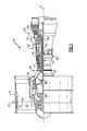
- FIG. 1 schematically illustrates a gas turbine engine 20.
- the gas turbine engine 20 is disclosed herein as a two-spool turbofan that generally incorporates a fan section 22, a compressor section 24, a combustor section 26 and a turbine section 28.
- Alternative engines might include an augmentor section (not shown) among other systems or features.
- the fan section 22 drives air along a bypass flow path B in a bypass duct defined within a nacelle 15, while the compressor section 24 drives air along a core flow path C for compression and communication into the combustor section 26 then expansion through the turbine section 28.
- the exemplary engine 20 generally includes a low speed spool 30 and a high speed spool 32 mounted for rotation about an engine central longitudinal axis A relative to an engine static structure 36 via several bearing systems 38. It should be understood that various bearing systems 38 at various locations may alternatively or additionally be provided, and the location of bearing systems 38 may be varied as appropriate to the application.
- the low speed spool 30 generally includes an inner shaft 40 that interconnects a fan 42, a first (or low) pressure compressor 44 and a first (or low) pressure turbine 46.
- the inner shaft 40 is connected to the fan 42 through a speed change mechanism, which in exemplary gas turbine engine 20 is illustrated as a geared architecture 48 to drive the fan 42 at a lower speed than the low speed spool 30.
- the high speed spool 32 includes an outer shaft 50 that interconnects a second (or high) pressure compressor 52 and a second (or high) pressure turbine 54.
- a combustor 56 is arranged in exemplary gas turbine 20 between the high pressure compressor 52 and the high pressure turbine 54.
- a mid-turbine frame 57 of the engine static structure 36 is arranged generally between the high pressure turbine 54 and the low pressure turbine 46.
- the mid-turbine frame 57 further supports bearing systems 38 in the turbine section 28.
- the inner shaft 40 and the outer shaft 50 are concentric and rotate via bearing systems 38 about the engine central longitudinal axis A which is collinear with their longitudinal axes.
- the core airflow is compressed by the low pressure compressor 44 then the high pressure compressor 52, mixed and burned with fuel in the combustor 56, then expanded over the high pressure turbine 54 and low pressure turbine 46.
- the mid-turbine frame 57 includes airfoils 59 which are in the core airflow path C.
- the turbines 46, 54 rotationally drive the respective low speed spool 30 and high speed spool 32 in response to the expansion.
- gear system 48 may be located aft of combustor section 26 or even aft of turbine section 28, and fan section 22 may be positioned forward or aft of the location of gear system 48.
- the engine 20 in one example is a high-bypass geared aircraft engine.
- the engine 20 bypass ratio is greater than about six (6:1), with an example embodiment being greater than about ten (10:1)
- the geared architecture 48 is an epicyclic gear train, such as a planetary gear system or other gear system, with a gear reduction ratio of greater than about 2.3
- the low pressure turbine 46 has a pressure ratio that is greater than about five (5:1).
- the engine 20 bypass ratio is greater than about ten (10:1)
- the fan diameter is significantly larger than that of the low pressure compressor 44
- the low pressure turbine 46 has a pressure ratio that is greater than about five (5:1).
- Low pressure turbine 46 pressure ratio is pressure measured prior to inlet of low pressure turbine 46 as related to the pressure at the outlet of the low pressure turbine 46 prior to an exhaust nozzle.
- the geared architecture 48 may be an epicycle gear train, such as a planetary gear system or other gear system, with a gear reduction ratio of greater than about 2.3:1. It should be understood, however, that the above parameters are only exemplary of one embodiment of a geared architecture engine and that the present invention is applicable to other gas turbine engines including direct drive turbofans.
- the fan section 22 of the engine 20 is designed for a particular flight condition -- typically cruise at about 0.8 Mach and about 35,000 feet (10, 668 metres).
- the flight condition of 0.8 Mach and 35,000 ft (10,668 metres), with the engine at its best fuel consumption - also known as "bucket cruise Thrust Specific Fuel Consumption ('TSFC')" - is the industry standard parameter of Ibm of fuel being burned divided by lbf of thrust the engine produces at that minimum point.
- "Low fan pressure ratio” is the pressure ratio across the fan blade alone, without a Fan Exit Guide Vane (“FEGV”) system.
- the low fan pressure ratio as disclosed herein according to one non-limiting embodiment is less than about 1.45.
- Low corrected fan tip speed is the actual fan tip speed in ft/sec divided by an industry standard temperature correction of [(Tram °R) / (518.7 °R)] ⁇ 0.5.
- the "Low corrected fan tip speed” as disclosed herein according to one non-limiting embodiment is less than about 1150 ft / second (350.5 m/second).
- the flow correcting vanes span the flow path and have an airfoil shaped profile.
- the airfoil shaped profile is designed to impart desirable flow characteristics on the fluid flowing through the primary flow path.
- the exposure of the vanes to the high temperature fluid flowing through the flow path requires either active or passive cooling in the flow correcting vane in order to extend the lifecycle of the vane.
- the expected lifecycle of the vane is limited by the lifecycle of the least effectively cooled area of the vane.
- the least effectively cooled area of the vane is most frequently the trailing edge, as there is insufficient room in the trailing edge for an internal cooling cavity.
- the damage to this region is limited by using a larger trailing edge radius for the airfoil (i.e. a fatter trailing edge rather than a thin trailing edge). Utilization of this approach comes with an aerodynamic performance penalty which may be offset partially by the cycle benefit of removing trailing edge cooling.
- FIG 2 schematically illustrates a multi-piece flow correcting vane 100 included within a primary flow path 110 of a gas turbine engine 20 (illustrated in Figure 1 ).
- the multi-piece flow correcting vane 100 spans an inner diameter 120 and an outer diameter 130 of the flow path 110 and has an airfoil shaped profile along view line 150.
- the multi-piece flow correcting vane 100 includes a fore portion 102 and a consumable aft portion 104.
- the consumable aft portion 104 is decoupled from the fore portion 102, and has a shorter lifecycle than the fore portion 104.
- a leading edge 106 of the multi-piece flow correcting vane 100 is a foremost edge of the fore component 102, while a trailing edge 108 of the multi-piece flow correcting vane 100 is an aftmost edge of the consumable aft portion 104.
- the fore portion 102 is a cooled component including multiple internal cooling cavities (illustrated in Figures 3 and 4 ). In some examples the fore portion 102 is actively cooled using a known film cooling process. In alternative examples, the fore portion 102 is convectively cooled using only the internal cavities and a cooling fluid.
- the consumable aft portion 104 is a distinct piece from the fore portion 102, and is distanced from the fore portion 102 by a gap 109.
- the consumable aft portion 104 is constructed of a solid material, and is not directly cooled actively.
- the consumable aft portion 104 is constructed of a different material, having different thermal and structural qualities, than the material of the fore portion 102.
- the consumable aft portion 104 is constructed of the same materials and construction as the fore portion 102 but lacks internal cooling cavities.
- the material used to construct at least one of the fore portion 102 and the consumable aft portion 104 include brittle alloys (e.g. a molybdenum alloy), monolithic ceramics, and ceramic matrix composites. Each of these materials is a relatively high temperature material, rendering them suitable for forming an airfoil portion which does not require film cooling.
- the maintenance schedule of the consumable aft portion 104 is scheduled to ensure that both the fore portion 102 and the consumable aft portion are replaced in the same maintenance, with the consumable aft portion 104 having additional scheduled maintenance in between the shared scheduled maintenance.
- the maintenance schedule can incorporate scheduled maintenance and scheduled replacements of the consumable aft portion 104, and is not limited to just repairing or just replacing the components scheduled for maintenance.
- FIG. 3 schematically illustrates a cross section of one example multi-piece flow correcting vane 200 cut along view line 150.
- the multi-piece flow correcting vane 200 includes a cooled fore portion 202 and an uncooled consumable aft portion 204, with a gap 209 disposed between the portions 202, 204.
- the gap 209 is defined along the direction of fluid flow through the flow path in which the multi-piece flow correcting vane 200 is disposed.
- a leading edge 206 of the multi-piece flow correcting vane 200 is at a foremost edge of the fore portion 202, and a trailing edge 208 of the multi-piece flow correcting vane 200 is at an aft most edge of the consumable aft portion 204.
- a pressure surface 260 of the multi-piece flow correcting vane 200 is defined by a first surface 262 of the fore portion and a first surface 264 of the consumable aft portion 202.
- a suction surface 270 of the multi-piece flow correcting vane 200 is defined by a second surface 272 of the fore portion and a second surface 274 of the consumable aft portion 204.
- the illustrated example of Figure 3 passively cools walls 250 by passing a cooling fluid through the cooling cavities 230, 240 of the fore portion 204.
- the magnitude by which the walls 250 are cooled is dependent upon the thickness of the walls 250, with a thicker wall 250 resulting in decreased effective cooling at that wall 250.
- a thickness 220 of the wall 250 at the aftmost edge of the fore portion 202 is similar to the thickness of the remainder of the walls 250.
- the thickness 220 at the aftmost edge would extend the full length of the trailing edge region (corresponding to the consumable aft portion 204). This extensive thickness at the trailing edge results in significantly decreased cooling effectiveness.
- the region of the multi-piece flow correcting vane 200 where the fore portion 202 and the consumable aft portion 204 abut is referred to as a joint region 210.
- the fore edge 212 of the consumable aft portion 204 and the aft edge 214 of the fore portion 202 are rounded in opposite directions with the gap 209 defined between the rounded edges 212, 214.
- the leading edge of the consumable aft portion 204 and the trailing edge of the fore portion 202 can each be one of three general geometries generally square, generally concave, and generally convex. In each of the examples, the gap 209 is maintained between the fore portion 202 and the cons8umable aft portion 204.
- the aft piece could be supported as a cantilever from the outer or inner endwall, simply supported between both, or supported partially or in full by direct attachment to the airfoil itself.
- Figure 4 schematically illustrates a cross section of one example multi-piece flow correcting vane 300 cut along view line 150.
- the multi-piece flow correcting vane 300 includes a cooled fore portion 302 and an uncooled consumable aft portion 304, with a gap 309 disposed between the portions 302, 304.
- the gap 309 is defined along the direction of fluid flow through the flow path in which the multi-piece flow correcting vane 300 is disposed.
- a leading edge 306 of the multi-piece flow correcting vane 300 is at a foremost edge of the fore portion 302, and a trailing edge 308 of the multi-piece flow correcting vane 300 is at an aft most edge of the consumable aft portion 304.
- a pressure surface 360 of the multi-piece flow correcting vane 300 is defined by a first surface 362 of the fore portion and a first surface 364 of the consumable aft portion 302.
- a suction surface 370 of the multi-piece flow correcting vane 300 is defined by a second surface 372 of the fore portion and a second surface 374 of the consumable aft portion 304.
- the walls 350 of the fore portion 302 include multiple film cooling holes 332, 342 providing a fluid outlet to cooling fluid passing through the cooling fluid cavities 330, 340.
- the cooling fluid exits the cooling cavities 330, 340 through the film cooling holes 332, 342 and creates a film cooling layer that actively cools the exterior of the fore portion 302 according to known film cooling techniques.
- a thickness of the wall 350 at the aft most edge of the fore portion 302 is similar to the thickness of the remainder of the walls 350.
- a joint region 310 of the multi-piece flow correcting vane 300 includes a concave surface 312 of the consumable aft portion 304 and a convex surface 314 of the fore portion 302.
- the physical structure of the concave surface 312 and the convex surface 314 are such that the surfaces are complimentary to each other and form a nested arrangement.
- the foremost tips 316 of the consumable aft portion 304 are generally pointed, allowing for a more seamless joint section than a rounded alternative.
- the cooled fore portion 202, 302 can, in alternative examples, be cooled using any other vane/rotor cooling system aside from passive cooling or film cooling.
- the consumable aft portion 204, 304 remains uncooled.
- residual cooling effects may entrain onto the consumable aft portion 204, 304 and provide minimal cooling to the consumable aft portion 204, 304.
- the consumable aft portion 204, 304 is referred to as uncooled, as the residual cooling effect is unintended.
- the consumable aft portion 204, 304 in both examples is a general teardrop shape with a wide end immediately adjacent the fore portion 302.
- the consumable aft portion 304 tapers into a skinny end downstream of the wide end to form the general teardrop shape.
- Alternative profiles including airfoil profiles, rectangular profiles, oval profiles, and the like, can be used for the consumable aft portion 204, 304 in place of the illustrated teardrop profile, depending on the needs of a specific multi-piece flow correcting vane 200, 300.
- Figures 5A and 5B illustrate alternative example joint regions 410, 510.
- the joint region 410 includes a concave surface 414 on the consumable aft portion 404 and a convex surface 414 on the fore portion 402.
- each of the aftmost ends 416 are rounded.
- the specific radius of the rounded edges, and shape of the rounding can be designed by one of skill in the art to achieve specific flow properties at the edges 416.
- Figure 5B illustrates an alternative complimentary surface shape including a post 514 extending from the fore portion 502 into a notch 512 in the consumable aft portion 504.
- the post 514 and notch 512 configuration can provide better alignment between the fore portion and the consumable aft portion 504, and can reduce a cross flow of fluid through the gap 509.
- joint region configurations 210, 310, 410, 510 can be combined in whole or in part to achieve desired flow effects across a multi-piece flow correcting vane.
- the gap 209, 309, 409, 509 can be eliminated entirely by installing the consumable aft portion 204, 304, 404, 504 such that the consumable aft portion 204, 304, 404, 504 abuts the fore portion 202, 302, 402, 502.
- multi-piece airfoil component can be applied to a rotating blade disposed within a flow path, or a partial vane disposed within a flow path with minimal structural modifications.
- the modified examples achieve all the benefits described above, and fall within the instant disclosure.
Landscapes
- Engineering & Computer Science (AREA)
- Mechanical Engineering (AREA)
- General Engineering & Computer Science (AREA)
- Physics & Mathematics (AREA)
- Geometry (AREA)
- Chemical & Material Sciences (AREA)
- Combustion & Propulsion (AREA)
- Fluid Mechanics (AREA)
- Architecture (AREA)
- Turbine Rotor Nozzle Sealing (AREA)
Abstract
Description
- The present disclosure relates generally to airfoils for gas powered turbines, and more specifically to a multi-piece airfoil.
- Gas powered turbines, such as those utilized an a gas turbine engine for an aircraft, include a compressor that draws in and compresses air, a combustor where the compressed air is mixed with a fuel and ignited, and a turbine where the resultant combustion gases are expanded. As the resultant combustion gasses expand across the turbine, the turbine is driven to rotate. The turbine is, in turn, connected to the compressor via a shaft, and drives the compressor to rotate.
- Each of the compressor, combustor and turbine are interconnected via a core flow path that passes through the gas powered turbine. In order to ensure that gas flowing through the flow path has desirable flow characteristics, multiple flow correcting vanes, or other airfoil shaped turbine components, are included within the flow path. During operation of the gas powered turbine, the gases flowing through the core flow path can heat the flow correcting vane, requiring the turbine airfoil to be cooled.
- In one exemplary embodiment a gas turbine engine includes a compressor, a combustor fluidly connected to the compressor via a flow path, and a turbine fluidly connected to the combustor via the flow path. At least one multi-piece structure is disposed within the flow path such that the multi-piece structure at least partially radially spans the flow path. The at least one multi-piece structure includes a fore portion defining a leading edge, a consumable aft portion defining a trailing edge, a pressure surface at least partially defined by a first surface of the fore portion and a first surface of the consumable aft portion, and a suction surface at least partially defined by a second surface of the fore portion and a second surface of the consumable aft portion.
- Another exemplary embodiment of the above described gas turbine engine includes an axial gap defined between the fore portion and the consumable aft portion.
- In another exemplary embodiment of any of the above described gas turbine engines, the fore portion has at least one internal cooling cavity.
- In another exemplary embodiment of any of the above described gas turbine engines, the consumable aft portion is a solid component.
- In another exemplary embodiment of any of the above described gas turbine engines, the fore portion has a first replacement frequency, the consumable aft portion has a second replacement frequency, and the second replacement frequency is more frequent than the first replacement frequency.
- In another exemplary embodiment of any of the above described gas turbine engines, a foremost surface of the aft consumable portion and an aftmost surface of the fore portion are complimentary surfaces.
- In another exemplary embodiment of any of the above described gas turbine engines, the aftmost surface of the fore portion includes a protrusion, wherein the foremost surface of the consumable aft portion includes a notch, and wherein the protrusion is received in the notch.
- In another exemplary embodiment of any of the above described gas turbine engines, the foremost edge of the aft consumable portion defines a concave surface, and wherein the aftmost edge of the fore portion defines a convex surface.
- In another exemplary embodiment of any of the above described gas turbine engines, the foremost edge of the aft consumable portion and the aftmost edge of the fore portion are one of generally square, generally concave, and generally convex.
- In another exemplary embodiment of any of the above described gas turbine engines, at least one of the fore portion and the consumable aft portion is constructed of a material selected from brittle alloys, monolithic ceramics, and ceramic matrix composites.
- In another exemplary embodiment of any of the above described gas turbine engines, the consumable aft portion has a teardrop shaped profile.
- In another exemplary embodiment of any of the above described gas turbine engines, the at least one multi-piece structure is a multi-piece flow correcting vane, and wherein the at least one multi-piece structure has an airfoil profile.
- An exemplary method for maintaining a multi-piece flow correcting vane, includes performing maintenance on a consumable aft portion of a multi-piece flow correcting vane according to a first maintenance schedule, and performing maintenance on a fore portion of the multi-piece flow correcting vane according to a second maintenance schedule. The first maintenance schedule is more frequent than the second maintenance schedule.
- In a further example of the above exemplary method, performing maintenance on a consumable aft portion of a multi-piece flow correcting vane comprises removing the consumable aft portion from the multi-piece flow correcting vane and at least one of repairing and replacing the consumable aft portion.
- In one exemplary embodiment a gas turbine engine includes a compressor, a combustor fluidly connected to the compressor via a flow path; a turbine fluidly connected to the combustor via the flow path, and at least one multi-piece structure disposed within the flow path such that the multi-piece structure at least partially radially spans the flow path. The at least one multi-piece structure includes a fore portion defining a leading edge, a consumable aft portion defining a trailing edge, and an axial gap defined between the fore portion and the consumable aft portion.
- In another exemplary example of the above described gas turbine engine, the at least one multi-piece structure is a multi-piece flow correcting vane having a pressure surface defined by a first surface of the fore portion and a first surface of the consumable aft portion and a suction surface defined by a second surface of the fore portion and a second surface of the consumable aft portion, and wherein the at least one multi-piece flow correcting vane completely radially spans the flow path.
- In another exemplary embodiment of any of the above described gas turbine engines, the fore portion has a first maintenance frequency, the consumable aft portion has a second maintenance frequency, and the second maintenance frequency is more frequent than the first maintenance frequency.
- In another exemplary embodiment of any of the above described gas turbine engines, a foremost surface of the aft consumable portion and an aftmost surface of the fore portion are complimentary surfaces.
- In another exemplary embodiment of any of the above described gas turbine engines, the aftmost surface of the fore portion includes a protrusion, wherein the foremost surface of the consumable aft portion includes a notch, and wherein the protrusion is received in the notch.
- In another exemplary embodiment of any of the above described gas turbine engines, the consumable aft portion has a teardrop shaped profile.
- These and other features of the present invention can be best understood from the following specification and drawings, the following of which is a brief description.
-
-
Figure 1 schematically illustrates an example gas turbine engine. -
Figure 2 schematically illustrates a side view of a multi-piece flow correcting vane for a gas turbine engine. -
Figure 3 schematically illustrates a cross sectional view of one example multi-piece flow correcting vane cut alongview line 150. -
Figure 4 schematically illustrates a cross sectional view of an alternate multi-piece flow correcting vane cut alongview line 150. -
Figure 5A schematically illustrates a first example joint between a consumable aft portion and a fore portion of a multi-piece flow correcting vane. -
Figure 5B schematically illustrates a second example joint between a consumable aft portion and a fore portion of a multi-piece flow correcting vane. -
Figure 1 schematically illustrates agas turbine engine 20. Thegas turbine engine 20 is disclosed herein as a two-spool turbofan that generally incorporates afan section 22, acompressor section 24, acombustor section 26 and aturbine section 28. Alternative engines might include an augmentor section (not shown) among other systems or features. Thefan section 22 drives air along a bypass flow path B in a bypass duct defined within anacelle 15, while thecompressor section 24 drives air along a core flow path C for compression and communication into thecombustor section 26 then expansion through theturbine section 28. Although depicted as a two-spool turbofan gas turbine engine in the disclosed non-limiting embodiment, it should be understood that the concepts described herein are not limited to use with two-spool turbofans as the teachings may be applied to other types of turbine engines including three-spool architectures. - The
exemplary engine 20 generally includes alow speed spool 30 and ahigh speed spool 32 mounted for rotation about an engine central longitudinal axis A relative to an enginestatic structure 36 viaseveral bearing systems 38. It should be understood thatvarious bearing systems 38 at various locations may alternatively or additionally be provided, and the location ofbearing systems 38 may be varied as appropriate to the application. - The
low speed spool 30 generally includes aninner shaft 40 that interconnects afan 42, a first (or low)pressure compressor 44 and a first (or low)pressure turbine 46. Theinner shaft 40 is connected to thefan 42 through a speed change mechanism, which in exemplarygas turbine engine 20 is illustrated as a gearedarchitecture 48 to drive thefan 42 at a lower speed than thelow speed spool 30. Thehigh speed spool 32 includes anouter shaft 50 that interconnects a second (or high)pressure compressor 52 and a second (or high)pressure turbine 54. Acombustor 56 is arranged inexemplary gas turbine 20 between thehigh pressure compressor 52 and thehigh pressure turbine 54. Amid-turbine frame 57 of the enginestatic structure 36 is arranged generally between thehigh pressure turbine 54 and thelow pressure turbine 46. Themid-turbine frame 57 further supports bearingsystems 38 in theturbine section 28. Theinner shaft 40 and theouter shaft 50 are concentric and rotate viabearing systems 38 about the engine central longitudinal axis A which is collinear with their longitudinal axes. - The core airflow is compressed by the
low pressure compressor 44 then thehigh pressure compressor 52, mixed and burned with fuel in thecombustor 56, then expanded over thehigh pressure turbine 54 andlow pressure turbine 46. Themid-turbine frame 57 includesairfoils 59 which are in the core airflow path C. Theturbines low speed spool 30 andhigh speed spool 32 in response to the expansion. It will be appreciated that each of the positions of thefan section 22,compressor section 24,combustor section 26,turbine section 28, and fandrive gear system 48 may be varied. For example,gear system 48 may be located aft ofcombustor section 26 or even aft ofturbine section 28, andfan section 22 may be positioned forward or aft of the location ofgear system 48. - The
engine 20 in one example is a high-bypass geared aircraft engine. In a further example, theengine 20 bypass ratio is greater than about six (6:1), with an example embodiment being greater than about ten (10:1), the gearedarchitecture 48 is an epicyclic gear train, such as a planetary gear system or other gear system, with a gear reduction ratio of greater than about 2.3 and thelow pressure turbine 46 has a pressure ratio that is greater than about five (5:1). In one disclosed embodiment, theengine 20 bypass ratio is greater than about ten (10:1), the fan diameter is significantly larger than that of thelow pressure compressor 44, and thelow pressure turbine 46 has a pressure ratio that is greater than about five (5:1).Low pressure turbine 46 pressure ratio is pressure measured prior to inlet oflow pressure turbine 46 as related to the pressure at the outlet of thelow pressure turbine 46 prior to an exhaust nozzle. The gearedarchitecture 48 may be an epicycle gear train, such as a planetary gear system or other gear system, with a gear reduction ratio of greater than about 2.3:1. It should be understood, however, that the above parameters are only exemplary of one embodiment of a geared architecture engine and that the present invention is applicable to other gas turbine engines including direct drive turbofans. - A significant amount of thrust is provided by the bypass flow B due to the high bypass ratio. The
fan section 22 of theengine 20 is designed for a particular flight condition -- typically cruise at about 0.8 Mach and about 35,000 feet (10, 668 metres). The flight condition of 0.8 Mach and 35,000 ft (10,668 metres), with the engine at its best fuel consumption - also known as "bucket cruise Thrust Specific Fuel Consumption ('TSFC')" - is the industry standard parameter of Ibm of fuel being burned divided by lbf of thrust the engine produces at that minimum point. "Low fan pressure ratio" is the pressure ratio across the fan blade alone, without a Fan Exit Guide Vane ("FEGV") system. The low fan pressure ratio as disclosed herein according to one non-limiting embodiment is less than about 1.45. "Low corrected fan tip speed" is the actual fan tip speed in ft/sec divided by an industry standard temperature correction of [(Tram °R) / (518.7 °R)]^0.5. The "Low corrected fan tip speed" as disclosed herein according to one non-limiting embodiment is less than about 1150 ft / second (350.5 m/second). - In order to ensure proper fluid flow through the primary flow path, multiple flow correcting vanes are utilized in the flow path. The flow correcting vanes span the flow path and have an airfoil shaped profile. The airfoil shaped profile is designed to impart desirable flow characteristics on the fluid flowing through the primary flow path. In practice, the exposure of the vanes to the high temperature fluid flowing through the flow path requires either active or passive cooling in the flow correcting vane in order to extend the lifecycle of the vane. As a typical vane is a single monolithic component, the expected lifecycle of the vane is limited by the lifecycle of the least effectively cooled area of the vane. The least effectively cooled area of the vane is most frequently the trailing edge, as there is insufficient room in the trailing edge for an internal cooling cavity. This lack of internal cavity space for convective cooling motivates the use of film cooling at the trailing edge in existing systems. Film cooling, in turn, comes with a performance penalty and which may be structurally intolerable for brittle materials. As a result of the insufficient cooling, oxidation, corrosion, and fatigue damage can occur within the trailing edge, thereby reducing the lifespan of the flow correcting vane.
- In some previous examples, the damage to this region is limited by using a larger trailing edge radius for the airfoil (i.e. a fatter trailing edge rather than a thin trailing edge). Utilization of this approach comes with an aerodynamic performance penalty which may be offset partially by the cycle benefit of removing trailing edge cooling.
-
Figure 2 schematically illustrates a multi-pieceflow correcting vane 100 included within a primary flow path 110 of a gas turbine engine 20 (illustrated inFigure 1 ). The multi-pieceflow correcting vane 100 spans aninner diameter 120 and an outer diameter 130 of the flow path 110 and has an airfoil shaped profile alongview line 150. The multi-pieceflow correcting vane 100 includes afore portion 102 and a consumableaft portion 104. The consumableaft portion 104 is decoupled from thefore portion 102, and has a shorter lifecycle than thefore portion 104. - A
leading edge 106 of the multi-pieceflow correcting vane 100 is a foremost edge of thefore component 102, while a trailingedge 108 of the multi-pieceflow correcting vane 100 is an aftmost edge of the consumableaft portion 104. Thefore portion 102 is a cooled component including multiple internal cooling cavities (illustrated inFigures 3 and4 ). In some examples thefore portion 102 is actively cooled using a known film cooling process. In alternative examples, thefore portion 102 is convectively cooled using only the internal cavities and a cooling fluid. - The consumable
aft portion 104 is a distinct piece from thefore portion 102, and is distanced from thefore portion 102 by agap 109. The consumableaft portion 104 is constructed of a solid material, and is not directly cooled actively. In some examples, the consumableaft portion 104 is constructed of a different material, having different thermal and structural qualities, than the material of thefore portion 102. In alternative examples, the consumableaft portion 104 is constructed of the same materials and construction as thefore portion 102 but lacks internal cooling cavities. - In some examples, the material used to construct at least one of the
fore portion 102 and the consumableaft portion 104 include brittle alloys (e.g. a molybdenum alloy), monolithic ceramics, and ceramic matrix composites. Each of these materials is a relatively high temperature material, rendering them suitable for forming an airfoil portion which does not require film cooling. - During practical operation of the
turbine engine 20, heat from a fluid 140 flowing through the flow path 110 heats up the multi-pieceflow correcting vane 100. The active or passive cooling within thefore portion 102 of themulti-piece vane 100 extends the lifecycle of thefore portion 102. The consumableaft portion 104, however is not cooled and is "consumed" (deteriorates at a faster rate than thefore portion 102.) In order to compensate for this, the consumableaft portion 104 has a more frequent maintenance schedule. In some examples, the maintenance schedule of the consumableaft portion 104 is scheduled to ensure that both thefore portion 102 and the consumable aft portion are replaced in the same maintenance, with the consumableaft portion 104 having additional scheduled maintenance in between the shared scheduled maintenance. By ensuring that the maintenance scheduling of thefore portion 104 coincides with a maintenance scheduling of the consumableaft portion 104, the number of maintenances is minimized. Further, the maintenance schedule can incorporate scheduled maintenance and scheduled replacements of the consumableaft portion 104, and is not limited to just repairing or just replacing the components scheduled for maintenance. - With continued reference to
Figure 2, Figure 3 schematically illustrates a cross section of one example multi-pieceflow correcting vane 200 cut alongview line 150. The multi-pieceflow correcting vane 200 includes a cooledfore portion 202 and an uncooled consumableaft portion 204, with agap 209 disposed between theportions gap 209 is defined along the direction of fluid flow through the flow path in which the multi-pieceflow correcting vane 200 is disposed. Aleading edge 206 of the multi-pieceflow correcting vane 200 is at a foremost edge of thefore portion 202, and a trailingedge 208 of the multi-pieceflow correcting vane 200 is at an aft most edge of the consumableaft portion 204. Apressure surface 260 of the multi-pieceflow correcting vane 200 is defined by afirst surface 262 of the fore portion and afirst surface 264 of the consumableaft portion 202. Similarly, asuction surface 270 of the multi-pieceflow correcting vane 200 is defined by asecond surface 272 of the fore portion and asecond surface 274 of the consumableaft portion 204. - Contained within the
fore portion 202 are multiple coolingcavities Figure 3 passively coolswalls 250 by passing a cooling fluid through the coolingcavities fore portion 204. The magnitude by which thewalls 250 are cooled is dependent upon the thickness of thewalls 250, with athicker wall 250 resulting in decreased effective cooling at thatwall 250. In the illustrated example ofFigure 3 , athickness 220 of thewall 250 at the aftmost edge of thefore portion 202 is similar to the thickness of the remainder of thewalls 250. In contrast, in a single piece flow correcting vane, thethickness 220 at the aftmost edge would extend the full length of the trailing edge region (corresponding to the consumable aft portion 204). This extensive thickness at the trailing edge results in significantly decreased cooling effectiveness. - The region of the multi-piece
flow correcting vane 200 where thefore portion 202 and the consumableaft portion 204 abut is referred to as ajoint region 210. In the illustrated example, thefore edge 212 of the consumableaft portion 204 and theaft edge 214 of thefore portion 202 are rounded in opposite directions with thegap 209 defined between therounded edges - In some examples, the leading edge of the consumable
aft portion 204 and the trailing edge of thefore portion 202 can each be one of three general geometries generally square, generally concave, and generally convex. In each of the examples, thegap 209 is maintained between thefore portion 202 and the cons8umable aftportion 204. - With regard to attachment, we can mention that the aft piece could be supported as a cantilever from the outer or inner endwall, simply supported between both, or supported partially or in full by direct attachment to the airfoil itself.
- Alternative example
joint regions 210 are illustrated inFigures 4, 5A and 5B . One of skill in the art, having the benefit of this disclosure, will understand that the features of the alternative joint regions can be applied in place of, or in combination with, the features of the illustratedjoint region 210. - With continued reference to
Figures 2 and 3 ,Figure 4 schematically illustrates a cross section of one example multi-pieceflow correcting vane 300 cut alongview line 150. As with the example ofFigure 3 , the multi-pieceflow correcting vane 300 includes a cooledfore portion 302 and an uncooled consumableaft portion 304, with agap 309 disposed between theportions gap 309 is defined along the direction of fluid flow through the flow path in which the multi-pieceflow correcting vane 300 is disposed. A leading edge 306 of the multi-pieceflow correcting vane 300 is at a foremost edge of thefore portion 302, and a trailing edge 308 of the multi-pieceflow correcting vane 300 is at an aft most edge of the consumableaft portion 304. Apressure surface 360 of the multi-pieceflow correcting vane 300 is defined by afirst surface 362 of the fore portion and afirst surface 364 of the consumableaft portion 302. Similarly, asuction surface 370 of the multi-pieceflow correcting vane 300 is defined by asecond surface 372 of the fore portion and asecond surface 374 of the consumableaft portion 304. - Contained within the
fore portion 302 are multiple coolingcavities walls 350 of thefore portion 302 include multiple film cooling holes 332, 342 providing a fluid outlet to cooling fluid passing through the coolingfluid cavities cavities fore portion 302 according to known film cooling techniques. - As with the passive cooling of
Figure 3 , the magnitude by which thewalls 350 are cooled is dependent upon the thickness of thewalls 350, with athicker wall 350 resulting in decreased effective cooling at thatwall 350. Further, in the illustrated example ofFigure 4 , a thickness of thewall 350 at the aft most edge of thefore portion 302 is similar to the thickness of the remainder of thewalls 350. - A
joint region 310 of the multi-pieceflow correcting vane 300 includes aconcave surface 312 of the consumableaft portion 304 and aconvex surface 314 of thefore portion 302. The physical structure of theconcave surface 312 and theconvex surface 314 are such that the surfaces are complimentary to each other and form a nested arrangement. Theforemost tips 316 of the consumableaft portion 304 are generally pointed, allowing for a more seamless joint section than a rounded alternative. - With collective reference to the examples of
Figures 3 and4 , the cooledfore portion aft portion aft portion aft portion aft portion - With further collective reference to
Figures 3 and4 , the consumableaft portion fore portion 302. The consumableaft portion 304 tapers into a skinny end downstream of the wide end to form the general teardrop shape. Alternative profiles, including airfoil profiles, rectangular profiles, oval profiles, and the like, can be used for the consumableaft portion flow correcting vane - With continued reference to
Figures 2-4 ,Figures 5A and 5B illustrate alternative examplejoint regions Figure 5A , thejoint region 410 includes aconcave surface 414 on the consumableaft portion 404 and aconvex surface 414 on thefore portion 402. Unlike thejoint region 310 illustrated inFigure 4 , each of the aftmost ends 416 are rounded. The specific radius of the rounded edges, and shape of the rounding can be designed by one of skill in the art to achieve specific flow properties at theedges 416. -
Figure 5B illustrates an alternative complimentary surface shape including apost 514 extending from thefore portion 502 into anotch 512 in the consumableaft portion 504. Thepost 514 and notch 512 configuration can provide better alignment between the fore portion and the consumableaft portion 504, and can reduce a cross flow of fluid through thegap 509. - One of skill in the art, having the benefit of this disclosure, will further understand that the illustrated
joint region configurations - In yet a further example, the
gap aft portion aft portion fore portion - While illustrated and described above with regards to a gas powered turbine, such as a geared turbofan engine, one of skill in the art having the benefit of this disclosure will understand that the illustrated and described concepts can be applied to alternative turbine designs including, but not limited to, land based turbines, marine based turbines, and direct drive turbofan engines.
- Furthermore, while illustrated and described above as a flow correcting vane fully spanning a fluid flow path, ne of skill in the art, having the benefit of this disclosure will understand that multi-piece airfoil component can be applied to a rotating blade disposed within a flow path, or a partial vane disposed within a flow path with minimal structural modifications. The modified examples achieve all the benefits described above, and fall within the instant disclosure.
- It is further understood that any of the above described concepts can be used alone or in combination with any or all of the other above described concepts. Although an embodiment of this invention has been disclosed, a worker of ordinary skill in this art would recognize that certain modifications would come within the scope of this invention. For that reason, the following claims should be studied to determine the true scope and content of this invention.
Claims (15)
- A gas turbine engine (20) comprising:a compressor (52);a combustor (56) fluidly connected to the compressor (52) via a flow path;a turbine (54) fluidly connected to the combustor (56) via the flow path;at least one multi-piece structure (100; 200; 300) disposed within said flow path such that the multi-piece structure (100; 200; 300) at least partially radially spans the flow path, and wherein the at least one multi-piece structure (100; 200; 300) includes:a fore portion (102; 202; 302; 402; 502) defining a leading edge (106; 208);a consumable aft portion (104; 204; 304; 404; 504) defining a trailing edge (108; 208);a pressure surface (260; 360) at least partially defined by a first surface of said fore portion (102... 502) and a first surface of said consumable aft portion (104...504);a suction surface (270; 370) at least partially defined by a second surface of said fore portion (102... 502) and a second surface of said consumable aft portion (104... 504).
- The gas turbine engine (20) of claim 1, further comprising an axial gap (109; 209; 309; 409; 509) defined between said fore portion (102...502) and said consumable aft portion (104... 504).
- The gas turbine engine (20) of claim 1 or 2, wherein the fore portion (102...502) has at least one internal cooling cavity.
- The gas turbine engine (20) of claim 1, 2 or 3 wherein the consumable aft portion (104...504) is a solid component.
- The gas turbine engine (20) of any preceding claim, wherein the fore portion (102...502) has a first replacement frequency, the consumable aft portion (104...504) has a second replacement frequency, and the second replacement frequency is more frequent than the first replacement frequency.
- The gas turbine engine (20) of any preceding claim, wherein a foremost surface of the aft consumable portion (304...504) and an aftmost surface of the fore portion (302...502) are complementary surfaces, and optionally the aftmost surface of the fore portion (502) includes a protrusion (514), the foremost surface of the consumable aft portion (504) includes a notch (512), and the protrusion (514) is received in the notch (512).
- The gas turbine engine (20) of any preceding claim, wherein:the foremost edge of the aft consumable portion (304; 404) defines a concave surface (312; 412), and the aftmost edge of the fore portion (302; 402) defines a convex surface (314; 414); orthe foremost edge of the aft consumable portion (104...504) and the aftmost edge of the fore portion (102...502) are one of generally square, generally concave, and generally convex.
- The gas turbine engine (20) of any preceding claim, wherein the fore portion (102...502) and/or the consumable aft portion (104...504) is constructed of a material selected from brittle alloys, monolithic ceramics, and ceramic matrix composites.
- The gas turbine engine (20) of any preceding claim, wherein the at least one multi-piece structure (100...300) is a multi-piece flow correcting vane, and the at least one multi-piece structure (100...300) has an airfoil profile.
- A gas turbine engine (20) comprising:a compressor (52);a combustor (56) fluidly connected to the compressor (52) via a flow path;a turbine (54) fluidly connected to the combustor (56) via the flow path;at least one multi-piece structure (100...300) disposed within said flow path such that the multi-piece structure (100...300) at least partially radially spans the flow path, and wherein the at least one multi-piece structure (100...300) includes:a fore portion (102...502) defining a leading edge (106; 206);a consumable aft portion (104...504) defining a trailing edge (108; 208); andan axial gap (109... 509) defined between said fore portion (102...502) and said consumable aft portion (104...504).
- The gas turbine engine (20) of claim 10, wherein said at least one multi-piece structure is a multi-piece flow correcting vane (100...300) having a pressure surface (260;360) defined by a first surface of said fore portion (102...302) and a first surface of said consumable aft portion (104...304) and a suction surface (270; 370) defined by a second surface of said fore portion (102...302) and a second surface of said consumable aft portion (104...304), and said at least one multi-piece flow correcting vane (100...300) completely radially spans the flow path.
- The gas turbine engine (20) of claim 10 or 11, wherein the fore portion (102...502) has a first maintenance frequency, the consumable aft portion (104...504) has a second maintenance frequency, and the second maintenance frequency is more frequent than the first maintenance frequency.
- The gas turbine engine (20) of claim 10, 11 or 12, wherein a foremost surface of the aft consumable portion (304...504) and an aftmost surface of the fore portion (302...502) are complementary surfaces, and optionally wherein the aftmost surface of the fore portion (502) includes a protrusion (514), wherein the foremost surface of the consumable aft portion (504) includes a notch (512), and wherein the protrusion (514) is received in the notch (512).
- The gas turbine engine (20) of any preceding claim, wherein the consumable aft portion (304) has a teardrop shaped profile.
- A method for maintaining a multi-piece flow correcting vane (100...300), comprising:performing maintenance on a consumable aft portion (104...504) of a multi-piece flow correcting vane (100...300) according to a first maintenance schedule; andperforming maintenance on a fore portion (102...502) of the multi-piece flow correcting vane (100...300) according to a second maintenance schedule, wherein the first maintenance schedule is more frequent than the second maintenance schedule, and optionally wherein performing maintenance on a consumable aft portion (104...504) of a multi-piece flow correcting vane (100...300) comprises removing the consumable aft portion (104...504) from the multi-piece flow correcting vane (100...300) and repairing and/or replacing the consumable aft portion (104...504).
Applications Claiming Priority (1)
| Application Number | Priority Date | Filing Date | Title |
|---|---|---|---|
| US201462068097P | 2014-10-24 | 2014-10-24 |
Publications (2)
| Publication Number | Publication Date |
|---|---|
| EP3012412A1 true EP3012412A1 (en) | 2016-04-27 |
| EP3012412B1 EP3012412B1 (en) | 2022-03-09 |
Family
ID=54360138
Family Applications (1)
| Application Number | Title | Priority Date | Filing Date |
|---|---|---|---|
| EP15191214.4A Active EP3012412B1 (en) | 2014-10-24 | 2015-10-23 | Gas turbine engine and corresponding method for maintaining a multi-piece flow correcting vane. |
Country Status (2)
| Country | Link |
|---|---|
| US (1) | US10801340B2 (en) |
| EP (1) | EP3012412B1 (en) |
Families Citing this family (1)
| Publication number | Priority date | Publication date | Assignee | Title |
|---|---|---|---|---|
| FR3155026A1 (en) * | 2023-11-03 | 2025-05-09 | Safran Aircraft Engines | Stator blade with a slot |
Citations (12)
| Publication number | Priority date | Publication date | Assignee | Title |
|---|---|---|---|---|
| JPS6189903A (en) * | 1984-10-11 | 1986-05-08 | Central Res Inst Of Electric Power Ind | Ceramic stator blade thermal shock resistant structure |
| US5785498A (en) * | 1994-09-30 | 1998-07-28 | General Electric Company | Composite fan blade trailing edge reinforcement |
| EP1489264A1 (en) * | 2003-06-18 | 2004-12-22 | Siemens Aktiengesellschaft | Blade consisting of moduls |
| US20060226290A1 (en) * | 2005-04-07 | 2006-10-12 | Siemens Westinghouse Power Corporation | Vane assembly with metal trailing edge segment |
| US20060285973A1 (en) * | 2005-06-17 | 2006-12-21 | Siemens Westinghouse Power Corporation | Trailing edge attachment for composite airfoil |
| US20080203236A1 (en) * | 2007-02-27 | 2008-08-28 | Siemens Power Generation, Inc. | CMC airfoil with thin trailing edge |
| US20100080687A1 (en) * | 2008-09-26 | 2010-04-01 | Siemens Power Generation, Inc. | Multiple Piece Turbine Engine Airfoil with a Structural Spar |
| EP2213839A2 (en) * | 2009-01-28 | 2010-08-04 | United Technologies Corporation | Segmented ceramic component for a gas turbine engine |
| FR2988786A1 (en) * | 2012-03-28 | 2013-10-04 | Snecma | AUB ON BOARD (S) REINFORCED (S) FOR A TURBOMACHINE |
| US20140227100A1 (en) * | 2011-09-23 | 2014-08-14 | Howden Solyvent-Ventect | Rotating Machine Blade with Reinforced Modular Structure |
| WO2015091289A2 (en) * | 2013-12-20 | 2015-06-25 | Alstom Technology Ltd | Rotor blade or guide vane assembly |
| WO2015191041A1 (en) * | 2014-06-10 | 2015-12-17 | Siemens Energy, Inc. | Trailing edge insert for an airfoil within a gas turbine engine |
Family Cites Families (8)
| Publication number | Priority date | Publication date | Assignee | Title |
|---|---|---|---|---|
| US6045325A (en) * | 1997-12-18 | 2000-04-04 | United Technologies Corporation | Apparatus for minimizing inlet airflow turbulence in a gas turbine engine |
| US6206638B1 (en) | 1999-02-12 | 2001-03-27 | General Electric Company | Low cost airfoil cooling circuit with sidewall impingement cooling chambers |
| KR100690674B1 (en) | 2005-04-06 | 2007-03-09 | 엘지전자 주식회사 | Operation control device of refrigerator with two reciprocating compressors |
| US7452182B2 (en) * | 2005-04-07 | 2008-11-18 | Siemens Energy, Inc. | Multi-piece turbine vane assembly |
| JP5809242B2 (en) | 2010-04-21 | 2015-11-10 | アッヴィ バイオテクノロジー リミテッド | Wearable automatic infusion device for controlled delivery of therapeutic agents |
| US9011085B2 (en) | 2011-05-26 | 2015-04-21 | United Technologies Corporation | Ceramic matrix composite continuous “I”-shaped fiber geometry airfoil for a gas turbine engine |
| EP2685047A1 (en) | 2012-07-13 | 2014-01-15 | Alstom Technology Ltd | Modular vane/blade for a gas turbine and gas turbine with such a vane/blade |
| US20140161616A1 (en) | 2012-12-12 | 2014-06-12 | United Technologies Corporation | Multi-piece blade for gas turbine engine |
-
2015
- 2015-10-20 US US14/887,847 patent/US10801340B2/en not_active Expired - Fee Related
- 2015-10-23 EP EP15191214.4A patent/EP3012412B1/en active Active
Patent Citations (13)
| Publication number | Priority date | Publication date | Assignee | Title |
|---|---|---|---|---|
| JPS6189903A (en) * | 1984-10-11 | 1986-05-08 | Central Res Inst Of Electric Power Ind | Ceramic stator blade thermal shock resistant structure |
| US5785498A (en) * | 1994-09-30 | 1998-07-28 | General Electric Company | Composite fan blade trailing edge reinforcement |
| EP1489264A1 (en) * | 2003-06-18 | 2004-12-22 | Siemens Aktiengesellschaft | Blade consisting of moduls |
| US20060226290A1 (en) * | 2005-04-07 | 2006-10-12 | Siemens Westinghouse Power Corporation | Vane assembly with metal trailing edge segment |
| US20060285973A1 (en) * | 2005-06-17 | 2006-12-21 | Siemens Westinghouse Power Corporation | Trailing edge attachment for composite airfoil |
| US20080203236A1 (en) * | 2007-02-27 | 2008-08-28 | Siemens Power Generation, Inc. | CMC airfoil with thin trailing edge |
| US20100080687A1 (en) * | 2008-09-26 | 2010-04-01 | Siemens Power Generation, Inc. | Multiple Piece Turbine Engine Airfoil with a Structural Spar |
| EP2213839A2 (en) * | 2009-01-28 | 2010-08-04 | United Technologies Corporation | Segmented ceramic component for a gas turbine engine |
| US20140227100A1 (en) * | 2011-09-23 | 2014-08-14 | Howden Solyvent-Ventect | Rotating Machine Blade with Reinforced Modular Structure |
| FR2988786A1 (en) * | 2012-03-28 | 2013-10-04 | Snecma | AUB ON BOARD (S) REINFORCED (S) FOR A TURBOMACHINE |
| US20150026980A1 (en) * | 2012-03-28 | 2015-01-29 | Snecma | Method for disassembling a reinforcement from a part |
| WO2015091289A2 (en) * | 2013-12-20 | 2015-06-25 | Alstom Technology Ltd | Rotor blade or guide vane assembly |
| WO2015191041A1 (en) * | 2014-06-10 | 2015-12-17 | Siemens Energy, Inc. | Trailing edge insert for an airfoil within a gas turbine engine |
Also Published As
| Publication number | Publication date |
|---|---|
| US20160115801A1 (en) | 2016-04-28 |
| US10801340B2 (en) | 2020-10-13 |
| EP3012412B1 (en) | 2022-03-09 |
Similar Documents
| Publication | Publication Date | Title |
|---|---|---|
| US11143039B2 (en) | Turbine engine component including an axially aligned skin core passage interrupted by a pedestal | |
| US10323524B2 (en) | Axial skin core cooling passage for a turbine engine component | |
| US10794206B2 (en) | CMC BOAS intersegment seal | |
| US20160326898A1 (en) | Seal arrangement for turbine engine component | |
| US20190345833A1 (en) | Vane including internal radiant heat shield | |
| US20190368359A1 (en) | Squealer shelf airfoil tip | |
| EP3255249A1 (en) | Gas turbine engine blade including squealer tip pocket | |
| EP3812551B1 (en) | Vane with l-shaped seal | |
| US10443421B2 (en) | Turbomachine blade assemblies | |
| EP2971548B1 (en) | Knife edge seal for a gas turbine engine, gas turbine engine and method of sealing a high pressure area from a low pressure area in a gas turbine engine | |
| EP3461993B1 (en) | Gas turbine engine blade | |
| US10794194B2 (en) | Staggered core printout | |
| EP3112596A1 (en) | Gas turbine engine airfoil with bi-axial skin cooling passage and corresponding gas turbine engine | |
| US10641098B2 (en) | Gas turbine engine hollow fan blade rib orientation | |
| EP3176376B1 (en) | Cooling passages for a gas path component of a gas turbine engine | |
| US10196915B2 (en) | Trailing edge platform seals | |
| US10801340B2 (en) | Multi-piece turbine airfoil | |
| EP4253726B1 (en) | Cmc vane mate face flanges with through-ply seal slots | |
| US20160194969A1 (en) | Turbine Vane With Platform Rib | |
| US20250067189A1 (en) | Cmc vane arc segments with friction damper |
Legal Events
| Date | Code | Title | Description |
|---|---|---|---|
| PUAI | Public reference made under article 153(3) epc to a published international application that has entered the european phase |
Free format text: ORIGINAL CODE: 0009012 |
|
| AK | Designated contracting states |
Kind code of ref document: A1 Designated state(s): AL AT BE BG CH CY CZ DE DK EE ES FI FR GB GR HR HU IE IS IT LI LT LU LV MC MK MT NL NO PL PT RO RS SE SI SK SM TR |
|
| AX | Request for extension of the european patent |
Extension state: BA ME |
|
| RAP1 | Party data changed (applicant data changed or rights of an application transferred) |
Owner name: UNITED TECHNOLOGIES CORPORATION |
|
| STAA | Information on the status of an ep patent application or granted ep patent |
Free format text: STATUS: REQUEST FOR EXAMINATION WAS MADE |
|
| 17P | Request for examination filed |
Effective date: 20161027 |
|
| RBV | Designated contracting states (corrected) |
Designated state(s): AL AT BE BG CH CY CZ DE DK EE ES FI FR GB GR HR HU IE IS IT LI LT LU LV MC MK MT NL NO PL PT RO RS SE SI SK SM TR |
|
| STAA | Information on the status of an ep patent application or granted ep patent |
Free format text: STATUS: EXAMINATION IS IN PROGRESS |
|
| 17Q | First examination report despatched |
Effective date: 20200929 |
|
| RAP1 | Party data changed (applicant data changed or rights of an application transferred) |
Owner name: RAYTHEON TECHNOLOGIES CORPORATION |
|
| REG | Reference to a national code |
Ref country code: DE Ref legal event code: R079 Ref document number: 602015077371 Country of ref document: DE Free format text: PREVIOUS MAIN CLASS: F01D0009040000 Ipc: F01D0017160000 |
|
| RIC1 | Information provided on ipc code assigned before grant |
Ipc: F01D 17/16 20060101AFI20210805BHEP |
|
| GRAP | Despatch of communication of intention to grant a patent |
Free format text: ORIGINAL CODE: EPIDOSNIGR1 |
|
| STAA | Information on the status of an ep patent application or granted ep patent |
Free format text: STATUS: GRANT OF PATENT IS INTENDED |
|
| INTG | Intention to grant announced |
Effective date: 20210921 |
|
| GRAS | Grant fee paid |
Free format text: ORIGINAL CODE: EPIDOSNIGR3 |
|
| GRAA | (expected) grant |
Free format text: ORIGINAL CODE: 0009210 |
|
| STAA | Information on the status of an ep patent application or granted ep patent |
Free format text: STATUS: THE PATENT HAS BEEN GRANTED |
|
| AK | Designated contracting states |
Kind code of ref document: B1 Designated state(s): AL AT BE BG CH CY CZ DE DK EE ES FI FR GB GR HR HU IE IS IT LI LT LU LV MC MK MT NL NO PL PT RO RS SE SI SK SM TR |
|
| REG | Reference to a national code |
Ref country code: GB Ref legal event code: FG4D |
|
| REG | Reference to a national code |
Ref country code: CH Ref legal event code: EP Ref country code: AT Ref legal event code: REF Ref document number: 1474314 Country of ref document: AT Kind code of ref document: T Effective date: 20220315 |
|
| REG | Reference to a national code |
Ref country code: IE Ref legal event code: FG4D |
|
| REG | Reference to a national code |
Ref country code: DE Ref legal event code: R096 Ref document number: 602015077371 Country of ref document: DE |
|
| REG | Reference to a national code |
Ref country code: LT Ref legal event code: MG9D |
|
| REG | Reference to a national code |
Ref country code: NL Ref legal event code: MP Effective date: 20220309 |
|
| PG25 | Lapsed in a contracting state [announced via postgrant information from national office to epo] |
Ref country code: SE Free format text: LAPSE BECAUSE OF FAILURE TO SUBMIT A TRANSLATION OF THE DESCRIPTION OR TO PAY THE FEE WITHIN THE PRESCRIBED TIME-LIMIT Effective date: 20220309 Ref country code: RS Free format text: LAPSE BECAUSE OF FAILURE TO SUBMIT A TRANSLATION OF THE DESCRIPTION OR TO PAY THE FEE WITHIN THE PRESCRIBED TIME-LIMIT Effective date: 20220309 Ref country code: NO Free format text: LAPSE BECAUSE OF FAILURE TO SUBMIT A TRANSLATION OF THE DESCRIPTION OR TO PAY THE FEE WITHIN THE PRESCRIBED TIME-LIMIT Effective date: 20220609 Ref country code: LT Free format text: LAPSE BECAUSE OF FAILURE TO SUBMIT A TRANSLATION OF THE DESCRIPTION OR TO PAY THE FEE WITHIN THE PRESCRIBED TIME-LIMIT Effective date: 20220309 Ref country code: HR Free format text: LAPSE BECAUSE OF FAILURE TO SUBMIT A TRANSLATION OF THE DESCRIPTION OR TO PAY THE FEE WITHIN THE PRESCRIBED TIME-LIMIT Effective date: 20220309 Ref country code: BG Free format text: LAPSE BECAUSE OF FAILURE TO SUBMIT A TRANSLATION OF THE DESCRIPTION OR TO PAY THE FEE WITHIN THE PRESCRIBED TIME-LIMIT Effective date: 20220609 |
|
| REG | Reference to a national code |
Ref country code: AT Ref legal event code: MK05 Ref document number: 1474314 Country of ref document: AT Kind code of ref document: T Effective date: 20220309 |
|
| PG25 | Lapsed in a contracting state [announced via postgrant information from national office to epo] |
Ref country code: LV Free format text: LAPSE BECAUSE OF FAILURE TO SUBMIT A TRANSLATION OF THE DESCRIPTION OR TO PAY THE FEE WITHIN THE PRESCRIBED TIME-LIMIT Effective date: 20220309 Ref country code: GR Free format text: LAPSE BECAUSE OF FAILURE TO SUBMIT A TRANSLATION OF THE DESCRIPTION OR TO PAY THE FEE WITHIN THE PRESCRIBED TIME-LIMIT Effective date: 20220610 Ref country code: FI Free format text: LAPSE BECAUSE OF FAILURE TO SUBMIT A TRANSLATION OF THE DESCRIPTION OR TO PAY THE FEE WITHIN THE PRESCRIBED TIME-LIMIT Effective date: 20220309 |
|
| PG25 | Lapsed in a contracting state [announced via postgrant information from national office to epo] |
Ref country code: NL Free format text: LAPSE BECAUSE OF FAILURE TO SUBMIT A TRANSLATION OF THE DESCRIPTION OR TO PAY THE FEE WITHIN THE PRESCRIBED TIME-LIMIT Effective date: 20220309 |
|
| PG25 | Lapsed in a contracting state [announced via postgrant information from national office to epo] |
Ref country code: SM Free format text: LAPSE BECAUSE OF FAILURE TO SUBMIT A TRANSLATION OF THE DESCRIPTION OR TO PAY THE FEE WITHIN THE PRESCRIBED TIME-LIMIT Effective date: 20220309 Ref country code: SK Free format text: LAPSE BECAUSE OF FAILURE TO SUBMIT A TRANSLATION OF THE DESCRIPTION OR TO PAY THE FEE WITHIN THE PRESCRIBED TIME-LIMIT Effective date: 20220309 Ref country code: RO Free format text: LAPSE BECAUSE OF FAILURE TO SUBMIT A TRANSLATION OF THE DESCRIPTION OR TO PAY THE FEE WITHIN THE PRESCRIBED TIME-LIMIT Effective date: 20220309 Ref country code: PT Free format text: LAPSE BECAUSE OF FAILURE TO SUBMIT A TRANSLATION OF THE DESCRIPTION OR TO PAY THE FEE WITHIN THE PRESCRIBED TIME-LIMIT Effective date: 20220711 Ref country code: ES Free format text: LAPSE BECAUSE OF FAILURE TO SUBMIT A TRANSLATION OF THE DESCRIPTION OR TO PAY THE FEE WITHIN THE PRESCRIBED TIME-LIMIT Effective date: 20220309 Ref country code: EE Free format text: LAPSE BECAUSE OF FAILURE TO SUBMIT A TRANSLATION OF THE DESCRIPTION OR TO PAY THE FEE WITHIN THE PRESCRIBED TIME-LIMIT Effective date: 20220309 Ref country code: CZ Free format text: LAPSE BECAUSE OF FAILURE TO SUBMIT A TRANSLATION OF THE DESCRIPTION OR TO PAY THE FEE WITHIN THE PRESCRIBED TIME-LIMIT Effective date: 20220309 Ref country code: AT Free format text: LAPSE BECAUSE OF FAILURE TO SUBMIT A TRANSLATION OF THE DESCRIPTION OR TO PAY THE FEE WITHIN THE PRESCRIBED TIME-LIMIT Effective date: 20220309 |
|
| PG25 | Lapsed in a contracting state [announced via postgrant information from national office to epo] |
Ref country code: PL Free format text: LAPSE BECAUSE OF FAILURE TO SUBMIT A TRANSLATION OF THE DESCRIPTION OR TO PAY THE FEE WITHIN THE PRESCRIBED TIME-LIMIT Effective date: 20220309 Ref country code: IS Free format text: LAPSE BECAUSE OF FAILURE TO SUBMIT A TRANSLATION OF THE DESCRIPTION OR TO PAY THE FEE WITHIN THE PRESCRIBED TIME-LIMIT Effective date: 20220709 Ref country code: AL Free format text: LAPSE BECAUSE OF FAILURE TO SUBMIT A TRANSLATION OF THE DESCRIPTION OR TO PAY THE FEE WITHIN THE PRESCRIBED TIME-LIMIT Effective date: 20220309 |
|
| REG | Reference to a national code |
Ref country code: DE Ref legal event code: R097 Ref document number: 602015077371 Country of ref document: DE |
|
| PLBE | No opposition filed within time limit |
Free format text: ORIGINAL CODE: 0009261 |
|
| STAA | Information on the status of an ep patent application or granted ep patent |
Free format text: STATUS: NO OPPOSITION FILED WITHIN TIME LIMIT |
|
| PG25 | Lapsed in a contracting state [announced via postgrant information from national office to epo] |
Ref country code: DK Free format text: LAPSE BECAUSE OF FAILURE TO SUBMIT A TRANSLATION OF THE DESCRIPTION OR TO PAY THE FEE WITHIN THE PRESCRIBED TIME-LIMIT Effective date: 20220309 |
|
| 26N | No opposition filed |
Effective date: 20221212 |
|
| PG25 | Lapsed in a contracting state [announced via postgrant information from national office to epo] |
Ref country code: SI Free format text: LAPSE BECAUSE OF FAILURE TO SUBMIT A TRANSLATION OF THE DESCRIPTION OR TO PAY THE FEE WITHIN THE PRESCRIBED TIME-LIMIT Effective date: 20220309 |
|
| PG25 | Lapsed in a contracting state [announced via postgrant information from national office to epo] |
Ref country code: MC Free format text: LAPSE BECAUSE OF FAILURE TO SUBMIT A TRANSLATION OF THE DESCRIPTION OR TO PAY THE FEE WITHIN THE PRESCRIBED TIME-LIMIT Effective date: 20220309 |
|
| REG | Reference to a national code |
Ref country code: CH Ref legal event code: PL |
|
| REG | Reference to a national code |
Ref country code: BE Ref legal event code: MM Effective date: 20221031 |
|
| P01 | Opt-out of the competence of the unified patent court (upc) registered |
Effective date: 20230520 |
|
| PG25 | Lapsed in a contracting state [announced via postgrant information from national office to epo] |
Ref country code: LU Free format text: LAPSE BECAUSE OF NON-PAYMENT OF DUE FEES Effective date: 20221023 |
|
| PG25 | Lapsed in a contracting state [announced via postgrant information from national office to epo] |
Ref country code: LI Free format text: LAPSE BECAUSE OF NON-PAYMENT OF DUE FEES Effective date: 20221031 Ref country code: IT Free format text: LAPSE BECAUSE OF FAILURE TO SUBMIT A TRANSLATION OF THE DESCRIPTION OR TO PAY THE FEE WITHIN THE PRESCRIBED TIME-LIMIT Effective date: 20220309 Ref country code: CH Free format text: LAPSE BECAUSE OF NON-PAYMENT OF DUE FEES Effective date: 20221031 |
|
| PG25 | Lapsed in a contracting state [announced via postgrant information from national office to epo] |
Ref country code: BE Free format text: LAPSE BECAUSE OF NON-PAYMENT OF DUE FEES Effective date: 20221031 |
|
| PG25 | Lapsed in a contracting state [announced via postgrant information from national office to epo] |
Ref country code: IE Free format text: LAPSE BECAUSE OF NON-PAYMENT OF DUE FEES Effective date: 20221023 |
|
| PG25 | Lapsed in a contracting state [announced via postgrant information from national office to epo] |
Ref country code: HU Free format text: LAPSE BECAUSE OF FAILURE TO SUBMIT A TRANSLATION OF THE DESCRIPTION OR TO PAY THE FEE WITHIN THE PRESCRIBED TIME-LIMIT; INVALID AB INITIO Effective date: 20151023 |
|
| PG25 | Lapsed in a contracting state [announced via postgrant information from national office to epo] |
Ref country code: CY Free format text: LAPSE BECAUSE OF FAILURE TO SUBMIT A TRANSLATION OF THE DESCRIPTION OR TO PAY THE FEE WITHIN THE PRESCRIBED TIME-LIMIT Effective date: 20220309 |
|
| PG25 | Lapsed in a contracting state [announced via postgrant information from national office to epo] |
Ref country code: MK Free format text: LAPSE BECAUSE OF FAILURE TO SUBMIT A TRANSLATION OF THE DESCRIPTION OR TO PAY THE FEE WITHIN THE PRESCRIBED TIME-LIMIT Effective date: 20220309 |
|
| PG25 | Lapsed in a contracting state [announced via postgrant information from national office to epo] |
Ref country code: TR Free format text: LAPSE BECAUSE OF FAILURE TO SUBMIT A TRANSLATION OF THE DESCRIPTION OR TO PAY THE FEE WITHIN THE PRESCRIBED TIME-LIMIT Effective date: 20220309 |
|
| PG25 | Lapsed in a contracting state [announced via postgrant information from national office to epo] |
Ref country code: MT Free format text: LAPSE BECAUSE OF FAILURE TO SUBMIT A TRANSLATION OF THE DESCRIPTION OR TO PAY THE FEE WITHIN THE PRESCRIBED TIME-LIMIT Effective date: 20220309 |
|
| REG | Reference to a national code |
Ref country code: DE Ref legal event code: R081 Ref document number: 602015077371 Country of ref document: DE Owner name: RTX CORPORATION (N.D.GES.D. STAATES DELAWARE),, US Free format text: FORMER OWNER: RAYTHEON TECHNOLOGIES CORPORATION, FARMINGTON, CT, US |
|
| PGFP | Annual fee paid to national office [announced via postgrant information from national office to epo] |
Ref country code: GB Payment date: 20250923 Year of fee payment: 11 |
|
| PGFP | Annual fee paid to national office [announced via postgrant information from national office to epo] |
Ref country code: FR Payment date: 20250924 Year of fee payment: 11 |
|
| PGFP | Annual fee paid to national office [announced via postgrant information from national office to epo] |
Ref country code: DE Payment date: 20250923 Year of fee payment: 11 |