EP3012408A1 - Gas turbine engine component with film cooling holes - Google Patents
Gas turbine engine component with film cooling holes Download PDFInfo
- Publication number
- EP3012408A1 EP3012408A1 EP15190484.4A EP15190484A EP3012408A1 EP 3012408 A1 EP3012408 A1 EP 3012408A1 EP 15190484 A EP15190484 A EP 15190484A EP 3012408 A1 EP3012408 A1 EP 3012408A1
- Authority
- EP
- European Patent Office
- Prior art keywords
- component
- airfoil
- relief cut
- cooling
- cooling holes
- Prior art date
- Legal status (The legal status is an assumption and is not a legal conclusion. Google has not performed a legal analysis and makes no representation as to the accuracy of the status listed.)
- Granted
Links
Images

Classifications
-
- F—MECHANICAL ENGINEERING; LIGHTING; HEATING; WEAPONS; BLASTING
- F01—MACHINES OR ENGINES IN GENERAL; ENGINE PLANTS IN GENERAL; STEAM ENGINES
- F01D—NON-POSITIVE DISPLACEMENT MACHINES OR ENGINES, e.g. STEAM TURBINES
- F01D5/00—Blades; Blade-carrying members; Heating, heat-insulating, cooling or antivibration means on the blades or the members
- F01D5/12—Blades
- F01D5/14—Form or construction
- F01D5/18—Hollow blades, i.e. blades with cooling or heating channels or cavities; Heating, heat-insulating or cooling means on blades
- F01D5/186—Film cooling
-
- F—MECHANICAL ENGINEERING; LIGHTING; HEATING; WEAPONS; BLASTING
- F01—MACHINES OR ENGINES IN GENERAL; ENGINE PLANTS IN GENERAL; STEAM ENGINES
- F01D—NON-POSITIVE DISPLACEMENT MACHINES OR ENGINES, e.g. STEAM TURBINES
- F01D25/00—Component parts, details, or accessories, not provided for in, or of interest apart from, other groups
- F01D25/08—Cooling; Heating; Heat-insulation
- F01D25/12—Cooling
-
- F—MECHANICAL ENGINEERING; LIGHTING; HEATING; WEAPONS; BLASTING
- F01—MACHINES OR ENGINES IN GENERAL; ENGINE PLANTS IN GENERAL; STEAM ENGINES
- F01D—NON-POSITIVE DISPLACEMENT MACHINES OR ENGINES, e.g. STEAM TURBINES
- F01D9/00—Stators
- F01D9/02—Nozzles; Nozzle boxes; Stator blades; Guide conduits, e.g. individual nozzles
- F01D9/04—Nozzles; Nozzle boxes; Stator blades; Guide conduits, e.g. individual nozzles forming ring or sector
- F01D9/041—Nozzles; Nozzle boxes; Stator blades; Guide conduits, e.g. individual nozzles forming ring or sector using blades
-
- F—MECHANICAL ENGINEERING; LIGHTING; HEATING; WEAPONS; BLASTING
- F02—COMBUSTION ENGINES; HOT-GAS OR COMBUSTION-PRODUCT ENGINE PLANTS
- F02C—GAS-TURBINE PLANTS; AIR INTAKES FOR JET-PROPULSION PLANTS; CONTROLLING FUEL SUPPLY IN AIR-BREATHING JET-PROPULSION PLANTS
- F02C7/00—Features, components parts, details or accessories, not provided for in, or of interest apart form groups F02C1/00 - F02C6/00; Air intakes for jet-propulsion plants
- F02C7/12—Cooling of plants
- F02C7/16—Cooling of plants characterised by cooling medium
- F02C7/18—Cooling of plants characterised by cooling medium the medium being gaseous, e.g. air
-
- F—MECHANICAL ENGINEERING; LIGHTING; HEATING; WEAPONS; BLASTING
- F23—COMBUSTION APPARATUS; COMBUSTION PROCESSES
- F23R—GENERATING COMBUSTION PRODUCTS OF HIGH PRESSURE OR HIGH VELOCITY, e.g. GAS-TURBINE COMBUSTION CHAMBERS
- F23R3/00—Continuous combustion chambers using liquid or gaseous fuel
- F23R3/002—Wall structures
-
- F—MECHANICAL ENGINEERING; LIGHTING; HEATING; WEAPONS; BLASTING
- F05—INDEXING SCHEMES RELATING TO ENGINES OR PUMPS IN VARIOUS SUBCLASSES OF CLASSES F01-F04
- F05D—INDEXING SCHEME FOR ASPECTS RELATING TO NON-POSITIVE-DISPLACEMENT MACHINES OR ENGINES, GAS-TURBINES OR JET-PROPULSION PLANTS
- F05D2220/00—Application
- F05D2220/30—Application in turbines
- F05D2220/32—Application in turbines in gas turbines
-
- F—MECHANICAL ENGINEERING; LIGHTING; HEATING; WEAPONS; BLASTING
- F05—INDEXING SCHEMES RELATING TO ENGINES OR PUMPS IN VARIOUS SUBCLASSES OF CLASSES F01-F04
- F05D—INDEXING SCHEME FOR ASPECTS RELATING TO NON-POSITIVE-DISPLACEMENT MACHINES OR ENGINES, GAS-TURBINES OR JET-PROPULSION PLANTS
- F05D2230/00—Manufacture
- F05D2230/10—Manufacture by removing material
-
- F—MECHANICAL ENGINEERING; LIGHTING; HEATING; WEAPONS; BLASTING
- F05—INDEXING SCHEMES RELATING TO ENGINES OR PUMPS IN VARIOUS SUBCLASSES OF CLASSES F01-F04
- F05D—INDEXING SCHEME FOR ASPECTS RELATING TO NON-POSITIVE-DISPLACEMENT MACHINES OR ENGINES, GAS-TURBINES OR JET-PROPULSION PLANTS
- F05D2240/00—Components
- F05D2240/10—Stators
- F05D2240/12—Fluid guiding means, e.g. vanes
- F05D2240/122—Fluid guiding means, e.g. vanes related to the trailing edge of a stator vane
-
- F—MECHANICAL ENGINEERING; LIGHTING; HEATING; WEAPONS; BLASTING
- F05—INDEXING SCHEMES RELATING TO ENGINES OR PUMPS IN VARIOUS SUBCLASSES OF CLASSES F01-F04
- F05D—INDEXING SCHEME FOR ASPECTS RELATING TO NON-POSITIVE-DISPLACEMENT MACHINES OR ENGINES, GAS-TURBINES OR JET-PROPULSION PLANTS
- F05D2240/00—Components
- F05D2240/10—Stators
- F05D2240/12—Fluid guiding means, e.g. vanes
- F05D2240/123—Fluid guiding means, e.g. vanes related to the pressure side of a stator vane
-
- F—MECHANICAL ENGINEERING; LIGHTING; HEATING; WEAPONS; BLASTING
- F05—INDEXING SCHEMES RELATING TO ENGINES OR PUMPS IN VARIOUS SUBCLASSES OF CLASSES F01-F04
- F05D—INDEXING SCHEME FOR ASPECTS RELATING TO NON-POSITIVE-DISPLACEMENT MACHINES OR ENGINES, GAS-TURBINES OR JET-PROPULSION PLANTS
- F05D2240/00—Components
- F05D2240/20—Rotors
- F05D2240/30—Characteristics of rotor blades, i.e. of any element transforming dynamic fluid energy to or from rotational energy and being attached to a rotor
- F05D2240/304—Characteristics of rotor blades, i.e. of any element transforming dynamic fluid energy to or from rotational energy and being attached to a rotor related to the trailing edge of a rotor blade
-
- F—MECHANICAL ENGINEERING; LIGHTING; HEATING; WEAPONS; BLASTING
- F05—INDEXING SCHEMES RELATING TO ENGINES OR PUMPS IN VARIOUS SUBCLASSES OF CLASSES F01-F04
- F05D—INDEXING SCHEME FOR ASPECTS RELATING TO NON-POSITIVE-DISPLACEMENT MACHINES OR ENGINES, GAS-TURBINES OR JET-PROPULSION PLANTS
- F05D2240/00—Components
- F05D2240/20—Rotors
- F05D2240/30—Characteristics of rotor blades, i.e. of any element transforming dynamic fluid energy to or from rotational energy and being attached to a rotor
- F05D2240/305—Characteristics of rotor blades, i.e. of any element transforming dynamic fluid energy to or from rotational energy and being attached to a rotor related to the pressure side of a rotor blade
-
- F—MECHANICAL ENGINEERING; LIGHTING; HEATING; WEAPONS; BLASTING
- F05—INDEXING SCHEMES RELATING TO ENGINES OR PUMPS IN VARIOUS SUBCLASSES OF CLASSES F01-F04
- F05D—INDEXING SCHEME FOR ASPECTS RELATING TO NON-POSITIVE-DISPLACEMENT MACHINES OR ENGINES, GAS-TURBINES OR JET-PROPULSION PLANTS
- F05D2240/00—Components
- F05D2240/35—Combustors or associated equipment
-
- F—MECHANICAL ENGINEERING; LIGHTING; HEATING; WEAPONS; BLASTING
- F05—INDEXING SCHEMES RELATING TO ENGINES OR PUMPS IN VARIOUS SUBCLASSES OF CLASSES F01-F04
- F05D—INDEXING SCHEME FOR ASPECTS RELATING TO NON-POSITIVE-DISPLACEMENT MACHINES OR ENGINES, GAS-TURBINES OR JET-PROPULSION PLANTS
- F05D2260/00—Function
- F05D2260/20—Heat transfer, e.g. cooling
- F05D2260/202—Heat transfer, e.g. cooling by film cooling
-
- F—MECHANICAL ENGINEERING; LIGHTING; HEATING; WEAPONS; BLASTING
- F05—INDEXING SCHEMES RELATING TO ENGINES OR PUMPS IN VARIOUS SUBCLASSES OF CLASSES F01-F04
- F05D—INDEXING SCHEME FOR ASPECTS RELATING TO NON-POSITIVE-DISPLACEMENT MACHINES OR ENGINES, GAS-TURBINES OR JET-PROPULSION PLANTS
- F05D2260/00—Function
- F05D2260/97—Reducing windage losses
-
- F—MECHANICAL ENGINEERING; LIGHTING; HEATING; WEAPONS; BLASTING
- F05—INDEXING SCHEMES RELATING TO ENGINES OR PUMPS IN VARIOUS SUBCLASSES OF CLASSES F01-F04
- F05D—INDEXING SCHEME FOR ASPECTS RELATING TO NON-POSITIVE-DISPLACEMENT MACHINES OR ENGINES, GAS-TURBINES OR JET-PROPULSION PLANTS
- F05D2270/00—Control
- F05D2270/01—Purpose of the control system
- F05D2270/11—Purpose of the control system to prolong engine life
- F05D2270/114—Purpose of the control system to prolong engine life by limiting mechanical stresses
-
- F—MECHANICAL ENGINEERING; LIGHTING; HEATING; WEAPONS; BLASTING
- F23—COMBUSTION APPARATUS; COMBUSTION PROCESSES
- F23R—GENERATING COMBUSTION PRODUCTS OF HIGH PRESSURE OR HIGH VELOCITY, e.g. GAS-TURBINE COMBUSTION CHAMBERS
- F23R2900/00—Special features of, or arrangements for continuous combustion chambers; Combustion processes therefor
- F23R2900/03042—Film cooled combustion chamber walls or domes
-
- Y—GENERAL TAGGING OF NEW TECHNOLOGICAL DEVELOPMENTS; GENERAL TAGGING OF CROSS-SECTIONAL TECHNOLOGIES SPANNING OVER SEVERAL SECTIONS OF THE IPC; TECHNICAL SUBJECTS COVERED BY FORMER USPC CROSS-REFERENCE ART COLLECTIONS [XRACs] AND DIGESTS
- Y02—TECHNOLOGIES OR APPLICATIONS FOR MITIGATION OR ADAPTATION AGAINST CLIMATE CHANGE
- Y02T—CLIMATE CHANGE MITIGATION TECHNOLOGIES RELATED TO TRANSPORTATION
- Y02T50/00—Aeronautics or air transport
- Y02T50/60—Efficient propulsion technologies, e.g. for aircraft
Definitions
- a gas turbine engine typically includes a fan section, a compressor section, a combustor section, and a turbine section. Air entering the compressor section is compressed and delivered into the combustion section where it is mixed with fuel and ignited to generate a high-speed exhaust gas flow. The high-speed exhaust gas flow expands through the turbine section to drive the compressor and the fan section.
- Turbine airfoils frequently require active film and/or convection cooling at the trailing edge to keep temperatures in the wedge of material downstream of the trailing edge cavity within an acceptable range. This requires drilling or otherwise cutting holes or slots either directly into the center of the trailing edge or into the pressure (concave) side of the airfoil adjacent to the trailing edge. However, this approach can introduce cracks into the airfoil. Therefore, there is a need to cool a trialing edge of an airfoil without introducing cracks into the airfoil.
- a gas turbine engine component in one exemplary embodiment, includes an exterior pressure side with a plurality of cooling holes located in the exterior pressure side.
- a relief cut surrounds at least one of the plurality of cooling holes.
- the relief cut is elliptical and spaced from an adjacent relief cut.
- the component is an airfoil and the plurality of cooling holes are located adjacent a trailing edge of the airfoil.
- the relief cut extends between adjacent cooling holes of the plurality of cooling holes.
- the relief cut extends between 80% and 90% of a length of the airfoil.
- the relief cut is generally centered along the airfoil.
- the plurality of cooling holes are in communication with an internal cooling passage in the airfoil.
- the component is a combustor wall.
- a gas turbine engine in another exemplary embodiment, includes a turbine section that is configured to rotate about an axis of rotation.
- a combustor section and a component are located in at least one of the turbine section.
- the combustor section includes an exterior pressure side and a plurality of cooling holes located in the exterior pressure side.
- a relief cut surrounds at least one of the plurality of cooling holes.
- the relief cut is elliptical and spaced from an adjacent relief cut.
- the component is an airfoil and the plurality of cooling holes are located adjacent a trailing edge of the airfoil.
- the relief cut extends between adjacent cooling holes of the plurality of cooling holes.
- the relief cut extends between 80% and 90% of a length of the airfoil.
- the plurality of cooling holes are in communication with an internal cooling passage in the airfoil.
- the relief cut is spaced inward from opposing radial ends of the airfoil and is located upstream of the trailing edge.
- the component is a combustor wall of the combustor section.
- a method of forming a component includes forming a cooling hole in an exterior pressure side of a component and removing a portion of the exterior pressure side of the component to form a relief cut.
- the relief cut surrounds the cooling hole.
- the method includes reducing aerodynamic losses with a cooling film traveling over the relief cut.
- the method includes varying an amount of material removed by the relief cut to control heat transfer in the trailing edge of the component.
- the method includes removing an acute cross-section geometry adjacent the cooling hole when forming the relief cut.
- the exemplary engine 20 generally includes a low speed spool 30 and a high speed spool 32 mounted for rotation about an engine central longitudinal axis A relative to an engine static structure 36 via several bearing systems 38. It should be understood that various bearing systems 38 at various locations may alternatively or additionally be provided, and the location of bearing systems 38 may be varied as appropriate to the application.
- the low speed spool 30 generally includes an inner shaft 40 that interconnects a fan 42, a first (or low) pressure compressor 44 and a first (or low) pressure turbine 46.
- the inner shaft 40 is connected to the fan 42 through a speed change mechanism, which in exemplary gas turbine engine 20 is illustrated as a geared architecture 48 to drive the fan 42 at a lower speed than the low speed spool 30.
- the high speed spool 32 includes an outer shaft 50 that interconnects a second (or high) pressure compressor 52 and a second (or high) pressure turbine 54.
- a combustor 56 is arranged in exemplary gas turbine 20 between the high pressure compressor 52 and the high pressure turbine 54.
- a mid-turbine frame 57 of the engine static structure 36 is arranged generally between the high pressure turbine 54 and the low pressure turbine 46.
- the mid-turbine frame 57 further supports bearing systems 38 in the turbine section 28.
- the inner shaft 40 and the outer shaft 50 are concentric and rotate via bearing systems 38 about the engine central longitudinal axis A which is collinear with their longitudinal axes.
- the core airflow is compressed by the low pressure compressor 44 then the high pressure compressor 52, mixed and burned with fuel in the combustor 56, then expanded over the high pressure turbine 54 and low pressure turbine 46.
- the mid-turbine frame 57 includes airfoils 59 which are in the core airflow path C.
- the turbines 46, 54 rotationally drive the respective low speed spool 30 and high speed spool 32 in response to the expansion.
- gear system 48 may be located aft of combustor section 26 or even aft of turbine section 28, and fan section 22 may be positioned forward or aft of the location of gear system 48.
- the engine 20 in one example is a high-bypass geared aircraft engine.
- the engine 20 bypass ratio is greater than about six (6), with an example embodiment being greater than about ten (10)
- the geared architecture 48 is an epicyclic gear train, such as a planetary gear system or other gear system, with a gear reduction ratio of greater than about 2.3
- the low pressure turbine 46 has a pressure ratio that is greater than about five.
- the engine 20 bypass ratio is greater than about ten (10:1)
- the fan diameter is significantly larger than that of the low pressure compressor 44
- the low pressure turbine 46 has a pressure ratio that is greater than about five 5:1.
- Low pressure turbine 46 pressure ratio is pressure measured prior to inlet of low pressure turbine 46 as related to the pressure at the outlet of the low pressure turbine 46 prior to an exhaust nozzle.
- the geared architecture 48 may be an epicycle gear train, such as a planetary gear system or other gear system, with a gear reduction ratio of greater than about 2.3:1. It should be understood, however, that the above parameters are only exemplary of one embodiment of a geared architecture engine and that the present invention is applicable to other gas turbine engines including direct drive turbofans.
- the fan section 22 of the engine 20 is designed for a particular flight condition -- typically cruise at about 0.8 Mach and about 35,000 feet.
- the flight condition of 0.8 Mach and 35,000 ft (10,668 meters), with the engine at its best fuel consumption - also known as "bucket cruise Thrust Specific Fuel Consumption ('TSFC')" - is the industry standard parameter of Ibm of fuel being burned divided by lbf of thrust the engine produces at that minimum point.
- “Low fan pressure ratio” is the pressure ratio across the fan blade alone, without a Fan Exit Guide Vane (“FEGV”) system.
- the low fan pressure ratio as disclosed herein according to one non-limiting embodiment is less than about 1.45.
- Low corrected fan tip speed is the actual fan tip speed in ft/sec divided by an industry standard temperature correction of [(Tram °R) / (518.7 °R)] 0.5 .
- the "Low corrected fan tip speed” as disclosed herein according to one non-limiting embodiment is less than about 1150 ft / second (350.5 meters/second).
- Figure 2 illustrates an example airfoil structure 60 including an airfoil 62, a platform 64, and optionally a root portion 66.
- the airfoil structure 60 is a turbine blade.
- the airfoil structure 60 could also be a vane or a compressor blade.
- the airfoil structure 60 is configured to form a circumferential ring surrounding the engine axis A when jointed with additional similar airfoil structures 60.
- circumferential or circumferentially spaced is relative to a circumference surrounding the engine axis A of the gas turbine engine 20 unless otherwise specified.
- the airfoil 62 includes a pressure side 72 and a suction side 74 separated by a leading edge 76 and a trailing edge 78.
- the pressure side 72 of the airfoil structure 60 is generally concave and the opposing suction side 74 is generally convex.
- a first airfoil end 68 is rigidly attached to a radially outer side 70 of the platform 64 and a second airfoil end 69 is spaced from the platform 64 forming a free end.
- the second airfoil end 69 could also include a radially outer platform or tip shroud.
- the airfoil 62 is formed integral with the platform 64 such that the airfoil 62 and the platform 64 form an integral or unitary piece.
- the airfoil 62 and the platform 64 could be formed separately and then attached to each other.
- radial or radial direction is relative to the engine axis A of the gas turbine engine 20 unless otherwise specified.
- the radially outer side 70 of the platform 64 forms a radially inner boundary for fluid traveling over the airfoil structure 60.
- the root portion 66 extends radially inward from the platform 64 to retain the airfoil structure 60 to a turbine rotor 79 ( Figure 1 ).
- the root portion 66 is located on an opposite side of the platform 64 from the airfoil 62 on a radially inner side 83.
- the root portion 66 includes ribs 67 located on opposite sides of the root portion 66 for engaging complimentary shaped receptacles on the turbine rotor 79 of the gas turbine engine 20.
- a plurality of cooling holes 80 located along the pressure side 72 adjacent and upstream from the trailing edge 78 of the airfoil 62.
- the cooling holes 80 have a circular cross section and are surrounded by a relief cut 82 having a generally scalloped cross section.
- the cooling holes 80 in the illustrated example are circular, other shapes such as elliptical holes, oval holes, oblong holes, and race-track shaped holes could be used.
- the cooling holes 80 are radially spaced along the airfoil 62 and extend in a generally downstream direction. In the illustrated example, each of the cooling holes 80 is surrounded by one of the relief cuts 82. However, there could be cooling holes 80 that are not surrounded by one of the relief cuts 82.
- the relief cut 82 is elliptical in the illustrated example, other shapes could be used. Additionally, the major and minor axis of the elliptical shape of the relief cut 82 could vary between adjacent relief cuts 82.
- the adjacent relief cuts 82 are spaced from each other by a bridge member 84.
- the bridge member 84 includes a portion of the airfoil 62 that was not removed when the relief cuts 82 were formed.
- each of the relief cuts 82 have a generally identical shape and are evenly spaced from each other.
- a first pair of adjacent relief cuts 82 could be spaced apart by a distance D1 and a second pair of relief cuts 82 could be spaced by a distance D2, which could be greater than or less than the distance D 1.
- a relief cut distance between a radially outermost portion of a radially outermost relief cut 82a and a radially innermost portion of a radially innermost relief cut 82b is between 80% and 90% of a radial length of the airfoil 62. In another example, the relief cut distance is between 50% and 60% of the radial length of the airfoil 62.
- the relief cuts 82 are generally centered along the airfoil 62 such that a distance between the radially outermost relief cut 82a and a second airfoil end 69 is generally equal to a distance between the radially innermost relief cut 82b and the first airfoil end 68.
- the airfoil 62 includes internal cooling passages, such as a leading edge cooling passage 88, an intermediate cooling passage 90, and a trailing edge cooling passage 92.
- the trialing edge cooling passage 92 feeds cooling air into the cooling hole 80 to create a cooling film over the relief cut 82 as the cooling air travels out of the cooling hole 80 and along the pressure side 72 towards the trialing edge 78.
- the relief cut 82 also includes a curvilinear profile.
- FIG 4 illustrates another example airfoil structure 60'.
- the airfoil structure 60' is similar to the airfoil structure 60 except where described below or shown in the Figures.
- a relief cut 82' extends continuously between adjacent cooling holes 80.
- the relief cut 82' extends approximately 100% of the radial length of the airfoil 62. In another example, the relief cut 82' extends approximately 80% to 90% of the radial length of the airfoil 62'. In yet another example, the relief cut 82' extends between approximately 50% and 60% of the radial length of the airfoil 62'. When the relief cut 82' extends less than 100% of the radial length of the airfoil 62, the relief cut 82' is generally centered along the airfoil 62' such that opposing edges of the relief cut 82' are equally spaced from the first airfoil end 68 and the second airfoil end 69, respectively. The relief cut 82' will have a generally curvilinear profile similar to the profile of the relief cut 82 shown in Figure 3 .
- the cooling hole 80 in the airfoil 62 is formed by drilling or machining the pressure side 72 adjacent the trialing edge 78.
- either of the relief cuts 82, 82' can be formed by machining or milling. However, it is possible that the relief 82 could be formed prior to the cooling hole 80.
- the relief cut 82 is generally centered on the cooling hole 80.
- the relief cut 82' When forming the relief cut 82', the relief cut 82' generally extends along a substantial portion of the pressure side 72 adjacent the trialing edge 78 and is connected between adjacent cooling holes 80.
- Both of the relief cuts 82, 82' remove an acute cross-section geometry 86 shown in hidden lines in Figure 3 formed by the cooling hole 80.
- the magnitude of stress concentration adjacent the cooling hole 80 is reduced.
- the airfoil 62 may be made of more brittle materials that could not previously sustain the stress concentrations around the cooling holes 80 with the acute cross-section geometry.
- the relief cuts 82, 82' are also beneficial in cooling the trialing edge 78 of the airfoil 62.
- trailing edges of airfoils include a thicker wall dimension. The thicker walls of these trialing edges are more susceptible to operating at temperatures that are high then other portions of the airfoil.
- the trailing edge 78 can be made thinner and be able to shed heat more easily.
- the film of the cooling air exiting the cooling holes 80 reduces aerodynamic losses caused by the change in shape of the pressure side 72 from removing material to form the relief cuts 82, 82'.
- the airfoil structure 60" includes a radially outer platform 65 located adjacent the second airfoil end 69.
- the radially outer platform 65 includes a radially inward facing surface 67 that forms a radially outer boundary for fluid traveling over the airfoil structure 60".
- FIG. 6 illustrates example combustor wall 100 of the combustor section 26.
- the combustor wall 100 includes an interior surface 102 and an exterior pressure side surface 104.
- a cooling hole 106 extends generally transverse to the interior surface 102 and the exterior pressure side surface 104.
- the airfoil combustor wall 100 may be made of more brittle materials that could not previously sustain the stress concentrations around the cooling holes 106 with the acute cross-section geometry 108.
Landscapes
- Engineering & Computer Science (AREA)
- Mechanical Engineering (AREA)
- General Engineering & Computer Science (AREA)
- Chemical & Material Sciences (AREA)
- Combustion & Propulsion (AREA)
- Turbine Rotor Nozzle Sealing (AREA)
Abstract
Description
- A gas turbine engine typically includes a fan section, a compressor section, a combustor section, and a turbine section. Air entering the compressor section is compressed and delivered into the combustion section where it is mixed with fuel and ignited to generate a high-speed exhaust gas flow. The high-speed exhaust gas flow expands through the turbine section to drive the compressor and the fan section.
- Turbine airfoils frequently require active film and/or convection cooling at the trailing edge to keep temperatures in the wedge of material downstream of the trailing edge cavity within an acceptable range. This requires drilling or otherwise cutting holes or slots either directly into the center of the trailing edge or into the pressure (concave) side of the airfoil adjacent to the trailing edge. However, this approach can introduce cracks into the airfoil. Therefore, there is a need to cool a trialing edge of an airfoil without introducing cracks into the airfoil.
- In one exemplary embodiment, a gas turbine engine component includes an exterior pressure side with a plurality of cooling holes located in the exterior pressure side. A relief cut surrounds at least one of the plurality of cooling holes.
- In a further embodiment of the above, the relief cut is elliptical and spaced from an adjacent relief cut.
- In a further embodiment of any of the above, the component is an airfoil and the plurality of cooling holes are located adjacent a trailing edge of the airfoil.
- In a further embodiment of any of the above, the relief cut extends between adjacent cooling holes of the plurality of cooling holes. The relief cut extends between 80% and 90% of a length of the airfoil.
- In a further embodiment of any of the above, the relief cut is generally centered along the airfoil.
- In a further embodiment of any of the above, the plurality of cooling holes are in communication with an internal cooling passage in the airfoil.
- In a further embodiment of any of the above, the relief cut is spaced inward from opposing radial ends of the airfoil and is located upstream of the trailing edge.
- In a further embodiment of any of the above, the component is a combustor wall.
- In another exemplary embodiment, a gas turbine engine includes a turbine section that is configured to rotate about an axis of rotation. A combustor section and a component are located in at least one of the turbine section. The combustor section includes an exterior pressure side and a plurality of cooling holes located in the exterior pressure side. A relief cut surrounds at least one of the plurality of cooling holes.
- In a further embodiment of any of the above engine, the relief cut is elliptical and spaced from an adjacent relief cut.
- In a further embodiment of any of the above engines, the component is an airfoil and the plurality of cooling holes are located adjacent a trailing edge of the airfoil.
- In a further embodiment of any of the above engines, the relief cut extends between adjacent cooling holes of the plurality of cooling holes. The relief cut extends between 80% and 90% of a length of the airfoil.
- In a further embodiment of any of the above engines, the plurality of cooling holes are in communication with an internal cooling passage in the airfoil.
- In a further embodiment of any of the above engines, the relief cut is spaced inward from opposing radial ends of the airfoil and is located upstream of the trailing edge.
- In a further embodiment of any of the above engines, the component is a combustor wall of the combustor section.
- In another exemplary embodiment, a method of forming a component includes forming a cooling hole in an exterior pressure side of a component and removing a portion of the exterior pressure side of the component to form a relief cut.
- In a further embodiment of the above method, the relief cut surrounds the cooling hole.
- In a further embodiment of any of the above methods, the method includes reducing aerodynamic losses with a cooling film traveling over the relief cut.
- In a further embodiment of any of the above methods, the method includes varying an amount of material removed by the relief cut to control heat transfer in the trailing edge of the component.
- In a further embodiment of any of the above methods, the method includes removing an acute cross-section geometry adjacent the cooling hole when forming the relief cut.
-
-
Figure 1 is a schematic view of an example gas turbine engine. -
Figure 2 is a perspective view of an example blade. -
Figure 3 is a cross-section view taken along line 3-3 ofFigure 2 . -
Figure 4 is a perspective view of another example blade. -
Figure 5 is a side view of an example vane. -
Figure 6 is a cross-section view of an example combustor. -
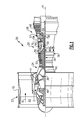
Figure 1 schematically illustrates agas turbine engine 20. Thegas turbine engine 20 is disclosed herein as a two-spool turbofan that generally incorporates afan section 22, a compressor section 24, acombustor section 26 and aturbine section 28. Alternative engines might include an augmentor section (not shown) among other systems or features. Thefan section 22 drives air along a bypass flow path B in a bypass duct defined within anacelle 15, while the compressor section 24 drives air along a core flow path C for compression and communication into thecombustor section 26 then expansion through theturbine section 28. Although depicted as a two-spool turbofan gas turbine engine in the disclosed non-limiting embodiment, it should be understood that the concepts described herein are not limited to use with two-spool turbofans as the teachings may be applied to other types of turbine engines including three-spool architectures. - The
exemplary engine 20 generally includes alow speed spool 30 and ahigh speed spool 32 mounted for rotation about an engine central longitudinal axis A relative to an enginestatic structure 36 viaseveral bearing systems 38. It should be understood thatvarious bearing systems 38 at various locations may alternatively or additionally be provided, and the location ofbearing systems 38 may be varied as appropriate to the application. - The
low speed spool 30 generally includes aninner shaft 40 that interconnects afan 42, a first (or low)pressure compressor 44 and a first (or low)pressure turbine 46. Theinner shaft 40 is connected to thefan 42 through a speed change mechanism, which in exemplarygas turbine engine 20 is illustrated as a gearedarchitecture 48 to drive thefan 42 at a lower speed than thelow speed spool 30. Thehigh speed spool 32 includes anouter shaft 50 that interconnects a second (or high)pressure compressor 52 and a second (or high)pressure turbine 54. Acombustor 56 is arranged inexemplary gas turbine 20 between thehigh pressure compressor 52 and thehigh pressure turbine 54. Amid-turbine frame 57 of the enginestatic structure 36 is arranged generally between thehigh pressure turbine 54 and thelow pressure turbine 46. Themid-turbine frame 57 further supports bearingsystems 38 in theturbine section 28. Theinner shaft 40 and theouter shaft 50 are concentric and rotate viabearing systems 38 about the engine central longitudinal axis A which is collinear with their longitudinal axes. - The core airflow is compressed by the
low pressure compressor 44 then thehigh pressure compressor 52, mixed and burned with fuel in thecombustor 56, then expanded over thehigh pressure turbine 54 andlow pressure turbine 46. Themid-turbine frame 57 includesairfoils 59 which are in the core airflow path C. Theturbines low speed spool 30 andhigh speed spool 32 in response to the expansion. It will be appreciated that each of the positions of thefan section 22, compressor section 24,combustor section 26,turbine section 28, and fandrive gear system 48 may be varied. For example,gear system 48 may be located aft ofcombustor section 26 or even aft ofturbine section 28, andfan section 22 may be positioned forward or aft of the location ofgear system 48. - The
engine 20 in one example is a high-bypass geared aircraft engine. In a further example, theengine 20 bypass ratio is greater than about six (6), with an example embodiment being greater than about ten (10), the gearedarchitecture 48 is an epicyclic gear train, such as a planetary gear system or other gear system, with a gear reduction ratio of greater than about 2.3 and thelow pressure turbine 46 has a pressure ratio that is greater than about five. In one disclosed embodiment, theengine 20 bypass ratio is greater than about ten (10:1), the fan diameter is significantly larger than that of thelow pressure compressor 44, and thelow pressure turbine 46 has a pressure ratio that is greater than about five 5:1.Low pressure turbine 46 pressure ratio is pressure measured prior to inlet oflow pressure turbine 46 as related to the pressure at the outlet of thelow pressure turbine 46 prior to an exhaust nozzle. The gearedarchitecture 48 may be an epicycle gear train, such as a planetary gear system or other gear system, with a gear reduction ratio of greater than about 2.3:1. It should be understood, however, that the above parameters are only exemplary of one embodiment of a geared architecture engine and that the present invention is applicable to other gas turbine engines including direct drive turbofans. - A significant amount of thrust is provided by the bypass flow B due to the high bypass ratio. The
fan section 22 of theengine 20 is designed for a particular flight condition -- typically cruise at about 0.8 Mach and about 35,000 feet. The flight condition of 0.8 Mach and 35,000 ft (10,668 meters), with the engine at its best fuel consumption - also known as "bucket cruise Thrust Specific Fuel Consumption ('TSFC')" - is the industry standard parameter of Ibm of fuel being burned divided by lbf of thrust the engine produces at that minimum point. "Low fan pressure ratio" is the pressure ratio across the fan blade alone, without a Fan Exit Guide Vane ("FEGV") system. The low fan pressure ratio as disclosed herein according to one non-limiting embodiment is less than about 1.45. "Low corrected fan tip speed" is the actual fan tip speed in ft/sec divided by an industry standard temperature correction of [(Tram °R) / (518.7 °R)]0.5. The "Low corrected fan tip speed" as disclosed herein according to one non-limiting embodiment is less than about 1150 ft / second (350.5 meters/second). -
Figure 2 illustrates anexample airfoil structure 60 including anairfoil 62, aplatform 64, and optionally aroot portion 66. In the illustrated example, theairfoil structure 60 is a turbine blade. However, theairfoil structure 60 could also be a vane or a compressor blade. Theairfoil structure 60 is configured to form a circumferential ring surrounding the engine axis A when jointed with additionalsimilar airfoil structures 60. In this disclosure, circumferential or circumferentially spaced is relative to a circumference surrounding the engine axis A of thegas turbine engine 20 unless otherwise specified. - The
airfoil 62 includes apressure side 72 and asuction side 74 separated by a leadingedge 76 and a trailingedge 78. Thepressure side 72 of theairfoil structure 60 is generally concave and the opposingsuction side 74 is generally convex. Afirst airfoil end 68 is rigidly attached to a radiallyouter side 70 of theplatform 64 and asecond airfoil end 69 is spaced from theplatform 64 forming a free end. However, thesecond airfoil end 69 could also include a radially outer platform or tip shroud. - In the illustrated example, the
airfoil 62 is formed integral with theplatform 64 such that theairfoil 62 and theplatform 64 form an integral or unitary piece. In another example, theairfoil 62 and theplatform 64 could be formed separately and then attached to each other. In this disclosure, radial or radial direction is relative to the engine axis A of thegas turbine engine 20 unless otherwise specified. - The radially
outer side 70 of theplatform 64 forms a radially inner boundary for fluid traveling over theairfoil structure 60. Theroot portion 66 extends radially inward from theplatform 64 to retain theairfoil structure 60 to a turbine rotor 79 (Figure 1 ). Theroot portion 66 is located on an opposite side of theplatform 64 from theairfoil 62 on a radiallyinner side 83. Theroot portion 66 includesribs 67 located on opposite sides of theroot portion 66 for engaging complimentary shaped receptacles on theturbine rotor 79 of thegas turbine engine 20. - As shown in
Figure 2 , a plurality of cooling holes 80 located along thepressure side 72 adjacent and upstream from the trailingedge 78 of theairfoil 62. The cooling holes 80 have a circular cross section and are surrounded by a relief cut 82 having a generally scalloped cross section. Although the cooling holes 80 in the illustrated example are circular, other shapes such as elliptical holes, oval holes, oblong holes, and race-track shaped holes could be used. The cooling holes 80 are radially spaced along theairfoil 62 and extend in a generally downstream direction. In the illustrated example, each of the cooling holes 80 is surrounded by one of the relief cuts 82. However, there could be coolingholes 80 that are not surrounded by one of the relief cuts 82. Although the relief cut 82 is elliptical in the illustrated example, other shapes could be used. Additionally, the major and minor axis of the elliptical shape of the relief cut 82 could vary between adjacent relief cuts 82. - The
adjacent relief cuts 82 are spaced from each other by abridge member 84. Thebridge member 84 includes a portion of theairfoil 62 that was not removed when therelief cuts 82 were formed. In the illustrated example, each of therelief cuts 82 have a generally identical shape and are evenly spaced from each other. However, a first pair ofadjacent relief cuts 82 could be spaced apart by a distance D1 and a second pair ofrelief cuts 82 could be spaced by a distance D2, which could be greater than or less than the distance D 1. - In one example, a relief cut distance between a radially outermost portion of a radially
outermost relief cut 82a and a radially innermost portion of a radiallyinnermost relief cut 82b is between 80% and 90% of a radial length of theairfoil 62. In another example, the relief cut distance is between 50% and 60% of the radial length of theairfoil 62. The relief cuts 82 are generally centered along theairfoil 62 such that a distance between the radiallyoutermost relief cut 82a and asecond airfoil end 69 is generally equal to a distance between the radiallyinnermost relief cut 82b and thefirst airfoil end 68. - As shown in
Figure 3 , theairfoil 62 includes internal cooling passages, such as a leadingedge cooling passage 88, anintermediate cooling passage 90, and a trailingedge cooling passage 92. The trialingedge cooling passage 92 feeds cooling air into thecooling hole 80 to create a cooling film over the relief cut 82 as the cooling air travels out of thecooling hole 80 and along thepressure side 72 towards the trialingedge 78. The relief cut 82 also includes a curvilinear profile. -
Figure 4 illustrates another example airfoil structure 60'. The airfoil structure 60' is similar to theairfoil structure 60 except where described below or shown in the Figures. A relief cut 82' extends continuously between adjacent cooling holes 80. - In the illustrated example, the relief cut 82' extends approximately 100% of the radial length of the
airfoil 62. In another example, the relief cut 82' extends approximately 80% to 90% of the radial length of the airfoil 62'. In yet another example, the relief cut 82' extends between approximately 50% and 60% of the radial length of the airfoil 62'. When the relief cut 82' extends less than 100% of the radial length of theairfoil 62, the relief cut 82' is generally centered along the airfoil 62' such that opposing edges of the relief cut 82' are equally spaced from thefirst airfoil end 68 and thesecond airfoil end 69, respectively. The relief cut 82' will have a generally curvilinear profile similar to the profile of the relief cut 82 shown inFigure 3 . - The
cooling hole 80 in theairfoil 62 is formed by drilling or machining thepressure side 72 adjacent the trialingedge 78. Once thecooling hole 80 is formed, either of therelief cuts 82, 82' can be formed by machining or milling. However, it is possible that therelief 82 could be formed prior to thecooling hole 80. When forming the relief cut 82 in a scallop shape, the relief cut 82 is generally centered on thecooling hole 80. When forming the relief cut 82', the relief cut 82' generally extends along a substantial portion of thepressure side 72 adjacent the trialingedge 78 and is connected between adjacent cooling holes 80. - Both of the
relief cuts 82, 82' remove anacute cross-section geometry 86 shown in hidden lines inFigure 3 formed by thecooling hole 80. By removing theacute cross-section geometry 86 from adjacent thecooling hole 80, the magnitude of stress concentration adjacent thecooling hole 80 is reduced. By reducing the stress concentrations adjacent the trialingedge 78, theairfoil 62 may be made of more brittle materials that could not previously sustain the stress concentrations around the cooling holes 80 with the acute cross-section geometry. - The relief cuts 82, 82' are also beneficial in cooling the trialing
edge 78 of theairfoil 62. In general, trailing edges of airfoils include a thicker wall dimension. The thicker walls of these trialing edges are more susceptible to operating at temperatures that are high then other portions of the airfoil. By varying the size of therelief cuts 82, 82' to remove additional material from the trailingedge 78 of theairfoil 62, the trailingedge 78 can be made thinner and be able to shed heat more easily. Additionally, the film of the cooling air exiting the cooling holes 80 reduces aerodynamic losses caused by the change in shape of thepressure side 72 from removing material to form therelief cuts 82, 82'. -
Figure 5 illustrates anotherexample airfoil structure 60". Theairfoil structure 60" is similar to theairfoil structure 60 except where described below or shown in the Figures. In the illustrated example, theairfoil structure 60" is a vane. - The
airfoil structure 60" includes a radiallyouter platform 65 located adjacent thesecond airfoil end 69. The radiallyouter platform 65 includes a radially inward facingsurface 67 that forms a radially outer boundary for fluid traveling over theairfoil structure 60". -
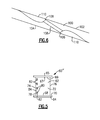
Figure 6 illustratesexample combustor wall 100 of thecombustor section 26. Thecombustor wall 100 includes aninterior surface 102 and an exteriorpressure side surface 104. Acooling hole 106 extends generally transverse to theinterior surface 102 and the exteriorpressure side surface 104. - When the
cooling hole 106 is formed in thecombustor wall 100, anacute cross-section geometry 108 is formed between the coolinghole 106 and theinterior surface 102 and the exteriorpressure side surface 104. Arelief cut 110 is made in both theinterior surface 102 and the exteriorpressure side surface 104 to remove theacute cross-section geometry 108. - By removing the acute cross-section geometry 180 from adjacent the
cooling hole 106, the magnitude of stress concentration adjacent thecooling hole 106 is reduced. By reducing the stress concentrations adjacent thecooling hole 106, theairfoil combustor wall 100 may be made of more brittle materials that could not previously sustain the stress concentrations around the cooling holes 106 with theacute cross-section geometry 108. - Although the different non-limiting embodiments are illustrated as having specific components, the embodiments of this disclosure are not limited to those particular combinations. It is possible to use some of the components or features from any of the non-limiting embodiments in combination with features or components from any of the other non-limiting embodiments.
- It should be understood that like reference numerals identify corresponding or similar elements throughout the several drawings. It should also be understood that although a particular component arrangement is disclosed and illustrated in these exemplary embodiments, other arrangements could also benefit from the teachings of this disclosure.
- The foregoing description shall be interpreted as illustrative and not in any limiting sense. A worker of ordinary skill in the art would understand that certain modifications could come within the scope of this disclosure. For these reasons, the following claim should be studied to determine the true scope and content of this disclosure.
Claims (14)
- A gas turbine engine component comprising:an exterior pressure side (72);a plurality of cooling holes (80; 106) located in the exterior pressure side (72); anda relief cut (82; 82'; 110) surrounding at least one of the plurality of cooling holes (80; 106).
- The component of claim 1, wherein the relief cut (82; 82'; 110) is elliptical and spaced from an adjacent relief cut (82; 82'; 110).
- The component of claim 1 or 2, wherein the component is an airfoil (62) and the plurality of cooling holes (80) are located adjacent a trailing edge (78) of the airfoil (62).
- The component of claim 3, wherein the plurality of cooling holes (80) are in communication with an internal cooling passage (88, 90, 92) in the airfoil (62).
- The component of claim 3 or 4, wherein the relief cut (82') is spaced inward from opposing radial ends (68, 69) of the airfoil (62) and is located upstream of the trailing edge (78).
- The component of any of claims 3 to 5, wherein the relief cut (82') extends between adjacent cooling holes (80) of the plurality of cooling holes (80) and the relief cut (82') extends between 80% and 90% of a length of the airfoil (62).
- The component of claim 6 wherein the relief cut (82') is generally centered along the airfoil (62).
- The component of claim 1 or 2, wherein the component is a combustor wall (100).
- A gas turbine engine (20) comprising a turbine section (28) configured to rotate about an axis of rotation (A) a combustor section (26); and wherein the component of any of claims 1 to 8 is located in at least one of the turbine section (28) and the combustor section (26).
- A method of forming a component comprising:forming a cooling hole (80; 106) in an exterior pressure side (72) of a component; andremoving a portion of the exterior pressure side (72) of the component to form a relief cut (82; 82'; 110).
- The method of claim 10, wherein the relief cut (82; 82'; 110) surrounds the cooling hole (80).
- The method of claim 10 or 11, further comprising reducing aerodynamic losses with a cooling film traveling over the relief cut (82; 82'; 110).
- The method of any of claims 10 to 12, further comprising varying an amount of material removed by the relief cut (82; 82'; 110) to control heat transfer in the trailing edge (78) of the component.
- The method of any of claims 10 to 13, further comprising removing an acute cross-section geometry (86) adjacent the cooling hole (80; 106) when forming the relief cut (82; 82'; 110).
Applications Claiming Priority (1)
| Application Number | Priority Date | Filing Date | Title |
|---|---|---|---|
| US201462065953P | 2014-10-20 | 2014-10-20 |
Publications (2)
| Publication Number | Publication Date |
|---|---|
| EP3012408A1 true EP3012408A1 (en) | 2016-04-27 |
| EP3012408B1 EP3012408B1 (en) | 2019-02-27 |
Family
ID=54337177
Family Applications (1)
| Application Number | Title | Priority Date | Filing Date |
|---|---|---|---|
| EP15190484.4A Active EP3012408B1 (en) | 2014-10-20 | 2015-10-20 | Gas turbine engine component with combustor wall having cooling hole |
Country Status (2)
| Country | Link |
|---|---|
| US (1) | US11280214B2 (en) |
| EP (1) | EP3012408B1 (en) |
Families Citing this family (6)
| Publication number | Priority date | Publication date | Assignee | Title |
|---|---|---|---|---|
| FR3039199B1 (en) * | 2015-07-20 | 2019-12-13 | Safran Helicopter Engines | BLADE OF HIGH PRESSURE DISTRIBUTOR WITH A VARIABLE GEOMETRY INSERT |
| KR102755150B1 (en) * | 2021-11-01 | 2025-01-14 | 두산에너빌리티 주식회사 | Airfoil and Gas turbine comprising the same |
| US11840346B2 (en) | 2022-03-28 | 2023-12-12 | Pratt & Whitney Canada Corp. | Strut for aircraft engine |
| US12540581B2 (en) | 2022-12-30 | 2026-02-03 | Ge Vernova Infrastructure Technology Llc | System and method having fluid injectors for isothermal expansion in turbine stage of gas turbine engine |
| US11971170B1 (en) * | 2022-12-30 | 2024-04-30 | Ge Infrastructure Technology Llc | System and method having flame stabilizers for isothermal expansion in turbine stage of gas turbine engine |
| US11891949B1 (en) | 2022-12-30 | 2024-02-06 | Ge Infrastructure Technology Llc | System and method having multi-fluid injectors for isothermal expansion in turbine stage of gas turbine engine |
Citations (12)
| Publication number | Priority date | Publication date | Assignee | Title |
|---|---|---|---|---|
| US4229140A (en) * | 1972-11-28 | 1980-10-21 | Rolls-Royce (1971) Ltd. | Turbine blade |
| WO1988010017A1 (en) * | 1987-06-01 | 1988-12-15 | Technical Manufacturing Systems, Inc. | Electro-discharge machining electrode and method of forming |
| US6155778A (en) * | 1998-12-30 | 2000-12-05 | General Electric Company | Recessed turbine shroud |
| EP1262631A2 (en) * | 2001-05-21 | 2002-12-04 | United Technologies Corporation | Film cooled blade or vane |
| DE10244199A1 (en) * | 2002-09-23 | 2004-04-01 | Alstom (Switzerland) Ltd. | Device for supplying secondary fluid to transsonic primary flow e.g. for supplying cooling air for film cooling in turbine plant |
| EP1726782A2 (en) * | 2005-05-27 | 2006-11-29 | United Technologies Corporation | Turbine blade trailing edge construction |
| EP1813365A1 (en) * | 2006-01-27 | 2007-08-01 | Snecma | Method of manufacturing a turbomachine part comprising cooling air outlets |
| US20100183429A1 (en) * | 2009-01-19 | 2010-07-22 | George Liang | Turbine blade with multiple trailing edge cooling slots |
| US20100192588A1 (en) * | 2009-02-03 | 2010-08-05 | Rolls-Royce Deutschland Ltd & Co Kg | Method for the provision of a cooling-air opening in a wall of a gas-turbine combustion chamber as well as a combustion-chamber wall produced in accordance with this method |
| EP2557270A2 (en) * | 2011-08-08 | 2013-02-13 | United Technologies Corporation | Airfoil including trench with contoured surface |
| EP2592229A2 (en) * | 2011-11-09 | 2013-05-15 | General Electric Company | Film hole trench |
| US20140271131A1 (en) * | 2013-03-13 | 2014-09-18 | Rolls-Royce Corporation | Trenched cooling hole arrangement for a ceramic matrix composite vane |
Family Cites Families (37)
| Publication number | Priority date | Publication date | Assignee | Title |
|---|---|---|---|---|
| US2785878A (en) * | 1953-09-16 | 1957-03-19 | Earl W Conrad | Porous walled conduit for fluid cooling |
| US3584972A (en) * | 1966-02-09 | 1971-06-15 | Gen Motors Corp | Laminated porous metal |
| US4025226A (en) | 1975-10-03 | 1977-05-24 | United Technologies Corporation | Air cooled turbine vane |
| US4303374A (en) * | 1978-12-15 | 1981-12-01 | General Electric Company | Film cooled airfoil body |
| US4601638A (en) * | 1984-12-21 | 1986-07-22 | United Technologies Corporation | Airfoil trailing edge cooling arrangement |
| US4672727A (en) * | 1985-12-23 | 1987-06-16 | United Technologies Corporation | Method of fabricating film cooling slot in a hollow airfoil |
| US4737613A (en) * | 1987-08-24 | 1988-04-12 | United Technologies Corporation | Laser machining method |
| GB2227965B (en) * | 1988-10-12 | 1993-02-10 | Rolls Royce Plc | Apparatus for drilling a shaped hole in a workpiece |
| US5402159A (en) | 1990-03-26 | 1995-03-28 | Brother Kogyo Kabushiki Kaisha | Piezoelectric ink jet printer using laminated piezoelectric actuator |
| US5142871A (en) * | 1991-01-22 | 1992-09-01 | General Electric Company | Combustor dome plate support having uniform thickness arcuate apex with circumferentially spaced coolant apertures |
| US5660525A (en) * | 1992-10-29 | 1997-08-26 | General Electric Company | Film cooled slotted wall |
| US5651662A (en) * | 1992-10-29 | 1997-07-29 | General Electric Company | Film cooled wall |
| US5419681A (en) * | 1993-01-25 | 1995-05-30 | General Electric Company | Film cooled wall |
| US5503529A (en) * | 1994-12-08 | 1996-04-02 | General Electric Company | Turbine blade having angled ejection slot |
| US5458461A (en) * | 1994-12-12 | 1995-10-17 | General Electric Company | Film cooled slotted wall |
| GB9821639D0 (en) * | 1998-10-06 | 1998-11-25 | Rolls Royce Plc | Coolant passages for gas turbine components |
| US6102658A (en) | 1998-12-22 | 2000-08-15 | United Technologies Corporation | Trailing edge cooling apparatus for a gas turbine airfoil |
| US6213714B1 (en) * | 1999-06-29 | 2001-04-10 | Allison Advanced Development Company | Cooled airfoil |
| US6234755B1 (en) * | 1999-10-04 | 2001-05-22 | General Electric Company | Method for improving the cooling effectiveness of a gaseous coolant stream, and related articles of manufacture |
| US6422819B1 (en) * | 1999-12-09 | 2002-07-23 | General Electric Company | Cooled airfoil for gas turbine engine and method of making the same |
| US6270317B1 (en) * | 1999-12-18 | 2001-08-07 | General Electric Company | Turbine nozzle with sloped film cooling |
| US6573474B1 (en) * | 2000-10-18 | 2003-06-03 | Chromalloy Gas Turbine Corporation | Process for drilling holes through a thermal barrier coating |
| DE50306044D1 (en) | 2003-09-05 | 2007-02-01 | Siemens Ag | Shovel of a turbine |
| US7255534B2 (en) * | 2004-07-02 | 2007-08-14 | Siemens Power Generation, Inc. | Gas turbine vane with integral cooling system |
| US7246999B2 (en) | 2004-10-06 | 2007-07-24 | General Electric Company | Stepped outlet turbine airfoil |
| FR2887287B1 (en) * | 2005-06-21 | 2007-09-21 | Snecma Moteurs Sa | COOLING CIRCUITS FOR MOBILE TURBINE DRIVE |
| US7296973B2 (en) * | 2005-12-05 | 2007-11-20 | General Electric Company | Parallel serpentine cooled blade |
| GB0603705D0 (en) * | 2006-02-24 | 2006-04-05 | Rolls Royce Plc | Aerofoils |
| US8579590B2 (en) | 2006-05-18 | 2013-11-12 | Wood Group Heavy Industrial Turbines Ag | Turbomachinery blade having a platform relief hole, platform cooling holes, and trailing edge cutback |
| US7553534B2 (en) * | 2006-08-29 | 2009-06-30 | General Electric Company | Film cooled slotted wall and method of making the same |
| US8105030B2 (en) * | 2008-08-14 | 2012-01-31 | United Technologies Corporation | Cooled airfoils and gas turbine engine systems involving such airfoils |
| US8057182B2 (en) * | 2008-11-21 | 2011-11-15 | General Electric Company | Metered cooling slots for turbine blades |
| US7980821B1 (en) | 2008-12-15 | 2011-07-19 | Florida Turbine Technologies, Inc. | Turbine blade with trailing edge cooling |
| US8608443B2 (en) * | 2010-06-11 | 2013-12-17 | Siemens Energy, Inc. | Film cooled component wall in a turbine engine |
| US9028207B2 (en) * | 2010-09-23 | 2015-05-12 | Siemens Energy, Inc. | Cooled component wall in a turbine engine |
| US8261810B1 (en) | 2012-01-24 | 2012-09-11 | Florida Turbine Technologies, Inc. | Turbine airfoil ceramic core with strain relief slot |
| US9567860B2 (en) | 2012-11-27 | 2017-02-14 | General Electric Company | Fixture for an airfoil shroud and method for modifying an airfoil shroud |
-
2015
- 2015-10-08 US US14/878,555 patent/US11280214B2/en active Active
- 2015-10-20 EP EP15190484.4A patent/EP3012408B1/en active Active
Patent Citations (12)
| Publication number | Priority date | Publication date | Assignee | Title |
|---|---|---|---|---|
| US4229140A (en) * | 1972-11-28 | 1980-10-21 | Rolls-Royce (1971) Ltd. | Turbine blade |
| WO1988010017A1 (en) * | 1987-06-01 | 1988-12-15 | Technical Manufacturing Systems, Inc. | Electro-discharge machining electrode and method of forming |
| US6155778A (en) * | 1998-12-30 | 2000-12-05 | General Electric Company | Recessed turbine shroud |
| EP1262631A2 (en) * | 2001-05-21 | 2002-12-04 | United Technologies Corporation | Film cooled blade or vane |
| DE10244199A1 (en) * | 2002-09-23 | 2004-04-01 | Alstom (Switzerland) Ltd. | Device for supplying secondary fluid to transsonic primary flow e.g. for supplying cooling air for film cooling in turbine plant |
| EP1726782A2 (en) * | 2005-05-27 | 2006-11-29 | United Technologies Corporation | Turbine blade trailing edge construction |
| EP1813365A1 (en) * | 2006-01-27 | 2007-08-01 | Snecma | Method of manufacturing a turbomachine part comprising cooling air outlets |
| US20100183429A1 (en) * | 2009-01-19 | 2010-07-22 | George Liang | Turbine blade with multiple trailing edge cooling slots |
| US20100192588A1 (en) * | 2009-02-03 | 2010-08-05 | Rolls-Royce Deutschland Ltd & Co Kg | Method for the provision of a cooling-air opening in a wall of a gas-turbine combustion chamber as well as a combustion-chamber wall produced in accordance with this method |
| EP2557270A2 (en) * | 2011-08-08 | 2013-02-13 | United Technologies Corporation | Airfoil including trench with contoured surface |
| EP2592229A2 (en) * | 2011-11-09 | 2013-05-15 | General Electric Company | Film hole trench |
| US20140271131A1 (en) * | 2013-03-13 | 2014-09-18 | Rolls-Royce Corporation | Trenched cooling hole arrangement for a ceramic matrix composite vane |
Also Published As
| Publication number | Publication date |
|---|---|
| US20160108755A1 (en) | 2016-04-21 |
| EP3012408B1 (en) | 2019-02-27 |
| US11280214B2 (en) | 2022-03-22 |
Similar Documents
| Publication | Publication Date | Title |
|---|---|---|
| US11286790B2 (en) | Cooling passages for gas turbine engine component | |
| EP2942488B1 (en) | Blade for a gas turbine engine, gas turbine engine and method of cooling a blade for a gas turbine engine | |
| US10612392B2 (en) | Gas turbine engine component with conformal fillet cooling path | |
| US10502066B2 (en) | Turbine engine component including an axially aligned skin core passage interrupted by a pedestal | |
| EP3012408B1 (en) | Gas turbine engine component with combustor wall having cooling hole | |
| EP2993304B1 (en) | Gas turbine engine component with film cooling hole | |
| EP3091184A1 (en) | Turbine airfoil leading edge cooling | |
| EP2977555A1 (en) | Airfoil platform impingement cooling holes | |
| EP3061910A1 (en) | Gas turbine engine airfoil and corresponding method of forming | |
| EP4116543A1 (en) | Endwall contouring for airfoil rows with varying airfoil geometries | |
| US20140219813A1 (en) | Gas turbine engine serpentine cooling passage | |
| EP3045666B1 (en) | Airfoil platform with cooling feed orifices | |
| US9988910B2 (en) | Staggered core printout | |
| EP3101236A1 (en) | Trailing edge platform seals | |
| EP2993300B1 (en) | Gas turbine engine airfoil structure | |
| EP2961964B1 (en) | Gas turbine engine component and corresponding method of manufacturing an aperture | |
| EP3406851A1 (en) | Component for a gas turbine engine and method of forming a core assembly | |
| EP2942486B1 (en) | Gas turbine engine airfoil cooling passage configuration | |
| EP3550105B1 (en) | Gas turbine engine rotor disk |
Legal Events
| Date | Code | Title | Description |
|---|---|---|---|
| PUAI | Public reference made under article 153(3) epc to a published international application that has entered the european phase |
Free format text: ORIGINAL CODE: 0009012 |
|
| AK | Designated contracting states |
Kind code of ref document: A1 Designated state(s): AL AT BE BG CH CY CZ DE DK EE ES FI FR GB GR HR HU IE IS IT LI LT LU LV MC MK MT NL NO PL PT RO RS SE SI SK SM TR |
|
| AX | Request for extension of the european patent |
Extension state: BA ME |
|
| RAP1 | Party data changed (applicant data changed or rights of an application transferred) |
Owner name: UNITED TECHNOLOGIES CORPORATION |
|
| STAA | Information on the status of an ep patent application or granted ep patent |
Free format text: STATUS: REQUEST FOR EXAMINATION WAS MADE |
|
| 17P | Request for examination filed |
Effective date: 20161027 |
|
| RBV | Designated contracting states (corrected) |
Designated state(s): AL AT BE BG CH CY CZ DE DK EE ES FI FR GB GR HR HU IE IS IT LI LT LU LV MC MK MT NL NO PL PT RO RS SE SI SK SM TR |
|
| GRAP | Despatch of communication of intention to grant a patent |
Free format text: ORIGINAL CODE: EPIDOSNIGR1 |
|
| STAA | Information on the status of an ep patent application or granted ep patent |
Free format text: STATUS: GRANT OF PATENT IS INTENDED |
|
| INTG | Intention to grant announced |
Effective date: 20180906 |
|
| GRAS | Grant fee paid |
Free format text: ORIGINAL CODE: EPIDOSNIGR3 |
|
| GRAA | (expected) grant |
Free format text: ORIGINAL CODE: 0009210 |
|
| STAA | Information on the status of an ep patent application or granted ep patent |
Free format text: STATUS: THE PATENT HAS BEEN GRANTED |
|
| AK | Designated contracting states |
Kind code of ref document: B1 Designated state(s): AL AT BE BG CH CY CZ DE DK EE ES FI FR GB GR HR HU IE IS IT LI LT LU LV MC MK MT NL NO PL PT RO RS SE SI SK SM TR |
|
| REG | Reference to a national code |
Ref country code: GB Ref legal event code: FG4D |
|
| REG | Reference to a national code |
Ref country code: CH Ref legal event code: EP |
|
| REG | Reference to a national code |
Ref country code: AT Ref legal event code: REF Ref document number: 1101629 Country of ref document: AT Kind code of ref document: T Effective date: 20190315 |
|
| REG | Reference to a national code |
Ref country code: IE Ref legal event code: FG4D |
|
| REG | Reference to a national code |
Ref country code: DE Ref legal event code: R096 Ref document number: 602015025264 Country of ref document: DE |
|
| REG | Reference to a national code |
Ref country code: NL Ref legal event code: MP Effective date: 20190227 |
|
| REG | Reference to a national code |
Ref country code: LT Ref legal event code: MG4D |
|
| PG25 | Lapsed in a contracting state [announced via postgrant information from national office to epo] |
Ref country code: LT Free format text: LAPSE BECAUSE OF FAILURE TO SUBMIT A TRANSLATION OF THE DESCRIPTION OR TO PAY THE FEE WITHIN THE PRESCRIBED TIME-LIMIT Effective date: 20190227 Ref country code: SE Free format text: LAPSE BECAUSE OF FAILURE TO SUBMIT A TRANSLATION OF THE DESCRIPTION OR TO PAY THE FEE WITHIN THE PRESCRIBED TIME-LIMIT Effective date: 20190227 Ref country code: NO Free format text: LAPSE BECAUSE OF FAILURE TO SUBMIT A TRANSLATION OF THE DESCRIPTION OR TO PAY THE FEE WITHIN THE PRESCRIBED TIME-LIMIT Effective date: 20190527 Ref country code: PT Free format text: LAPSE BECAUSE OF FAILURE TO SUBMIT A TRANSLATION OF THE DESCRIPTION OR TO PAY THE FEE WITHIN THE PRESCRIBED TIME-LIMIT Effective date: 20190627 Ref country code: FI Free format text: LAPSE BECAUSE OF FAILURE TO SUBMIT A TRANSLATION OF THE DESCRIPTION OR TO PAY THE FEE WITHIN THE PRESCRIBED TIME-LIMIT Effective date: 20190227 |
|
| PG25 | Lapsed in a contracting state [announced via postgrant information from national office to epo] |
Ref country code: LV Free format text: LAPSE BECAUSE OF FAILURE TO SUBMIT A TRANSLATION OF THE DESCRIPTION OR TO PAY THE FEE WITHIN THE PRESCRIBED TIME-LIMIT Effective date: 20190227 Ref country code: IS Free format text: LAPSE BECAUSE OF FAILURE TO SUBMIT A TRANSLATION OF THE DESCRIPTION OR TO PAY THE FEE WITHIN THE PRESCRIBED TIME-LIMIT Effective date: 20190627 Ref country code: RS Free format text: LAPSE BECAUSE OF FAILURE TO SUBMIT A TRANSLATION OF THE DESCRIPTION OR TO PAY THE FEE WITHIN THE PRESCRIBED TIME-LIMIT Effective date: 20190227 Ref country code: BG Free format text: LAPSE BECAUSE OF FAILURE TO SUBMIT A TRANSLATION OF THE DESCRIPTION OR TO PAY THE FEE WITHIN THE PRESCRIBED TIME-LIMIT Effective date: 20190527 Ref country code: HR Free format text: LAPSE BECAUSE OF FAILURE TO SUBMIT A TRANSLATION OF THE DESCRIPTION OR TO PAY THE FEE WITHIN THE PRESCRIBED TIME-LIMIT Effective date: 20190227 Ref country code: GR Free format text: LAPSE BECAUSE OF FAILURE TO SUBMIT A TRANSLATION OF THE DESCRIPTION OR TO PAY THE FEE WITHIN THE PRESCRIBED TIME-LIMIT Effective date: 20190528 Ref country code: NL Free format text: LAPSE BECAUSE OF FAILURE TO SUBMIT A TRANSLATION OF THE DESCRIPTION OR TO PAY THE FEE WITHIN THE PRESCRIBED TIME-LIMIT Effective date: 20190227 |
|
| REG | Reference to a national code |
Ref country code: AT Ref legal event code: MK05 Ref document number: 1101629 Country of ref document: AT Kind code of ref document: T Effective date: 20190227 |
|
| PG25 | Lapsed in a contracting state [announced via postgrant information from national office to epo] |
Ref country code: ES Free format text: LAPSE BECAUSE OF FAILURE TO SUBMIT A TRANSLATION OF THE DESCRIPTION OR TO PAY THE FEE WITHIN THE PRESCRIBED TIME-LIMIT Effective date: 20190227 Ref country code: AL Free format text: LAPSE BECAUSE OF FAILURE TO SUBMIT A TRANSLATION OF THE DESCRIPTION OR TO PAY THE FEE WITHIN THE PRESCRIBED TIME-LIMIT Effective date: 20190227 Ref country code: SK Free format text: LAPSE BECAUSE OF FAILURE TO SUBMIT A TRANSLATION OF THE DESCRIPTION OR TO PAY THE FEE WITHIN THE PRESCRIBED TIME-LIMIT Effective date: 20190227 Ref country code: RO Free format text: LAPSE BECAUSE OF FAILURE TO SUBMIT A TRANSLATION OF THE DESCRIPTION OR TO PAY THE FEE WITHIN THE PRESCRIBED TIME-LIMIT Effective date: 20190227 Ref country code: CZ Free format text: LAPSE BECAUSE OF FAILURE TO SUBMIT A TRANSLATION OF THE DESCRIPTION OR TO PAY THE FEE WITHIN THE PRESCRIBED TIME-LIMIT Effective date: 20190227 Ref country code: DK Free format text: LAPSE BECAUSE OF FAILURE TO SUBMIT A TRANSLATION OF THE DESCRIPTION OR TO PAY THE FEE WITHIN THE PRESCRIBED TIME-LIMIT Effective date: 20190227 Ref country code: IT Free format text: LAPSE BECAUSE OF FAILURE TO SUBMIT A TRANSLATION OF THE DESCRIPTION OR TO PAY THE FEE WITHIN THE PRESCRIBED TIME-LIMIT Effective date: 20190227 Ref country code: EE Free format text: LAPSE BECAUSE OF FAILURE TO SUBMIT A TRANSLATION OF THE DESCRIPTION OR TO PAY THE FEE WITHIN THE PRESCRIBED TIME-LIMIT Effective date: 20190227 |
|
| REG | Reference to a national code |
Ref country code: DE Ref legal event code: R097 Ref document number: 602015025264 Country of ref document: DE |
|
| PG25 | Lapsed in a contracting state [announced via postgrant information from national office to epo] |
Ref country code: PL Free format text: LAPSE BECAUSE OF FAILURE TO SUBMIT A TRANSLATION OF THE DESCRIPTION OR TO PAY THE FEE WITHIN THE PRESCRIBED TIME-LIMIT Effective date: 20190227 Ref country code: SM Free format text: LAPSE BECAUSE OF FAILURE TO SUBMIT A TRANSLATION OF THE DESCRIPTION OR TO PAY THE FEE WITHIN THE PRESCRIBED TIME-LIMIT Effective date: 20190227 |
|
| PG25 | Lapsed in a contracting state [announced via postgrant information from national office to epo] |
Ref country code: AT Free format text: LAPSE BECAUSE OF FAILURE TO SUBMIT A TRANSLATION OF THE DESCRIPTION OR TO PAY THE FEE WITHIN THE PRESCRIBED TIME-LIMIT Effective date: 20190227 |
|
| PLBE | No opposition filed within time limit |
Free format text: ORIGINAL CODE: 0009261 |
|
| STAA | Information on the status of an ep patent application or granted ep patent |
Free format text: STATUS: NO OPPOSITION FILED WITHIN TIME LIMIT |
|
| 26N | No opposition filed |
Effective date: 20191128 |
|
| PG25 | Lapsed in a contracting state [announced via postgrant information from national office to epo] |
Ref country code: SI Free format text: LAPSE BECAUSE OF FAILURE TO SUBMIT A TRANSLATION OF THE DESCRIPTION OR TO PAY THE FEE WITHIN THE PRESCRIBED TIME-LIMIT Effective date: 20190227 |
|
| PG25 | Lapsed in a contracting state [announced via postgrant information from national office to epo] |
Ref country code: TR Free format text: LAPSE BECAUSE OF FAILURE TO SUBMIT A TRANSLATION OF THE DESCRIPTION OR TO PAY THE FEE WITHIN THE PRESCRIBED TIME-LIMIT Effective date: 20190227 |
|
| PG25 | Lapsed in a contracting state [announced via postgrant information from national office to epo] |
Ref country code: MC Free format text: LAPSE BECAUSE OF FAILURE TO SUBMIT A TRANSLATION OF THE DESCRIPTION OR TO PAY THE FEE WITHIN THE PRESCRIBED TIME-LIMIT Effective date: 20190227 |
|
| REG | Reference to a national code |
Ref country code: CH Ref legal event code: PL |
|
| PG25 | Lapsed in a contracting state [announced via postgrant information from national office to epo] |
Ref country code: LI Free format text: LAPSE BECAUSE OF NON-PAYMENT OF DUE FEES Effective date: 20191031 Ref country code: CH Free format text: LAPSE BECAUSE OF NON-PAYMENT OF DUE FEES Effective date: 20191031 Ref country code: LU Free format text: LAPSE BECAUSE OF NON-PAYMENT OF DUE FEES Effective date: 20191020 |
|
| REG | Reference to a national code |
Ref country code: BE Ref legal event code: MM Effective date: 20191031 |
|
| PG25 | Lapsed in a contracting state [announced via postgrant information from national office to epo] |
Ref country code: BE Free format text: LAPSE BECAUSE OF NON-PAYMENT OF DUE FEES Effective date: 20191031 |
|
| PG25 | Lapsed in a contracting state [announced via postgrant information from national office to epo] |
Ref country code: IE Free format text: LAPSE BECAUSE OF NON-PAYMENT OF DUE FEES Effective date: 20191020 |
|
| PG25 | Lapsed in a contracting state [announced via postgrant information from national office to epo] |
Ref country code: CY Free format text: LAPSE BECAUSE OF FAILURE TO SUBMIT A TRANSLATION OF THE DESCRIPTION OR TO PAY THE FEE WITHIN THE PRESCRIBED TIME-LIMIT Effective date: 20190227 |
|
| PG25 | Lapsed in a contracting state [announced via postgrant information from national office to epo] |
Ref country code: MT Free format text: LAPSE BECAUSE OF FAILURE TO SUBMIT A TRANSLATION OF THE DESCRIPTION OR TO PAY THE FEE WITHIN THE PRESCRIBED TIME-LIMIT Effective date: 20190227 Ref country code: HU Free format text: LAPSE BECAUSE OF FAILURE TO SUBMIT A TRANSLATION OF THE DESCRIPTION OR TO PAY THE FEE WITHIN THE PRESCRIBED TIME-LIMIT; INVALID AB INITIO Effective date: 20151020 |
|
| PG25 | Lapsed in a contracting state [announced via postgrant information from national office to epo] |
Ref country code: MK Free format text: LAPSE BECAUSE OF FAILURE TO SUBMIT A TRANSLATION OF THE DESCRIPTION OR TO PAY THE FEE WITHIN THE PRESCRIBED TIME-LIMIT Effective date: 20190227 |
|
| REG | Reference to a national code |
Ref country code: DE Ref legal event code: R081 Ref document number: 602015025264 Country of ref document: DE Owner name: RAYTHEON TECHNOLOGIES CORPORATION (N.D.GES.D.S, US Free format text: FORMER OWNER: UNITED TECHNOLOGIES CORPORATION, FARMINGTON, CONN., US Ref country code: DE Ref legal event code: R081 Ref document number: 602015025264 Country of ref document: DE Owner name: RTX CORPORATION (N.D.GES.D. STAATES DELAWARE),, US Free format text: FORMER OWNER: UNITED TECHNOLOGIES CORPORATION, FARMINGTON, CONN., US |
|
| P01 | Opt-out of the competence of the unified patent court (upc) registered |
Effective date: 20230520 |
|
| PGFP | Annual fee paid to national office [announced via postgrant information from national office to epo] |
Ref country code: GB Payment date: 20250923 Year of fee payment: 11 |
|
| PGFP | Annual fee paid to national office [announced via postgrant information from national office to epo] |
Ref country code: FR Payment date: 20250924 Year of fee payment: 11 |
|
| REG | Reference to a national code |
Ref country code: DE Ref legal event code: R081 Ref document number: 602015025264 Country of ref document: DE Owner name: RTX CORPORATION (N.D.GES.D. STAATES DELAWARE),, US Free format text: FORMER OWNER: RAYTHEON TECHNOLOGIES CORPORATION (N.D.GES.D.STAATES DELAWARE), ARLINGTON, VA, US |
|
| PGFP | Annual fee paid to national office [announced via postgrant information from national office to epo] |
Ref country code: DE Payment date: 20250923 Year of fee payment: 11 |