EP3012402A1 - Flussprofilmodellierung für bohrlöcher - Google Patents
Flussprofilmodellierung für bohrlöcher Download PDFInfo
- Publication number
- EP3012402A1 EP3012402A1 EP15196092.9A EP15196092A EP3012402A1 EP 3012402 A1 EP3012402 A1 EP 3012402A1 EP 15196092 A EP15196092 A EP 15196092A EP 3012402 A1 EP3012402 A1 EP 3012402A1
- Authority
- EP
- European Patent Office
- Prior art keywords
- permeability
- well
- measure
- data
- viscosity
- Prior art date
- Legal status (The legal status is an assumption and is not a legal conclusion. Google has not performed a legal analysis and makes no representation as to the accuracy of the status listed.)
- Granted
Links
- 230000015572 biosynthetic process Effects 0.000 claims description 174
- 230000035699 permeability Effects 0.000 claims description 86
- 238000012545 processing Methods 0.000 claims description 75
- 239000012530 fluid Substances 0.000 claims description 53
- 238000000034 method Methods 0.000 claims description 32
- 238000013500 data storage Methods 0.000 claims description 25
- 238000005755 formation reaction Methods 0.000 description 154
- 238000005259 measurement Methods 0.000 description 60
- XLYOFNOQVPJJNP-UHFFFAOYSA-N water Substances O XLYOFNOQVPJJNP-UHFFFAOYSA-N 0.000 description 19
- 230000006870 function Effects 0.000 description 17
- 238000004519 manufacturing process Methods 0.000 description 16
- 238000005553 drilling Methods 0.000 description 13
- 230000001186 cumulative effect Effects 0.000 description 12
- 238000005481 NMR spectroscopy Methods 0.000 description 8
- 238000010586 diagram Methods 0.000 description 5
- 229930195733 hydrocarbon Natural products 0.000 description 5
- 230000008569 process Effects 0.000 description 5
- 239000004215 Carbon black (E152) Substances 0.000 description 4
- 150000002430 hydrocarbons Chemical class 0.000 description 4
- 238000002347 injection Methods 0.000 description 4
- 239000007924 injection Substances 0.000 description 4
- 238000004088 simulation Methods 0.000 description 4
- 238000012986 modification Methods 0.000 description 3
- 230000004048 modification Effects 0.000 description 3
- 239000011435 rock Substances 0.000 description 3
- 230000008901 benefit Effects 0.000 description 2
- 238000004590 computer program Methods 0.000 description 2
- 238000005070 sampling Methods 0.000 description 2
- 230000000638 stimulation Effects 0.000 description 2
- 238000004458 analytical method Methods 0.000 description 1
- 230000006399 behavior Effects 0.000 description 1
- 239000006227 byproduct Substances 0.000 description 1
- 238000004891 communication Methods 0.000 description 1
- 238000005094 computer simulation Methods 0.000 description 1
- 230000001934 delay Effects 0.000 description 1
- 230000000694 effects Effects 0.000 description 1
- 239000008398 formation water Substances 0.000 description 1
- 230000005251 gamma ray Effects 0.000 description 1
- 125000001183 hydrocarbyl group Chemical group 0.000 description 1
- 238000011065 in-situ storage Methods 0.000 description 1
- 230000006698 induction Effects 0.000 description 1
- 238000009533 lab test Methods 0.000 description 1
- 238000011022 operating instruction Methods 0.000 description 1
- 230000003287 optical effect Effects 0.000 description 1
- 230000002093 peripheral effect Effects 0.000 description 1
- 238000007781 pre-processing Methods 0.000 description 1
- 230000004044 response Effects 0.000 description 1
- 238000003860 storage Methods 0.000 description 1
- 238000012546 transfer Methods 0.000 description 1
Images


Classifications
-
- E—FIXED CONSTRUCTIONS
- E21—EARTH OR ROCK DRILLING; MINING
- E21B—EARTH OR ROCK DRILLING; OBTAINING OIL, GAS, WATER, SOLUBLE OR MELTABLE MATERIALS OR A SLURRY OF MINERALS FROM WELLS
- E21B47/00—Survey of boreholes or wells
- E21B47/12—Means for transmitting measuring-signals or control signals from the well to the surface, or from the surface to the well, e.g. for logging while drilling
-
- G—PHYSICS
- G01—MEASURING; TESTING
- G01V—GEOPHYSICS; GRAVITATIONAL MEASUREMENTS; DETECTING MASSES OR OBJECTS; TAGS
- G01V11/00—Prospecting or detecting by methods combining techniques covered by two or more of main groups G01V1/00 - G01V9/00
-
- E—FIXED CONSTRUCTIONS
- E21—EARTH OR ROCK DRILLING; MINING
- E21B—EARTH OR ROCK DRILLING; OBTAINING OIL, GAS, WATER, SOLUBLE OR MELTABLE MATERIALS OR A SLURRY OF MINERALS FROM WELLS
- E21B43/00—Methods or apparatus for obtaining oil, gas, water, soluble or meltable materials or a slurry of minerals from wells
-
- E—FIXED CONSTRUCTIONS
- E21—EARTH OR ROCK DRILLING; MINING
- E21B—EARTH OR ROCK DRILLING; OBTAINING OIL, GAS, WATER, SOLUBLE OR MELTABLE MATERIALS OR A SLURRY OF MINERALS FROM WELLS
- E21B47/00—Survey of boreholes or wells
-
- E—FIXED CONSTRUCTIONS
- E21—EARTH OR ROCK DRILLING; MINING
- E21B—EARTH OR ROCK DRILLING; OBTAINING OIL, GAS, WATER, SOLUBLE OR MELTABLE MATERIALS OR A SLURRY OF MINERALS FROM WELLS
- E21B47/00—Survey of boreholes or wells
- E21B47/10—Locating fluid leaks, intrusions or movements
Definitions
- the present invention relates to computerized simulation of hydrocarbon reservoirs in the earth, and in particular to forming models of flow profiles of fluids in wells in subsurface earth formations based on data obtained from well logging tools and laboratory data.
- a well logging tool known as a production logging tool (or PLT) was often used for evaluating wells to determine the flow profiles of the formations where the wells were located.
- PLT production logging tool
- a production logging tool run was expensive and time consuming.
- selection among wells in a reservoir or formation of wells as candidates for a production logging tool run had to be made on the basis of data from other, earlier logs together with estimates and intuition based on subjective prior experience.
- analysis of the subsurface formation flow was based on data available from the other, earlier logging tool runs.
- the present invention provides a new and improved computer implemented method of obtaining a measure of transmissibility of fluid in a subsurface formation at a location in a well bore.
- a measure of the thickness of the formation is determined based on measurements obtained from a well logging tool, and obtaining a measure of the permeability of the formation is obtained based on logging measurements obtained from a well logging tool.
- a measure of the viscosity of the formation fluid is also obtained based on logging measurements obtained from a well logging tool.
- the transmissibility of fluid in the subsurface formation at the location in the formation is obtained based on the obtained measures of the thickness, permeability and viscosity.
- the present invention also provides a new and improved data processing system for forming a measure of transmissibility of fluid in a subsurface formation at a location in a well bore.
- the data processing system includes a data storage memory and a processor which performs the steps of obtaining a measure of the thickness of the formation based on measurements obtained from a well logging tool, and obtaining a measure of the permeability of the formation based on logging measurements obtained from a well logging tool.
- the processor also performs the steps of obtaining a measure of the viscosity of the formation fluid based on logging measurements obtained from a well logging tool, and determining the transmissibility of fluid in the subsurface formation at the location in the formation based on the obtained measures of the thickness, permeability and viscosity.
- the present invention further provides a new and improved data storage device having stored in a computer readable medium computer operable instructions for causing a data processing system to form a measure of the transmissibility of fluid in a subsurface formation at a location in a well bore.
- the instructions stored in the data storage device include instructions causing the data processing system to obtain a measure of the thickness of the formation based on measurements obtained from a well logging tool and obtain a measure of the permeability of the formation based on logging measurements obtained from a well logging tool.
- the instructions stored in the data storage device also include instructions causing the data processing system to obtain a measure of the viscosity of the formation fluid based on logging measurements obtained from a well logging tool and determine the transmissibility of fluid in the subsurface formation at the location in the formation based on the obtained measures of the thickness, permeability and viscosity.
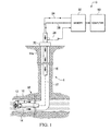
- Figure 1 illustrates an example of a logging-while-drilling (LWD) system S for gathering data about subsurface formations during drilling.
- the system S may be one of several commercially available types used during drilling operations at a wellsite to gather data. Once the data has been obtained, it is then available for processing in a manner to be set forth according to the present invention.
- the system S includes as a part of the drilling rig a downhole subassembly 10 that moves within a borehole 14 behind a drill bit 12.
- the subassembly 10 is connected at a lower end of a drill string 16 during drilling of the borehole 14.
- the downhole subassembly 10 is preferably positioned as close as practical to the drill bit 12.
- the drill bit 12 and the borehole 14 have during the progress of drilling transitioned from an initial vertical direction from an upper borehole portion 14a to a generally horizontal path into a subsurface earth formation 18 containing hydrocarbons of interest and located among other non-hydrocarbon bearing formations in the earth.
- the drill bit 12 may be rotated in several ways during drilling operations.
- the drill bit 12 may be rotated by a downhole motor which may be contained in a downhole subassembly 10.
- the drill bit 12 may also be driven by rotating the drill string 16 by a surface prime mover 20 to drill the borehole 14 in the earth formations 18.
- a surface prime mover 20 to drill the borehole 14 in the earth formations 18.
- the downhole assembly 10 contains various sensors and devices of the conventional type for gathering data and receiving signals from the wellhead during drilling operations. If desired, a conventional measuring-while-drilling or MWD system may be used in place of the LWD system 10.
- Well logging data from the downhole subassembly 10 are telemetered by a downhole telemetry system (not shown) in the downhole subassembly 10 to an uphole data processing system D.
- the uplink data telemetry path is indicated by a phantom or broken line 22 in the boreholes 14 and 14a and by communication lines indicated schematically at 24 and 26.
- Data from the downhole subassembly 10 are received and stored as functions of borehole depth by conventional uphole telemetry in a suitable data memory 30 including a data records unit and a data input unit. The data received from the downhole subassembly 10 and stored in the memory 30 are then available for processing in the data processing system D.
- the telemetry system utilized in the present invention may be of several conventional, commercially available types, including either MWD or LWD well telemetry systems. It should also be understood that there are several commercially available well telemetry systems which are capable of providing well data about formation parameters of interest derived from well drilling as the well is being drilled that may be used for gathering data. Once the data are gathered, they are available for processing according to the present invention.
- the data processing systems D of each of Figures 1 and 2 receive and process the data of interest such that the parameters of interest are recorded and displayed in the desired manner which is usually a plot of the parameters of interest as a function of depth within the borehole at which they are determined.
- the data processing systems D also typically receive input data from the data memory unit 30 which are telemetered downhole in the conventional manner by a downlink telemetry path denoted by the broken line 22 to the downhole subassembly 10.
- the LWD system 10 also includes a surface depth measurement system, such as a depth measure wheel and associated circuitry 28.
- a depth measurement system (not shown) also is typically included in the downhole subassembly 10 which enable a downhole computer to more accurately correlate or compute various sensor measurements and parameters of interest to their respective depths or true locations within the borehole 14 at which such measurements are made.
- the LWD data from the downhole subassembly 10 are subjected to conventional preprocessing and recorded as functions of borehole depth in the data memory 30. Once recorded, the LWD data measurements are available for processing and transferred as needed into the data processing system D.
- the LWD data are processed by data processing system D to obtain well logs based on the types of measurements made in the downhole subassembly 10.
- the data available from the LWD data logs are measures of the thickness of the formation 18 of interest and measures of the porosity of formation as a function of depth, a porosity log.
- the formation thickness and porosity log data obtained from the LWD data from the well bore 14 in formation 18 are then available for processing in the data processing system D according to the present invention in a manner to be set forth below.
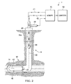
- a conventional well logging system W is shown in Figure 2 in the well 10.
- the well logging system W is a separate type of logging system that the LWD logging system S of Figure 1 and is used to obtain further data measurements for additional well logs from the well bore 14 in formation 18 which are in turn processed in accordance with the present invention.
- a sonde or logging tool housing 40 containing one or more conventional types of well logging instruments 42 is connected at a lower end of a conductive wireline cable 43 which is routed or ported through drill tubing or pipe 44 to which the sonde 40 is attached.
- the wireline cable 43 permits transfer of signals and data in each direction between the well logging instruments 42 and surface electronics, as indicated schematically at 41 and 45.
- the sonde 40 is advanced at the lower end of the tubing 44 into the well bore 14 to obtain the responses to the well logging instruments 42 of subsurface formations including the formation 18 of interest.
- the following types of well logging measurements be obtained by instruments 42 from the subsurface formation: an NMR or nuclear magnetic resonance log; a permeability or electrofacies log; a resistivity log, e.g. induction log, laterolog; a gamma ray log; and a porosity log, e.g. density log, neutron log, sonic log.
- the sonde 40 need not contain all of these logging instruments, and may contain one or more of such instruments. In the latter case, sufficient logging passes are made with different well logging tools to obtain well logging measurements of all desired types for formation depths of interest.
- the sonde 40 and tubing 44 are supported and advanced in the well by a tubing injector 46.
- a depth measuring sensor 48 forms a measure of the length of tubing 44 inserted into the well.
- the well logging measurements obtained by the well logging instruments in the sonde 40 are recorded as functions of borehole depth as provided by sensor 48 in a suitable data memory unit such as a unit 30 like that of Figure 1 . Once recorded, the well logging data measurements are then available for processing and transferred as needed into the data processing system D.
- the logging data from logging instruments 42 in the sonde 40 are processed by data processing system D to obtain well logs based on the types of measurements made by the logging instruments.
- the logging instruments are: measures of the viscosity of the fluid as a function of depth in the well and the formation 18 of interest, a viscosity log; and measures of the permeability of formation as a function of depth in the well and the formation 18 of interest, a permeability log.
- the viscosity log is typically obtained from data obtained by an NMR log
- the permeability log is typically obtained from data obtained by an electrofacies log.
- the viscosity log and permeability log data obtained from the well log data from the well bore 14 in formation 18 are then available for processing in the data processing system D according to the present invention in a manner to be set forth below. Measures of formation water saturation can be determined based on data obtained from a resistivity log.
- the processed LWD and well log data measurement obtained may, if desired, be transmitted by satellite or other suitable telemetry link for processing according to the present invention by a computer located at an office or other facility which is considerably distant from the area of the well being drilled or logged.
- the data processing system D at the well site, or the computer at a remote office accesses the logging data measurements obtained in the system S ( Figure 1 ) and the system W ( Figure 2 ) to undertake the logic of the present invention and obtain a measure of transmissibility of fluid in subsurface formations, which may be executed by a processor as a series of computer-executable instructions.
- the data processing system D of each of Figures 1 and 2 includes a computer 50 having a processor 52 and memory 54 coupled to the processor 52 to store operating instructions, control information and database records therein.
- the computer 50 may, if desired, be a multicore processor with nodes such as those from Intel Corporation or Advanced Micro Devices (AMD), or a mainframe computer of any conventional type of suitable processing capacity such as those available from International Business Machines (IBM) of Armonk, N.Y. or other source.
- IBM International Business Machines
- digital processors may be used, such as personal computers in the form of a laptop computer, notebook computer or other suitable programmed or programmable digital data processing apparatus.
- the computer 50 has a user interface 56 and an output display 58 for displaying output data or records of processing of well logging data measurements performed according to the present invention to obtain a measure of transmissibility of fluid in subsurface formations.
- the output display 58 includes components such as a printer and an output display screen capable of providing printed output information or visible displays in the form of graphs, data sheets, graphical images, data plots and the like as output records or images.
- the user interface 56 of computer 50 also includes a suitable user input device or input/output control unit 60 to provide a user access to control or access information and database records and operate the computer 50.
- Data processing system D further includes a database 62 stored in memory, which may be internal memory 54, or an external, networked, or non-networked memory as indicated at 64 in an associated database server 66.
- the data processing system D includes program code 68 stored in memory 54 of the computer 50.
- the program code 68 is in the form of computer operable instructions causing the data processor 52 to form obtain a measure of transmissibility of fluid in subsurface formations, as will be set forth.
- program code 68 may be in the form of microcode, programs, routines, or symbolic computer operable languages that provide a specific set of ordered operations that control the functioning of the data processing system D and direct its operation.
- the instructions of program code 68 may be may be stored in memory 54 of the computer 50, or on computer diskette, magnetic tape, conventional hard disk drive, electronic read-only memory, optical storage device, or other appropriate data storage device having a computer usable medium stored thereon.
- Program code 68 may also be contained on a data storage device such as server 64 as a computer readable medium, as shown.
- a flow chart F of Figure 4 herein illustrates the structure of the logic of the present invention as embodied in computer program software.
- the flow charts illustrate the structures of computer program code elements that function according to the present invention.
- the invention is practiced in its essential embodiment by computer components that use the program code instructions in a form that instructs the digital data processing system D to perform a sequence of processing steps corresponding to those shown in the flow chart F.
- the flow chart F is a high-level logic flowchart illustrates a method according to the present invention of forming a measure of transmissibility of fluid in subsurface formations.
- the method of the present invention performed in the computer 50 can be implemented utilizing the computer program steps of Figure 4 stored in memory 54 and executable by system processor 52 of computer 50.
- the logging data resulting from measurements taken with he logging system S of Figure 1 and the logging system W of Figure 2 are provided as inputs to the data processing system D, as well as laboratory data including data regarding relative permeability of formation rock samples to oil and to water.
- step 100 data from well logs obtained as disclosed above are assembled for further processing. Additionally, if desired, laboratory data regarding the relative permeability to oil of the formation rock and the relative permeability to water of the formation rock are provided, as will be described. As shown at step 102, a measure of the thickness h of the formation based on measurements from the LWD well logging tool 10 at the depth of interest is obtained.
- a measure of the permeability k of the formation is obtained at the same depth of interest based on logging measurements from a well logging tool, such as from an electrofacies log obtained by instrumentation in the logging sonde 40.
- a logging technique is known in the art as a Facimage.
- a measure of the viscosity ⁇ of the formation fluid is obtained at the same depth of interest, based on logging measurements from a well logging tool such as such as from an NMR log obtained by instrumentation in the logging sonde 20. Then during step 108, based on the obtained measures of the thickness h , permeability k, and viscosity ⁇ , the transmissibility T of fluid at the particular depth of interest in the subsurface formation is determined. With the present invention, it has been found that the transmissibility measurements obtained are in effect model or pseudo flow profiles comparable in information content and accuracy to those which are available from a production logging tool or PLT.
- a model flow profile is obtained by determining the transmissibility at each point or depth in the well bore where the tool is sampling.
- Thickness is obtained by knowing the sampling frequency of data measurement by the logging tool.
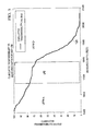
- Permeability is provided by the conventional Facimage technique. This technique is based on a mathematical and probabilistic process and model which in turn depend on wellbore logs and offset well logs to provide an accurate approximation of permeability. Viscosity is calculated as a byproduct of time relaxation measurements taken by the NMR logging tool. The parameters are processed in the data processing system D according to Equation above (2) to determine transmissibility at the corresponding depth where the log data were obtained. From bottom to top of the zone of interest in the well bore, transmissibility is cumulatively summed up and plotted as a function of depth to produce a flow profile prediction or pseudo flow profile for the zones of interest, such as that shown at 120 in Figure 5 .
- the pseudo flow profile 120 is not matching the actual flow profile 122.
- the main reason behind this difference has been determined according to the present invention to be because the relative permeability is not taken into account when processing according to Equation (2).
- Equation (2) is modified and processing of data occurs such that relative permeability is included in the determination.
- relative permeability is determined using porosity, permeability and, water saturation.
- porosity and permeability a term called flow zone indicator is determined and then used to determine the hydraulic unit which determines the proper relative permeability curve.
- water saturation calculated in the logs, a value for relative permeability to oil and water can be obtained and utilized in Equations (4) and (6).
- the determined transmissibility values of oil and water at depth points of interest are determined and the oil and water transmissibilty measures are then added to form a total transmissibility at the corresponding depth point during a step 110.
- the depth of interest is incremented to the next depth of interest as indicated at step 112, and processing returns as indicated to step 102.
- the cumulative transmissibility is plotted by display 60 as a function of depth. Plotting results in a display of a measure such as that shown in green at 124 in Figure 7 along with the actual flow profile 122 of Figure 6 and the pseudo flow profile 120 of Figures 5 and 6 .
- the green curve 124 fits the actual plot 122 from a PLT log, which is directly a result of taking into account the relative permeability factor in the determination of the transmissibility.
- Figure 7 demonstrates the importance of adding dynamic factors such as relative permeability to have more accurate results.
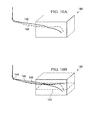
- Figure 8A is a comparison plot of data from an actual well showing cumulative transmissibility as a function of measured depth of a flow profile 126 from a conventional PLT log and a flow profile 128 which was obtained without taking relative permeability into account.
- Figure 8B is a comparison plot of data from the same actual well showing the same cumulative transmissibility as a function of measured depth of a flow profile 126 of Figure 8A from a conventional PLT log and a flow profile 130 which was obtained having taken relative permeability into account according relative permeability in determining transmissibility. Again, the flow profile 130 can be seen to better track the flow profile 126 than the results for flow profile 128 of Figure 8A .
- Figure 9 is another example from an actual well to illustrate the advantages of the present invention.
- Figure 9 shows a comparison plot of data obtained and plotted from a production logging tool in an actual well as indicated at 130 in Figure 9 and a plot 132 of a pseudo flow profile formed according to the present invention.
- the plots 130 and 132 are superimposed over customary plots of other well log data from conventional PLT and other well logs regarding the subsurface zone of interest.
- an excellent match exists between the PLT log data 130 and the flow profile 132 according to the present invention.
- Utilizing the techniques of the present invention provides economic benefits due to the fact that time and resources are saved as opposed to having to run of expensive production logging tools or PLT's for every newly drilled well.
- a pseudo flow profile for a planned wells is formed utilizing data obtained from a geological model shown at 140 in Figures 10A and 10B of a reservoir of interest.
- the model may be, for example, formed in a reservoir simulator of the type described in commonly owned U. S. Patent No. 7,809,537 , or of the type known as the POWERS simulator described in the literature.
- a transmissibility model for oil and water is formed using Equations (4) and (6) for each cell in the model 140 in the zone of interest. Data indicative of the placement and path of the projected well is then inserted in the model, and data values retrieved for viscosity, thickness, and relative permeability to oil and water at the cell locations in the model where the trajectory of the well intersects the cells of interest. An example depth for such an intersection in the model 140 is shown at 142 in Figure 10B .
- the transmissibility for both oil and water are determined and summed.
- the results are then plotted as a function of depth forming a display like that shown at 124 in Figure 7 to obtain a predicted or simulated pseudo flow profile.
- the resultant flow profile is then evaluated.
- Alternative well placements for improved flow may be evaluated by changing well placement either vertically, horizontally or azimuthally.
- the process of the present invention thus helps in better well planning, optimized well production, and minimization of the use of expensive logging tools such as NMR (Nuclear Magnetic Resonance tool).
- NMR Nuclear Magnetic Resonance tool
- they can be evaluated and their position adjusted to have uniform water fronts in a peripheral water injection scheme.
- Figures 10A and 10B show schematically some possible well placements that could occur in a reservoir, using the flow prediction method according to the present invention for the model. The results can indicate which well placement or trajectory would optimize well production and thus assist in planning the drilling program accordingly.
- the present invention uses field and log data, along with lab results and measurements to generate and predict Injection/Production profiles for wells of interest.
- the present invention thus enables reservoir engineers to measure, evaluate and compare an accurate model of transmissibility prediction to actual PLT data. This is valuable in assessment of a well's expected profile and the effectiveness of well stimulation techniques.
- the present invention accumulates data acquired from the logging instrumentation in the various logging tools foot for foot of measured depth in the well.
- the logging data is also if desired combined with laboratory data to produce a transmissibility curve that indicates the flow profile of a well of interest with accuracy.
- the present invention also enables a reservoir engineer to make confident decisions about which wells require a PLT log and which wells need not based on actual compiled data as opposed to making estimates or guesses by looking at each data component and parameter separately.
- the present invention enables a reservoir engineer or analyst to compare predicted flow profiles obtained as described above with PLT data, when available, and to investigate discrepancies which might exist. Examples include those caused due to fractures, thief zones, a bad stimulation job, and the like.
- the present invention also provides more confidence in deciding whether or not to run a PLT log in a particular well.
- the present invention also provides more confidence about flow profile data from a well in situations when a decision is made not to run a PLT in the well.
- the present invention also saves time by avoiding delays which occur while waiting for a PLT log to be run in a well, and provides cost savings by eliminating PLT logs in cases where reservoir engineers are if comfortable with the predicted flow profiles obtained with the present invention.
Landscapes
- Engineering & Computer Science (AREA)
- Life Sciences & Earth Sciences (AREA)
- Physics & Mathematics (AREA)
- Geology (AREA)
- Mining & Mineral Resources (AREA)
- General Life Sciences & Earth Sciences (AREA)
- Geophysics (AREA)
- Environmental & Geological Engineering (AREA)
- Geochemistry & Mineralogy (AREA)
- Fluid Mechanics (AREA)
- Remote Sensing (AREA)
- General Physics & Mathematics (AREA)
- Geophysics And Detection Of Objects (AREA)
- Investigation Of Foundation Soil And Reinforcement Of Foundation Soil By Compacting Or Drainage (AREA)
- Physical Or Chemical Processes And Apparatus (AREA)
Applications Claiming Priority (2)
| Application Number | Priority Date | Filing Date | Title |
|---|---|---|---|
| US12/987,526 US20120179379A1 (en) | 2011-01-10 | 2011-01-10 | Flow Profile Modeling for Wells |
| EP12703185.4A EP2663737B1 (de) | 2011-01-10 | 2012-01-05 | Flussprofilmodellierung für bohrlöcher |
Related Parent Applications (2)
| Application Number | Title | Priority Date | Filing Date |
|---|---|---|---|
| EP12703185.4A Division-Into EP2663737B1 (de) | 2011-01-10 | 2012-01-05 | Flussprofilmodellierung für bohrlöcher |
| EP12703185.4A Division EP2663737B1 (de) | 2011-01-10 | 2012-01-05 | Flussprofilmodellierung für bohrlöcher |
Publications (2)
| Publication Number | Publication Date |
|---|---|
| EP3012402A1 true EP3012402A1 (de) | 2016-04-27 |
| EP3012402B1 EP3012402B1 (de) | 2018-04-11 |
Family
ID=45569738
Family Applications (4)
| Application Number | Title | Priority Date | Filing Date |
|---|---|---|---|
| EP15196093.7A Not-in-force EP3020915B1 (de) | 2011-01-10 | 2012-01-05 | Flussprofilmodellierung für bohrlöcher |
| EP15196092.9A Not-in-force EP3012402B1 (de) | 2011-01-10 | 2012-01-05 | Flussprofilmodellierung für bohrlöcher |
| EP15196091.1A Not-in-force EP3012401B1 (de) | 2011-01-10 | 2012-01-05 | Flussprofilmodellierung für bohrlöcher |
| EP12703185.4A Not-in-force EP2663737B1 (de) | 2011-01-10 | 2012-01-05 | Flussprofilmodellierung für bohrlöcher |
Family Applications Before (1)
| Application Number | Title | Priority Date | Filing Date |
|---|---|---|---|
| EP15196093.7A Not-in-force EP3020915B1 (de) | 2011-01-10 | 2012-01-05 | Flussprofilmodellierung für bohrlöcher |
Family Applications After (2)
| Application Number | Title | Priority Date | Filing Date |
|---|---|---|---|
| EP15196091.1A Not-in-force EP3012401B1 (de) | 2011-01-10 | 2012-01-05 | Flussprofilmodellierung für bohrlöcher |
| EP12703185.4A Not-in-force EP2663737B1 (de) | 2011-01-10 | 2012-01-05 | Flussprofilmodellierung für bohrlöcher |
Country Status (4)
| Country | Link |
|---|---|
| US (4) | US20120179379A1 (de) |
| EP (4) | EP3020915B1 (de) |
| CA (1) | CA2821181C (de) |
| WO (1) | WO2012096826A2 (de) |
Families Citing this family (23)
| Publication number | Priority date | Publication date | Assignee | Title |
|---|---|---|---|---|
| US20120179379A1 (en) * | 2011-01-10 | 2012-07-12 | Saudi Arabian Oil Company | Flow Profile Modeling for Wells |
| US8965703B2 (en) * | 2011-10-03 | 2015-02-24 | Schlumberger Technology Corporation | Applications based on fluid properties measured downhole |
| US20130282286A1 (en) * | 2012-04-20 | 2013-10-24 | Chevron U.S.A. Inc. | System and method for calibrating permeability for use in reservoir modeling |
| AU2012388240B2 (en) * | 2012-08-20 | 2016-05-19 | Landmark Graphics Corporation | Methods and systems of incorporating pseudo-surface pick locations in seismic velocity models |
| WO2014158333A1 (en) * | 2013-03-13 | 2014-10-02 | Exxonmobil Upstream Research Company | Producing hydrocarbons from a formation |
| CA2940191C (en) | 2014-02-26 | 2018-03-06 | BHL Boresight, Inc. | Geosteering systems and methods thereof |
| US9784885B2 (en) | 2014-06-27 | 2017-10-10 | Saudi Arabian Oil Company | Methods and systems for estimating sizes and effects of wellbore obstructions in water injection wells |
| CN104297131B (zh) * | 2014-11-04 | 2016-09-21 | 中国石油大学(华东) | 一种砾质砂岩储层孔隙度校正方法 |
| US10007015B2 (en) | 2015-02-23 | 2018-06-26 | Nexen Energy Ulc | Methods, systems and devices for predicting reservoir properties |
| WO2016134443A1 (en) * | 2015-02-23 | 2016-09-01 | Nexen Energy Ulc | Methods, systems and devices for predicting reservoir properties |
| US10846445B2 (en) | 2015-06-18 | 2020-11-24 | M-I L.L.C. | Method of waste distribution and formation pressure profile determination |
| WO2016205774A1 (en) * | 2015-06-18 | 2016-12-22 | M-I L.L.C. | Method of waste distribution and formation pressure profile determination |
| US10762254B2 (en) | 2015-11-04 | 2020-09-01 | Halliburton Energy Services, Inc. | Simulating multi-dimensional flow with coupled one-dimensional flow paths |
| CN106323836B (zh) * | 2016-08-11 | 2019-01-18 | 中国石油天然气股份有限公司 | 一种井壁渗透率计算方法及装置 |
| CN110462163B (zh) * | 2017-05-08 | 2023-04-18 | 哈利伯顿能源服务公司 | 用于使用地层数据的像素化解来评估地层的系统和方法 |
| CN106991509A (zh) * | 2017-05-27 | 2017-07-28 | 重庆科技学院 | 基于径向基函数神经网络模型的测井曲线预测方法 |
| AU2020277968A1 (en) | 2019-05-21 | 2021-12-16 | Geoquest Systems B.V. | Drilling control |
| CN110608032B (zh) * | 2019-09-18 | 2023-01-24 | 中国石油天然气集团有限公司 | 一种基于轻烃录井的油井产量预测方法及计算机设备 |
| CN110671082B (zh) * | 2019-09-19 | 2022-03-01 | 大庆油田有限责任公司 | 一种砂岩油藏薄差油层注水井注入大剂量驱油液后井组的调整方法 |
| CN110939412B (zh) * | 2019-12-13 | 2021-07-20 | 延长油田股份有限公司富县采油厂 | 一种利用水平井实现超前注水与早期注水的开发方法 |
| US11727583B2 (en) * | 2020-09-02 | 2023-08-15 | Baker Hughes Oilfield Operations Llc | Core-level high resolution petrophysical characterization method |
| CN112576238B (zh) * | 2020-12-02 | 2022-10-28 | 中国石油大学(华东) | 一种低渗透油藏剩余油位置与含量测定系统、方法及应用 |
| US12503938B2 (en) | 2024-03-04 | 2025-12-23 | Rna Capital, Inc. | Drilling optimization method |
Citations (3)
| Publication number | Priority date | Publication date | Assignee | Title |
|---|---|---|---|---|
| EP1158312A1 (de) * | 2000-05-26 | 2001-11-28 | Institut Francais Du Petrole | Methode zur Modellierung von Strömungen in einem mit grossen Brüchen versehenen Bruchsystem |
| WO2009048781A1 (en) * | 2007-10-12 | 2009-04-16 | Exxonmobil Upstream Research Company | Non-destructive determination of the pore size distribution and the distribution of fluid flow velocities |
| US7809537B2 (en) | 2004-10-15 | 2010-10-05 | Saudi Arabian Oil Company | Generalized well management in parallel reservoir simulation |
Family Cites Families (36)
| Publication number | Priority date | Publication date | Assignee | Title |
|---|---|---|---|---|
| US3771360A (en) * | 1971-09-27 | 1973-11-13 | Shell Oil Co | Vertical permeability test |
| US4348897A (en) * | 1979-07-18 | 1982-09-14 | Krauss Kalweit Irene | Method and device for determining the transmissibility of a fluid-conducting borehole layer |
| US4692908A (en) * | 1982-03-24 | 1987-09-08 | Schlumberger-Doll Research | Method and apparatus for investigating stand-off in a borehole |
| US4622643A (en) * | 1983-10-21 | 1986-11-11 | Mobil Oil Corporation | Method for determining consistent water relative permeability values from dynamic displacement data |
| US5502686A (en) * | 1994-08-01 | 1996-03-26 | Western Atlas International | Method and apparatus for imaging a borehole sidewall |
| US5812068A (en) * | 1994-12-12 | 1998-09-22 | Baker Hughes Incorporated | Drilling system with downhole apparatus for determining parameters of interest and for adjusting drilling direction in response thereto |
| US6498989B1 (en) * | 1997-08-11 | 2002-12-24 | Trans Seismic International, Inc. | Method for predicting dynamic parameters of fluids in a subterranean reservoir |
| US6023164A (en) * | 1998-02-20 | 2000-02-08 | Numar Corporation | Eccentric NMR well logging apparatus and method |
| US6140817A (en) * | 1998-05-26 | 2000-10-31 | Schlumberger Technology Corporation | Magnetic resonance well logging method and apparatus |
| US8682589B2 (en) * | 1998-12-21 | 2014-03-25 | Baker Hughes Incorporated | Apparatus and method for managing supply of additive at wellsites |
| US6295504B1 (en) * | 1999-10-25 | 2001-09-25 | Halliburton Energy Services, Inc. | Multi-resolution graph-based clustering |
| US6477469B2 (en) * | 2001-01-08 | 2002-11-05 | Halliburton Energy Services, Inc. | Coarse-to-fine self-organizing map for automatic electrofacies ordering |
| US7032661B2 (en) | 2001-07-20 | 2006-04-25 | Baker Hughes Incorporated | Method and apparatus for combined NMR and formation testing for assessing relative permeability with formation testing and nuclear magnetic resonance testing |
| US7059179B2 (en) * | 2001-09-28 | 2006-06-13 | Halliburton Energy Services, Inc. | Multi-probe pressure transient analysis for determination of horizontal permeability, anisotropy and skin in an earth formation |
| US6732799B2 (en) | 2001-10-24 | 2004-05-11 | Bradley J. Challacombe | Apparatus for stimulating oil extraction by increasing oil well permeability using specialized explosive detonating cord |
| NO328485B1 (no) * | 2002-04-02 | 2010-03-01 | Baker Hughes Inc | Anordning og fremgangsmate for anslag av relativ permeabilitet i en formasjon ved hjelp av NMR, resistivitet og formasjonsproving |
| NL1024444C2 (nl) * | 2003-10-03 | 2005-04-08 | J O A Beheer B V | Werkwijze, inrichting, computerprogramma en gegevensdrager voor het met een digitale verwerkingseenheid modelleren van een meerdimensionale heterogene structuur. |
| US7031841B2 (en) * | 2004-01-30 | 2006-04-18 | Schlumberger Technology Corporation | Method for determining pressure of earth formations |
| US7980312B1 (en) * | 2005-06-20 | 2011-07-19 | Hill Gilman A | Integrated in situ retorting and refining of oil shale |
| US8620636B2 (en) * | 2005-08-25 | 2013-12-31 | Schlumberger Technology Corporation | Interpreting well test measurements |
| US7538547B2 (en) * | 2006-12-26 | 2009-05-26 | Schlumberger Technology Corporation | Method and apparatus for integrating NMR data and conventional log data |
| US7805982B2 (en) | 2007-03-06 | 2010-10-05 | Saudi Arabian Oil Company | Portable core flood apparatus for conducting on-site permeability measurements |
| US7853045B2 (en) | 2007-10-31 | 2010-12-14 | Saudi Arabian Oil Company | Geostatistical analysis and classification of core data |
| US8121788B2 (en) | 2007-12-21 | 2012-02-21 | Schlumberger Technology Corporation | Method and system to automatically correct LWD depth measurements |
| US7849736B2 (en) * | 2007-12-21 | 2010-12-14 | Schlumberger Technology Corporation | Method for calculating the ratio of relative permeabilities of formation fluids and wettability of a formation downhole, and a formation testing tool to implement the same |
| WO2009108394A2 (en) * | 2008-02-29 | 2009-09-03 | Saudi Arabian Oil Company | Monitoring of reservoir fluid moving along flow pathways in a producing oil field using passive seismic emissions |
| US8061444B2 (en) * | 2008-05-22 | 2011-11-22 | Schlumberger Technology Corporation | Methods and apparatus to form a well |
| US8120357B2 (en) * | 2008-05-30 | 2012-02-21 | Schlumberger Technology Corporation | Method and system for fluid characterization of a reservoir |
| US8060311B2 (en) * | 2008-06-23 | 2011-11-15 | Schlumberger Technology Corporation | Job monitoring methods and apparatus for logging-while-drilling equipment |
| US7893692B2 (en) * | 2008-11-03 | 2011-02-22 | Schlumberger Technology Corporation | Method for estimating the formation productivity from nuclear magnetic resonance measurements |
| US8258790B2 (en) * | 2008-11-20 | 2012-09-04 | Baker Hughes Incorporated | Oscillator sensor for determining a property of an earth formation |
| EP2359306B1 (de) * | 2008-11-21 | 2017-08-02 | Exxonmobil Upstream Research Company | Verfahren und systeme für modellierung, entwurf und ausführung von bohroperationen mit vibrationsberücksichtigung |
| US8473214B2 (en) * | 2009-04-24 | 2013-06-25 | Schlumberger Technology Corporation | Thickness-independent computation of horizontal and vertical permeability |
| US8175751B2 (en) * | 2009-05-27 | 2012-05-08 | Chevron U.S.A. Inc. | Computer-implemented systems and methods for screening and predicting the performance of enhanced oil recovery and improved oil recovery methods |
| US8725478B2 (en) * | 2010-08-09 | 2014-05-13 | Conocophillips Company | Reservoir upscaling method with preserved transmissibility |
| US20120179379A1 (en) * | 2011-01-10 | 2012-07-12 | Saudi Arabian Oil Company | Flow Profile Modeling for Wells |
-
2011
- 2011-01-10 US US12/987,526 patent/US20120179379A1/en not_active Abandoned
-
2012
- 2012-01-05 CA CA2821181A patent/CA2821181C/en active Active
- 2012-01-05 EP EP15196093.7A patent/EP3020915B1/de not_active Not-in-force
- 2012-01-05 EP EP15196092.9A patent/EP3012402B1/de not_active Not-in-force
- 2012-01-05 EP EP15196091.1A patent/EP3012401B1/de not_active Not-in-force
- 2012-01-05 WO PCT/US2012/020323 patent/WO2012096826A2/en not_active Ceased
- 2012-01-05 EP EP12703185.4A patent/EP2663737B1/de not_active Not-in-force
-
2013
- 2013-09-23 US US14/034,040 patent/US10662763B2/en active Active
- 2013-09-24 US US14/034,777 patent/US20140025302A1/en not_active Abandoned
- 2013-09-24 US US14/034,749 patent/US20140025360A1/en not_active Abandoned
Patent Citations (3)
| Publication number | Priority date | Publication date | Assignee | Title |
|---|---|---|---|---|
| EP1158312A1 (de) * | 2000-05-26 | 2001-11-28 | Institut Francais Du Petrole | Methode zur Modellierung von Strömungen in einem mit grossen Brüchen versehenen Bruchsystem |
| US7809537B2 (en) | 2004-10-15 | 2010-10-05 | Saudi Arabian Oil Company | Generalized well management in parallel reservoir simulation |
| WO2009048781A1 (en) * | 2007-10-12 | 2009-04-16 | Exxonmobil Upstream Research Company | Non-destructive determination of the pore size distribution and the distribution of fluid flow velocities |
Non-Patent Citations (3)
| Title |
|---|
| C. S. KABIR ET AL: "Obtaining Reservoir Parameters abd Flow Profiles From Production-Logging Runs", 11 October 1996 (1996-10-11), Abu Dhabi U. A. E., XP055254033, Retrieved from the Internet <URL:https://www.onepetro.org/download/conference-paper/SPE-49537-MS?id=conference-paper/SPE-49537-MS> [retrieved on 20160301] * |
| DOGRU, A.H. ET AL.: "A Massively Parallel Reservoir Simulator for Large Scale Reservoir Simulation", PAPER SPE 51886 PRESENTED AT THE 1999 SPE RESERVOIR SIMULATION SYMPOSIUM, February 1999 (1999-02-01) |
| DOGRU, A.H.; DREIMAN, W.T.; HEMANTHKUMAR, K.; FUNG, L.S.: "Simulation of Super K Behavior in Ghawar by a Multi-Million Cell Parallel Simulator", PAPER SPE 68066 PRESENTED AT THE MIDDLE EAST OIL SHOW, March 2001 (2001-03-01) |
Also Published As
| Publication number | Publication date |
|---|---|
| CA2821181A1 (en) | 2012-07-19 |
| EP2663737B1 (de) | 2016-03-16 |
| EP2663737A2 (de) | 2013-11-20 |
| US10662763B2 (en) | 2020-05-26 |
| US20140025302A1 (en) | 2014-01-23 |
| EP3012402B1 (de) | 2018-04-11 |
| EP3012401A1 (de) | 2016-04-27 |
| US20140025360A1 (en) | 2014-01-23 |
| WO2012096826A3 (en) | 2013-08-22 |
| US20140025303A1 (en) | 2014-01-23 |
| CA2821181C (en) | 2019-12-03 |
| EP3020915B1 (de) | 2017-03-01 |
| EP3012401B1 (de) | 2018-03-28 |
| EP3020915A1 (de) | 2016-05-18 |
| US20120179379A1 (en) | 2012-07-12 |
| WO2012096826A2 (en) | 2012-07-19 |
Similar Documents
| Publication | Publication Date | Title |
|---|---|---|
| EP3020915B1 (de) | Flussprofilmodellierung für bohrlöcher | |
| CN108713089B (zh) | 基于钻孔流体和钻探录井估计地层性质 | |
| CA2725923C (en) | Heterogeneous earth models for a reservoir field | |
| US7924001B2 (en) | Determination of oil viscosity and continuous gas oil ratio from nuclear magnetic resonance logs | |
| MX2008015872A (es) | Metodo y sistema para diseñar y optimizar operaciones de perforacion y de terminacion en yacimientos de hidrocarburos. | |
| CN104011564B (zh) | 4d饱和度建模 | |
| MX2015002141A (es) | Sistema y metodo para realizar operaciones de estimulacion. | |
| US10145985B2 (en) | Static earth model calibration methods and systems using permeability testing | |
| EP3526627B1 (de) | Petrophysikalische feldauswertung mit selbstorganisierter karte | |
| US9575195B2 (en) | Detecting and quantifying hydrocarbon volumes in sub-seismic sands in the presence of anisotropy | |
| US12410698B2 (en) | Fracture characterization while drilling | |
| US20180156937A1 (en) | Methods and approaches for geomechanical stratigraphic systems | |
| US20230280494A1 (en) | Proper layout of data in gpus for accelerating line solve pre-conditioner used in iterative linear solvers in reservoir simulation | |
| US20210232868A1 (en) | Categorizng fractures in a subsurface formation | |
| Beardsmore et al. | Geothermal systems assessment—Identification and mitigation of EGS exploration risk | |
| US20250270923A1 (en) | Methods and systems for validation of permeability models based on cumulative flow | |
| Sarmah et al. | Evaluating the Effect of Input Model Uncertainties on Hydraulic Fracture Modeling and Pressure History Matching | |
| Childers | Introducing the connected reservoir storage concept for reservoir characterization and production forecast | |
| Bøklepp | Decision Framework for Petrophysical Data Acquisition in the Development Well Planning Process | |
| Alvarez et al. | Unconventional Resources Technology Conference, 20–22 June 2022 |
Legal Events
| Date | Code | Title | Description |
|---|---|---|---|
| PUAI | Public reference made under article 153(3) epc to a published international application that has entered the european phase |
Free format text: ORIGINAL CODE: 0009012 |
|
| AC | Divisional application: reference to earlier application |
Ref document number: 2663737 Country of ref document: EP Kind code of ref document: P |
|
| AK | Designated contracting states |
Kind code of ref document: A1 Designated state(s): AL AT BE BG CH CY CZ DE DK EE ES FI FR GB GR HR HU IE IS IT LI LT LU LV MC MK MT NL NO PL PT RO RS SE SI SK SM TR |
|
| STAA | Information on the status of an ep patent application or granted ep patent |
Free format text: STATUS: REQUEST FOR EXAMINATION WAS MADE |
|
| 17P | Request for examination filed |
Effective date: 20161027 |
|
| RBV | Designated contracting states (corrected) |
Designated state(s): AL AT BE BG CH CY CZ DE DK EE ES FI FR GB GR HR HU IE IS IT LI LT LU LV MC MK MT NL NO PL PT RO RS SE SI SK SM TR |
|
| GRAP | Despatch of communication of intention to grant a patent |
Free format text: ORIGINAL CODE: EPIDOSNIGR1 |
|
| STAA | Information on the status of an ep patent application or granted ep patent |
Free format text: STATUS: GRANT OF PATENT IS INTENDED |
|
| INTG | Intention to grant announced |
Effective date: 20171031 |
|
| GRAS | Grant fee paid |
Free format text: ORIGINAL CODE: EPIDOSNIGR3 |
|
| GRAA | (expected) grant |
Free format text: ORIGINAL CODE: 0009210 |
|
| STAA | Information on the status of an ep patent application or granted ep patent |
Free format text: STATUS: THE PATENT HAS BEEN GRANTED |
|
| AC | Divisional application: reference to earlier application |
Ref document number: 2663737 Country of ref document: EP Kind code of ref document: P |
|
| AK | Designated contracting states |
Kind code of ref document: B1 Designated state(s): AL AT BE BG CH CY CZ DE DK EE ES FI FR GB GR HR HU IE IS IT LI LT LU LV MC MK MT NL NO PL PT RO RS SE SI SK SM TR |
|
| REG | Reference to a national code |
Ref country code: GB Ref legal event code: FG4D |
|
| REG | Reference to a national code |
Ref country code: CH Ref legal event code: EP |
|
| REG | Reference to a national code |
Ref country code: AT Ref legal event code: REF Ref document number: 988239 Country of ref document: AT Kind code of ref document: T Effective date: 20180415 |
|
| REG | Reference to a national code |
Ref country code: IE Ref legal event code: FG4D |
|
| REG | Reference to a national code |
Ref country code: DE Ref legal event code: R096 Ref document number: 602012045222 Country of ref document: DE |
|
| REG | Reference to a national code |
Ref country code: NL Ref legal event code: MP Effective date: 20180411 |
|
| REG | Reference to a national code |
Ref country code: LT Ref legal event code: MG4D |
|
| PG25 | Lapsed in a contracting state [announced via postgrant information from national office to epo] |
Ref country code: NL Free format text: LAPSE BECAUSE OF FAILURE TO SUBMIT A TRANSLATION OF THE DESCRIPTION OR TO PAY THE FEE WITHIN THE PRESCRIBED TIME-LIMIT Effective date: 20180411 |
|
| PG25 | Lapsed in a contracting state [announced via postgrant information from national office to epo] |
Ref country code: BG Free format text: LAPSE BECAUSE OF FAILURE TO SUBMIT A TRANSLATION OF THE DESCRIPTION OR TO PAY THE FEE WITHIN THE PRESCRIBED TIME-LIMIT Effective date: 20180711 Ref country code: FI Free format text: LAPSE BECAUSE OF FAILURE TO SUBMIT A TRANSLATION OF THE DESCRIPTION OR TO PAY THE FEE WITHIN THE PRESCRIBED TIME-LIMIT Effective date: 20180411 Ref country code: AL Free format text: LAPSE BECAUSE OF FAILURE TO SUBMIT A TRANSLATION OF THE DESCRIPTION OR TO PAY THE FEE WITHIN THE PRESCRIBED TIME-LIMIT Effective date: 20180411 Ref country code: NO Free format text: LAPSE BECAUSE OF FAILURE TO SUBMIT A TRANSLATION OF THE DESCRIPTION OR TO PAY THE FEE WITHIN THE PRESCRIBED TIME-LIMIT Effective date: 20180711 Ref country code: SE Free format text: LAPSE BECAUSE OF FAILURE TO SUBMIT A TRANSLATION OF THE DESCRIPTION OR TO PAY THE FEE WITHIN THE PRESCRIBED TIME-LIMIT Effective date: 20180411 Ref country code: PL Free format text: LAPSE BECAUSE OF FAILURE TO SUBMIT A TRANSLATION OF THE DESCRIPTION OR TO PAY THE FEE WITHIN THE PRESCRIBED TIME-LIMIT Effective date: 20180411 Ref country code: LT Free format text: LAPSE BECAUSE OF FAILURE TO SUBMIT A TRANSLATION OF THE DESCRIPTION OR TO PAY THE FEE WITHIN THE PRESCRIBED TIME-LIMIT Effective date: 20180411 Ref country code: ES Free format text: LAPSE BECAUSE OF FAILURE TO SUBMIT A TRANSLATION OF THE DESCRIPTION OR TO PAY THE FEE WITHIN THE PRESCRIBED TIME-LIMIT Effective date: 20180411 |
|
| PG25 | Lapsed in a contracting state [announced via postgrant information from national office to epo] |
Ref country code: HR Free format text: LAPSE BECAUSE OF FAILURE TO SUBMIT A TRANSLATION OF THE DESCRIPTION OR TO PAY THE FEE WITHIN THE PRESCRIBED TIME-LIMIT Effective date: 20180411 Ref country code: GR Free format text: LAPSE BECAUSE OF FAILURE TO SUBMIT A TRANSLATION OF THE DESCRIPTION OR TO PAY THE FEE WITHIN THE PRESCRIBED TIME-LIMIT Effective date: 20180712 Ref country code: LV Free format text: LAPSE BECAUSE OF FAILURE TO SUBMIT A TRANSLATION OF THE DESCRIPTION OR TO PAY THE FEE WITHIN THE PRESCRIBED TIME-LIMIT Effective date: 20180411 Ref country code: RS Free format text: LAPSE BECAUSE OF FAILURE TO SUBMIT A TRANSLATION OF THE DESCRIPTION OR TO PAY THE FEE WITHIN THE PRESCRIBED TIME-LIMIT Effective date: 20180411 |
|
| REG | Reference to a national code |
Ref country code: AT Ref legal event code: MK05 Ref document number: 988239 Country of ref document: AT Kind code of ref document: T Effective date: 20180411 |
|
| PG25 | Lapsed in a contracting state [announced via postgrant information from national office to epo] |
Ref country code: PT Free format text: LAPSE BECAUSE OF FAILURE TO SUBMIT A TRANSLATION OF THE DESCRIPTION OR TO PAY THE FEE WITHIN THE PRESCRIBED TIME-LIMIT Effective date: 20180813 |
|
| REG | Reference to a national code |
Ref country code: DE Ref legal event code: R097 Ref document number: 602012045222 Country of ref document: DE |
|
| PG25 | Lapsed in a contracting state [announced via postgrant information from national office to epo] |
Ref country code: RO Free format text: LAPSE BECAUSE OF FAILURE TO SUBMIT A TRANSLATION OF THE DESCRIPTION OR TO PAY THE FEE WITHIN THE PRESCRIBED TIME-LIMIT Effective date: 20180411 Ref country code: SK Free format text: LAPSE BECAUSE OF FAILURE TO SUBMIT A TRANSLATION OF THE DESCRIPTION OR TO PAY THE FEE WITHIN THE PRESCRIBED TIME-LIMIT Effective date: 20180411 Ref country code: CZ Free format text: LAPSE BECAUSE OF FAILURE TO SUBMIT A TRANSLATION OF THE DESCRIPTION OR TO PAY THE FEE WITHIN THE PRESCRIBED TIME-LIMIT Effective date: 20180411 Ref country code: EE Free format text: LAPSE BECAUSE OF FAILURE TO SUBMIT A TRANSLATION OF THE DESCRIPTION OR TO PAY THE FEE WITHIN THE PRESCRIBED TIME-LIMIT Effective date: 20180411 Ref country code: AT Free format text: LAPSE BECAUSE OF FAILURE TO SUBMIT A TRANSLATION OF THE DESCRIPTION OR TO PAY THE FEE WITHIN THE PRESCRIBED TIME-LIMIT Effective date: 20180411 Ref country code: DK Free format text: LAPSE BECAUSE OF FAILURE TO SUBMIT A TRANSLATION OF THE DESCRIPTION OR TO PAY THE FEE WITHIN THE PRESCRIBED TIME-LIMIT Effective date: 20180411 |
|
| PLBE | No opposition filed within time limit |
Free format text: ORIGINAL CODE: 0009261 |
|
| STAA | Information on the status of an ep patent application or granted ep patent |
Free format text: STATUS: NO OPPOSITION FILED WITHIN TIME LIMIT |
|
| PG25 | Lapsed in a contracting state [announced via postgrant information from national office to epo] |
Ref country code: IT Free format text: LAPSE BECAUSE OF FAILURE TO SUBMIT A TRANSLATION OF THE DESCRIPTION OR TO PAY THE FEE WITHIN THE PRESCRIBED TIME-LIMIT Effective date: 20180411 Ref country code: SM Free format text: LAPSE BECAUSE OF FAILURE TO SUBMIT A TRANSLATION OF THE DESCRIPTION OR TO PAY THE FEE WITHIN THE PRESCRIBED TIME-LIMIT Effective date: 20180411 |
|
| 26N | No opposition filed |
Effective date: 20190114 |
|
| PG25 | Lapsed in a contracting state [announced via postgrant information from national office to epo] |
Ref country code: SI Free format text: LAPSE BECAUSE OF FAILURE TO SUBMIT A TRANSLATION OF THE DESCRIPTION OR TO PAY THE FEE WITHIN THE PRESCRIBED TIME-LIMIT Effective date: 20180411 |
|
| REG | Reference to a national code |
Ref country code: DE Ref legal event code: R119 Ref document number: 602012045222 Country of ref document: DE |
|
| PG25 | Lapsed in a contracting state [announced via postgrant information from national office to epo] |
Ref country code: MC Free format text: LAPSE BECAUSE OF FAILURE TO SUBMIT A TRANSLATION OF THE DESCRIPTION OR TO PAY THE FEE WITHIN THE PRESCRIBED TIME-LIMIT Effective date: 20180411 |
|
| REG | Reference to a national code |
Ref country code: CH Ref legal event code: PL |
|
| PG25 | Lapsed in a contracting state [announced via postgrant information from national office to epo] |
Ref country code: LU Free format text: LAPSE BECAUSE OF NON-PAYMENT OF DUE FEES Effective date: 20190105 |
|
| REG | Reference to a national code |
Ref country code: BE Ref legal event code: MM Effective date: 20190131 |
|
| REG | Reference to a national code |
Ref country code: IE Ref legal event code: MM4A |
|
| PG25 | Lapsed in a contracting state [announced via postgrant information from national office to epo] |
Ref country code: DE Free format text: LAPSE BECAUSE OF NON-PAYMENT OF DUE FEES Effective date: 20190801 Ref country code: FR Free format text: LAPSE BECAUSE OF NON-PAYMENT OF DUE FEES Effective date: 20190131 |
|
| PG25 | Lapsed in a contracting state [announced via postgrant information from national office to epo] |
Ref country code: BE Free format text: LAPSE BECAUSE OF NON-PAYMENT OF DUE FEES Effective date: 20190131 |
|
| PG25 | Lapsed in a contracting state [announced via postgrant information from national office to epo] |
Ref country code: LI Free format text: LAPSE BECAUSE OF NON-PAYMENT OF DUE FEES Effective date: 20190131 Ref country code: CH Free format text: LAPSE BECAUSE OF NON-PAYMENT OF DUE FEES Effective date: 20190131 |
|
| PG25 | Lapsed in a contracting state [announced via postgrant information from national office to epo] |
Ref country code: IE Free format text: LAPSE BECAUSE OF NON-PAYMENT OF DUE FEES Effective date: 20190105 |
|
| PG25 | Lapsed in a contracting state [announced via postgrant information from national office to epo] |
Ref country code: TR Free format text: LAPSE BECAUSE OF FAILURE TO SUBMIT A TRANSLATION OF THE DESCRIPTION OR TO PAY THE FEE WITHIN THE PRESCRIBED TIME-LIMIT Effective date: 20180411 |
|
| PG25 | Lapsed in a contracting state [announced via postgrant information from national office to epo] |
Ref country code: MT Free format text: LAPSE BECAUSE OF NON-PAYMENT OF DUE FEES Effective date: 20190105 |
|
| PGFP | Annual fee paid to national office [announced via postgrant information from national office to epo] |
Ref country code: GB Payment date: 20201223 Year of fee payment: 10 |
|
| PG25 | Lapsed in a contracting state [announced via postgrant information from national office to epo] |
Ref country code: CY Free format text: LAPSE BECAUSE OF FAILURE TO SUBMIT A TRANSLATION OF THE DESCRIPTION OR TO PAY THE FEE WITHIN THE PRESCRIBED TIME-LIMIT Effective date: 20180411 |
|
| PG25 | Lapsed in a contracting state [announced via postgrant information from national office to epo] |
Ref country code: IS Free format text: LAPSE BECAUSE OF FAILURE TO SUBMIT A TRANSLATION OF THE DESCRIPTION OR TO PAY THE FEE WITHIN THE PRESCRIBED TIME-LIMIT Effective date: 20180811 |
|
| PG25 | Lapsed in a contracting state [announced via postgrant information from national office to epo] |
Ref country code: HU Free format text: LAPSE BECAUSE OF FAILURE TO SUBMIT A TRANSLATION OF THE DESCRIPTION OR TO PAY THE FEE WITHIN THE PRESCRIBED TIME-LIMIT; INVALID AB INITIO Effective date: 20120105 |
|
| PG25 | Lapsed in a contracting state [announced via postgrant information from national office to epo] |
Ref country code: MK Free format text: LAPSE BECAUSE OF FAILURE TO SUBMIT A TRANSLATION OF THE DESCRIPTION OR TO PAY THE FEE WITHIN THE PRESCRIBED TIME-LIMIT Effective date: 20180411 |
|
| GBPC | Gb: european patent ceased through non-payment of renewal fee |
Effective date: 20220105 |
|
| PG25 | Lapsed in a contracting state [announced via postgrant information from national office to epo] |
Ref country code: GB Free format text: LAPSE BECAUSE OF NON-PAYMENT OF DUE FEES Effective date: 20220105 |
|
| P01 | Opt-out of the competence of the unified patent court (upc) registered |
Effective date: 20230526 |