EP3012194B1 - Manipulation of a satellite in space - Google Patents
Manipulation of a satellite in space Download PDFInfo
- Publication number
- EP3012194B1 EP3012194B1 EP15190096.6A EP15190096A EP3012194B1 EP 3012194 B1 EP3012194 B1 EP 3012194B1 EP 15190096 A EP15190096 A EP 15190096A EP 3012194 B1 EP3012194 B1 EP 3012194B1
- Authority
- EP
- European Patent Office
- Prior art keywords
- articulated
- space object
- space
- actuator
- bars
- Prior art date
- Legal status (The legal status is an assumption and is not a legal conclusion. Google has not performed a legal analysis and makes no representation as to the accuracy of the status listed.)
- Active
Links
- 238000000034 method Methods 0.000 claims description 7
- 239000000446 fuel Substances 0.000 claims description 6
- 238000000926 separation method Methods 0.000 claims 1
- 238000003860 storage Methods 0.000 description 12
- 230000007246 mechanism Effects 0.000 description 6
- 230000000694 effects Effects 0.000 description 4
- 230000006872 improvement Effects 0.000 description 4
- 230000009471 action Effects 0.000 description 3
- 238000013459 approach Methods 0.000 description 3
- 238000013519 translation Methods 0.000 description 3
- 230000014616 translation Effects 0.000 description 3
- 230000008901 benefit Effects 0.000 description 2
- 230000000903 blocking effect Effects 0.000 description 2
- 239000012530 fluid Substances 0.000 description 2
- 239000000463 material Substances 0.000 description 2
- 230000001681 protective effect Effects 0.000 description 2
- 238000005096 rolling process Methods 0.000 description 2
- 230000035939 shock Effects 0.000 description 2
- 238000012546 transfer Methods 0.000 description 2
- 229910000831 Steel Inorganic materials 0.000 description 1
- RTAQQCXQSZGOHL-UHFFFAOYSA-N Titanium Chemical compound [Ti] RTAQQCXQSZGOHL-UHFFFAOYSA-N 0.000 description 1
- 230000006978 adaptation Effects 0.000 description 1
- 239000000956 alloy Substances 0.000 description 1
- 229910045601 alloy Inorganic materials 0.000 description 1
- XAGFODPZIPBFFR-UHFFFAOYSA-N aluminium Chemical compound [Al] XAGFODPZIPBFFR-UHFFFAOYSA-N 0.000 description 1
- 229910052782 aluminium Inorganic materials 0.000 description 1
- QVGXLLKOCUKJST-UHFFFAOYSA-N atomic oxygen Chemical compound [O] QVGXLLKOCUKJST-UHFFFAOYSA-N 0.000 description 1
- 230000006399 behavior Effects 0.000 description 1
- 150000001721 carbon Chemical class 0.000 description 1
- 230000015556 catabolic process Effects 0.000 description 1
- 210000000078 claw Anatomy 0.000 description 1
- 230000000295 complement effect Effects 0.000 description 1
- 239000002131 composite material Substances 0.000 description 1
- 238000004590 computer program Methods 0.000 description 1
- 230000002153 concerted effect Effects 0.000 description 1
- 238000005520 cutting process Methods 0.000 description 1
- 230000001419 dependent effect Effects 0.000 description 1
- 238000013461 design Methods 0.000 description 1
- 238000011161 development Methods 0.000 description 1
- 238000006073 displacement reaction Methods 0.000 description 1
- 239000003292 glue Substances 0.000 description 1
- 230000005484 gravity Effects 0.000 description 1
- 238000004519 manufacturing process Methods 0.000 description 1
- 230000003287 optical effect Effects 0.000 description 1
- 229910052760 oxygen Inorganic materials 0.000 description 1
- 239000001301 oxygen Substances 0.000 description 1
- 238000003825 pressing Methods 0.000 description 1
- 230000008439 repair process Effects 0.000 description 1
- 239000010959 steel Substances 0.000 description 1
- 238000006467 substitution reaction Methods 0.000 description 1
- 229910052719 titanium Inorganic materials 0.000 description 1
- 239000010936 titanium Substances 0.000 description 1
- 239000002699 waste material Substances 0.000 description 1
Images


Classifications
-
- B—PERFORMING OPERATIONS; TRANSPORTING
- B64—AIRCRAFT; AVIATION; COSMONAUTICS
- B64G—COSMONAUTICS; VEHICLES OR EQUIPMENT THEREFOR
- B64G1/00—Cosmonautic vehicles
- B64G1/22—Parts of, or equipment specially adapted for fitting in or to, cosmonautic vehicles
- B64G1/64—Systems for coupling or separating cosmonautic vehicles or parts thereof, e.g. docking arrangements
- B64G1/641—Interstage or payload connectors
-
- B—PERFORMING OPERATIONS; TRANSPORTING
- B64—AIRCRAFT; AVIATION; COSMONAUTICS
- B64G—COSMONAUTICS; VEHICLES OR EQUIPMENT THEREFOR
- B64G1/00—Cosmonautic vehicles
- B64G1/22—Parts of, or equipment specially adapted for fitting in or to, cosmonautic vehicles
- B64G1/64—Systems for coupling or separating cosmonautic vehicles or parts thereof, e.g. docking arrangements
- B64G1/646—Docking or rendezvous systems
- B64G1/6462—Docking or rendezvous systems characterised by the means for engaging other vehicles
-
- B—PERFORMING OPERATIONS; TRANSPORTING
- B64—AIRCRAFT; AVIATION; COSMONAUTICS
- B64G—COSMONAUTICS; VEHICLES OR EQUIPMENT THEREFOR
- B64G1/00—Cosmonautic vehicles
- B64G1/10—Artificial satellites; Systems of such satellites; Interplanetary vehicles
- B64G1/1078—Maintenance satellites
Definitions
- the invention relates to the field of satellites and in particular that of their transport in space.
- satellites Many manipulations of satellites take place in space. For example, old satellites can be desorbed, satellites can be transferred to new orbits, still others can be refueled or repaired.
- a "articulated arm” according to the state of the art is a servo arm, generally using numerous actuators at the joints (in order to allow as many degrees of freedom). Each actuator is associated with a probability of failure so that the overall reliability of an articulated arm is problematic.
- the storage of an arm (for example at launch) implies a significant stacking requirement, which is not always technically or economically possible. This storage is also associated with a single point of failure, which is not always acceptable.
- an articulated arm can be difficult to control or at the very least can involve significant programming efforts.
- the document JPH07 63245 (TOSHIBA CORP), published in March 1995, describes a holding and release device which does not require any protective measure against shocks.
- the system described in particular uses a screw shaft 7 making it possible to advance and retreat a mobile element 12. This approach nevertheless has limitations.
- the document JP H02 160494 A describes a system for manipulating a space object in space using an articulated structure.
- a system for manipulating a space object in space is defined in claim 1.
- Embodiments are defined in claims 2 to 14.
- a method for manipulating a spatial object in space is defined in claim 15.
- An embodiment is defined in claim 16.
- a space object may be a satellite or a portion of a satellite (artificial or natural), waste, a tool, an element or portion of a space station, a measuring instrument, another satellite transport vehicle, a portion of a combination of astronaut or even a launcher stage.
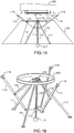
- FIGS. 1A and 1B schematically illustrate one of the principles of the invention.
- the figure 1A is a sectional view and the figure 1B is a perspective view.
- the figures show a satellite 100 having an interface 101 to the handling system 110.
- the handling system is located (eg folded or deployed or stored) in a storage space 120.
- the storage space 120 can be any type of housing, cavity, space, cache, shelter, protection or environment, suitable for storing the mechanism.
- the storage space can be a cone (or "interface cone").
- the storage space can be a cylinder or a rectangular housing (or any other geometric shape).
- the storage space can be rigid or deformable.
- the handling system 110 comprises a fixed supporting structure 111, a threaded rod 112, a nut 113, several articulated bars (parts of several "arms") 114 and 115, several appendages or gripping terminations 116, a rotary actuator 117 (by example an electric motor) and an articulated junction 118.
- an “arm” within the meaning of the invention does not comprise motorization or actuation means (an arm comprises articulated bars, ie more or less rigid bars interacting with each other by means of junctions or joints, usually fixed).
- the geometry (i.e. the shape) of the arms or bars can be very variable, the number too (two or three or more).
- the arms may be rigid in some embodiments but flexible and / or flexible arms may be used in other embodiments.
- the actuator 117 is generally rotary (e.g. revolution motor) but certain embodiments can use pneumatic and / or linear actuators of the piston type.
- the rotary actuator may include (for example) a rotating motor which drives a rotating screw, which itself drives a nut.
- a rotating motor which drives a rotating screw, which itself drives a nut.
- the use of a "roller screw" (according to its usual name) may be recommended (said screw includes a single screw and a roller nut).
- a linear actuator to move the nut in one direction or another; the screw-nut type link will then be replaced by a slide link.
- the invention can generally use any device for driving the nut in a vertical direction.
- the fixed supporting structure 111 is secured to the transfer vehicle also carrying the cone.
- the fixed structure is generally rigid but can be elastic in certain embodiments.
- Materials which can be used for these structural parts include (but are not limited to) aluminum, titanium, steel or alloys.
- Composite materials can also be used (eg carbon composites, etc.).
- the central threaded rod 112 has one end which is fixed to the outlet of the actuator 117 and another end which has a pivot connection with the fixed supporting structure, a threaded nut 113 guided by the threaded rod and several arms 114, which can be composed of articulated bars 114 and 115 also articulated at their interfaces on the nut and on the support structure.
- the mechanism includes three arms (114, 115).
- a three-arm mechanism represents a (currently) interesting compromise between weight and stability of the grip, taking into account current industrial requirements and constraints (for example choice of materials, economic criteria).
- a two-arm mechanism remains however possible (for example if the mode of contact between the space object and the handling system allows it with sufficient robustness and / or reliability).
- a mechanism with more than 3 arms is also possible, at the cost of additional mechanical parts and ultimately weight, although each arm can possibly be resized (for example lightened).
- Gripping appendages or terminations 116 can use a wide variety of means.
- the gripping means can use (including in combination): hooks (for example passive and / or motorized), pliers, claws, appendages (for example magnetic or electromagnetic), suction systems, glue systems, etc.
- the figure 2A illustrates an example of storage of the satellite handling system according to a particular embodiment.
- the figure shows the satellite handling system in a configuration stored in an interface cone 120.
- the storage space or interface cone 120 is of the ACU (Payload Adapter) type.
- ACU Payload Adapter
- An ACU typically has two parts: one part that stays on the launcher and another part that stays on the satellite. In some embodiments, only one part is required (i.e. one of the two elements to be connected does not require specific attachment means).
- the cap is released as soon as the launcher leaves the atmosphere.
- the ACU-satellite assembly is separated by cutting, generally using a pyrotechnic cord.
- the figure 2B illustrates the handling system in a collapsed or stored configuration, while the figure 2C represents this same system in a deployed or unfolded configuration.
- the figure 3A shows a configuration in which the arms are arranged in parallelograms and the arms are terminated by gripping devices or appendages 310 making it possible to maintain a substantially constant orientation.
- the figure 3B illustrates an alternative embodiment comprising curved arms 330 to optimize the grip opening while avoiding collisions with or in the storage cone.
- the figure 3C illustrates an alternative embodiment comprising several subsets 340 (for example three, distributed radially at regular angular intervals, so as to come "catch” or “capture” ie grasp and maintain the interface of the targeted space object.
- -sets 340 allow in particular to "lock” (and respectively to "unlock") the space object to be manipulated.
- Each sub-assembly 340 is composed of a plate 341, an articulated roller support 342 and at least two rollers 343.
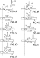
- FIGS. 4A to 4I schematically illustrate the operation of a sub-assembly by detailing the main steps for locking and unlocking a space object.
- Steps 4A to 4E illustrate the locking or the capture or the seizure of the space object by an alternative interface of the manipulation system according to the invention.
- the interface 101 of the space object (100, 400) and the appendix (116, 340) of the manipulation system 110 according to the invention approach each other (the movement is relative).
- the interface of the satellite 101 is placed on the plate 341.
- the two elements come together radially.
- the satellite interface then slides under the upper roller and the upper roller rolls along the vertical (or inclined) part of the satellite interface which rotates the roller support.
- the lower roller then comes into contact with the underside of the satellite interface.
- step 4D still under the effect of the radial approximation of the interface and the appendix, the lower roller raises the satellite interface while the upper roller guides it vertically.
- step 4E the upper roller locks in the angle formed by the satellite interface. The whole stabilizes at equilibrium under the effect of the horizontal actuation of the two elements.
- Steps 4F to 4I illustrate the unlocking or the dropping or the releasing or the grasping or the release of the space object by said variant interface of the manipulation system according to the invention.
- step 4F the subsets move away radially: the space object is no longer "tight".
- the satellite interface then descends guided by the rollers.
- step 4G the interface of the satellite 400 lands on the plate 341.
- step 4H the subassemblies continue to move apart, gradually releasing the interface of the satellite.
- step 4I the satellite interface is fully released and the satellite can then evolve freely.
- a program can be used to control the manipulation system according to the invention.
- the program can control or regulate the manipulation of the space object by slaving the single actuator (according to the two directions of rotation).
- sensors or “sensors” can be used and make it possible to locate the space object, to adjust the approach speed, to determine one or more points of contact with the space object and possibly measure the different pressures at the different contact points.
- Complementary means can make it possible to simulate the grasping of the space object, to take into account or anticipate the relative movements specific to the space object (as well as the relative maneuvers or movements specific to the transport vehicle) and thus to adjust or optimize the unfolding and folding operations of the articulated structure in order to optimize or ultimately regulate the capture of the space object.
- the Figures 5A and 5B illustrate certain aspects relating to the rotation of the rotary actuator.
- the relative actuator can operate in two directions of rotation (ie trigonometric direction and direction anti-trigonometric).
- the articulated bars With the configuration of the articulated bars according to the invention, it is possible to use one and the same direction of rotation to deploy the structure and also to grasp the spatial object (and possibly also lock said object).
- This configuration is illustrated in Figures 5A and 5B .
- the figure 5A shows the deployment of the folded structure when the rotary actuator starts to rotate in the 500 direction. Held by the bars 510, the bars 520 unfold and come out of the storage space 530.
- the figure 6 illustrates an improvement of the invention.
- the architecture of the articulated bars can indeed arrange interior spaces useful for implementing many services or functions towards the spatial object (e.g. food, repair, assistance, etc.).
- a fuel supply function can be implemented. It is emphasized that the improvement described below is not limited to the supply of fuel: it can be carried out, in substitution or in addition, the establishment of electrical type connections and / or data exchanges via cables and / or various other fluids (oxygen, etc.).
- the system for manipulating a space object so comprises additional three stages (610, 620, 630) or trays associated with the articulated structure. These trays can be full or hollowed out.
- the number of three floors is not essential: only one “interior” floor can be added.
- the different additional stages or sets of articulated bars can be combined in different ways.
- the sets of articulated bars and / or the stages being coupled ie being dependent on each other in some of their movements
- the displacement and / or blocking of one can cause the other to move and / or block.
- the precise geometrical configuration e.g. via flexible pivots 610) allows various ranges of dynamic behaviors (delay effect, etc.)
- the first stage 610 can for example be used to transmit the vertical translations transmitted from the single actuator.
- the second stage 620 makes it possible (among other aspects) to guide or channel or restrict or limit or control the movement in space of the fuel supply pipes or fittings (the figure shows that the pipe 601 passes through the recess of the second stage, without being able to become tangled in the device according to the invention).
- the second stage or tray may include guide means adapted to guide one or more pipes to one or more valves external to the system for handling a space object.
- the guide means may in particular comprise one or more protective cylinders. Other guiding means are possible.
- the first stage and the second stage can be merged and constitute only a single stage.
- the third stage 630 makes it possible to ensure the connection between the supply pipes and the adapted interfaces present on the space or satellite object for the transfer of fuel, by allowing for example the setting in fluid connection between valves 641 and 642.
- Specific embodiments can provide very specific stages 3 (blocking by lugs, independent motorization, etc.)
- stage 1 Under the actuation of a geared motor, stage 1 rises, while flexible connecting rods and pivots maintain a mechanical force on stage 2. Stage 1 activates stage 2 which proceeds to enter the space object; the two stages then push stage 3 on which are fixed filling valves. This stage 3 is guided by a system of parallelogram connecting rods and flexible pivots, allowing it to move vertically. Result of the successive movements of the different stages, the valves are guided to interfaces (for example satellite supply interfaces).
- interfaces for example satellite supply interfaces
- flexible pivots 611 can make it possible to connect the stages 1 and 2.
- any collision shocks can be absorbed by these flexible pivots.
- the plates Under the action of a gear motor rotating in the same direction as during deployment, the plates can be closed to block the satellite using a self-locking gripping system.
- the various sets of articulated bars (the handling system and the system carrying the feed plate) ie the stages (610, 620, 630) are deployed or folded by the same actuator implemented for the system for manipulating a space object according to the invention.
- this mode of advantageous embodiment in that it requires a minimum number of mechanical parts and is therefore robust against breakdowns.
- system carrying the feed plate (for example stage 3) can be motorized by a system independent of the single actuator implemented for the handling system according to the invention.
- This mode of implementation notably avoids the possibility of a single point of failure.
- the deployment is ensured by a single actuator which is constituted by a geared motor, a screw and a nut with balls or with rollers.
- the geared motor actuates for example a rotating screw, which has the effect of translating the first stage 610 and the second stage 620 in vertical translation (upwards in the figure), thanks to the nut linked to stage 1.
- the second stage 620 being linked to the first stage 610 by a bar system with flexible pivots 611, it translates vertically in the same way.
- the second stage 620 actuates the articulated arms (via 621) which, thanks to their special kinematics, separate the plates (e.g. 310).
- the valves 641 and 642 are automatically aligned by a guide system 629.
- a specific stage 3 can be composed of a fixed plate and a turntable on which the valves are mounted.
- a valve self-alignment system can then be fitted on the turntable.
- Such a system can use rollers 631 rolling on a cam, the cam being fixed on the satellite interface; thus, depending on the starting position, the turntable will rotate a maximum of 90 ° to align.
- ease loops (not shown) may advantageously "absorb" the rotation.
- the turntable of stage 3 may include a rotary interface on which the shelf will come to bear.
- valves Under the action of the gearmotor, the valves, now aligned with their satellite interfaces, can be connected or connected. Different types of connections can facilitate these connections.
- the manipulation system comprises specific stacking elements, allowing for example the gripping of a spatial object in a “secure” manner.
- a specifically adapted stage 3 rolling platform could be engaged with the screw and be blocked in translation by lugs.
- said screw may have to "let go” on the turntable; the guidance system of the stage 3 considered can then resume a position of equilibrium and free the turntable from the pins.
- the present invention can be implemented using hardware and / or software elements.
- a method of servo-control of the mechanism can include different steps to manage or regulate the operations of deployment / folding of the articulated structure (i.e. locking / unlocking of a space object).
- Computer code instructions can make it possible, for example when executed on a computer, to carry out said operations.
- One or more steps of the method can therefore be associated with a computer program product and / or with a computer-readable medium.
- Said support can be electronic, magnetic, optical or electromagnetic.
Landscapes
- Engineering & Computer Science (AREA)
- Remote Sensing (AREA)
- Aviation & Aerospace Engineering (AREA)
- Manipulator (AREA)
Description
L'invention concerne le domaine des satellites et en particulier celui de leur transport dans l'espace.The invention relates to the field of satellites and in particular that of their transport in space.
De nombreuses manipulations de satellites se déroulent dans l'espace. Par exemple, des satellites anciens peuvent être désorbités, des satellites peuvent être transférés vers de nouvelles orbites, d'autres encore peuvent être ravitaillés ou bien réparés.Many manipulations of satellites take place in space. For example, old satellites can be desorbed, satellites can be transferred to new orbits, still others can be refueled or repaired.
La conception et la fabrication effective de véhicules spécifiques, i.e. dédiés au transport de satellites, s'est développée très récemment. Les solutions envisagées connues à ce jour se fondent généralement sur l'utilisation de bras articulés. Ces solutions présentent de nombreux inconvénients. Un "bras articulé" selon l'état de la technique est un bras asservi, utilisant généralement de nombreux actuateurs aux articulations (afin de permettre autant de degrés de liberté). Chaque actuateur est associé à une probabilité de panne si bien que la fiabilité globale d'un bras articulé est problématique. Le stockage d'un bras (par exemple au lancement) implique un besoin de gerbage significatif, qui n'est pas toujours possible techniquement ou économiquement. Ce stockage est de plus associé à un point de panne unique, qui n'est pas toujours acceptable. Enfin, un bras articulé peut être difficile à piloter ou à tout le moins peut impliquer des efforts de programmation significatifs.The design and actual manufacture of specific vehicles, ie dedicated to the transport of satellites, has developed very recently. The solutions considered known to date are generally based on the use of articulated arms. These solutions have many drawbacks. A "articulated arm" according to the state of the art is a servo arm, generally using numerous actuators at the joints (in order to allow as many degrees of freedom). Each actuator is associated with a probability of failure so that the overall reliability of an articulated arm is problematic. The storage of an arm (for example at launch) implies a significant stacking requirement, which is not always technically or economically possible. This storage is also associated with a single point of failure, which is not always acceptable. Finally, an articulated arm can be difficult to control or at the very least can involve significant programming efforts.
Le document
Il existe un besoin industriel pressant pour des méthodes et des systèmes améliorés, en particulier fiables, pour la manipulation de satellites dans l'espace.There is a pressing industrial need for improved and particularly reliable methods and systems for handling satellites in space.
Selon l'invention, un système de manipulation d'un objet spatial dans l'espace est défini dans la revendication 1. Des modes de réalisation sont définis dans les revendications 2 à 14.According to the invention, a system for manipulating a space object in space is defined in
Selon l'invention, une méthode pour manipuler un objet spatial dans l'espace est définie dans la revendication 15. Un mode de réalisation est défini dans la revendication 16.According to the invention, a method for manipulating a spatial object in space is defined in claim 15. An embodiment is defined in claim 16.
Différents aspects et avantages de l'invention vont apparaitre en appui de la description d'un mode préféré d'implémentation de l'invention mais non limitatif, avec référence aux figures ci-dessous :
- Les
figures 1A et 1B illustrent schématiquement un des principes de l'invention; - Les
figures 2A, 2B et 2C illustrent un exemple de stockage du système de manipulation d'un satellite selon un mode de réalisation particulier; - Les
figures 3A, 3B et 3C illustrent des variantes de mises en œuvre; - Les
figures 4A à 4I illustrent schématiquement le fonctionnement d'un sous-ensemble en détaillant les principales étapes de verrouillage et de déverrouillage d'un objet spatial; - Les
figures 5A et 5B illustrent certains aspects relatifs à la rotation de l'actionneur rotatif ; - La
figure 6 illustre un perfectionnement de l'invention.
- The
Figures 1A and 1B schematically illustrate one of the principles of the invention; - The
Figures 2A, 2B and 2C illustrate an example of storage of the satellite handling system according to a particular embodiment; - The
Figures 3A, 3B and 3C illustrate alternative implementations; - The
Figures 4A to 4I schematically illustrate the operation of a sub-assembly by detailing the main steps for locking and unlocking a space object; - The
Figures 5A and 5B illustrate certain aspects relating to the rotation of the rotary actuator; - The
figure 6 illustrates an improvement of the invention.
La description des modes de réalisation de l'invention se déroule généralement dans l'espace, i.e. à gravité nulle. Toutefois, la force de gravitation demeure négligeable par rapport aux forces mécaniques présentement mises en œuvre, si bien que les diverses actions ou opérations ou manipulations décrites ici peuvent s'observer à terre (modulo quelques adaptations sans conséquence sur la nature de l'invention; par exemple l'objet spatial ne flotte pas mais est arrimé de quelque manière).The description of the embodiments of the invention generally takes place in space, ie at zero gravity. However, the gravitational force remains negligible compared to the mechanical forces presently implemented, so that the various actions or operations or manipulations described here can be observed on the ground (modulo some adaptations without consequence on the nature of the invention; for example the space object does not float but is stowed in some way).
Un objet spatial peut être un satellite ou une portion de satellite (artificiel ou naturel), un déchet, un outil, un élément ou portion de station spatiale, un instrument de mesure, un autre véhicule de transport de satellite, une portion de combinaison d'astronaute ou bien encore un étage lanceur.A space object may be a satellite or a portion of a satellite (artificial or natural), waste, a tool, an element or portion of a space station, a measuring instrument, another satellite transport vehicle, a portion of a combination of astronaut or even a launcher stage.
Les
De manière générale, l'espace de stockage 120 peut être tout type de logement, cavité, espace, cache, abri, protection ou environnement, convenant au stockage du mécanisme. Dans un cas particulier avantageux, l'espace de stockage peut être un cône (ou "cône d'interface"). Dans d'autres modes de réalisation, l'espace de stockage peut être un cylindre ou un logement parallélépipédique (ou de toute autre forme géométrique). L'espace de stockage peut être rigide ou bien déformable.In general, the
Le système de manipulation 110 comprend une structure fixe porteuse 111, une tige filetée 112, une noix 113, plusieurs barres articulées (parties de plusieurs "bras") 114 et 115, plusieurs appendices ou terminaisons de préhension 116, un actionneur rotatif 117 (par exemple un moteur électrique) et une jonction articulée 118.The
Un "bras" au sens de l'invention ne comprend pas de motorisation ou de moyens d'actuation (un bras comprend des barres articulées, i.e. des barres plus ou moins rigides en interaction les unes avec les autres par l'entremise de jonctions ou articulations, généralement fixes). La géométrie (i.e. la forme) des bras ou barres peut-être très variable, le nombre aussi (deux ou trois ou plus). Les bras peuvent être rigides dans certains modes de réalisation mais des bras souples et/ou flexibles peuvent être utilisés dans d'autres modes de réalisation.An “arm” within the meaning of the invention does not comprise motorization or actuation means (an arm comprises articulated bars, ie more or less rigid bars interacting with each other by means of junctions or joints, usually fixed). The geometry (i.e. the shape) of the arms or bars can be very variable, the number too (two or three or more). The arms may be rigid in some embodiments but flexible and / or flexible arms may be used in other embodiments.
L'actionneur 117 est généralement rotatif (e.g. moteur à révolution) mais certains modes de réalisation peuvent utiliser des actionneurs pneumatiques et/ou linéaires de type piston. Dans un mode de réalisation, l'actionneur rotatif peut comprendre (par exemple) un moteur en rotation qui entraîne une vis en rotation, qui elle-même entraîne un écrou. L'utilisation d'une "vis à rouleaux" (selon son nom usuel) peut être préconisée (ladite vis comprend une vis simple et un écrou à rouleaux). Dans d'autres modes de réalisation, il est possible d'utiliser une vis et un écrou standard ou bien encore une vis à billes. Il est également possible d'utiliser un actionneur linéaire pour faire déplacer la noix dans un sens ou dans un autre; la liaison de type vis-écrou sera alors remplacée par une liaison glissière. L'invention peut utiliser de manière générale tout dispositif permettant d'entraîner la noix selon une direction verticale.The
Dans un mode de réalisation, la structure fixe porteuse 111 est arrimée au véhicule de transfert portant également le cône.In one embodiment, the fixed supporting
La structure fixe est généralement rigide mais peut être élastique dans certains modes de réalisation. Les matériaux qui peuvent être utilisés pour ces pièces de structures comprennent (mais ne sont pas limitées à) l'aluminium, le titane, l'acier ou des alliages. Des matériaux composites peuvent également être utilisés (e.g. composites carbones, etc).The fixed structure is generally rigid but can be elastic in certain embodiments. Materials which can be used for these structural parts include (but are not limited to) aluminum, titanium, steel or alloys. Composite materials can also be used (eg carbon composites, etc.).
La tige filetée centrale 112 possède une extrémité qui est fixée à la sortie de l'actionneur 117 et une autre extrémité qui présente une liaison pivot avec la structure fixe porteuse, une noix taraudée 113 guidée par la tige filetée et de plusieurs bras 114, lesquels peuvent être composés de barres articulées 114 et 115 également articulés à leurs interfaces sur la noix et sur la structure porteuse.The central threaded
Dans un mode de réalisation, le mécanisme comprend trois bras (114, 115). Un mécanisme à trois bras représente un compromis (actuellement) intéressant entre poids et stabilité de la préhension, compte tenu des exigences et contraintes industrielles actuelles (par exemple choix de matériaux, critères économiques).In one embodiment, the mechanism includes three arms (114, 115). A three-arm mechanism represents a (currently) interesting compromise between weight and stability of the grip, taking into account current industrial requirements and constraints (for example choice of materials, economic criteria).
Un mécanisme à deux bras reste toutefois possible (par exemple si le mode de contact entre l'objet spatial et le système de manipulation le permet avec suffisamment de robustesse et/ou de fiabilité). Un mécanisme à plus de 3 bras est également possible, au prix d'un surcroît de pièces mécaniques et in fine de poids, bien que chaque bras puisse possiblement être redimensionné (par exemple allégé).A two-arm mechanism remains however possible (for example if the mode of contact between the space object and the handling system allows it with sufficient robustness and / or reliability). A mechanism with more than 3 arms is also possible, at the cost of additional mechanical parts and ultimately weight, although each arm can possibly be resized (for example lightened).
Les appendices ou terminaisons de préhension 116 peuvent utiliser une grande variété de moyens. Par exemple, les moyens de préhension peuvent utiliser (y compris en combinaison): des crochets (par exemple passifs et/ou motorisés), des pinces, des griffes, des appendices (par exemple magnétiques ou électromagnétiques), des systèmes d'aspiration, des systèmes à colle, etc.Gripping appendages or
La
Dans un mode de réalisation, l'espace de stockage ou cône d'interface 120 est de type ACU (Adaptateur Charge Utile). Au lancement, chaque satellite est fixé sur un support. Ce support est appelé Adaptateur Charge Utile (ACU, Upper adapter et Lower adapter). Un ACU comprend généralement deux parties: une partie qui reste sur le lanceur et une autre partie qui reste sur le satellite. Dans certains modes de réalisation, une seule partie est requise (i.e. un des deux éléments à connecter ne requiert pas de moyens d'attache spécifiques). La coiffe est larguée dès que le lanceur quitte l'atmosphère. Lors de la dernière phase du vol, la séparation de l'ensemble ACU-satellite se fait par découpe, généralement grâce à un cordon pyrotechnique.In one embodiment, the storage space or
La
Les
La
La
La
Chaque sous-ensemble 340 est composé d'un plateau 341, d'un support de galets articulé 342 et de au moins deux galets 343.Each sub-assembly 340 is composed of a plate 341, an articulated
Les
Les étapes 4A à 4E illustrent le verrouillage ou la capture ou la saisie de l'objet spatial par une variante d'interface du système de manipulation selon l'invention. A l'étape 4A, l'interface 101 de l'objet spatial (100, 400) et l'appendice (116, 340) du système de manipulation 110 selon l'invention se rapprochent l'un de l'autre (le mouvement est relatif). A l'étape 4B, l'interface du satellite 101 est posée sur le plateau 341. A l'étape 4C, les deux éléments (interface et appendice) se rapprochent radialement. L'interface satellite se glisse alors sous le galet supérieur et le galet supérieur roule le long de la partie verticale (ou inclinée) de l'interface satellite ce qui fait pivoter le support de galet. Le galet inférieur entre alors en contact avec la face inférieure de l'interface satellite. A l'étape 4D, toujours sous l'effet du rapprochement radial de l'interface et de l'appendice, le galet inférieur soulève l'interface satellite tandis que le galet supérieur le guide verticalement. A l'étape 4E, le galet supérieur se cale dans l'angle formé par l'interface satellite. L'ensemble se stabilise à l'équilibre sous l'effet de l'actuation horizontale des deux éléments.Steps 4A to 4E illustrate the locking or the capture or the seizure of the space object by an alternative interface of the manipulation system according to the invention. In step 4A, the
Les étapes 4F à 4I illustrent le déverrouillage ou le largage ou le lâchage ou la dessaisie ou la libération de l'objet spatial par ladite variante d'interface du système de manipulation selon l'invention.Steps 4F to 4I illustrate the unlocking or the dropping or the releasing or the grasping or the release of the space object by said variant interface of the manipulation system according to the invention.
A l'étape 4F, les sous-ensembles s'éloignent radialement : l'objet spatial n'est plus "serré". L'interface du satellite descend alors guidée par les galets. A l'étape 4G, l'interface du satellite 400 se pose sur le plateau 341. A l'étape 4H, les sous-ensembles continuent de s'écarter, libérant petit à petit l'interface du satellite. A l'étape 4I, l'interface satellite est entièrement libérée et le satellite peut alors évoluer librement.In step 4F, the subsets move away radially: the space object is no longer "tight". The satellite interface then descends guided by the rollers. In step 4G, the interface of the
Un programme (suite d'instructions) ou logiciel peut servir à asservir le système de manipulation selon l'invention. En particulier, le programme peut contrôler ou réguler la manipulation de l'objet spatial en asservissant l'actuateur unique (selon les deux sens de rotation). Dans certains modes de réalisation, des capteurs (ou "senseurs") peuvent être utilisés et permettre de localiser l'objet spatial, d'ajuster la vitesse d'approche, de déterminer un ou plusieurs points de contact avec l'objet spatial et éventuellement de mesurer les différentes pressions aux différents points de contact. Des moyens complémentaires (par exemple de vision par ordinateur) peuvent permettre de simuler la saisie de l'objet spatial, de prendre en compte ou d'anticiper les mouvements relatifs propres de l'objet spatial (ainsi que les manœuvres ou mouvements relatifs propres au véhicule de transport) et ainsi d'ajuster ou d'optimiser les opérations de dépliement et de repliement de la structure articulée afin d'optimiser ou de réguler in fine la saisie de l'objet spatial.A program (sequence of instructions) or software can be used to control the manipulation system according to the invention. In particular, the program can control or regulate the manipulation of the space object by slaving the single actuator (according to the two directions of rotation). In certain embodiments, sensors (or “sensors”) can be used and make it possible to locate the space object, to adjust the approach speed, to determine one or more points of contact with the space object and possibly measure the different pressures at the different contact points. Complementary means (for example of computer vision) can make it possible to simulate the grasping of the space object, to take into account or anticipate the relative movements specific to the space object (as well as the relative maneuvers or movements specific to the transport vehicle) and thus to adjust or optimize the unfolding and folding operations of the articulated structure in order to optimize or ultimately regulate the capture of the space object.
Les
La
L'architecture des barres articulées peut en effet aménager des espaces intérieurs utiles pour implémenter de nombreuses services ou fonctions envers l'objet spatial (e.g. alimentation, réparation, assistance, etc).The architecture of the articulated bars can indeed arrange interior spaces useful for implementing many services or functions towards the spatial object (e.g. food, repair, assistance, etc.).
En particulier, une fonction d'alimentation en carburant peut être implémentée. Il est souligné que le perfectionnement décrit ci-après n'est pas limité à l'approvisionnement en carburant: il peut être procédé, en substitution ou en complément, à l'établissement de connections de type électrique et/ou d'échanges de données via des câbles et/ou de divers autres fluides (oxygène, etc).In particular, a fuel supply function can be implemented. It is emphasized that the improvement described below is not limited to the supply of fuel: it can be carried out, in substitution or in addition, the establishment of electrical type connections and / or data exchanges via cables and / or various other fluids (oxygen, etc.).
Dans un mode de réalisation et selon le perfectionnement de l'invention, le système de manipulation d'un objet spatial comprend de manière additionnelle trois étages (610, 620, 630) ou plateaux associés à la structure articulée. Ces plateaux peuvent être pleins ou évidés. Le nombre de trois étages n'est pas indispensable : un seul étage « intérieur » peut être ajouté.In one embodiment and according to the improvement of the invention, the system for manipulating a space object so comprises additional three stages (610, 620, 630) or trays associated with the articulated structure. These trays can be full or hollowed out. The number of three floors is not essential: only one “interior” floor can be added.
Les différents étages additionnels ou ensembles de barres articulées peuvent être associées de différentes manières. Dans certains modes de réalisation, les ensembles de barres articulées et/ou les étages étant couplés (i.e. étant dépendants l'un de l'autre dans certains de leurs déplacements), le déplacement et/ou le blocage de l'un (par exemple le système de préhension sur l'interface satellite) peut entraîner le déplacement et/ou le blocage de l'autre. La configuration géométrique précise (e.g. via les pivots flexibles 610) permet des gammes variées de comportements dynamiques (effet retard, etc)The different additional stages or sets of articulated bars can be combined in different ways. In certain embodiments, the sets of articulated bars and / or the stages being coupled (ie being dependent on each other in some of their movements), the displacement and / or blocking of one (for example the gripping system on the satellite interface) can cause the other to move and / or block. The precise geometrical configuration (e.g. via flexible pivots 610) allows various ranges of dynamic behaviors (delay effect, etc.)
Le premier étage 610 peut par exemple servir à transmettre les translations verticales transmises depuis l'actuateur unique.The
Le second étage 620 permet (entre autres aspects) de guider ou canaliser ou restreindre ou limiter ou contrôler le déplacement dans l'espace des tuyaux ou raccords d'alimentation en carburant (la figure montre que le tuyau 601 passe au travers de l'évidement du second étage, sans pouvoir de fait s'emmêler dans le dispositif selon l'invention). De manière générale, le second étage ou plateau peut comprendre des moyens de guidage adaptés à guider une ou plusieurs conduites vers une ou plusieurs vannes extérieures au système de manipulation d'un objet spatial. Les moyens de guidage peuvent notamment comprendre un ou plusieurs cylindres de protection. D'autres moyens de guidage sont possibles. Le premier étage et le second étage peuvent être fusionnés et ne constituer qu'un étage unique.The
Le troisième étage 630 permet d'assurer la connexion entre les tuyaux d'alimentation et les interfaces adaptées présentes sur l'objet spatial ou satellite pour le transfert de carburant, en permettant par exemple la mise en connexion fluidique entre des vannes 641 et 642. Des modes de réalisation spécifiques peuvent prévoir des étages 3 très spécifiques (blocage par ergots, motorisation indépendante, etc)The
Dynamiquement, un exemple de fonctionnement concerté des trois étages selon le perfectionnement de l'invention est illustré à la
Plus en détail, dans un mode de réalisation particulier, des pivots flexibles 611 peuvent permettre de relier les étages 1 et 2. Avantageusement, les éventuels chocs de collision peuvent être absorbés par ces pivots flexibles. Sous l'action d'un motoréducteur tournant dans le même sens que lors du déploiement, les plateaux peuvent se refermer pour bloquer le satellite selon un système de préhension autobloquant.In more detail, in a particular embodiment,
Dans un mode de réalisation, les différents ensembles de barres articulées (le système de manipulation et le système portant le plateau d'alimentation) i.e. les étages (610, 620, 630) sont déployés ou repliés par le même actuateur mis en œuvre pour le système de manipulation d'un objet spatial selon l'invention. Héritant du même avantage, ce mode de réalisation avantageux en ce qu'il requiert un nombre minimal de pièces mécaniques et est donc robuste aux pannes.In one embodiment, the various sets of articulated bars (the handling system and the system carrying the feed plate) ie the stages (610, 620, 630) are deployed or folded by the same actuator implemented for the system for manipulating a space object according to the invention. Inheriting the same benefit, this mode of advantageous embodiment in that it requires a minimum number of mechanical parts and is therefore robust against breakdowns.
Dans un autre mode de réalisation toutefois, le système portant le plateau d'alimentation (par exemple l'étage 3) peut être motorisé par un système indépendant de l'actuateur unique mis en œuvre pour le système de manipulation selon l'invention. Ce mode de mise en œuvre évite notamment la possibilité d'un point de panne unique.In another embodiment, however, the system carrying the feed plate (for example stage 3) can be motorized by a system independent of the single actuator implemented for the handling system according to the invention. This mode of implementation notably avoids the possibility of a single point of failure.
Dans un mode de réalisation, le déploiement est assuré par un actuateur unique qui est constitué par un motoréducteur, une vis et un écrou à billes ou encore à rouleaux. Le motoréducteur actionne par exemple une vis en rotation, ce qui a pour effet de translater le premier étage 610 et le second étage 620 en translation verticale (vers le haut sur la figure), grâce à l'écrou lié à l'étage 1. Le second étage 620 étant lié au premier étage 610 par un système à barres avec des pivots flexibles 611, il se translate verticalement de la même façon. Le second étage 620 actionne quant à lui les bras articulés (via 621) qui grâce à leur cinématique particulière, écartent les plateaux (e.g. 310).In one embodiment, the deployment is ensured by a single actuator which is constituted by a geared motor, a screw and a nut with balls or with rollers. The geared motor actuates for example a rotating screw, which has the effect of translating the
Dans un mode de réalisation, les vannes 641 et 642 sont automatiquement alignées par un système de guidage 629. Par exemple, un étage 3 spécifique peut être composé d'un plateau fixe et d'un plateau tournant sur lequel sont montées les vannes. Un système d'auto-alignement des vannes peut alors être aménagé sur le plateau tournant. Un tel système peut utiliser des galets 631 roulant sur une came, la came étant fixée sur l'interface satellite; ainsi, en fonction de la position de départ, le plateau tournant pivotera d'un maximum de 90° pour s'aligner. Dans un mode de réalisation, concernant les conduites ou tuyaux d'alimentation (« tubing »), des boucles d'aisance (non représentées) pourront avantageusement « absorber » la rotation. Dans un mode de réalisation particulier, le plateau tournant de l'étage 3 peut comprendre une interface rotative sur lequel l'étagel viendra s'appuyer.In one embodiment, the
Sous l'action du motoréducteur, les vannes maintenant alignées avec leurs interfaces satellite, peuvent venir se connecter ou se brancher. Différents types de connections peuvent faciliter ces branchements.Under the action of the gearmotor, the valves, now aligned with their satellite interfaces, can be connected or connected. Different types of connections can facilitate these connections.
Dans un développement, le système de manipulation selon l'invention comprend des éléments de gerbage spécifiques, permettant par exemple la saisie d'un objet spatial de manière « sécurisée ». Par exemple, un plateau roulant d'un étage 3 spécifiquement adapté pourra être en prise avec la vis et être bloqué en translation par des ergots. Pour se dégerber lors de l'actionnement du motoréducteur, ladite vis pourra être amenée à «lâcher prise» sur le plateau tournant; le système de guidage de l'étage 3 considéré pourra alors reprendre une position d'équilibre et libérer le plateau tournant des ergots.In a development, the manipulation system according to the invention comprises specific stacking elements, allowing for example the gripping of a spatial object in a “secure” manner. For example, a specifically adapted
La présente invention peut s'implémenter à partir d'éléments matériel et/ou logiciel. En particulier, une méthode d'asservissement du mécanisme peut comprendre différentes étapes pour gérer ou réguler les opérations de déploiement/repliement de la structure articulée (i.e. de verrouillage/déverrouillage d'un objet spatial). Des instructions de code informatique peuvent permettre, par exemple lorsqu'exécutées sur un ordinateur, de réaliser lesdites opérations. Une ou plusieurs étapes de la méthode peuvent par suite être associées à un produit programme d'ordinateur et/ou à un support lisible par ordinateur. Ledit support peut être électronique, magnétique, optique ou électromagnétique.The present invention can be implemented using hardware and / or software elements. In particular, a method of servo-control of the mechanism can include different steps to manage or regulate the operations of deployment / folding of the articulated structure (i.e. locking / unlocking of a space object). Computer code instructions can make it possible, for example when executed on a computer, to carry out said operations. One or more steps of the method can therefore be associated with a computer program product and / or with a computer-readable medium. Said support can be electronic, magnetic, optical or electromagnetic.
Claims (15)
- System (110) for manipulating a space object (100) in space, the system comprising an articulated structure,
said articulated structure comprising a single actuator (117) configured to control, equally, the deployment of said articulated structure in space, the gripping of the space object and the folding down of said articulated structure;
the manipulation system (110) comprising a fixed supporting structure (111) and a central threaded rod (112), said central threaded rod (112) having a first end fixed to the output of the actuator (117) and a second end having a pivot link with the fixed supporting structure (111), the manipulation system further comprising a tapped whorl (113) guided by the central threaded rod and sets of articulated bars (114, 115) held by pivot links at their interfaces on the tapped whorl (113) and on the fixed supporting structure (111);
first articulated bars (114) of said sets being terminated by a gripping device (116, 340), characterized in that at least one gripping device (116, 340) comprises a plate (341), at least two rollers (343) and an articulated support (342) for said rollers. - System according to Claim 1, the manipulation system being configured to be stored in a folded-down configuration in an interface cone.
- System according to Claim 1, comprising three sets of articulated bars (114, 115).
- System according to Claim 1, comprising two sets of articulated bars (114, 115).
- System according to Claim 1, comprising four sets of articulated bars (114, 115).
- System according to Claim 1, in which one or more of the first articulated bars (114) have curved portions.
- System according to Claim 1, said at least one gripping device being arranged in such a way as to lock and/or unlock the space object by separation of said first articulated bars (114).
- System according to any one of the preceding claims, comprising at least one sensor for determining the position of the space object.
- System according to any one of the preceding claims, comprising at least one sensor for determining a contact and/or the contact pressure with the space object.
- System according to any one of the preceding claims, further comprising a first stage or plate controlled by the single actuator.
- System according to Claim 10, further comprising a second stage or plate associated with the first stage and/or with the articulated structure, participating in the gripping of the space object and/or making it possible to guide fuel supply pipes.
- System according to Claim 11, further comprising a third stage bearing fuel supply interfaces.
- System according to Claim 12, said third stage being motorized independently of the single actuator.
- Method for manipulating a space object (100) in space, the method comprising the steps of:- deploying an articulated structure by proceeding to rotate a single actuator (117) in a first direction of rotation; and- grasping the space object by folding down the articulated structure by proceeding to rotate the actuator in a second direction of rotation;said articulated structure comprising a single actuator (117) configured to control, equally, the deployment of said structure in space, the gripping of the space object and the folding down of said articulated structure;
said articulated structure comprising:- a fixed supporting structure (111) and a central threaded rod (112), said central threaded rod (112) having a first end fixed to the output of the actuator (117) and a second end having a pivot link with the fixed supporting structure (111), and- a tapped whorl (113) guided by the central threaded rod and sets of articulated bars (114, 115) held by pivot links at their interfaces on the tapped whorl (113) and on the fixed supporting structure (111); characterized in that,the second direction of rotation being identical to the first direction of rotation; and wherein:
when the actuator (117) starts to rotate in the direction of rotation (500), held by the first articulated bars (510) of said sets, the second articulated bars (520) of said sets are unfolded, and, still in the same direction of rotation (500) of the actuator (117), constrained by first articulated bars (510), the second articulated bars (520) are tightened so as to grasp the space object. - Method according to Claim 14, further comprising a step consisting of adjusting the rotation of the actuator as a function of data received from a sensor of position and/or of contact with the space object.
Applications Claiming Priority (2)
| Application Number | Priority Date | Filing Date | Title |
|---|---|---|---|
| FR1402388A FR3027587B1 (en) | 2014-10-24 | 2014-10-24 | HANDLING A SATELLITE IN SPACE |
| FR1501346A FR3027588B1 (en) | 2014-10-24 | 2015-06-26 | HANDLING A SATELLITE IN SPACE |
Publications (2)
| Publication Number | Publication Date |
|---|---|
| EP3012194A1 EP3012194A1 (en) | 2016-04-27 |
| EP3012194B1 true EP3012194B1 (en) | 2020-07-08 |
Family
ID=54291203
Family Applications (1)
| Application Number | Title | Priority Date | Filing Date |
|---|---|---|---|
| EP15190096.6A Active EP3012194B1 (en) | 2014-10-24 | 2015-10-16 | Manipulation of a satellite in space |
Country Status (1)
| Country | Link |
|---|---|
| EP (1) | EP3012194B1 (en) |
Families Citing this family (7)
| Publication number | Priority date | Publication date | Assignee | Title |
|---|---|---|---|---|
| FR3040978B1 (en) * | 2015-09-16 | 2017-10-06 | Airbus Defence & Space Sas | SPATIAL VEHICLE COMPRISING STACKS FOR FORMING A STACK, STACKING COMPRISING AT LEAST TWO SUCH VEHICLES PLACED IN A LAUNCHER AND METHOD OF LAGGING THE VEHICLES |
| CN108100312B (en) * | 2017-12-21 | 2023-08-25 | 星际漫步(北京)航天科技有限公司 | Satellite docking structure, docking satellite and docking method |
| CN108974394B (en) * | 2018-06-05 | 2024-05-10 | 中国科学院空间应用工程与技术中心 | Automatic locking and unlocking device for space active vibration isolation system |
| CN110406508B (en) * | 2019-08-21 | 2024-05-24 | 西南交通大学 | Electric vehicle shifter capable of double self-locking |
| FR3105179A1 (en) * | 2019-12-20 | 2021-06-25 | Airbus Defence And Space Sas | Shock absorbing mooring device to a satellite |
| EP4127544A4 (en) * | 2020-03-25 | 2024-03-27 | Orbit Fab, Inc. | Material transfer interfaces for space vehicles, and associated systems and methods |
| FR3109928B1 (en) * | 2020-05-11 | 2022-04-22 | Centre Nat Etd Spatiales | Improved Nano-Satellite Deployment Device |
Family Cites Families (4)
| Publication number | Priority date | Publication date | Assignee | Title |
|---|---|---|---|---|
| JPH0683978B2 (en) * | 1988-12-09 | 1994-10-26 | 石川島播磨重工業株式会社 | Fixing device |
| US5040748A (en) * | 1990-02-20 | 1991-08-20 | General Dynamics Corporation/Space Systems Division | Payload adapter ring |
| JPH0763245A (en) * | 1993-08-27 | 1995-03-07 | Toshiba Corp | Holding releasing device |
| CN103625656B (en) * | 2013-12-24 | 2015-08-19 | 哈尔滨工业大学 | A kind of Small-size spacecraft butt-joint mechanism |
-
2015
- 2015-10-16 EP EP15190096.6A patent/EP3012194B1/en active Active
Non-Patent Citations (1)
| Title |
|---|
| None * |
Also Published As
| Publication number | Publication date |
|---|---|
| EP3012194A1 (en) | 2016-04-27 |
Similar Documents
| Publication | Publication Date | Title |
|---|---|---|
| EP3012194B1 (en) | Manipulation of a satellite in space | |
| FR3027588A1 (en) | HANDLING A SATELLITE IN SPACE | |
| EP1786602B1 (en) | Parallel robot comprising means for setting in motion a mobile element split in two separate subassemblies | |
| EP0362342B1 (en) | Articulated device, for use in particular in the field of robotics | |
| EP2816723B1 (en) | Tripod mechanism with piezoelectric actuators | |
| WO1996007513A1 (en) | Telescopic system | |
| FR2909972A1 (en) | Vertical take-off and land aircraft for military application, has blocking unit selecting blocking configuration of arms in deployed position and releasing configuration of arms for authorizing arms to pass through folding position of arms | |
| WO2014076079A1 (en) | Hexapod system | |
| EP3962816B1 (en) | Device for damping docking to a satellite | |
| EP3145680A1 (en) | Pod for a parallel robot for controlling an object | |
| WO2015110433A1 (en) | Package pusher device | |
| EP3213999B1 (en) | Deployment and pointing device | |
| EP3045396B1 (en) | Pointing assembly of an instrument | |
| EP3401925A2 (en) | Cart for manipulating a container with regard to his connection to an isolator | |
| WO2016097388A1 (en) | Load-balancing device for articulated arm, associated load-handling apparatus and method | |
| EP3056435B1 (en) | Device for holding and releasing a remotely operated vehicle | |
| CA1308497C (en) | System for decontaminating the primary pipings and the water box of a nuclear plant steam generator | |
| FR3093021A1 (en) | High mobility land robot & high performance, thanks to its active arms with controlled compliance | |
| FR3050676B1 (en) | MANIPULATOR OF A PIECE | |
| WO2024089357A1 (en) | Three-degrees-of-freedom joint with force feedback | |
| FR2843952A1 (en) | Load handling yoke has stop foot to position yoke for reloading when emptied |
Legal Events
| Date | Code | Title | Description |
|---|---|---|---|
| PUAI | Public reference made under article 153(3) epc to a published international application that has entered the european phase |
Free format text: ORIGINAL CODE: 0009012 |
|
| AK | Designated contracting states |
Kind code of ref document: A1 Designated state(s): AL AT BE BG CH CY CZ DE DK EE ES FI FR GB GR HR HU IE IS IT LI LT LU LV MC MK MT NL NO PL PT RO RS SE SI SK SM TR |
|
| AX | Request for extension of the european patent |
Extension state: BA ME |
|
| 17P | Request for examination filed |
Effective date: 20161024 |
|
| RBV | Designated contracting states (corrected) |
Designated state(s): AL AT BE BG CH CY CZ DE DK EE ES FI FR GB GR HR HU IE IS IT LI LT LU LV MC MK MT NL NO PL PT RO RS SE SI SK SM TR |
|
| STAA | Information on the status of an ep patent application or granted ep patent |
Free format text: STATUS: EXAMINATION IS IN PROGRESS |
|
| 17Q | First examination report despatched |
Effective date: 20181030 |
|
| RIC1 | Information provided on ipc code assigned before grant |
Ipc: B64G 1/64 20060101AFI20191213BHEP Ipc: B64G 1/10 20060101ALN20191213BHEP |
|
| GRAP | Despatch of communication of intention to grant a patent |
Free format text: ORIGINAL CODE: EPIDOSNIGR1 |
|
| STAA | Information on the status of an ep patent application or granted ep patent |
Free format text: STATUS: GRANT OF PATENT IS INTENDED |
|
| INTG | Intention to grant announced |
Effective date: 20200128 |
|
| GRAS | Grant fee paid |
Free format text: ORIGINAL CODE: EPIDOSNIGR3 |
|
| GRAA | (expected) grant |
Free format text: ORIGINAL CODE: 0009210 |
|
| STAA | Information on the status of an ep patent application or granted ep patent |
Free format text: STATUS: THE PATENT HAS BEEN GRANTED |
|
| AK | Designated contracting states |
Kind code of ref document: B1 Designated state(s): AL AT BE BG CH CY CZ DE DK EE ES FI FR GB GR HR HU IE IS IT LI LT LU LV MC MK MT NL NO PL PT RO RS SE SI SK SM TR |
|
| REG | Reference to a national code |
Ref country code: CH Ref legal event code: EP Ref country code: AT Ref legal event code: REF Ref document number: 1288208 Country of ref document: AT Kind code of ref document: T Effective date: 20200715 |
|
| REG | Reference to a national code |
Ref country code: DE Ref legal event code: R096 Ref document number: 602015055331 Country of ref document: DE |
|
| REG | Reference to a national code |
Ref country code: IE Ref legal event code: FG4D Free format text: LANGUAGE OF EP DOCUMENT: FRENCH |
|
| RAP2 | Party data changed (patent owner data changed or rights of a patent transferred) |
Owner name: CENTRE NATIONAL D'ETUDES SPATIALES Owner name: THALES |
|
| REG | Reference to a national code |
Ref country code: DE Ref legal event code: R081 Ref document number: 602015055331 Country of ref document: DE Owner name: THALES, FR Free format text: FORMER OWNERS: CENTRE NATIONAL D'ETUDES SPATIALES, PARIS, FR; THALES, COURBEVOIE, FR |
|
| REG | Reference to a national code |
Ref country code: NL Ref legal event code: FP |
|
| REG | Reference to a national code |
Ref country code: LT Ref legal event code: MG4D |
|
| REG | Reference to a national code |
Ref country code: AT Ref legal event code: MK05 Ref document number: 1288208 Country of ref document: AT Kind code of ref document: T Effective date: 20200708 |
|
| PG25 | Lapsed in a contracting state [announced via postgrant information from national office to epo] |
Ref country code: HR Free format text: LAPSE BECAUSE OF FAILURE TO SUBMIT A TRANSLATION OF THE DESCRIPTION OR TO PAY THE FEE WITHIN THE PRESCRIBED TIME-LIMIT Effective date: 20200708 Ref country code: PT Free format text: LAPSE BECAUSE OF FAILURE TO SUBMIT A TRANSLATION OF THE DESCRIPTION OR TO PAY THE FEE WITHIN THE PRESCRIBED TIME-LIMIT Effective date: 20201109 Ref country code: SE Free format text: LAPSE BECAUSE OF FAILURE TO SUBMIT A TRANSLATION OF THE DESCRIPTION OR TO PAY THE FEE WITHIN THE PRESCRIBED TIME-LIMIT Effective date: 20200708 Ref country code: BG Free format text: LAPSE BECAUSE OF FAILURE TO SUBMIT A TRANSLATION OF THE DESCRIPTION OR TO PAY THE FEE WITHIN THE PRESCRIBED TIME-LIMIT Effective date: 20201008 Ref country code: GR Free format text: LAPSE BECAUSE OF FAILURE TO SUBMIT A TRANSLATION OF THE DESCRIPTION OR TO PAY THE FEE WITHIN THE PRESCRIBED TIME-LIMIT Effective date: 20201009 Ref country code: LT Free format text: LAPSE BECAUSE OF FAILURE TO SUBMIT A TRANSLATION OF THE DESCRIPTION OR TO PAY THE FEE WITHIN THE PRESCRIBED TIME-LIMIT Effective date: 20200708 Ref country code: NO Free format text: LAPSE BECAUSE OF FAILURE TO SUBMIT A TRANSLATION OF THE DESCRIPTION OR TO PAY THE FEE WITHIN THE PRESCRIBED TIME-LIMIT Effective date: 20201008 Ref country code: AT Free format text: LAPSE BECAUSE OF FAILURE TO SUBMIT A TRANSLATION OF THE DESCRIPTION OR TO PAY THE FEE WITHIN THE PRESCRIBED TIME-LIMIT Effective date: 20200708 Ref country code: FI Free format text: LAPSE BECAUSE OF FAILURE TO SUBMIT A TRANSLATION OF THE DESCRIPTION OR TO PAY THE FEE WITHIN THE PRESCRIBED TIME-LIMIT Effective date: 20200708 |
|
| PG25 | Lapsed in a contracting state [announced via postgrant information from national office to epo] |
Ref country code: PL Free format text: LAPSE BECAUSE OF FAILURE TO SUBMIT A TRANSLATION OF THE DESCRIPTION OR TO PAY THE FEE WITHIN THE PRESCRIBED TIME-LIMIT Effective date: 20200708 Ref country code: RS Free format text: LAPSE BECAUSE OF FAILURE TO SUBMIT A TRANSLATION OF THE DESCRIPTION OR TO PAY THE FEE WITHIN THE PRESCRIBED TIME-LIMIT Effective date: 20200708 Ref country code: LV Free format text: LAPSE BECAUSE OF FAILURE TO SUBMIT A TRANSLATION OF THE DESCRIPTION OR TO PAY THE FEE WITHIN THE PRESCRIBED TIME-LIMIT Effective date: 20200708 Ref country code: IS Free format text: LAPSE BECAUSE OF FAILURE TO SUBMIT A TRANSLATION OF THE DESCRIPTION OR TO PAY THE FEE WITHIN THE PRESCRIBED TIME-LIMIT Effective date: 20201108 |
|
| REG | Reference to a national code |
Ref country code: DE Ref legal event code: R097 Ref document number: 602015055331 Country of ref document: DE |
|
| REG | Reference to a national code |
Ref country code: ES Ref legal event code: FG2A Ref document number: 2821915 Country of ref document: ES Kind code of ref document: T3 Effective date: 20210428 |
|
| PG25 | Lapsed in a contracting state [announced via postgrant information from national office to epo] |
Ref country code: DK Free format text: LAPSE BECAUSE OF FAILURE TO SUBMIT A TRANSLATION OF THE DESCRIPTION OR TO PAY THE FEE WITHIN THE PRESCRIBED TIME-LIMIT Effective date: 20200708 Ref country code: CZ Free format text: LAPSE BECAUSE OF FAILURE TO SUBMIT A TRANSLATION OF THE DESCRIPTION OR TO PAY THE FEE WITHIN THE PRESCRIBED TIME-LIMIT Effective date: 20200708 Ref country code: EE Free format text: LAPSE BECAUSE OF FAILURE TO SUBMIT A TRANSLATION OF THE DESCRIPTION OR TO PAY THE FEE WITHIN THE PRESCRIBED TIME-LIMIT Effective date: 20200708 Ref country code: RO Free format text: LAPSE BECAUSE OF FAILURE TO SUBMIT A TRANSLATION OF THE DESCRIPTION OR TO PAY THE FEE WITHIN THE PRESCRIBED TIME-LIMIT Effective date: 20200708 Ref country code: SM Free format text: LAPSE BECAUSE OF FAILURE TO SUBMIT A TRANSLATION OF THE DESCRIPTION OR TO PAY THE FEE WITHIN THE PRESCRIBED TIME-LIMIT Effective date: 20200708 |
|
| PLBE | No opposition filed within time limit |
Free format text: ORIGINAL CODE: 0009261 |
|
| STAA | Information on the status of an ep patent application or granted ep patent |
Free format text: STATUS: NO OPPOSITION FILED WITHIN TIME LIMIT |
|
| PG25 | Lapsed in a contracting state [announced via postgrant information from national office to epo] |
Ref country code: AL Free format text: LAPSE BECAUSE OF FAILURE TO SUBMIT A TRANSLATION OF THE DESCRIPTION OR TO PAY THE FEE WITHIN THE PRESCRIBED TIME-LIMIT Effective date: 20200708 |
|
| REG | Reference to a national code |
Ref country code: CH Ref legal event code: PL |
|
| 26N | No opposition filed |
Effective date: 20210409 |
|
| PG25 | Lapsed in a contracting state [announced via postgrant information from national office to epo] |
Ref country code: SK Free format text: LAPSE BECAUSE OF FAILURE TO SUBMIT A TRANSLATION OF THE DESCRIPTION OR TO PAY THE FEE WITHIN THE PRESCRIBED TIME-LIMIT Effective date: 20200708 Ref country code: LU Free format text: LAPSE BECAUSE OF NON-PAYMENT OF DUE FEES Effective date: 20201016 Ref country code: MC Free format text: LAPSE BECAUSE OF FAILURE TO SUBMIT A TRANSLATION OF THE DESCRIPTION OR TO PAY THE FEE WITHIN THE PRESCRIBED TIME-LIMIT Effective date: 20200708 |
|
| REG | Reference to a national code |
Ref country code: BE Ref legal event code: MM Effective date: 20201031 |
|
| PG25 | Lapsed in a contracting state [announced via postgrant information from national office to epo] |
Ref country code: SI Free format text: LAPSE BECAUSE OF FAILURE TO SUBMIT A TRANSLATION OF THE DESCRIPTION OR TO PAY THE FEE WITHIN THE PRESCRIBED TIME-LIMIT Effective date: 20200708 Ref country code: LI Free format text: LAPSE BECAUSE OF NON-PAYMENT OF DUE FEES Effective date: 20201031 Ref country code: CH Free format text: LAPSE BECAUSE OF NON-PAYMENT OF DUE FEES Effective date: 20201031 Ref country code: BE Free format text: LAPSE BECAUSE OF NON-PAYMENT OF DUE FEES Effective date: 20201031 |
|
| PG25 | Lapsed in a contracting state [announced via postgrant information from national office to epo] |
Ref country code: IE Free format text: LAPSE BECAUSE OF NON-PAYMENT OF DUE FEES Effective date: 20201016 |
|
| PG25 | Lapsed in a contracting state [announced via postgrant information from national office to epo] |
Ref country code: TR Free format text: LAPSE BECAUSE OF FAILURE TO SUBMIT A TRANSLATION OF THE DESCRIPTION OR TO PAY THE FEE WITHIN THE PRESCRIBED TIME-LIMIT Effective date: 20200708 Ref country code: MT Free format text: LAPSE BECAUSE OF FAILURE TO SUBMIT A TRANSLATION OF THE DESCRIPTION OR TO PAY THE FEE WITHIN THE PRESCRIBED TIME-LIMIT Effective date: 20200708 Ref country code: CY Free format text: LAPSE BECAUSE OF FAILURE TO SUBMIT A TRANSLATION OF THE DESCRIPTION OR TO PAY THE FEE WITHIN THE PRESCRIBED TIME-LIMIT Effective date: 20200708 |
|
| PG25 | Lapsed in a contracting state [announced via postgrant information from national office to epo] |
Ref country code: MK Free format text: LAPSE BECAUSE OF FAILURE TO SUBMIT A TRANSLATION OF THE DESCRIPTION OR TO PAY THE FEE WITHIN THE PRESCRIBED TIME-LIMIT Effective date: 20200708 |
|
| PGFP | Annual fee paid to national office [announced via postgrant information from national office to epo] |
Ref country code: NL Payment date: 20230925 Year of fee payment: 9 Ref country code: GB Payment date: 20230914 Year of fee payment: 9 |
|
| PGFP | Annual fee paid to national office [announced via postgrant information from national office to epo] |
Ref country code: FR Payment date: 20230921 Year of fee payment: 9 |
|
| PGFP | Annual fee paid to national office [announced via postgrant information from national office to epo] |
Ref country code: ES Payment date: 20231109 Year of fee payment: 9 |
|
| PGFP | Annual fee paid to national office [announced via postgrant information from national office to epo] |
Ref country code: IT Payment date: 20230926 Year of fee payment: 9 Ref country code: DE Payment date: 20230919 Year of fee payment: 9 |