EP3012186B1 - Dam for fuel tank and its use - Google Patents
Dam for fuel tank and its use Download PDFInfo
- Publication number
- EP3012186B1 EP3012186B1 EP14844193.4A EP14844193A EP3012186B1 EP 3012186 B1 EP3012186 B1 EP 3012186B1 EP 14844193 A EP14844193 A EP 14844193A EP 3012186 B1 EP3012186 B1 EP 3012186B1
- Authority
- EP
- European Patent Office
- Prior art keywords
- fuel tank
- extending
- elastic member
- lip seal
- extending portion
- Prior art date
- Legal status (The legal status is an assumption and is not a legal conclusion. Google has not performed a legal analysis and makes no representation as to the accuracy of the status listed.)
- Active
Links
- 239000002828 fuel tank Substances 0.000 title claims description 98
- 238000007789 sealing Methods 0.000 claims description 96
- 230000007246 mechanism Effects 0.000 claims description 63
- 239000000565 sealant Substances 0.000 claims description 38
- 239000011347 resin Substances 0.000 description 30
- 229920005989 resin Polymers 0.000 description 30
- 101100334009 Caenorhabditis elegans rib-2 gene Proteins 0.000 description 29
- 239000000463 material Substances 0.000 description 14
- 238000004381 surface treatment Methods 0.000 description 9
- 229920001971 elastomer Polymers 0.000 description 7
- 239000005060 rubber Substances 0.000 description 7
- 238000004519 manufacturing process Methods 0.000 description 5
- 238000003825 pressing Methods 0.000 description 5
- 230000008878 coupling Effects 0.000 description 4
- 238000010168 coupling process Methods 0.000 description 4
- 238000005859 coupling reaction Methods 0.000 description 4
- 239000002184 metal Substances 0.000 description 4
- 238000000465 moulding Methods 0.000 description 4
- 239000004033 plastic Substances 0.000 description 4
- 229920003023 plastic Polymers 0.000 description 4
- 229920000459 Nitrile rubber Polymers 0.000 description 3
- 239000000470 constituent Substances 0.000 description 2
- 239000000446 fuel Substances 0.000 description 2
- 238000000034 method Methods 0.000 description 2
- 239000004677 Nylon Substances 0.000 description 1
- 229930182556 Polyacetal Natural products 0.000 description 1
- 239000004699 Ultra-high molecular weight polyethylene Substances 0.000 description 1
- 239000000853 adhesive Substances 0.000 description 1
- 230000001070 adhesive effect Effects 0.000 description 1
- 238000011109 contamination Methods 0.000 description 1
- 230000006378 damage Effects 0.000 description 1
- 229920005560 fluorosilicone rubber Polymers 0.000 description 1
- 238000005304 joining Methods 0.000 description 1
- 229920001778 nylon Polymers 0.000 description 1
- 230000002093 peripheral effect Effects 0.000 description 1
- 229920006324 polyoxymethylene Polymers 0.000 description 1
- 239000004587 polysulfide sealant Substances 0.000 description 1
- 238000007788 roughening Methods 0.000 description 1
- 229920000785 ultra high molecular weight polyethylene Polymers 0.000 description 1
Images


Classifications
-
- B—PERFORMING OPERATIONS; TRANSPORTING
- B64—AIRCRAFT; AVIATION; COSMONAUTICS
- B64D—EQUIPMENT FOR FITTING IN OR TO AIRCRAFT; FLIGHT SUITS; PARACHUTES; ARRANGEMENTS OR MOUNTING OF POWER PLANTS OR PROPULSION TRANSMISSIONS IN AIRCRAFT
- B64D37/00—Arrangements in connection with fuel supply for power plant
- B64D37/02—Tanks
- B64D37/06—Constructional adaptations thereof
- B64D37/08—Internal partitioning
-
- B—PERFORMING OPERATIONS; TRANSPORTING
- B64—AIRCRAFT; AVIATION; COSMONAUTICS
- B64C—AEROPLANES; HELICOPTERS
- B64C3/00—Wings
- B64C3/34—Tanks constructed integrally with wings, e.g. for fuel or water
Definitions
- the present invention relates to an aircraft fuel tank dam.
- a fuel tank is installed on a main wing and so on.
- the fuel tank is formed by a plurality of structural components which constitute the main wing and so on.
- a fuel tank dam is disposed between the structural components in order to close a gap.
- a shape of the plurality of structural components of the aircraft is a complex shape in order to suppress an increase in weight while ensuring strength.
- a shape of the fuel tank dam is also likely to become a complex shape.
- Patent Literature 1 US 8,167,245 B1 ), which is regarded as the closest prior art disclosing the preamble of claim 1, a fuel dam is disclosed.
- This fuel dam has a seal dam member.
- the seal dam member has a first portion connected with a first body, a second portion connected with the first portion and being more flexible than the first portion, and a third portion connected with the second portion and connected with a second body.
- the second portion is bended to accommodate deflection between the first body and the second body.
- Patent Literature 2 JP 2006-153624 A
- the plug closes a rib opening part formed in a rib of a main wing when the leakage test is performed on a wing fuel tank of an aircraft.
- the plug for leakage test has a fitting member including a plate and an engaging means fixed to the plate and engaging with the rib opening part.
- the fitting member is configured to make the plate fit in the rib opening part from one side of the rib opening part.
- the plug for leakage test has a pressing member which is disposed on the other side of the rib opening part via the rib so as to oppose the fitting member. The pressing member is extended to a peripheral portion of the rib opening part.
- the plug for leakage test also has a compressible sealing member disposed to contact the pressing member and a coupling means coupling the fitting member and the pressing member.
- the fitting member is engaged with the rib via the engaging means and is supported by the rib.
- the sealing member is pressed by the pressing member to be deformed. Thereby, the sealing member closes the gap formed between the fitting member and the rib opening part.
- Patent Literature 3 ( WO 2011/145291 A1 ), technique relating to an occluding member for an opening formed in a panel which constitutes an outer surface of an aircraft is disclosed.
- an object of the present invention is to provide an aircraft fuel tank dam with which it is possible to enhance the sealing properties.
- An aircraft fuel tank dam is a fuel tank dam which closes a gap formed between a first structural component and a second structural component.
- the fuel tank dam includes: a first portion disposed on a first structural component side; a second portion disposed on a second structural component side; an elastic member supported by the first portion at one end while supported by the second portion at the other end, and closing a gap formed between the first portion and the second portion; and a sealing mechanism which seals between the first portion and the elastic member, wherein the sealing mechanism comprises a lip seal portion of the elastic member.
- the aircraft fuel tank dam with which it is possible to enhance the sealing properties is provided.
- FIG. 1 is the schematic view of a main wing 70 of an aircraft. As shown in Fig. 1 , outer shape of the main wing 70 is defined by a skin 3. In the main wing 70, fuel tanks 61 (61-1, 61-2) are provided. Moreover, in the main wing 70, a rib 2 is provided. The fuel tank 61-1 and the fuel tank 61-2 are separated from each other by the rib 2.
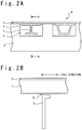
- Fig. 2A is the view when a part of a joint portion between the rib 2 and the skin 3 is viewed from the front.
- Fig. 2B is the cross-sectional view taken along line AA in Fig. 2A .
- the stringer 1 is joined to the skin 3 in order to enhance the strength.
- the stringer 1 extends along a first direction (longitudinal direction of the main wing 70) (see Fig. 2 B) .
- the rib 2 is arranged along a plane perpendicular to the first direction.
- a cutout portion 5 is formed at an end portion of the rib 2.
- the stringer 1 is disposed so as to pass through the cutout portion 5.
- a gap 4 is formed between the stringer 1 (a first structural component or a second structural component) and the rib 2 (the second structural component or the first structural component).
- the fuel tank dam according to the present embodiment is used for closing the gap 4.
- Fig. 3 is the perspective view of the fuel tank dam 7.
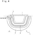
- Fig. 4 is the front view of the fuel tank dam 7.
- Fig. 4 is the view when the fuel tank dam 7 is viewed from a direction along the first direction. It should be noted that, in Fig. 4 , for reference, outer shape of the stringer 1 and outer shape of the rib 2 are illustrated by dotted lines.
- the fuel tank dam 7 includes a first portion 8, a second portion 9, an elastic member 10, and a sealing mechanisms 13 (13-1, 13-2).
- the first portion 8 is a portion which is fixed (joined) to the stringer 1.
- the second portion 9 is a portion which is fixed (joined) to the rib 2.
- the elastic member 10 is supported by being sandwiched by the first portion 8 at one end, and is supported by being sandwiched by the second portion 9 at the other end. A gap formed between the first portion 8 and second portion 9 is closed by the elastic member 10.
- the sealing mechanism 13-1 seals between the first portion 8 and the elastic member 10.
- the sealing mechanism 13-2 seals between the second portion 9 and the elastic member 10.
- the fuel tank dam 7 is fixed to the stringer 1 such that the stringer 1 is covered with the first portion 8.
- the first portion 8 is bonded to the stringer 1 via, for example, a sealant.
- the second portion 9 is fixed to the rib 2.
- the second portion 9 is also bonded to the rib 2 via, for example, a sealant.
- the gap between the first portion 8 and second portion 9 is closed by the elastic member 10.
- the gap 4 between the stringer 1 and the rib 2 is closed.
- other gap portions are closed by using sealant, adapter, etc. as will be explained in detail for embodiments described later.
- each structural component (the stringers 1, the rib 2) is deformed.
- a load is applied to the fuel tank dam 7.
- the elastic member 10 is provided between the first portion 8 and second portion 9, the load applied to the fuel tank dam 7 is absorbed and the destruction of the joint surface can be prevented.
- the sealing mechanism 13-1 is provided.
- the sealing properties between the elastic member 10 and the first portion 8 are enhanced as compared to a case in which the elastic member 10 is merely sandwiched by the first portion 8. It is also true for the sealing properties between the elastic member 10 and the second portion 9. In other words, the sealing properties of the fuel tank dam 7 are further enhanced.
- the first portion 8 is bended so as to cover the stringer 1 when viewed from the front.
- the first portion 8 includes a first member 11-1 and a second member 12-1.
- the first member 11-1 is a portion which is joined to the stringer 1 at the lower surface, and has an approximately plate shape.
- the second member 12-1 is disposed on the upper surface of the first member 11-1, and has an approximately plate shape.
- the first member 11-1 and the second member 12-1 are joined to each other via, for example, a sealant. Note that the first member 11-1 and the second member 12-1 sandwich one end of the elastic member 10 to support the elastic member 10.
- the second portion 9 has a shape for surrounding the first portion 8 via the gap to be closed by the elastic member 10 when viewed from the front.
- the second portion 9 has a first member 11-2 and a second member 12-2 like the first portion 8.
- the first member 11-2 has an approximately plate shape, and is joined to the rib 2 at the lower surface.
- the second member 12-2 also has an approximately plate shape, and is disposed on the first member 11-2.
- the other end of the elastic member 10 is sandwiched between the first member 11-2 and the second member 12-2, and the other end of the elastic member is supported by the first member 11-2 and the second member 12-2.
- first member 11-1 and the first member 11-2 are continuous at an end portion (see Fig. 4 ) in a case in which it is viewed from the front, and they constitute one member as a whole.
- the second member 12-1 and the second member 12-2 are continuous at an end portion in a case in which it is viewed from the front, and they constitute one member as a whole. That is, the fuel tank dam 7 has a structure in which the elastic member 10 is sandwiched between the first member 11 (11-1, 11-2) and the second member 12 (12-1, 12-2) and has a three layer structure.
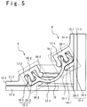
- FIG. 5 is the schematic view of the sealing mechanisms 13 (13-1, 13-2).
- the sealing mechanism 13-1 is formed by the one end of the elastic member 10 and a part of the first portion 8.
- the seal mechanism 13-2 is formed by the other end of the elastic member 10 and a part of the second portion 9.
- the sealing mechanism 13-1 includes a lip seal portion 15-1 which is formed at the one end of the elastic member 10.
- the lip seal portion 15-1 includes a first lip seal portion 19-1 and a second lip seal portion 20-1.
- the first lip seal portion 19-1 and the second lip seal portion 20-1 sandwich a part of the first portion 8.
- the sealing mechanism 13-1 includes a stopper portion 14-1, a first extending portion 16-1, a second extending portion 17-1, and a third extending 18-1 in addition to the lip seal portion 15-1.
- the stopper portion 14-1 is a part of the first member 11-1, and protrudes from the upper surface of the first member 11-1 (a surface opposite to the joint surface to be joined to the stringer 1) toward a second portion side.
- the first extending portion 16-1 is formed in the second member 12-1. Note that a portion contacting the first member 11-1 (a contact portion 21-1) is formed in the second member 12-1.
- the first extending portion 16-1 extends from an end of the contact portion 21-1 such that a space is formed between the first extending portion 16-1 and the first member 11-1 (more specifically, the stopper portion 14-1). More specifically, the first extending portion 16-1 extends so as to oppose the first member 11-1 (the stopper portion 14-1).
- the second extending portion 17-1 extends from the first extending portion 16-1 toward the first member 11-1 (the stopper portion 14-1).
- the above-mentioned first lip seal portion 19-1 and the second lip seal portion 20-1 sandwich the second extending portion 17-1.
- the third extending portion 18-1 extends, on a tip side of the second extending portion 17-1, from the first extending portion 16-1 toward the first member 11-1.
- the one end of the elastic member 10 root portion of the lip seal portion 15-1 is sandwiched between the third extending portion 18-1 and the stopper portion 14-1, and is supported by the third extending portion 18-1 and the stopper portion 14-1.
- the third extending portion 18-1 may not be necessarily provided.
- the sealing mechanism 13-2 has the same configuration as the sealing mechanism 13-1. That is, the sealing mechanism 13-2 includes a lip seal portion 15-2, a stopper portion 14-2, a first extending portion 16-2, a second extending portion 17-2, and a third extending portion 18-2.
- the second member 12-2 has a contact portion 21-2, and the first extending portion 16-2 extends from the contact portion 21-2 such that a space is formed between the first extending portion 16-2 and the first member 11-2 (the stopper portion 14-2).
- the lip seal portion 15-2 has a first lip seal portion 19-2 and a second lip seal portion 20-2.
- the second extending portion 17-2 is sandwiched between the first lip seal portion 19-2 and the second lip seal portion 20-2.
- the third extending portion 18-2 and the stopper portion 14-2 sandwich the other end of the elastic member 10, and support the other end of the elastic member 10.
- the lip seal portion 15 (15-1, 15-2) sandwiches the second extending portion 17 (17-1, 17-2).
- the fuel tank dam 7 is disposed at, for example, a boundary portion between the fuel tanks.
- a pressure difference is generated between both sides of the fuel tank dam 7.
- the lip seal portion 15 (15-1, 15-2) sandwiches the second extending portion 17 (17-1, 17-2).
- sealant adhesive
- the sealant may be applied between the end portion of the elastic member 10 and the first portion 8 (or the second portion 9).
- the lip seal portion 15 (15-1, 15-2) is provided, the sealant function can be realized without using the sealant and it is possible to prevent the contamination of the fuel tank.
- the elastic member 10 it is possible to use, for example, a rubber material.
- a rubber material it is possible to use, for example, fluorosilicone rubber, NBR (Nitrile butadiene rubber), hydrin rubber, hydrogenated nitrile rubber, another general rubber and so on.
- first member 11 11-1, 11-2) and the second member 12 (12-1, 12-2)
- plastic material it is possible to use, for example, nylon, ultra high molecular weight polyethylene, polyacetal and the like.
- sealant applied to each member or between members it is possible to use, for example, polysulfide sealant, another general sealant.
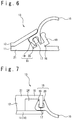
- Fig. 6 is the schematic view for illustrating a part of the sealing mechanism 13 of the fuel tank dam according to the present alternative embodiment. Note that, in the following explanation, for the purpose of simplifying the explanation, without distinguishing between the sealing mechanism 13-1 and the sealing mechanism 13-2, the sealing mechanism 13 will be explained as the sealing mechanism 13-1 or the sealing mechanism 13-2. It is true of the first extending portion 16 (16-1, 16-2), the second extending portion 17 (17-1 and 17-2) and the like.
- the first member 11 rather than the second member 12 has the first extending portion 16, the second extending portion 17, and the third extension portion 18.
- the first extending portion 16 extends from the contact portion (contact portion 21) of the first member 11 contacting the second member 12 so as to face the second member 12. Between the first extending portion 16 and the second member 12, the space is formed.
- the second extending portion 17 extends from the first extending portion 16 toward the second member 12. Like the above-mentioned embodiment, the first lip seal portion 19 and the second lip seal portions 20 sandwich the second extending portion 17.
- the third extension portion 18 extends, on a tip side of the second extending portion 17, from the first extending portion 16 toward the second member 12.
- the end portion of the elastic member 10 is sandwiched between the third extending portion 18 and the second member 12 and is supported by the third extending portion 18 and the second member 12.
- Fig. 7 is the schematic view of the sealing mechanism 13 according to the present embodiment.
- the sealing mechanism 13 has the first extending portion 16 and the second extending portion 17.
- the third extending portion 18 (see Fig. 5 ) is not provided.
- the first lip seal portion 19 and the second lip seal portion 20 sandwich the second extending portion 17.
- the elastic member 10 is sandwiched between the second extending portion 17 and the first member 11 at a region between the first lip seal portion 19 and the second lip seal portion 20, and is supported by the second extending portion 17 and the first member 11.
- the first member 11 rather than the second member 12 may have the first extending portion 16 and the second extending portion 17 like the alternative embodiment of the first embodiment.
- Fig. 8 is the schematic view for illustrating the sealing mechanism 13 according to the present embodiment. As shown in Fig. 8 , in the present embodiment, a support portion 22 is added to the sealing mechanism 13.
- the first lip seal portion 19 is disposed on the inner side of the second extending portion 17 in the space 24 formed between the first extending portion 16 and the first member 11.
- the second lip seal portion 20 is disposed on the outer side of the second extending portion 17, and the second extending portion 17 is sandwiched between the second lip seal portion 20 and the first lip seal portion 19.
- the support portion 22 is a part of the elastic member 10.
- the support portion 22 is disposed between the first lip seal portion 19 and a wall surface of the space 24.
- the first lip seal portion 19 is pushed against the second extending portion 17 by the support portion 22.
- the first lip seal portion 19 since the first lip seal portion 19 is pushed against the second extending portion 17 by the support portion 22, it is possible to seal between the first lip seal portion 19 and the second extending portion 17 more reliably. Thereby, the first lip seal portion 19 is hardly detached from the second extending portion 17, and the sealing properties are further enhanced.
- the first member 11 rather than the second member 12 may have the first extending portion 16 and the second extending portion 17 like the alternative embodiment of the first embodiment.
- the third extending portion 18 may be added like the first embodiment.
- Fig. 9 is the schematic view for illustrating the sealing mechanism 13 according to the present embodiment.
- the second lip seal portion 20 (see Fig. 8 ) is omitted from the third embodiment. That is, the elastic member 10 has a seal portion 23 (corresponding to the first lip seal portion 19 according to the third embodiment), and the support portion 22.
- the seal portion 23 and the support portion 22 are disposed on the inner side of the second extending portion 17 in the space 24 between the first extending portion 16 and the first member 11.
- the support portion 22 is disposed between the seal portion 23 and the wall surface of the space 24 such that the seal portion 23 is pushed against the second extending portion 17.
- the first member 11 rather than the second member 12 may have the first extending portion 16 and the second extending portion 17 like the alternative embodiment of the first embodiment.
- the third extending portion 18 may be added like the first embodiment.
- Fig. 10 is the schematic view for illustrating the sealing mechanism 13 according to the present embodiment.
- the support portion 22 includes a support member 25 provided separately from the elastic member 10.
- the support member 25 is disposed in the space 24.
- the support member 25 is, for example, an elastic body such as rubber.
- the support member 25 is disposed between the first lip seal portion 19 and the wall surface of the space 24 such that the first lip seal portion 19 is pushed against the second extending portion 17.
- the first member 11 rather than the second member 12 may have the first extending portion 16 and the second extending portion 17 like the alternative embodiment of the first embodiment.
- the third extending portion 18 may be added like the first embodiment.
- the second lip seal portion 20 may be omitted like the fourth embodiment.
- Fig. 11 is the schematic view for illustrating the sealing mechanism 13 according to the present embodiment.
- the support portion 22 includes a sealant portion 26 which is constituted by, for example, a curable type sealant etc.
- the sealant portion 26 is filled between the first lip seal portion 19 and the wall surface of the space 24. Thereby, the first lip seal portion 19 is pushed against the second extending portion 17.
- the first member 11 rather than the second member 12 may have the first extending portion 16 and the second extending portion 17 like the alternative embodiment of the first embodiment.
- the third extending portion 18 may be added like the first embodiment.
- the second lip seal portion 20 may be omitted like the fourth embodiment.
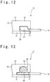
- Fig. 12 is the schematic view for illustrating the sealing mechanism 13 according to the present example.
- the sealing mechanism 13 includes the first extending portion 16, the second extending portion 17, and a compressed portion 27.
- the first extending portion 16 is included in the second member 12.
- the first extending portion 16 extends from the contact portion (contact portion 21) contacting the first member 11 such that the space 24 is formed between the first extending portion 16 and the first member 11.
- the second extending portion 17 extends from the first extending portion 16 toward the first member 11.
- the compressed portion 27 is formed at the one end of the elastic member 10, and swells than the other portion of the elastic member 10.
- the compressed portion 27 is compressed by being sandwiched between the extending portion 16 and the first member 11.
- the compressed portion 27 since the compressed portion 27 is provided, it is possible to enhance the sealing properties at a portion between the elastic member 10 and each portion (the first portion 8, the second portion 9), and it is possible to enhance the sealing properties of the fuel tank dam 7.
- first member 11 rather than the second member 12 may have the first extending portion 16 and the second extending portion 17 like the alternative embodiment of the first embodiment.
- Fig. 13 is the schematic view for illustrating the sealing mechanism 13 according to the present example.
- the sealing mechanism 13 includes the first extending portion 16, the second extending portion 17 and a compressed member 28.
- the first extending portion 16 is included in the second member 12.
- the first extending portion 16 extends from the contact portion (contact portion 21) contacting the first member 11 such that the space 24 is formed between the first extending portion 16 and the first member 11.
- the second extending portion 17 extends from the first extending portion 16 toward the first member 11.
- the compressed member 28 is constituted by, for example, a part of an O-ring made of rubber, and is disposed in the space 24. One end of the elastic member 10 is disposed in the space 24. The compressed member 28 is compressed and disposed between the one end of the elastic member 10 and the first extending portion 16. The one end of the elastic member 10 is sandwiched between the first member 11 and second member 12 via the compressed member 28.
- first member 11 rather than the second member 12 may have the first extending portion 16 and the second extending portion 17 like the alternative embodiment of the first embodiment.
- Fig. 14 is the schematic view for illustrating the sealing mechanism 13 according to the present example.
- the sealing mechanism 13 includes a recess 29, a recess 30, a first sealant portion 31, and a second sealant portion 32.
- the recess 30 is formed in the upper surface of the first member 11.
- the recess 29 is formed in the lower surface of the second member 12.
- the recess 30 and the recess 29 respectively are provided in portions which sandwich the elastic member 10.
- the first sealant portion 31 is filled in the recess 30.
- the first sealant portion 31 seals between the elastic member 10 and the first member 11.
- the second sealant portion 32 is filled in the recess 29.
- the second sealant portion 32 seals between the elastic member 10 and second member 12.
- the seal is provided between the elastic member 10 and each portion (the first portion 8, the second portion 9). Therefore, it is possible to enhance the sealing properties of the fuel tank dam 7.
- sealant used for the first sealant portion 31 and the second sealant portion 32 curable type sealant or non-curable sealant is used.
- material constituting each sealant portion (31, 32) it is possible to use the sealant that is described in the first embodiment.
- Fig. 15 is the schematic view for illustrating the sealing mechanism 13 according to the present example.
- the sealing mechanism 13 includes a labyrinth seal structure 33.
- the labyrinth seal structure 33 is formed by each portion (the first section 8, the second portion 9) and a shape of the end portion of the elastic member 10.
- the labyrinth seal structure 33 includes, an uneven structure formed in the upper surface of the first member 11, an uneven structure formed in the lower surface of the second member 12, and an uneven structure formed at the end portion of the elastic member 10.
- the uneven structure formed in the elastic member 10 is fitted to the uneven structures formed in the first member 11 and the second member 12. Note that a region between the uneven structure of the elastic member 10 and the uneven structures of the first member 11 and the second member 12 is filled with a sealant 71.
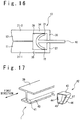
- Fig. 16 is the schematic view for illustrating the sealing mechanism 13 according to the present example.
- the sealing mechanism 13 includes a first member extending portion 36, a first member holding portion 37, a second member extending portion 34, a second member holding portion 35, a first lip seal portion 72, and a second lip seal portions 73.
- the first member extending portion 36 is included in the first member 11.
- a portion (a first member contact portion 21-1) contacting the second member 12 is formed, and the first member extending portion 36 extends from the first member contact portion 21-1 such that a space 38 is formed between the first member extending portion 36 and the second member 12.
- the first member holding portion 37 extends from the first member extending portion 36 toward the second member 12.
- the second member extending portion 34 is included in the second member 12.
- a portion (a second member contact portion 21-2) contacting the first member 11 is formed, and the second member extending portion 34 extends from the second member contact portion 21-2 such that the space 38 is formed between the second member extending portion 34 and the first member 11.
- the second member extending portion 34 extends so as to face the first member extending portion 36.
- the second member holding portion 35 extends from the second member extending portion 34 toward the first member 11.
- the elastic member 10 is sandwiched between the first member holding portion 37 and the second member holding portion 35.
- the first lip seal portion 72 and the second lip seal portions 73 are formed in the elastic member 10.
- the first lip seal portion 72 and the second lip seal portion 73 are disposed in the space 38.
- the first lip seal portion 72 is pushed against the first member 11 (the first member extending portion 36) in the space 38.
- the second lip seal portion 73 is pushed against the second member 12 (the second member extending portion 34) in the space 38.
- the first lip seal portion 72 seals between the elastic member 10 and the first member 11.
- the second lip seal portion 73 seals between the elastic member 10 and second member 12. Since the seals are formed at two locations, it is possible to enhance the sealing properties of the fuel tank dam 7.
- an adapter is placed on the stringer 1.
- the adapter is used to fill a gap formed between the stringer 1 and the fuel tank dam 7. That is, the adapter is placed such that an outer shape of the stringer 1 becomes a shape conformable to the fuel tank dam 7.
- the fuel tank dam 7 is fixed to the stringer 1 such that the first portion 8 covers the stringer 1 via the adapter.
- Fig. 17 is the perspective view for schematically illustrating an example of the stringer 1 and the adapter 42.
- the stringer 1 shown in Fig. 17 is a so-called I-cross-section stringer.
- the stringer 1 includes a first plate portion 39, a second plate portion 40, and a connecting portion 41.
- the first plate portion 39 has a flat plate shape, and is a portion that is bonded to the skin 3.
- the second plate portion 40 is disposed opposite to the first plate portion 39, and has a flat plate shape.
- the connecting portion 41 is a portion coupling the first plate portion 39 and the second plate portion 40 to each other. That is, the connecting portion 41 is joined to the first plate portion 39 at one end and is joined to the second plate portion 40 at the other end.
- the connecting portion 41 extends so as to connect a central portion of the first plate portion 39 and a central portion of the second plate portion 40 when viewed from a direction along the first direction.
- the connecting portion 41 has a flat plate shape, and is perpendicular to the first plate portion 39.
- the adapter 42 is placed so as to fill a recess formed by the first plate portion 39, the second plate portion 40 and the connecting portion 41. More specifically, the adapter 42 has a surface 44, a surface 43, a surface 45, a surface 46, and a surface 47.
- the surface 44 is a portion that is joined to the connecting portion 41.
- the surface 43 is a portion that is joined to the first plate portion 39.
- the surface 45 is a portion that is joined to the second plate portion 40.
- the surface 46 connects an end portion of the surface 43 and an end portion of the surface 45. When viewed from the front (when viewed from the direction along the first direction), a closed region is formed by the surface 44, the surface 43, the surface 45, and the surface 46.
- the surface 47 is a bottom surface, and is arranged to close the region formed by the surface 44, the surface 43, the surface 45 and the surface 46 when viewed from the front.
- Fig. 18 is the front view for illustrating the stringer 1 after the adapter 42 is disposed.
- the adapter 42 is bonded to the stringer 1 via a sealant 77.
- the adapter 42 and the stringer 1 may be joined by a fastener rather than the sealant 77 in order to increase the strength.
- the adapter 42 may be joined to the stringer 1.
- the adapter 42 is disposed in only one of the two recesses formed on both sides of the connecting portion 41.
- two adapters 42 are disposed in both of the recesses, respectively.
- Fig. 19 is the front view for illustrating the stringer 1 after the fuel tank dam 7 is joined.
- the adapters 42-1 and 42-2 are disposed on the stringer 1.
- the fuel tank dam 7 is joined to the stringer 1 such that the first portion 8 covers the stringer 1 via the adapters 42 (42-1, 42-2). That is, the first portion 8 is joined to the second plate portion 40 of the stringer 1, the surface 46-1 of the adapter 42-1 and the surface 46-2 of the adapter 42-2.
- the first portion 8 may be bent so as to form a part 8-1 corresponding to the second plate portion 40, a part 8-2 corresponding to the surface 46-1 and a part 8-3 corresponding to the surface 46-2, and may not be required to have a complex shape.
- Fig. 20 is the view for illustrating an arrangement of the fuel tank dam 7 in the case in which the J-cross-section stringer is used as the stringer 1.
- the stringer 1 includes the first plate portion 39, the second plate portion 40, and the connecting portion 41.
- the connecting portion 41 is connected to an end portion of the second plate portion 40 rather than the central portion of the second plate portion 40.
- one recess is formed on one side of the connecting portion 41.
- the adapter 42 is arranged only one side of the connecting portion 41.
- the fuel tank dam 7 is joined to the second plate portion 40 at the part 8-1, is joined to the surface 46 of the adapter 42 at the part 8-2, and is joined to the connecting portion 41 at the part 8-3.
- Fig. 21 is the view for illustrating the arrangement of the fuel tank dam 7 in the case in which the hat-type stringer is used as the stringer 1.
- the stringer 1 includes a pair of first plate portions 74 (74-1, 74-2), a second plate portion 75 and a pair of side portions 76 (76-1, 76-2).
- the pair of first plate portions 74 (74-1, 74-2) is a portion which is to be joined to the skin 3.
- the second portion 75 is disposed at a position away from the skin 3, and is parallel to the pair of first plate portion 74 (74-1, 74-2).
- the pair of side portions 76 (76-1, 76-2), respectively, connects the inner end portion of the pair of first plate portions 74 (74-1, 74-2) and an end portion of the second plate portion 75.
- the pair of side portions (76-1, 76-2) extends such that distance between the pair of side portions (76-1, 76-2) becomes larger toward the skin 3.
- the fuel tank dam 7 is joined to the second plate portion 75 at the part 8-1, is joined to the side portion 76-2 at the part 8-2, and is joined to the side portion 76-1 at the part 8-3.
- the adapter 42 As described above, according to the present example, by using the adapter 42 as needed, it is not required to create the fuel tank dam 7 having a complex shape as the fuel tank dam, and it is possible to reduce manufacturing costs.
- the fuel tank dam 7 according to the above-mentioned embodiments and examples may not necessarily be used.
- Another fuel tank dam may be used as long as it has configurations corresponding to the part 8-1, the part 8-2 and the part 8-3.
- FIG. 22 is the perspective view for schematically illustrating the adapter 42 according to the alternative example.
- each surface (the surface 43, the surface 44, and the surface 45), which is joined to the stringer 1, is longer in the first direction than the surface 46.
- Other configurations are the same as those of the adapter 42 shown in Fig. 17 .
- a fastener hole 78 for fastening the stringer 1 and the adapter 42 together by a fastener is formed in the surface 44. Although sufficient sealing properties can be obtained without fastening the fastener, the fastener may be used.
- Fig. 23 is the cross-sectional view for schematically illustrating the fuel tank dam 48 according to the present example.
- the fuel tank dam 48 includes an elastic member 49, and retainer members 50 (50-1, 50-2) made of metal or resin.
- the elastic member 49 is disposed so as to close the gap between the stringer 1 and the rib 2. More specifically, the elastic member 49 contacts the stringer 1 at one end, and contacts the rib 2 at the other end.
- a material of the elastic member 49 it is possible to use the same material as that of the elastic member 10 described in the first embodiment.
- the retainer member 50-1 is provided at one end of the elastic member 49, and is disposed such that the elastic member 49 is sandwiched between the retainer member 50-1 and the stringer 1.
- the retainer member 50-1 is provided for joining the elastic member 49 to the stringer 1 by a fastener 52-1. That is, the retainer member 50-1, the elastic member 49 and the stringer 1 are fastened by the fastener 52-1.
- the retainer member 50-2 is provided at the other end of the elastic member 49, and the elastic member 49 is sandwiched between the retainer member 50-2 and the rib 2.
- the retainer member 50-2, the elastic member 49 and the rib 2 are fastened by the fastener 52-2.
- retainer members 50 for example, a plastic material is used.
- the gap between the stringer 1 and the rib 2 is closed by two layer structure (the elastic member 49 and the retainer members 50-1, 50-2). Therefore, it is possible to further reduce the manufacturing costs.
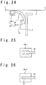
- Fig. 24 is the cross sectional view for schematically illustrating the fuel tank dam 53 according to the present example.
- the fuel tank dam 53 includes a first resin member 54-1, a second resin member 54-2 and an elastic member 55.
- the second resin member 54-2 and the rib 2 are fastened by a fastener 91.
- the first resin member 54-1 is a portion to be bonded to the stringer 1.
- the second resin member 54-2 is a portion to be bonded to the rib 2.
- the first resin member 54-1 and the second resin member 54-2 are bonded to the stringer 1 and the rib 2, respectively, via, for example, a sealant.
- the elastic member 55 As a material of the elastic member 55, it is possible to use the same material as that of the elastic member 10 described in the first embodiment, and, for example, a rubber material may be used.
- the elastic member 55 is embedded in the first resin member 54-1 at one end, and is embedded in the second resin member 54-2 at the other end. The gap between the stringer 1 and the rib 2 is closed by the elastic member 55.
- the elastic member 55, the first resin member 54-1 and the second resin member 54-2 are joined together by integral molding.
- the gap between the stringer 1 and the rib 2 is closed by two layer structure (the elastic member 49 and the resin members 54-1, 54-2). Therefore, it is possible to further reduce the manufacturing costs.
- the elastic member 55, the first resin member 54-1 and the second resin member 54-2 are joined by the integral molding. Therefore, it is possible to enhance the sealing properties at a joint portion between the elastic member 55 and the first resin member 54-1. It is true of the sealing properties between the elastic member 55 and the second resin member 54-2.
- Fig. 25 is the schematic view for illustrating the joint portion between the elastic member 55 and the first resin member 54-1 according to the alternative example. As shown in Fig. 25 , an uneven structure is formed at one end of the elastic member 55. The first resin member 54-1 covers the uneven structure. Although not shown in the drawings, it is true of the joint portion between the other end of the elastic member 55 and the second resin member 54-2.
- Fig. 26 is the schematic view for illustrating the joint portion between the elastic member 55 and the first resin member 54-1 according to the alternative example.
- a surface treatment portion 51 is formed at the end portion of the elastic member 55.
- the surface treatment portion 51 is a portion in which surface treatment such as roughening the surface is performed. It is true of the other end of the elastic member 55. Note that, ss the surface treatment, for example, satin finish is used.
- each resin member 54 (54-1, 54-2) is disposed and formed to cover both ends of the elastic member 55.
- the surface treatment portion 51 may be formed in each resin member 54 (54-1, 54-2) rather than the elastic member 55.
- the surface treatment is applied to a portion to be joined to the elastic member 55.
- the elastic member 55 is molded so as to be embedded in each resin member 54 (54-1, 54-2).
- Fig. 27A is the perspective view for schematically illustrating the fuel tank dam 90 according to the present example.
- Fig. 27B is the cross-sectional view for schematically illustrating the fuel tank dam 90.
- the fuel tank dam 90 includes a first portion 79, a second portion 80, and a third portion 81.
- the first portion 79, the second portion 80 and the third portion 81 are formed integrally, for example, using a plastic material.
- the first portion 79 is a portion to be joined to the stringer 1.
- the first portion 79 is bonded to the stringer 1 via, for example, a sealant.
- the second portion 80 is a portion to be joined to the rib 2.
- the second portion 80 is bonded to the rib 2 via, for example, a sealant like the first portion 79. Note that the second portion 80 is fastened to the rib 2 by a fastener (not shown).
- the third portion 81 is a portion coupling the first portion 79 and the second portion 80, and is provided so as to close a gap between the first portion 79 and the second portion 80.
- the third portion 81 includes a plurality of folded portions 82. That is, the third portion 81 has a bellows shape.
- the third portion 81 since the third portion 81 has the bellows shape, a load is absorbed by the third portion 81 even when the load is applied in accordance with deformation of the rib 2 or the stringer 1. As a result, break of joint surface between the fuel tank dam 90 and each structural component (rib 2, stringer 1) can be prevented, and it is possible to enhance the sealing properties.
Description
- The present invention relates to an aircraft fuel tank dam.
- In an aircraft, a fuel tank is installed on a main wing and so on. The fuel tank is formed by a plurality of structural components which constitute the main wing and so on. Regarding the fuel tank, there is a case in which a fuel tank dam is disposed between the structural components in order to close a gap.
- As the fuel tank dam, there is a case in which sheet metal components are used. However, in many cases, a shape of the plurality of structural components of the aircraft is a complex shape in order to suppress an increase in weight while ensuring strength. As a result, a shape of the fuel tank dam is also likely to become a complex shape. In the case of using the sheet metal components, it is necessary to prepare a large number of sheet metal components having complex shape, and manufacturing costs are increased.
- In Patent Literature 1 (
US 8,167,245 B1 ), which is regarded as the closest prior art disclosing the preamble ofclaim 1, a fuel dam is disclosed. This fuel dam has a seal dam member. The seal dam member has a first portion connected with a first body, a second portion connected with the first portion and being more flexible than the first portion, and a third portion connected with the second portion and connected with a second body. The second portion is bended to accommodate deflection between the first body and the second body. - Further, in Patent Literature 2 (
JP 2006-153624 A - Further, in Patent Literature 3 (
WO 2011/145291 A1 ), technique relating to an occluding member for an opening formed in a panel which constitutes an outer surface of an aircraft is disclosed. -
- Patent Literature 1:
US 8,167,245 B1 - Patent Literature 2:
JP 2006-153624 A - Patent Literature 3:
WO 2011/145291 A1 - Regarding the fuel tank dam, high sealing properties are required. Therefore, an object of the present invention is to provide an aircraft fuel tank dam with which it is possible to enhance the sealing properties.
- An aircraft fuel tank dam according to the present invention is a fuel tank dam which closes a gap formed between a first structural component and a second structural component. The fuel tank dam includes: a first portion disposed on a first structural component side; a second portion disposed on a second structural component side; an elastic member supported by the first portion at one end while supported by the second portion at the other end, and closing a gap formed between the first portion and the second portion; and a sealing mechanism which seals between the first portion and the elastic member, wherein the sealing mechanism comprises a lip seal portion of the elastic member.
- According to the present invention, the aircraft fuel tank dam with which it is possible to enhance the sealing properties is provided.
-
-
Fig. 1 is a schematic view of a main wing of an aircraft. -
Fig. 2A is a view when viewing a part of a rib from the front. -
Fig. 2B is a cross-sectional view taken along line AA inFig. 2A . -
Fig. 3 is a perspective view for illustrating a fuel tank dam according to a first embodiment. -
Fig. 4 is a front view of the fuel tank dam. -
Fig. 5 is a schematic view of a sealing mechanism. -
FIG. 6 is a schematic view of a sealing mechanism portion according to an alternative embodiment of the first embodiment. -
FIG. 7 is a schematic view of the sealing mechanism according to a second embodiment. -
FIG. 8 is a schematic view of the sealing mechanism according to a third embodiment. -
FIG. 9 is a schematic view of the sealing mechanism according to a fourth embodiment. -
FIG. 10 is a schematic view of the sealing mechanism according to a fifth embodiment. -
FIG. 11 is a schematic view of the sealing mechanism according to a sixth embodiment. -
FIG. 12 is a schematic view of the sealing mechanism according to a first example. -
FIG. 13 is a schematic view of the sealing mechanism according to an second example. -
FIG. 14 is a schematic view of the sealing mechanism according to a third example. -
FIG. 15 is a schematic view of the sealing mechanism according to a fourth example. -
FIG. 16 is a schematic view of the sealing mechanism according to an fifth example. -
Fig. 17 is a perspective view for schematically illustrating an example of a stringer and an adapter. -
Fig. 18 is a front view of the stringer after the adapter has been arranged. -
Fig. 19 is a front view of the stringer after the fuel tank dam is joined. -
Fig. 20 is a view for illustrating an arrangement of the fuel tank dam when a J-cross-section stringer is used. -
Fig. 21 is a view for illustrating an arrangement of the fuel tank dam when a hat-type stringer is used. -
Fig. 22 is a perspective view for schematically illustrating the adapter according to an alternative example. -
Fig. 23 is a cross-sectional view for schematically illustrating the fuel tank dam according to a seventh example. -
Fig. 24 is a cross-sectional view for schematically illustrating the fuel tank dam according to a eighth example. -
Fig. 25 is a schematic view for illustrating a joint portion between an elastic member and a first resin member according to a first alternative example of the eighth example. -
Fig. 26 is a schematic view for illustrating the joint portion between the elastic member and the first resin member according to a second alternative example of the eighth example. -
Fig. 27A is a perspective view for schematically illustrating the fuel tank dam according to a ninth example. -
Fig. 27B is a cross-sectional view for schematically illustrating the fuel tank dam. - With reference to the drawings, some embodiments and other examples will be explained below.
- At first, a fuel tank structure to which a fuel tank dam according to the present embodiment is applied will be explained.
Fig. 1 is the schematic view of amain wing 70 of an aircraft. As shown inFig. 1 , outer shape of themain wing 70 is defined by askin 3. In themain wing 70, fuel tanks 61 (61-1, 61-2) are provided. Moreover, in themain wing 70, arib 2 is provided. The fuel tank 61-1 and the fuel tank 61-2 are separated from each other by therib 2. -
Fig. 2A is the view when a part of a joint portion between therib 2 and theskin 3 is viewed from the front. In addition,Fig. 2B is the cross-sectional view taken along line AA inFig. 2A . As shown inFigs. 2A and Fig. 2B , thestringer 1 is joined to theskin 3 in order to enhance the strength. Thestringer 1 extends along a first direction (longitudinal direction of the main wing 70) (seeFig. 2 B) . - On the other hand, the
rib 2 is arranged along a plane perpendicular to the first direction. In addition, acutout portion 5 is formed at an end portion of therib 2. Thestringer 1 is disposed so as to pass through thecutout portion 5. - Note that, as shown in
Fig. 2A , at thecutout portion 5, agap 4 is formed between the stringer 1 (a first structural component or a second structural component) and the rib 2 (the second structural component or the first structural component). The fuel tank dam according to the present embodiment is used for closing thegap 4. - Next, a structure of the fuel tank dam will be explained.
Fig. 3 is the perspective view of thefuel tank dam 7. In addition,Fig. 4 is the front view of thefuel tank dam 7.Fig. 4 is the view when thefuel tank dam 7 is viewed from a direction along the first direction. It should be noted that, inFig. 4 , for reference, outer shape of thestringer 1 and outer shape of therib 2 are illustrated by dotted lines. - As shown in
Fig. 3 , thefuel tank dam 7 includes afirst portion 8, asecond portion 9, anelastic member 10, and a sealing mechanisms 13 (13-1, 13-2). Thefirst portion 8 is a portion which is fixed (joined) to thestringer 1. Thesecond portion 9 is a portion which is fixed (joined) to therib 2. Theelastic member 10 is supported by being sandwiched by thefirst portion 8 at one end, and is supported by being sandwiched by thesecond portion 9 at the other end. A gap formed between thefirst portion 8 andsecond portion 9 is closed by theelastic member 10. The sealing mechanism 13-1 seals between thefirst portion 8 and theelastic member 10. The sealing mechanism 13-2 seals between thesecond portion 9 and theelastic member 10. - As shown in
Fig. 4 , thefuel tank dam 7 is fixed to thestringer 1 such that thestringer 1 is covered with thefirst portion 8. Thefirst portion 8 is bonded to thestringer 1 via, for example, a sealant. Thesecond portion 9 is fixed to therib 2. Thesecond portion 9 is also bonded to therib 2 via, for example, a sealant. Note that the gap between thefirst portion 8 andsecond portion 9 is closed by theelastic member 10. Thus, thegap 4 between thestringer 1 and therib 2 is closed. Note that, other gap portions are closed by using sealant, adapter, etc. as will be explained in detail for embodiments described later. - There is a case in which each structural component (the
stringers 1, the rib 2) is deformed. As a result of deformation, a load is applied to thefuel tank dam 7. By the load, there is a possibility that a joint surface between thefuel tank dam 7 and each of the structural components (stringer 1, the rib 2) is destroyed. However, according to the above-mentioned configuration, since theelastic member 10 is provided between thefirst portion 8 andsecond portion 9, the load applied to thefuel tank dam 7 is absorbed and the destruction of the joint surface can be prevented. - In addition, in the
fuel tank dam 7 according to the present embodiment, the sealing mechanism 13-1 is provided. Thereby, the sealing properties between theelastic member 10 and thefirst portion 8 are enhanced as compared to a case in which theelastic member 10 is merely sandwiched by thefirst portion 8. It is also true for the sealing properties between theelastic member 10 and thesecond portion 9. In other words, the sealing properties of thefuel tank dam 7 are further enhanced. - Next, configuration of each part will be explained in detail.
- As shown in
Fig. 4 , thefirst portion 8 is bended so as to cover thestringer 1 when viewed from the front. Further, as shown inFig. 3 , thefirst portion 8 includes a first member 11-1 and a second member 12-1. The first member 11-1 is a portion which is joined to thestringer 1 at the lower surface, and has an approximately plate shape. The second member 12-1 is disposed on the upper surface of the first member 11-1, and has an approximately plate shape. The first member 11-1 and the second member 12-1 are joined to each other via, for example, a sealant. Note that the first member 11-1 and the second member 12-1 sandwich one end of theelastic member 10 to support theelastic member 10. - On the other hand, as shown in
Fig. 4 , thesecond portion 9 has a shape for surrounding thefirst portion 8 via the gap to be closed by theelastic member 10 when viewed from the front. As shown inFig. 3 , thesecond portion 9 has a first member 11-2 and a second member 12-2 like thefirst portion 8. The first member 11-2 has an approximately plate shape, and is joined to therib 2 at the lower surface. The second member 12-2 also has an approximately plate shape, and is disposed on the first member 11-2. The other end of theelastic member 10 is sandwiched between the first member 11-2 and the second member 12-2, and the other end of the elastic member is supported by the first member 11-2 and the second member 12-2. - Note that the first member 11-1 and the first member 11-2 are continuous at an end portion (see
Fig. 4 ) in a case in which it is viewed from the front, and they constitute one member as a whole. Similarly, the second member 12-1 and the second member 12-2 are continuous at an end portion in a case in which it is viewed from the front, and they constitute one member as a whole. That is, thefuel tank dam 7 has a structure in which theelastic member 10 is sandwiched between the first member 11 (11-1, 11-2) and the second member 12 (12-1, 12-2) and has a three layer structure. - Next, the sealing mechanisms 13 (13-1, 13-2) will be explained.
Fig. 5 is the schematic view of the sealing mechanisms 13 (13-1, 13-2). - The sealing mechanism 13-1 is formed by the one end of the
elastic member 10 and a part of thefirst portion 8. Similarly, the seal mechanism 13-2 is formed by the other end of theelastic member 10 and a part of thesecond portion 9. - The sealing mechanism 13-1 includes a lip seal portion 15-1 which is formed at the one end of the
elastic member 10. The lip seal portion 15-1 includes a first lip seal portion 19-1 and a second lip seal portion 20-1. The first lip seal portion 19-1 and the second lip seal portion 20-1 sandwich a part of thefirst portion 8. - More specifically, the sealing mechanism 13-1 includes a stopper portion 14-1, a first extending portion 16-1, a second extending portion 17-1, and a third extending 18-1 in addition to the lip seal portion 15-1.
- The stopper portion 14-1 is a part of the first member 11-1, and protrudes from the upper surface of the first member 11-1 (a surface opposite to the joint surface to be joined to the stringer 1) toward a second portion side.
- The first extending portion 16-1 is formed in the second member 12-1. Note that a portion contacting the first member 11-1 (a contact portion 21-1) is formed in the second member 12-1. The first extending portion 16-1 extends from an end of the contact portion 21-1 such that a space is formed between the first extending portion 16-1 and the first member 11-1 (more specifically, the stopper portion 14-1). More specifically, the first extending portion 16-1 extends so as to oppose the first member 11-1 (the stopper portion 14-1).
- The second extending portion 17-1 extends from the first extending portion 16-1 toward the first member 11-1 (the stopper portion 14-1). The above-mentioned first lip seal portion 19-1 and the second lip seal portion 20-1 sandwich the second extending portion 17-1.
- The third extending portion 18-1 extends, on a tip side of the second extending portion 17-1, from the first extending portion 16-1 toward the first member 11-1. The one end of the elastic member 10 (root portion of the lip seal portion 15-1) is sandwiched between the third extending portion 18-1 and the stopper portion 14-1, and is supported by the third extending portion 18-1 and the stopper portion 14-1.
- Note that the third extending portion 18-1 may not be necessarily provided.
- Note that the sealing mechanism 13-2 has the same configuration as the sealing mechanism 13-1. That is, the sealing mechanism 13-2 includes a lip seal portion 15-2, a stopper portion 14-2, a first extending portion 16-2, a second extending portion 17-2, and a third extending portion 18-2. The second member 12-2 has a contact portion 21-2, and the first extending portion 16-2 extends from the contact portion 21-2 such that a space is formed between the first extending portion 16-2 and the first member 11-2 (the stopper portion 14-2). The lip seal portion 15-2 has a first lip seal portion 19-2 and a second lip seal portion 20-2. The second extending portion 17-2 is sandwiched between the first lip seal portion 19-2 and the second lip seal portion 20-2. The third extending portion 18-2 and the stopper portion 14-2 sandwich the other end of the
elastic member 10, and support the other end of theelastic member 10. - When adopting the above-mentioned configuration, high sealing properties can be obtained since the lip seal portion 15 (15-1, 15-2) sandwiches the second extending portion 17 (17-1, 17-2). There is a case in which the
fuel tank dam 7 is disposed at, for example, a boundary portion between the fuel tanks. In such a case, there is a case in which a pressure difference is generated between both sides of thefuel tank dam 7. As a result, there is a case in which a force is applied to theelastic member 10 in a direction in which seal surfaces are separated. However, according to the present embodiment, the lip seal portion 15 (15-1, 15-2) sandwiches the second extending portion 17 (17-1, 17-2). Therefore, even when the force is applied to one portion of the first lip seal portion 19 (19-1, 19-2) and the second lip seal portion 20 (20-1, 20-2) so that the one portion is separated from the second extending portion 17 (17-1,17-2), a force is applied to the other lip seal portion so that the other lip seal portion is pushed toward the second extending portion 17 (17-1, 17-2). Thus, regardless of the pressure difference between both sides of thefuel tank dam 7, it is possible to maintain a sealing function. - Furthermore, it is conceivable to apply a sealant (adhesive) and so on between the
elastic member 10 and the first portion 8 (or the second portion 9) in order to realize the sealing function. In the present embodiment, the sealant may be applied between the end portion of theelastic member 10 and the first portion 8 (or the second portion 9). However, depending on a type of sealant, there is a possibility that an inner portion of the fuel tank is contaminated. In the present embodiment, since the lip seal portion 15 (15-1, 15-2) is provided, the sealant function can be realized without using the sealant and it is possible to prevent the contamination of the fuel tank. - Next, a constituent material of the
fuel tank dam 7 will be explained. - As the
elastic member 10, it is possible to use, for example, a rubber material. As the rubber material, it is possible to use, for example, fluorosilicone rubber, NBR (Nitrile butadiene rubber), hydrin rubber, hydrogenated nitrile rubber, another general rubber and so on. - As the first member 11 (11-1, 11-2) and the second member 12 (12-1, 12-2), it is possible to use, for example, a plastic material. As such a plastic material, it is possible to use, for example, nylon, ultra high molecular weight polyethylene, polyacetal and the like.
- As the sealant applied to each member or between members, it is possible to use, for example, polysulfide sealant, another general sealant.
- Next, an alternative embodiment of the present embodiment will be explained. In the above-mentioned embodiment, the explanation has been provided about the case in which the second member 12 (12-1, 12-2) has the first extending portion 16 (16-1, 16-2), the second extending portion 17 (17-1, 17-2), and the third extending portion 18 (18-1, 18-2). However, these configurations may be included in the first member 11 (11-1, 11-2) rather than in the second member 12 (12-1, 12-2). In the alternative embodiment, explanation will be provided in a case in which the first member 11 (11-1, 11-2) has the first extending portion 16 (16-1, 16-2), the second extending portion 17 (17-1, 17-2), and the third extending portion 18 (18-1, 18-2).
-
Fig. 6 is the schematic view for illustrating a part of thesealing mechanism 13 of the fuel tank dam according to the present alternative embodiment. Note that, in the following explanation, for the purpose of simplifying the explanation, without distinguishing between the sealing mechanism 13-1 and the sealing mechanism 13-2, thesealing mechanism 13 will be explained as the sealing mechanism 13-1 or the sealing mechanism 13-2. It is true of the first extending portion 16 (16-1, 16-2), the second extending portion 17 (17-1 and 17-2) and the like. - As shown in
Fig. 6 , in the present alternative embodiment, thefirst member 11 rather than thesecond member 12 has the first extendingportion 16, the second extendingportion 17, and thethird extension portion 18. The first extendingportion 16 extends from the contact portion (contact portion 21) of thefirst member 11 contacting thesecond member 12 so as to face thesecond member 12. Between the first extendingportion 16 and thesecond member 12, the space is formed. - The second extending
portion 17 extends from the first extendingportion 16 toward thesecond member 12. Like the above-mentioned embodiment, the firstlip seal portion 19 and the secondlip seal portions 20 sandwich the second extendingportion 17. - The
third extension portion 18 extends, on a tip side of the second extendingportion 17, from the first extendingportion 16 toward thesecond member 12. The end portion of theelastic member 10 is sandwiched between the third extendingportion 18 and thesecond member 12 and is supported by the third extendingportion 18 and thesecond member 12. - Regarding other respects, it is possible to adopt the same configuration as that of the above-mentioned embodiment. Therefore, detailed explanation is omitted.
- Even when adopting the configuration of the alternative embodiment, it is possible to obtain the high sealing properties like the above-mentioned embodiment.
- Subsequently, the second embodiment will be explained. In this embodiment, configuration of the
sealing mechanism 13 is changed from the first embodiment. Regarding other respects, since it is possible to adopt the same configuration as that of the first embodiment, detailed explanation is omitted. -
Fig. 7 is the schematic view of thesealing mechanism 13 according to the present embodiment. As shown inFig. 7 , thesealing mechanism 13 has the first extendingportion 16 and the second extendingportion 17. However, the third extending portion 18 (seeFig. 5 ) is not provided. The firstlip seal portion 19 and the secondlip seal portion 20 sandwich the second extendingportion 17. In addition, theelastic member 10 is sandwiched between the second extendingportion 17 and thefirst member 11 at a region between the firstlip seal portion 19 and the secondlip seal portion 20, and is supported by the second extendingportion 17 and thefirst member 11. - Even in the case in which the third extending
portion 18 is not provided like the present embodiment, it is possible to obtain the high sealing properties by adopting thelip seal portion 15. - Note that, in the present embodiment, the
first member 11 rather than thesecond member 12 may have the first extendingportion 16 and the second extendingportion 17 like the alternative embodiment of the first embodiment. - Next, the third embodiment will be explained. In this embodiment, configuration of the
sealing mechanism 13 is changed from the second embodiment. Regarding other respects, since it is possible to adopt the same configuration as that of the second embodiment, detailed explanation is omitted. -
Fig. 8 is the schematic view for illustrating thesealing mechanism 13 according to the present embodiment. As shown inFig. 8 , in the present embodiment, asupport portion 22 is added to thesealing mechanism 13. - In the present embodiment, the first
lip seal portion 19 is disposed on the inner side of the second extendingportion 17 in thespace 24 formed between the first extendingportion 16 and thefirst member 11. On the other hand, the secondlip seal portion 20 is disposed on the outer side of the second extendingportion 17, and the second extendingportion 17 is sandwiched between the secondlip seal portion 20 and the firstlip seal portion 19. - The
support portion 22 is a part of theelastic member 10. Thesupport portion 22 is disposed between the firstlip seal portion 19 and a wall surface of thespace 24. The firstlip seal portion 19 is pushed against the second extendingportion 17 by thesupport portion 22. - According to the present embodiment, since the first
lip seal portion 19 is pushed against the second extendingportion 17 by thesupport portion 22, it is possible to seal between the firstlip seal portion 19 and the second extendingportion 17 more reliably. Thereby, the firstlip seal portion 19 is hardly detached from the second extendingportion 17, and the sealing properties are further enhanced. - Note that, in the present embodiment, the
first member 11 rather than thesecond member 12 may have the first extendingportion 16 and the second extendingportion 17 like the alternative embodiment of the first embodiment. - Further, in the present embodiment, the third extending portion 18 (see
Fig. 5 ) may be added like the first embodiment. - Next, the fourth embodiment will be explained. In this embodiment, configuration of the
sealing mechanism 13 is changed from the third embodiment. Regarding other respects, since it is possible to adopt the same configuration as that of the third embodiment, detailed explanation is omitted. -
Fig. 9 is the schematic view for illustrating thesealing mechanism 13 according to the present embodiment. As shown inFig. 9 , in the present embodiment, the second lip seal portion 20 (seeFig. 8 ) is omitted from the third embodiment. That is, theelastic member 10 has a seal portion 23 (corresponding to the firstlip seal portion 19 according to the third embodiment), and thesupport portion 22. Theseal portion 23 and thesupport portion 22 are disposed on the inner side of the second extendingportion 17 in thespace 24 between the first extendingportion 16 and thefirst member 11. Thesupport portion 22 is disposed between theseal portion 23 and the wall surface of thespace 24 such that theseal portion 23 is pushed against the second extendingportion 17. - When adopting the configuration of this modified example, it is possible to push the
seal portion 23 against the second extendingportion 17 since thesupport portion 22 is provided. Therefore, it is possible to enhance the sealing properties even if the secondlip seal portion 20 is not provided. - Note that, in the present embodiment, the
first member 11 rather than thesecond member 12 may have the first extendingportion 16 and the second extendingportion 17 like the alternative embodiment of the first embodiment. - Further, in the present embodiment, the third extending portion 18 (see
Fig. 5 ) may be added like the first embodiment. - Subsequently, the fifth embodiment will be explained. In this embodiment, configuration of the
support portion 22 is changed from the third embodiment. Regarding other respects, since it is possible to adopt the same configuration as that of the third embodiment, detailed explanation is omitted. -
Fig. 10 is the schematic view for illustrating thesealing mechanism 13 according to the present embodiment. In the present embodiment, thesupport portion 22 includes asupport member 25 provided separately from theelastic member 10. Thesupport member 25 is disposed in thespace 24. Thesupport member 25 is, for example, an elastic body such as rubber. Thesupport member 25 is disposed between the firstlip seal portion 19 and the wall surface of thespace 24 such that the firstlip seal portion 19 is pushed against the second extendingportion 17. - When adopting the configuration of this modified example, it is possible to push the first
lip seal portion 19 against the second extendingportion 17 since thesupport member 25 is provided, and it is possible to enhance the sealing properties. - Note that, in the present embodiment, the
first member 11 rather than thesecond member 12 may have the first extendingportion 16 and the second extendingportion 17 like the alternative embodiment of the first embodiment. - Further, in the present embodiment, the third extending portion 18 (see
Fig. 5 ) may be added like the first embodiment. - Moreover, in the present embodiment, the second
lip seal portion 20 may be omitted like the fourth embodiment. - Subsequently, the sixth embodiment will be explained. In this embodiment, configuration of the
support portion 22 is changed from the third embodiment. Regarding other respects, since it is possible to adopt the same configuration as that of the third embodiment, detailed explanation is omitted. -
Fig. 11 is the schematic view for illustrating thesealing mechanism 13 according to the present embodiment. In the present embodiment, thesupport portion 22 includes asealant portion 26 which is constituted by, for example, a curable type sealant etc. Thesealant portion 26 is filled between the firstlip seal portion 19 and the wall surface of thespace 24. Thereby, the firstlip seal portion 19 is pushed against the second extendingportion 17. - When adopting the configuration of this modified example, it is possible to push the first
lip seal portion 19 against the second extendingportion 17 since thesealant portion 26 is provided, and it is possible to enhance the sealing properties. - Note that, in the present embodiment, the
first member 11 rather than thesecond member 12 may have the first extendingportion 16 and the second extendingportion 17 like the alternative embodiment of the first embodiment. - Further, in the present embodiment, the third extending portion 18 (see
Fig. 5 ) may be added like the first embodiment. - Moreover, in the present embodiment, the second
lip seal portion 20 may be omitted like the fourth embodiment. - Subsequently, the first example will be explained. In this example, configuration of the
sealing mechanism 13 is changed from the first embodiment. Regarding other respects, since it is possible to adopt the same configuration as that of the first embodiment, detailed explanation is omitted. -
Fig. 12 is the schematic view for illustrating thesealing mechanism 13 according to the present example. As shown inFig. 12 , thesealing mechanism 13 includes the first extendingportion 16, the second extendingportion 17, and acompressed portion 27. The first extendingportion 16 is included in thesecond member 12. The first extendingportion 16 extends from the contact portion (contact portion 21) contacting thefirst member 11 such that thespace 24 is formed between the first extendingportion 16 and thefirst member 11. The second extendingportion 17 extends from the first extendingportion 16 toward thefirst member 11. The compressedportion 27 is formed at the one end of theelastic member 10, and swells than the other portion of theelastic member 10. The compressedportion 27 is compressed by being sandwiched between the extendingportion 16 and thefirst member 11. - According to the present example, since the compressed
portion 27 is provided, it is possible to enhance the sealing properties at a portion between theelastic member 10 and each portion (thefirst portion 8, the second portion 9), and it is possible to enhance the sealing properties of thefuel tank dam 7. - Note that, in the present example, the
first member 11 rather than thesecond member 12 may have the first extendingportion 16 and the second extendingportion 17 like the alternative embodiment of the first embodiment. - Subsequently, the second example will be explained. In this example, configuration of the
sealing mechanism 13 is changed from the first embodiment. Regarding other respects, since it is possible to adopt the same configuration as that of the first embodiment, detailed explanation is omitted. -
Fig. 13 is the schematic view for illustrating thesealing mechanism 13 according to the present example. As shown inFig. 13 , thesealing mechanism 13 includes the first extendingportion 16, the second extendingportion 17 and acompressed member 28. The first extendingportion 16 is included in thesecond member 12. The first extendingportion 16 extends from the contact portion (contact portion 21) contacting thefirst member 11 such that thespace 24 is formed between the first extendingportion 16 and thefirst member 11. The second extendingportion 17 extends from the first extendingportion 16 toward thefirst member 11. - The
compressed member 28 is constituted by, for example, a part of an O-ring made of rubber, and is disposed in thespace 24. One end of theelastic member 10 is disposed in thespace 24. Thecompressed member 28 is compressed and disposed between the one end of theelastic member 10 and the first extendingportion 16. The one end of theelastic member 10 is sandwiched between thefirst member 11 andsecond member 12 via thecompressed member 28. - When adopting the configuration of this example, it is possible to enhance the sealing properties at both end portions of the
elastic member 10 since thecompressed member 28 is provided, and it is possible to enhance the sealing properties of thefuel tank dam 7. - Note that, in the present example, the
first member 11 rather than thesecond member 12 may have the first extendingportion 16 and the second extendingportion 17 like the alternative embodiment of the first embodiment. - Subsequently, the third example will be explained. In this example, configuration of the
sealing mechanism 13 is changed from the first embodiment. Regarding other respects, since it is possible to adopt the same configuration as that of the first embodiment, detailed explanation is omitted. -
Fig. 14 is the schematic view for illustrating thesealing mechanism 13 according to the present example. Thesealing mechanism 13 includes arecess 29, arecess 30, afirst sealant portion 31, and asecond sealant portion 32. Therecess 30 is formed in the upper surface of thefirst member 11. Therecess 29 is formed in the lower surface of thesecond member 12. Therecess 30 and therecess 29 respectively are provided in portions which sandwich theelastic member 10. Thefirst sealant portion 31 is filled in therecess 30. Thefirst sealant portion 31 seals between theelastic member 10 and thefirst member 11. Thesecond sealant portion 32 is filled in therecess 29. Thesecond sealant portion 32 seals between theelastic member 10 andsecond member 12. - According to the present example, at two positions, that is the
first sealant 31 portion and thesecond sealant portion 32, the seal is provided between theelastic member 10 and each portion (thefirst portion 8, the second portion 9). Therefore, it is possible to enhance the sealing properties of thefuel tank dam 7. - Note that, as the sealant used for the
first sealant portion 31 and thesecond sealant portion 32, curable type sealant or non-curable sealant is used. For example, as the material constituting each sealant portion (31, 32), it is possible to use the sealant that is described in the first embodiment. - Subsequently, the fourth example will be explained. In this example, configuration of the
sealing mechanism 13 is changed from the first embodiment. Regarding other respects, since it is possible to adopt the same configuration as that of the first embodiment, detailed explanation is omitted. -
Fig. 15 is the schematic view for illustrating thesealing mechanism 13 according to the present example. Thesealing mechanism 13 includes alabyrinth seal structure 33. Thelabyrinth seal structure 33 is formed by each portion (thefirst section 8, the second portion 9) and a shape of the end portion of theelastic member 10. - More specifically, the
labyrinth seal structure 33 includes, an uneven structure formed in the upper surface of thefirst member 11, an uneven structure formed in the lower surface of thesecond member 12, and an uneven structure formed at the end portion of theelastic member 10. The uneven structure formed in theelastic member 10 is fitted to the uneven structures formed in thefirst member 11 and thesecond member 12. Note that a region between the uneven structure of theelastic member 10 and the uneven structures of thefirst member 11 and thesecond member 12 is filled with asealant 71. - When adopting the configuration of the present example, it is possible to enhance the sealing properties between the
elastic member 10 and each portion (thefirst portion 8, the second portion 9) since thelabyrinth seal structure 33 is provided, and it is possible to enhance the sealing properties of thefuel tank dam 7. - Subsequently, the fifth example will be explained. In this example, configuration of the
sealing mechanism 13 is changed from the first embodiment. Regarding other respects, since it is possible to adopt the same configuration as that of the first embodiment, detailed explanation is omitted. -
Fig. 16 is the schematic view for illustrating thesealing mechanism 13 according to the present example. Thesealing mechanism 13 includes a firstmember extending portion 36, a firstmember holding portion 37, a secondmember extending portion 34, a secondmember holding portion 35, a firstlip seal portion 72, and a secondlip seal portions 73. - The first
member extending portion 36 is included in thefirst member 11. In thefirst member 11, a portion (a first member contact portion 21-1) contacting thesecond member 12 is formed, and the firstmember extending portion 36 extends from the first member contact portion 21-1 such that aspace 38 is formed between the firstmember extending portion 36 and thesecond member 12. The firstmember holding portion 37 extends from the firstmember extending portion 36 toward thesecond member 12. - The second
member extending portion 34 is included in thesecond member 12. In thesecond member 12, a portion (a second member contact portion 21-2) contacting thefirst member 11 is formed, and the secondmember extending portion 34 extends from the second member contact portion 21-2 such that thespace 38 is formed between the secondmember extending portion 34 and thefirst member 11. The secondmember extending portion 34 extends so as to face the firstmember extending portion 36. The secondmember holding portion 35 extends from the secondmember extending portion 34 toward thefirst member 11. - The
elastic member 10 is sandwiched between the firstmember holding portion 37 and the secondmember holding portion 35. - The first
lip seal portion 72 and the secondlip seal portions 73, respectively, are formed in theelastic member 10. The firstlip seal portion 72 and the secondlip seal portion 73 are disposed in thespace 38. The firstlip seal portion 72 is pushed against the first member 11 (the first member extending portion 36) in thespace 38. The secondlip seal portion 73 is pushed against the second member 12 (the second member extending portion 34) in thespace 38. - According to the present example, the first
lip seal portion 72 seals between theelastic member 10 and thefirst member 11. In addition, the secondlip seal portion 73 seals between theelastic member 10 andsecond member 12. Since the seals are formed at two locations, it is possible to enhance the sealing properties of thefuel tank dam 7. - In addition, like the first embodiment, even when a force is applied to one portion of the first
lip seal portion 72 and the secondlip seal portion 73 so that the one portion is separated from the first member or the second member, a force is applied to the other lip seal portion so that the other lip seal portion is pushed against thefirst member 11 or thesecond member 12. Therefore, regardless of the pressure difference between both sides of thefuel tank dam 7, it is possible to maintain the sealing function. - Subsequently, the sixth example will be explained. In this example, the closing method using the
fuel tank dam 7 is devised. - In the present example, prior to fixing the
fuel tank dam 7 to the stringer 1 (the first structural component), firstly, an adapter is placed on thestringer 1. The adapter is used to fill a gap formed between thestringer 1 and thefuel tank dam 7. That is, the adapter is placed such that an outer shape of thestringer 1 becomes a shape conformable to thefuel tank dam 7. Then, thefuel tank dam 7 is fixed to thestringer 1 such that thefirst portion 8 covers thestringer 1 via the adapter. -
Fig. 17 is the perspective view for schematically illustrating an example of thestringer 1 and theadapter 42. Thestringer 1 shown inFig. 17 is a so-called I-cross-section stringer. Thestringer 1 includes afirst plate portion 39, asecond plate portion 40, and a connectingportion 41. - The
first plate portion 39 has a flat plate shape, and is a portion that is bonded to theskin 3. Thesecond plate portion 40 is disposed opposite to thefirst plate portion 39, and has a flat plate shape. The connectingportion 41 is a portion coupling thefirst plate portion 39 and thesecond plate portion 40 to each other. That is, the connectingportion 41 is joined to thefirst plate portion 39 at one end and is joined to thesecond plate portion 40 at the other end. In addition, the connectingportion 41 extends so as to connect a central portion of thefirst plate portion 39 and a central portion of thesecond plate portion 40 when viewed from a direction along the first direction. The connectingportion 41 has a flat plate shape, and is perpendicular to thefirst plate portion 39. - The
adapter 42 is placed so as to fill a recess formed by thefirst plate portion 39, thesecond plate portion 40 and the connectingportion 41. More specifically, theadapter 42 has asurface 44, asurface 43, asurface 45, asurface 46, and asurface 47. Thesurface 44 is a portion that is joined to the connectingportion 41. Thesurface 43 is a portion that is joined to thefirst plate portion 39. Thesurface 45 is a portion that is joined to thesecond plate portion 40. Thesurface 46 connects an end portion of thesurface 43 and an end portion of thesurface 45. When viewed from the front (when viewed from the direction along the first direction), a closed region is formed by thesurface 44, thesurface 43, thesurface 45, and thesurface 46. Thesurface 47 is a bottom surface, and is arranged to close the region formed by thesurface 44, thesurface 43, thesurface 45 and thesurface 46 when viewed from the front. -
Fig. 18 is the front view for illustrating thestringer 1 after theadapter 42 is disposed. As shown inFig. 18 , theadapter 42 is bonded to thestringer 1 via asealant 77. Note that, theadapter 42 and thestringer 1 may be joined by a fastener rather than thesealant 77 in order to increase the strength. Alternatively, using both thesealant 77 and the fastener, theadapter 42 may be joined to thestringer 1. Note that, in the example shown inFig. 18 , theadapter 42 is disposed in only one of the two recesses formed on both sides of the connectingportion 41. However, in practice, twoadapters 42 are disposed in both of the recesses, respectively. -
Fig. 19 is the front view for illustrating thestringer 1 after thefuel tank dam 7 is joined. As shown inFig. 19 , the adapters 42-1 and 42-2 are disposed on thestringer 1. Thefuel tank dam 7 is joined to thestringer 1 such that thefirst portion 8 covers thestringer 1 via the adapters 42 (42-1, 42-2). That is, thefirst portion 8 is joined to thesecond plate portion 40 of thestringer 1, the surface 46-1 of the adapter 42-1 and the surface 46-2 of the adapter 42-2. Thefirst portion 8 may be bent so as to form a part 8-1 corresponding to thesecond plate portion 40, a part 8-2 corresponding to the surface 46-1 and a part 8-3 corresponding to the surface 46-2, and may not be required to have a complex shape. - There is a case in which a stringer having a shape other than the shape of the I-cross-section stringer is used as the
stringer 1. In such a case, it is possible for an outer shape of thestringer 1 to conform to an outer shape of the fuel tank dam 7 (the first portion 8) by using theadapter 42. In the present example, a case in which a J-cross-section stringer is used as thestringer 1 will be explained. -
Fig. 20 is the view for illustrating an arrangement of thefuel tank dam 7 in the case in which the J-cross-section stringer is used as thestringer 1. As shown inFig. 20 , like the example shown inFig. 17 , thestringer 1 includes thefirst plate portion 39, thesecond plate portion 40, and the connectingportion 41. However, the connectingportion 41 is connected to an end portion of thesecond plate portion 40 rather than the central portion of thesecond plate portion 40. - Regarding the J-cross-section stringer, instead of forming the recesses on both sides of the connecting
portion 41, one recess is formed on one side of the connectingportion 41. Thus, theadapter 42 is arranged only one side of the connectingportion 41. - As the
fuel tank dam 7, it is possible to use the similar one with the example shown inFig. 19 . That is, thefuel tank dam 7 is joined to thesecond plate portion 40 at the part 8-1, is joined to thesurface 46 of theadapter 42 at the part 8-2, and is joined to the connectingportion 41 at the part 8-3. - Further, there is a case in which a hat-type stringer is used as the
stringer 1. -
Fig. 21 is the view for illustrating the arrangement of thefuel tank dam 7 in the case in which the hat-type stringer is used as thestringer 1. As shown inFig. 21 , thestringer 1 includes a pair of first plate portions 74 (74-1, 74-2), asecond plate portion 75 and a pair of side portions 76 (76-1, 76-2). The pair of first plate portions 74 (74-1, 74-2) is a portion which is to be joined to theskin 3. Thesecond portion 75 is disposed at a position away from theskin 3, and is parallel to the pair of first plate portion 74 (74-1, 74-2). The pair of side portions 76 (76-1, 76-2), respectively, connects the inner end portion of the pair of first plate portions 74 (74-1, 74-2) and an end portion of thesecond plate portion 75. The pair of side portions (76-1, 76-2) extends such that distance between the pair of side portions (76-1, 76-2) becomes larger toward theskin 3. - In the case of using the hat-type stringer, it is not required to use the
adapter 42. Thefuel tank dam 7 is joined to thesecond plate portion 75 at the part 8-1, is joined to the side portion 76-2 at the part 8-2, and is joined to the side portion 76-1 at the part 8-3. - As described above, according to the present example, by using the
adapter 42 as needed, it is not required to create thefuel tank dam 7 having a complex shape as the fuel tank dam, and it is possible to reduce manufacturing costs. - Note that, in the present example, the
fuel tank dam 7 according to the above-mentioned embodiments and examples may not necessarily be used. Another fuel tank dam may be used as long as it has configurations corresponding to the part 8-1, the part 8-2 and the part 8-3. - Next, alternative example of the
adapter 42 will be explained.Fig. 22 is the perspective view for schematically illustrating theadapter 42 according to the alternative example. In theadapter 42 according to the alternative example, each surface (thesurface 43, thesurface 44, and the surface 45), which is joined to thestringer 1, is longer in the first direction than thesurface 46. Other configurations are the same as those of theadapter 42 shown inFig. 17 . Note that afastener hole 78 for fastening thestringer 1 and theadapter 42 together by a fastener is formed in thesurface 44. Although sufficient sealing properties can be obtained without fastening the fastener, the fastener may be used. - By adopting the configurations according to the present alternative example, it is possible to increase bonding area between the
stringer 1 and theadapter 42, and it is possible to enhance the sealing properties. - Subsequently, the seventh example will be explained. In this example, configuration of the
fuel tank dam 7 is changed. Regarding other respects, since it is possible to adopt the same configuration as that of the first embodiment, detailed explanation is omitted. -
Fig. 23 is the cross-sectional view for schematically illustrating thefuel tank dam 48 according to the present example. As shown inFig. 23 , thefuel tank dam 48 includes anelastic member 49, and retainer members 50 (50-1, 50-2) made of metal or resin. - The
elastic member 49 is disposed so as to close the gap between thestringer 1 and therib 2. More specifically, theelastic member 49 contacts thestringer 1 at one end, and contacts therib 2 at the other end. As a material of theelastic member 49, it is possible to use the same material as that of theelastic member 10 described in the first embodiment. - The retainer member 50-1 is provided at one end of the
elastic member 49, and is disposed such that theelastic member 49 is sandwiched between the retainer member 50-1 and thestringer 1. The retainer member 50-1 is provided for joining theelastic member 49 to thestringer 1 by a fastener 52-1. That is, the retainer member 50-1, theelastic member 49 and thestringer 1 are fastened by the fastener 52-1. Similarly, the retainer member 50-2 is provided at the other end of theelastic member 49, and theelastic member 49 is sandwiched between the retainer member 50-2 and therib 2. The retainer member 50-2, theelastic member 49 and therib 2 are fastened by the fastener 52-2. - Note that, as the retainer members 50 (50-1, 50-2), for example, a plastic material is used.
- According to the present example, the gap between the
stringer 1 and therib 2 is closed by two layer structure (theelastic member 49 and the retainer members 50-1, 50-2). Therefore, it is possible to further reduce the manufacturing costs. - Subsequently the eighth example will be explained. In this example, configuration of the fuel tank dam is changed. Regarding other respects, since it is possible to adopt the same configuration as that of the first embodiment, detailed explanation is omitted.
-
Fig. 24 is the cross sectional view for schematically illustrating thefuel tank dam 53 according to the present example. As shown inFig. 24 , thefuel tank dam 53 includes a first resin member 54-1, a second resin member 54-2 and anelastic member 55. The second resin member 54-2 and therib 2 are fastened by afastener 91. - The first resin member 54-1 is a portion to be bonded to the
stringer 1. The second resin member 54-2 is a portion to be bonded to therib 2. The first resin member 54-1 and the second resin member 54-2 are bonded to thestringer 1 and therib 2, respectively, via, for example, a sealant. - As a material of the
elastic member 55, it is possible to use the same material as that of theelastic member 10 described in the first embodiment, and, for example, a rubber material may be used. Theelastic member 55 is embedded in the first resin member 54-1 at one end, and is embedded in the second resin member 54-2 at the other end. The gap between thestringer 1 and therib 2 is closed by theelastic member 55. - In manufacturing, the
elastic member 55, the first resin member 54-1 and the second resin member 54-2 are joined together by integral molding. - According to the present example, like the eighth example, the gap between the
stringer 1 and therib 2 is closed by two layer structure (theelastic member 49 and the resin members 54-1, 54-2). Therefore, it is possible to further reduce the manufacturing costs. - In addition, the
elastic member 55, the first resin member 54-1 and the second resin member 54-2 are joined by the integral molding. Therefore, it is possible to enhance the sealing properties at a joint portion between theelastic member 55 and the first resin member 54-1. It is true of the sealing properties between theelastic member 55 and the second resin member 54-2. - Next, alternative example 1 of the present example will be explained. In this alternative example, a structure of the joint portion between the
elastic member 55 and each resin member 54 (54-1, 54-2) has been devised. Regarding other respects, it is possible to adopt the same configuration as that of the example shown inFig. 24 . -
Fig. 25 is the schematic view for illustrating the joint portion between theelastic member 55 and the first resin member 54-1 according to the alternative example. As shown inFig. 25 , an uneven structure is formed at one end of theelastic member 55. The first resin member 54-1 covers the uneven structure. Although not shown in the drawings, it is true of the joint portion between the other end of theelastic member 55 and the second resin member 54-2. - According to this alternative example, since the uneven structure is provided, it is possible to improve the adhesion properties between the
elastic member 55 and each resin member (54-1 and 54-2). Thus, it is possible to enhance the sealing properties of thefuel tank dam 53. - Next, alternative example 2 of the present example will be explained.
Fig. 26 is the schematic view for illustrating the joint portion between theelastic member 55 and the first resin member 54-1 according to the alternative example. - As shown in
Fig. 26 , asurface treatment portion 51 is formed at the end portion of theelastic member 55. Thesurface treatment portion 51 is a portion in which surface treatment such as roughening the surface is performed. It is true of the other end of theelastic member 55. Note that, ss the surface treatment, for example, satin finish is used. - In this alternative example, at the time of molding of the
elastic member 55, the surface treatment is performed to both end portions, and thesurface treatment portion 51 is formed. Then, each resin member 54 (54-1, 54-2) is disposed and formed to cover both ends of theelastic member 55. - According to this alternative example, since the surface treatment is applied to both ends of the
elastic member 55, it is possible to improve the adhesion properties between theelastic member 55 and each resin member 54 (54-1, 54-2), and it is possible to enhance the sealing properties. - Note that the
surface treatment portion 51 may be formed in each resin member 54 (54-1, 54-2) rather than theelastic member 55. In this case, firstly, at the time of molding of each resin member 54 (54-1, 54-2), the surface treatment is applied to a portion to be joined to theelastic member 55. Then, theelastic member 55 is molded so as to be embedded in each resin member 54 (54-1, 54-2). - Subsequently, the ninth example will be explained. In this example, configuration of the
fuel tank dam 7 is changed. Regarding other respects, since it is possible to adopt the same configuration as that of the first embodiment, detailed explanation is omitted. -
Fig. 27A is the perspective view for schematically illustrating thefuel tank dam 90 according to the present example. In addition,Fig. 27B is the cross-sectional view for schematically illustrating thefuel tank dam 90. As shown inFigs. 27A and27B , thefuel tank dam 90 includes afirst portion 79, asecond portion 80, and athird portion 81. Thefirst portion 79, thesecond portion 80 and thethird portion 81 are formed integrally, for example, using a plastic material. - The
first portion 79 is a portion to be joined to thestringer 1. Thefirst portion 79 is bonded to thestringer 1 via, for example, a sealant. - The
second portion 80 is a portion to be joined to therib 2. Thesecond portion 80 is bonded to therib 2 via, for example, a sealant like thefirst portion 79. Note that thesecond portion 80 is fastened to therib 2 by a fastener (not shown). - The
third portion 81 is a portion coupling thefirst portion 79 and thesecond portion 80, and is provided so as to close a gap between thefirst portion 79 and thesecond portion 80. - Note that the
third portion 81 includes a plurality of foldedportions 82. That is, thethird portion 81 has a bellows shape. - According to the present example, since the
third portion 81 has the bellows shape, a load is absorbed by thethird portion 81 even when the load is applied in accordance with deformation of therib 2 or thestringer 1. As a result, break of joint surface between thefuel tank dam 90 and each structural component (rib 2, stringer 1) can be prevented, and it is possible to enhance the sealing properties. - The present invention has been described with reference to the
embodiments 1 to 6 and the examples 1 to 9. It should be noted that these embodiments and examples are not independent from each other, and they can be combined as long as technical contradiction does not occur.
Claims (10)
- An aircraft fuel tank dam (7) configured for closing a gap (4) formed between a first structural component (1;2) and a second structural component (2;1) comprising:a first portion (8) configured to be disposed on a first structural component side;a second portion (9) configured to be disposed on a second structural component side;an elastic member (10) supported by the first portion (8) at one end while supported by the second portion (9) at the other end, and closing a gap formed between the first portion (8) and the second portion (9); anda sealing mechanism (13;13-1) configured to seal between the first portion (8) and the elastic member (10),characterised in that the sealing mechanism (13;13-1) comprises a lip seal portion (15;15-1) of the elastic member (10).
- The aircraft fuel tank dam (7) according to claim 1, wherein the first portion (8) comprises:a first member disposed on the first structural component; anda second member disposed on the first member, andwherein the one end of the elastic member is sandwiched between the first member and the second member so as to be supported by the first member and the second member.
- The aircraft fuel tank dam (7) according to claim 2,
wherein the lip seal portion comprises a first lip seal portion and a second lip seal portion which are configured to sandwich a part of the first portion. - The aircraft fuel tank dam (7) according to claim 3, wherein one member of the first member and the second member comprises a contact portion contacting the other member of the first member and the second member,
wherein the sealing mechanism comprises:a first extending portion extending from the contact portion such that a space is formed between the first extending portion and the other member; anda second extending portion extending from the first extending portion toward the other member, andwherein the first lip seal portion and the second lip seal portion sandwich the second extending portion. - The aircraft fuel tank dam (7) according to claim 4, wherein the sealing mechanism further comprises a third extending portion extending from the first extending portion toward the other member on a tip side of the second extending portion, and
wherein the one end of the elastic member is sandwiched between the third extending portion and the other member. - The aircraft fuel tank dam (7) according to claim 4 or 5, wherein the first lip seal portion is disposed on an inner side of the second extending portion in the space,
wherein the sealing mechanism further comprises a support portion, and
wherein the support portion is disposed between the first lip seal portion and a wall surface of the space such that the lip seal portion is pushed against the second extending portion. - The aircraft fuel tank dam (7) according to claim 6,
wherein the support portion is a part of the elastic member. - The aircraft fuel tank dam (7) according to claim 6, wherein the support portion includes a support member provided separately from the elastic member.
- The aircraft fuel tank dam (7) according to claim 6, wherein the support portion comprises a sealant portion filled between the first lip seal portion and the wall surface of the space.
- Use of the aircraft fuel tank dam (7) according to any one of claims 1 to 9, wherein a first structural component (1;2) is extending along a first direction,
wherein a second structural component (2;1) is disposed along a plane perpendicular to the first direction,
wherein a cutout portion (5) is formed at an end portion of the second structural component (2;1),
wherein the first structural component (1;2) is arranged to pass through the cutout portion (5), and
wherein the elastic member (10) of the aircraft fuel tank dam (7) is disposed to close a gap (4) formed between the first structural component (1;2) and the second structural component (2;1) in the cutout portion (5).
Applications Claiming Priority (2)
| Application Number | Priority Date | Filing Date | Title |
|---|---|---|---|
| JP2013188338A JP6381191B2 (en) | 2013-09-11 | 2013-09-11 | Dam for fuel tank |
| PCT/JP2014/074066 WO2015037660A1 (en) | 2013-09-11 | 2014-09-11 | Dam for fuel tank and closing method |
Publications (3)
| Publication Number | Publication Date |
|---|---|
| EP3012186A1 EP3012186A1 (en) | 2016-04-27 |
| EP3012186A4 EP3012186A4 (en) | 2016-06-01 |
| EP3012186B1 true EP3012186B1 (en) | 2017-11-08 |
Family
ID=52665760
Family Applications (1)
| Application Number | Title | Priority Date | Filing Date |
|---|---|---|---|
| EP14844193.4A Active EP3012186B1 (en) | 2013-09-11 | 2014-09-11 | Dam for fuel tank and its use |
Country Status (5)
| Country | Link |
|---|---|
| US (1) | US9815562B2 (en) |
| EP (1) | EP3012186B1 (en) |
| JP (1) | JP6381191B2 (en) |
| CN (1) | CN105408204B (en) |
| WO (1) | WO2015037660A1 (en) |
Families Citing this family (7)
| Publication number | Priority date | Publication date | Assignee | Title |
|---|---|---|---|---|
| JP6890968B2 (en) * | 2016-12-26 | 2021-06-18 | キヤノントッキ株式会社 | Pressure vessel |
| JP7083602B2 (en) | 2017-07-12 | 2022-06-13 | 三菱重工業株式会社 | Fuel tank dam |
| JP7019528B2 (en) | 2018-07-20 | 2022-02-15 | 三菱重工業株式会社 | Fuel tank dam |
| CN109305328B (en) * | 2018-11-12 | 2024-01-16 | 中国商用飞机有限责任公司北京民用飞机技术研究中心 | Wing box and aircraft |
| GB2579216A (en) | 2018-11-26 | 2020-06-17 | Airbus Operations Ltd | Aircraft fuel tank aperture sealing |
| CN109677586A (en) * | 2019-01-18 | 2019-04-26 | 中国商用飞机有限责任公司北京民用飞机技术研究中心 | A kind of web, aircraft wing and aircraft |
| US11787555B2 (en) * | 2021-08-13 | 2023-10-17 | The Boeing Company | Fuel dams, aircraft wing boxes, aircraft, and methods of assembling aircraft wings |
Family Cites Families (19)
| Publication number | Priority date | Publication date | Assignee | Title |
|---|---|---|---|---|
| US2552119A (en) * | 1946-04-04 | 1951-05-08 | Goodrich Co B F | Collapsible fuel tank for aircraft |
| FR1580796A (en) | 1968-09-24 | 1969-09-05 | ||
| US4556439A (en) * | 1981-09-25 | 1985-12-03 | The Boeing Company | Method of sealing and bonding laminated epoxy plates |
| AT4282U1 (en) * | 2000-01-26 | 2001-05-25 | Tesma Motoren Getriebetechnik | FUEL TANK FOR MOTOR VEHICLES |
| US7373892B2 (en) * | 2001-02-05 | 2008-05-20 | Veazey Sidney E | Production, transport and use of prefabricated components in shoreline and floating structures |
| US7202321B2 (en) | 2002-06-07 | 2007-04-10 | The Boeing Company | Method and composition for sealing components and components sealed thereby |
| DE10229803B4 (en) * | 2002-07-03 | 2006-07-27 | Eurocopter Deutschland Gmbh | Connecting arrangement for releasably connecting a first flexible tank with a second flexible tank of an aircraft |
| US20040213953A1 (en) * | 2003-04-24 | 2004-10-28 | Lockheed Martin Corporation | Apparatus, system, and method of joining structural components with a tapered tension bond joint |
| JP2006153624A (en) | 2004-11-29 | 2006-06-15 | Fuji Heavy Ind Ltd | Plug for leakage test |
| US8167245B1 (en) * | 2009-11-03 | 2012-05-01 | The Boeing Company | Fuel barrier |
| FR2953158B1 (en) * | 2009-11-30 | 2012-01-20 | Airbus Operations Sas | METHOD FOR REALIZING SEAL JUNCTION BETWEEN AIRCRAFT PARTS |
| JP5529624B2 (en) | 2010-05-17 | 2014-06-25 | 三菱航空機株式会社 | Opening blocking member |
| US8333345B2 (en) * | 2010-08-26 | 2012-12-18 | The Boeing Company | Composite aircraft joint |
| US8777158B2 (en) | 2011-03-25 | 2014-07-15 | The Boeing Company | Joint sealing system |
| US8689816B2 (en) * | 2011-12-22 | 2014-04-08 | Eaton Corporation | Fuel tank vent valve assembly and method of assembly |
| JP2013188338A (en) | 2012-03-14 | 2013-09-26 | Daito Giken:Kk | Game machine |
| CN203114105U (en) * | 2013-01-30 | 2013-08-07 | 湖南省金为型材有限公司 | Sealing strip used for steel door and steel window |
| US9096324B2 (en) * | 2013-03-19 | 2015-08-04 | The Boeing Company | Joint assembly to form a sealed flow conduit |
| CN103215677B (en) * | 2013-05-07 | 2016-06-08 | 四川理工学院 | A kind of damping vibration attenuation metancenter formula electricity ingot whizzer |
-
2013
- 2013-09-11 JP JP2013188338A patent/JP6381191B2/en active Active
-
2014
- 2014-09-11 WO PCT/JP2014/074066 patent/WO2015037660A1/en active Application Filing
- 2014-09-11 EP EP14844193.4A patent/EP3012186B1/en active Active
- 2014-09-11 US US14/907,735 patent/US9815562B2/en active Active
- 2014-09-11 CN CN201480041349.8A patent/CN105408204B/en not_active Expired - Fee Related
Non-Patent Citations (1)
| Title |
|---|
| None * |
Also Published As
| Publication number | Publication date |
|---|---|
| US20160159490A1 (en) | 2016-06-09 |
| US9815562B2 (en) | 2017-11-14 |
| JP2015054581A (en) | 2015-03-23 |
| JP6381191B2 (en) | 2018-08-29 |
| CN105408204A (en) | 2016-03-16 |
| CN105408204B (en) | 2017-12-05 |
| EP3012186A1 (en) | 2016-04-27 |
| WO2015037660A1 (en) | 2015-03-19 |
| EP3012186A4 (en) | 2016-06-01 |
Similar Documents
| Publication | Publication Date | Title |
|---|---|---|
| EP3012186B1 (en) | Dam for fuel tank and its use | |
| US8069615B2 (en) | Supported hollow seal | |
| US8937246B2 (en) | Gasket and electronic device | |
| US10041595B2 (en) | Seal structure | |
| RU2498911C2 (en) | Sealed glass assy with integrated seal and method of its assembly | |
| US20130219799A1 (en) | Glass run integral molding and door frame structure | |
| US9994092B2 (en) | Panel structure | |
| US9630574B2 (en) | Exterior component for a vehicle | |
| US20160200182A1 (en) | Panel joint structure | |
| TW201527668A (en) | Seal material | |
| US20110045882A1 (en) | Waterproof-type electronic equipment | |
| WO2008045485A3 (en) | Reusable mechanical fastener and vacuum seal combination | |
| US20170225554A1 (en) | Weather strip | |
| US10412847B2 (en) | Electronic device mounted to an industrial machine | |
| WO2012040188A3 (en) | Enclosure corner seals and assemblies | |
| WO2014061122A1 (en) | Nut having seal washer | |
| JP5375657B2 (en) | Vehicle door structure | |
| CN107700537B (en) | The mobile water-stopping system and application method of FS final spice | |
| CN107700538B (en) | A kind of movable type composite water-stop system and its application method | |
| JP2015182720A (en) | center pillar weather strip | |
| CN205930253U (en) | Vehicle filler cap assembly | |
| JP2007186207A (en) | Automobile roof structure | |
| JP2013141877A (en) | Vehicle body panel structure | |
| JP6171668B2 (en) | Sunroof panel structure | |
| US20200170135A1 (en) | Gasket and electronic apparatus |
Legal Events
| Date | Code | Title | Description |
|---|---|---|---|
| PUAI | Public reference made under article 153(3) epc to a published international application that has entered the european phase |
Free format text: ORIGINAL CODE: 0009012 |
|
| 17P | Request for examination filed |
Effective date: 20160119 |
|
| AK | Designated contracting states |
Kind code of ref document: A1 Designated state(s): AL AT BE BG CH CY CZ DE DK EE ES FI FR GB GR HR HU IE IS IT LI LT LU LV MC MK MT NL NO PL PT RO RS SE SI SK SM TR |
|
| AX | Request for extension of the european patent |
Extension state: BA ME |
|
| A4 | Supplementary search report drawn up and despatched |
Effective date: 20160429 |
|
| RIC1 | Information provided on ipc code assigned before grant |
Ipc: B64C 3/34 20060101AFI20160422BHEP Ipc: B64D 37/08 20060101ALI20160422BHEP Ipc: B29C 65/56 20060101ALI20160422BHEP |
|
| DAX | Request for extension of the european patent (deleted) | ||
| RIC1 | Information provided on ipc code assigned before grant |
Ipc: B29C 65/56 20060101ALI20170503BHEP Ipc: B64C 3/34 20060101AFI20170503BHEP Ipc: B64D 37/08 20060101ALI20170503BHEP |
|
| GRAP | Despatch of communication of intention to grant a patent |
Free format text: ORIGINAL CODE: EPIDOSNIGR1 |
|
| INTG | Intention to grant announced |
Effective date: 20170703 |
|
| GRAS | Grant fee paid |
Free format text: ORIGINAL CODE: EPIDOSNIGR3 |
|
| GRAA | (expected) grant |
Free format text: ORIGINAL CODE: 0009210 |
|
| AK | Designated contracting states |
Kind code of ref document: B1 Designated state(s): AL AT BE BG CH CY CZ DE DK EE ES FI FR GB GR HR HU IE IS IT LI LT LU LV MC MK MT NL NO PL PT RO RS SE SI SK SM TR |
|
| REG | Reference to a national code |
Ref country code: GB Ref legal event code: FG4D |
|
| REG | Reference to a national code |
Ref country code: CH Ref legal event code: EP Ref country code: AT Ref legal event code: REF Ref document number: 943872 Country of ref document: AT Kind code of ref document: T Effective date: 20171115 |
|
| REG | Reference to a national code |
Ref country code: IE Ref legal event code: FG4D |
|
| REG | Reference to a national code |
Ref country code: DE Ref legal event code: R096 Ref document number: 602014017064 Country of ref document: DE |
|
| REG | Reference to a national code |
Ref country code: NL Ref legal event code: MP Effective date: 20171108 |
|
| REG | Reference to a national code |
Ref country code: LT Ref legal event code: MG4D |
|
| REG | Reference to a national code |
Ref country code: AT Ref legal event code: MK05 Ref document number: 943872 Country of ref document: AT Kind code of ref document: T Effective date: 20171108 |
|
| PG25 | Lapsed in a contracting state [announced via postgrant information from national office to epo] |
Ref country code: NO Free format text: LAPSE BECAUSE OF FAILURE TO SUBMIT A TRANSLATION OF THE DESCRIPTION OR TO PAY THE FEE WITHIN THE PRESCRIBED TIME-LIMIT Effective date: 20180208 Ref country code: NL Free format text: LAPSE BECAUSE OF FAILURE TO SUBMIT A TRANSLATION OF THE DESCRIPTION OR TO PAY THE FEE WITHIN THE PRESCRIBED TIME-LIMIT Effective date: 20171108 Ref country code: LT Free format text: LAPSE BECAUSE OF FAILURE TO SUBMIT A TRANSLATION OF THE DESCRIPTION OR TO PAY THE FEE WITHIN THE PRESCRIBED TIME-LIMIT Effective date: 20171108 Ref country code: FI Free format text: LAPSE BECAUSE OF FAILURE TO SUBMIT A TRANSLATION OF THE DESCRIPTION OR TO PAY THE FEE WITHIN THE PRESCRIBED TIME-LIMIT Effective date: 20171108 Ref country code: SE Free format text: LAPSE BECAUSE OF FAILURE TO SUBMIT A TRANSLATION OF THE DESCRIPTION OR TO PAY THE FEE WITHIN THE PRESCRIBED TIME-LIMIT Effective date: 20171108 Ref country code: ES Free format text: LAPSE BECAUSE OF FAILURE TO SUBMIT A TRANSLATION OF THE DESCRIPTION OR TO PAY THE FEE WITHIN THE PRESCRIBED TIME-LIMIT Effective date: 20171108 |
|
| PG25 | Lapsed in a contracting state [announced via postgrant information from national office to epo] |
Ref country code: AT Free format text: LAPSE BECAUSE OF FAILURE TO SUBMIT A TRANSLATION OF THE DESCRIPTION OR TO PAY THE FEE WITHIN THE PRESCRIBED TIME-LIMIT Effective date: 20171108 Ref country code: IS Free format text: LAPSE BECAUSE OF FAILURE TO SUBMIT A TRANSLATION OF THE DESCRIPTION OR TO PAY THE FEE WITHIN THE PRESCRIBED TIME-LIMIT Effective date: 20180308 Ref country code: RS Free format text: LAPSE BECAUSE OF FAILURE TO SUBMIT A TRANSLATION OF THE DESCRIPTION OR TO PAY THE FEE WITHIN THE PRESCRIBED TIME-LIMIT Effective date: 20171108 Ref country code: GR Free format text: LAPSE BECAUSE OF FAILURE TO SUBMIT A TRANSLATION OF THE DESCRIPTION OR TO PAY THE FEE WITHIN THE PRESCRIBED TIME-LIMIT Effective date: 20180209 Ref country code: BG Free format text: LAPSE BECAUSE OF FAILURE TO SUBMIT A TRANSLATION OF THE DESCRIPTION OR TO PAY THE FEE WITHIN THE PRESCRIBED TIME-LIMIT Effective date: 20180208 Ref country code: HR Free format text: LAPSE BECAUSE OF FAILURE TO SUBMIT A TRANSLATION OF THE DESCRIPTION OR TO PAY THE FEE WITHIN THE PRESCRIBED TIME-LIMIT Effective date: 20171108 Ref country code: LV Free format text: LAPSE BECAUSE OF FAILURE TO SUBMIT A TRANSLATION OF THE DESCRIPTION OR TO PAY THE FEE WITHIN THE PRESCRIBED TIME-LIMIT Effective date: 20171108 |
|
| PG25 | Lapsed in a contracting state [announced via postgrant information from national office to epo] |
Ref country code: DK Free format text: LAPSE BECAUSE OF FAILURE TO SUBMIT A TRANSLATION OF THE DESCRIPTION OR TO PAY THE FEE WITHIN THE PRESCRIBED TIME-LIMIT Effective date: 20171108 Ref country code: CY Free format text: LAPSE BECAUSE OF FAILURE TO SUBMIT A TRANSLATION OF THE DESCRIPTION OR TO PAY THE FEE WITHIN THE PRESCRIBED TIME-LIMIT Effective date: 20171108 Ref country code: EE Free format text: LAPSE BECAUSE OF FAILURE TO SUBMIT A TRANSLATION OF THE DESCRIPTION OR TO PAY THE FEE WITHIN THE PRESCRIBED TIME-LIMIT Effective date: 20171108 Ref country code: SK Free format text: LAPSE BECAUSE OF FAILURE TO SUBMIT A TRANSLATION OF THE DESCRIPTION OR TO PAY THE FEE WITHIN THE PRESCRIBED TIME-LIMIT Effective date: 20171108 Ref country code: CZ Free format text: LAPSE BECAUSE OF FAILURE TO SUBMIT A TRANSLATION OF THE DESCRIPTION OR TO PAY THE FEE WITHIN THE PRESCRIBED TIME-LIMIT Effective date: 20171108 |
|
| REG | Reference to a national code |
Ref country code: DE Ref legal event code: R097 Ref document number: 602014017064 Country of ref document: DE |
|
| PG25 | Lapsed in a contracting state [announced via postgrant information from national office to epo] |
Ref country code: SM Free format text: LAPSE BECAUSE OF FAILURE TO SUBMIT A TRANSLATION OF THE DESCRIPTION OR TO PAY THE FEE WITHIN THE PRESCRIBED TIME-LIMIT Effective date: 20171108 Ref country code: IT Free format text: LAPSE BECAUSE OF FAILURE TO SUBMIT A TRANSLATION OF THE DESCRIPTION OR TO PAY THE FEE WITHIN THE PRESCRIBED TIME-LIMIT Effective date: 20171108 Ref country code: RO Free format text: LAPSE BECAUSE OF FAILURE TO SUBMIT A TRANSLATION OF THE DESCRIPTION OR TO PAY THE FEE WITHIN THE PRESCRIBED TIME-LIMIT Effective date: 20171108 Ref country code: PL Free format text: LAPSE BECAUSE OF FAILURE TO SUBMIT A TRANSLATION OF THE DESCRIPTION OR TO PAY THE FEE WITHIN THE PRESCRIBED TIME-LIMIT Effective date: 20171108 |
|
| PLBE | No opposition filed within time limit |
Free format text: ORIGINAL CODE: 0009261 |
|
| STAA | Information on the status of an ep patent application or granted ep patent |
Free format text: STATUS: NO OPPOSITION FILED WITHIN TIME LIMIT |
|
| REG | Reference to a national code |
Ref country code: FR Ref legal event code: PLFP Year of fee payment: 5 |
|
| 26N | No opposition filed |
Effective date: 20180809 |
|
| PG25 | Lapsed in a contracting state [announced via postgrant information from national office to epo] |
Ref country code: SI Free format text: LAPSE BECAUSE OF FAILURE TO SUBMIT A TRANSLATION OF THE DESCRIPTION OR TO PAY THE FEE WITHIN THE PRESCRIBED TIME-LIMIT Effective date: 20171108 |
|
| REG | Reference to a national code |
Ref country code: DE Ref legal event code: R119 Ref document number: 602014017064 Country of ref document: DE |
|
| PG25 | Lapsed in a contracting state [announced via postgrant information from national office to epo] |
Ref country code: MC Free format text: LAPSE BECAUSE OF FAILURE TO SUBMIT A TRANSLATION OF THE DESCRIPTION OR TO PAY THE FEE WITHIN THE PRESCRIBED TIME-LIMIT Effective date: 20171108 |
|
| REG | Reference to a national code |
Ref country code: CH Ref legal event code: PL |
|
| GBPC | Gb: european patent ceased through non-payment of renewal fee |
Effective date: 20180911 |
|
| REG | Reference to a national code |
Ref country code: BE Ref legal event code: MM Effective date: 20180930 |
|
| REG | Reference to a national code |
Ref country code: IE Ref legal event code: MM4A |
|
| PG25 | Lapsed in a contracting state [announced via postgrant information from national office to epo] |
Ref country code: LU Free format text: LAPSE BECAUSE OF NON-PAYMENT OF DUE FEES Effective date: 20180911 |
|
| PG25 | Lapsed in a contracting state [announced via postgrant information from national office to epo] |
Ref country code: DE Free format text: LAPSE BECAUSE OF NON-PAYMENT OF DUE FEES Effective date: 20190402 Ref country code: IE Free format text: LAPSE BECAUSE OF NON-PAYMENT OF DUE FEES Effective date: 20180911 |
|
| PG25 | Lapsed in a contracting state [announced via postgrant information from national office to epo] |
Ref country code: BE Free format text: LAPSE BECAUSE OF NON-PAYMENT OF DUE FEES Effective date: 20180930 Ref country code: LI Free format text: LAPSE BECAUSE OF NON-PAYMENT OF DUE FEES Effective date: 20180930 Ref country code: CH Free format text: LAPSE BECAUSE OF NON-PAYMENT OF DUE FEES Effective date: 20180930 |
|
| PG25 | Lapsed in a contracting state [announced via postgrant information from national office to epo] |
Ref country code: GB Free format text: LAPSE BECAUSE OF NON-PAYMENT OF DUE FEES Effective date: 20180911 |
|
| PG25 | Lapsed in a contracting state [announced via postgrant information from national office to epo] |
Ref country code: MT Free format text: LAPSE BECAUSE OF NON-PAYMENT OF DUE FEES Effective date: 20180911 |
|
| PG25 | Lapsed in a contracting state [announced via postgrant information from national office to epo] |
Ref country code: TR Free format text: LAPSE BECAUSE OF FAILURE TO SUBMIT A TRANSLATION OF THE DESCRIPTION OR TO PAY THE FEE WITHIN THE PRESCRIBED TIME-LIMIT Effective date: 20171108 |
|
| PG25 | Lapsed in a contracting state [announced via postgrant information from national office to epo] |
Ref country code: PT Free format text: LAPSE BECAUSE OF FAILURE TO SUBMIT A TRANSLATION OF THE DESCRIPTION OR TO PAY THE FEE WITHIN THE PRESCRIBED TIME-LIMIT Effective date: 20171108 |
|
| PG25 | Lapsed in a contracting state [announced via postgrant information from national office to epo] |
Ref country code: MK Free format text: LAPSE BECAUSE OF NON-PAYMENT OF DUE FEES Effective date: 20171108 Ref country code: HU Free format text: LAPSE BECAUSE OF FAILURE TO SUBMIT A TRANSLATION OF THE DESCRIPTION OR TO PAY THE FEE WITHIN THE PRESCRIBED TIME-LIMIT; INVALID AB INITIO Effective date: 20140911 |
|
| PG25 | Lapsed in a contracting state [announced via postgrant information from national office to epo] |
Ref country code: AL Free format text: LAPSE BECAUSE OF FAILURE TO SUBMIT A TRANSLATION OF THE DESCRIPTION OR TO PAY THE FEE WITHIN THE PRESCRIBED TIME-LIMIT Effective date: 20171108 |
|
| PGFP | Annual fee paid to national office [announced via postgrant information from national office to epo] |
Ref country code: FR Payment date: 20230808 Year of fee payment: 10 |