EP3012178A1 - Straddle-type vehicle - Google Patents
Straddle-type vehicle Download PDFInfo
- Publication number
- EP3012178A1 EP3012178A1 EP15179978.0A EP15179978A EP3012178A1 EP 3012178 A1 EP3012178 A1 EP 3012178A1 EP 15179978 A EP15179978 A EP 15179978A EP 3012178 A1 EP3012178 A1 EP 3012178A1
- Authority
- EP
- European Patent Office
- Prior art keywords
- vehicle
- cover portion
- side cover
- front side
- edge
- Prior art date
- Legal status (The legal status is an assumption and is not a legal conclusion. Google has not performed a legal analysis and makes no representation as to the accuracy of the status listed.)
- Granted
Links
- 210000002683 foot Anatomy 0.000 description 237
- 238000000034 method Methods 0.000 description 15
- 108010084652 homeobox protein PITX1 Proteins 0.000 description 6
- XEEYBQQBJWHFJM-UHFFFAOYSA-N Iron Chemical compound [Fe] XEEYBQQBJWHFJM-UHFFFAOYSA-N 0.000 description 2
- 235000013290 Sagittaria latifolia Nutrition 0.000 description 2
- 235000015246 common arrowhead Nutrition 0.000 description 2
- 208000004067 Flatfoot Diseases 0.000 description 1
- 210000003423 ankle Anatomy 0.000 description 1
- 238000005452 bending Methods 0.000 description 1
- 230000001419 dependent effect Effects 0.000 description 1
- 230000000694 effects Effects 0.000 description 1
- 229910052742 iron Inorganic materials 0.000 description 1
- 238000004519 manufacturing process Methods 0.000 description 1
- 239000002184 metal Substances 0.000 description 1
- 229910052751 metal Inorganic materials 0.000 description 1
- 238000012986 modification Methods 0.000 description 1
- 230000004048 modification Effects 0.000 description 1
- 238000009420 retrofitting Methods 0.000 description 1
- 238000005728 strengthening Methods 0.000 description 1
- 238000003466 welding Methods 0.000 description 1
Images


Classifications
-
- B—PERFORMING OPERATIONS; TRANSPORTING
- B62—LAND VEHICLES FOR TRAVELLING OTHERWISE THAN ON RAILS
- B62J—CYCLE SADDLES OR SEATS; AUXILIARY DEVICES OR ACCESSORIES SPECIALLY ADAPTED TO CYCLES AND NOT OTHERWISE PROVIDED FOR, e.g. ARTICLE CARRIERS OR CYCLE PROTECTORS
- B62J25/00—Foot-rests; Knee grips; Passenger hand-grips
- B62J25/06—Bar-type foot rests
-
- B—PERFORMING OPERATIONS; TRANSPORTING
- B62—LAND VEHICLES FOR TRAVELLING OTHERWISE THAN ON RAILS
- B62J—CYCLE SADDLES OR SEATS; AUXILIARY DEVICES OR ACCESSORIES SPECIALLY ADAPTED TO CYCLES AND NOT OTHERWISE PROVIDED FOR, e.g. ARTICLE CARRIERS OR CYCLE PROTECTORS
- B62J1/00—Saddles or other seats for cycles; Arrangement thereof; Component parts
-
- B—PERFORMING OPERATIONS; TRANSPORTING
- B62—LAND VEHICLES FOR TRAVELLING OTHERWISE THAN ON RAILS
- B62J—CYCLE SADDLES OR SEATS; AUXILIARY DEVICES OR ACCESSORIES SPECIALLY ADAPTED TO CYCLES AND NOT OTHERWISE PROVIDED FOR, e.g. ARTICLE CARRIERS OR CYCLE PROTECTORS
- B62J17/00—Weather guards for riders; Fairings or stream-lining parts not otherwise provided for
-
- B—PERFORMING OPERATIONS; TRANSPORTING
- B62—LAND VEHICLES FOR TRAVELLING OTHERWISE THAN ON RAILS
- B62K—CYCLES; CYCLE FRAMES; CYCLE STEERING DEVICES; RIDER-OPERATED TERMINAL CONTROLS SPECIALLY ADAPTED FOR CYCLES; CYCLE AXLE SUSPENSIONS; CYCLE SIDE-CARS, FORECARS, OR THE LIKE
- B62K11/00—Motorcycles, engine-assisted cycles or motor scooters with one or two wheels
- B62K11/02—Frames
- B62K11/04—Frames characterised by the engine being between front and rear wheels
-
- B—PERFORMING OPERATIONS; TRANSPORTING
- B62—LAND VEHICLES FOR TRAVELLING OTHERWISE THAN ON RAILS
- B62M—RIDER PROPULSION OF WHEELED VEHICLES OR SLEDGES; POWERED PROPULSION OF SLEDGES OR SINGLE-TRACK CYCLES; TRANSMISSIONS SPECIALLY ADAPTED FOR SUCH VEHICLES
- B62M7/00—Motorcycles characterised by position of motor or engine
- B62M7/02—Motorcycles characterised by position of motor or engine with engine between front and rear wheels
- B62M7/06—Motorcycles characterised by position of motor or engine with engine between front and rear wheels directly under the saddle or seat
-
- B—PERFORMING OPERATIONS; TRANSPORTING
- B62—LAND VEHICLES FOR TRAVELLING OTHERWISE THAN ON RAILS
- B62K—CYCLES; CYCLE FRAMES; CYCLE STEERING DEVICES; RIDER-OPERATED TERMINAL CONTROLS SPECIALLY ADAPTED FOR CYCLES; CYCLE AXLE SUSPENSIONS; CYCLE SIDE-CARS, FORECARS, OR THE LIKE
- B62K2202/00—Motorised scooters
Definitions
- the present invention relates to a straddle-type vehicle or saddle-ride vehicle, and in particular, to a scooter-type straddle-type vehicle.
- a straddle-type vehicle such as a scooter-type vehicle
- a scooter-type vehicle has typically utilized a tandem foot rest of a co-rider disposed at a position corresponding to a riding posture of the co-rider according to the size of the vehicle, and specifically, to the height of a seat cushion.
- Taiwan Patent Publication No. 1421190 a small scooter-type vehicle is disclosed.
- a fourth cover member 44 forms a part of left and right sides of a side cover 20d and a foot rest portion 21 a.
- a right side of the fourth cover member 44 is formed with a recess 44a recessed inwards in a width direction of the vehicle.
- a bottom face of the recess 44a forms a step 22c provided with a back foot pedal 18a.
- the recess 44a and the step 22c extend towards the front of the vehicle and are connected to the foot rest portion 21 a. Therefore, the pivots of the back foot pedals 18a and 18b located above the step 22c and outside the recess 44a, either in an expanded state or in a received state.
- a scooter-type vehicle 1 includes a left and right side cover 9.
- a receiving hole (not shown) is disposed in the left and right side cover 9 at a position corresponding to a folding foot rest lever mechanism 30, thereby receiving the folding foot rest lever mechanism 30 in the received state in the receiving hole, so that the vehicle body of the scooter-type vehicle 1 appears to be flush.
- a foot pedal 5 is connected to the left and right side cover 9 at two sides and located before the folding foot rest lever mechanism 30. Therefore, it can be known that a pivot of the folding foot rest lever mechanism 30 is located inside the receiving hole of the left and right side cover 9, either in an expanded state or in a received state.
- Taiwan Patent Publication No. 1421190 the pivots of the back foot pedals 18a and 18b are located above the step 22c and outside the recess 44a, so most of the body is exposed. Therefore, the operation of receiving or expanding the back foot pedals 18a and 18b may become easy, and may maintain good operability.
- the back foot pedals 18a and 18b can provide the effect of good operability, when the feet of a co-rider rest on the back foot pedals 18a and 18b, the feet of the co-rider may be in a position far away from a left and right side cover 20d so that the feet of the co-rider may not be easily located closely against the left and right side cover 20d. This typically results in poor comfort for the co-rider.
- Taiwan Patent Publication No. 1400172 since the pivot of the folding foot rest lever mechanism 30 may be located in the receiving hole of the left and right side cover 9, when feet of a co-rider rest on the folding foot rest lever mechanism 30, the feet of the co-rider may be in a position close to the left and right side cover 9, so that the feet may be easily located closely against the left and right side cover 9 near the feet. That is, the feet may have good bearing comfort.
- the folding foot rest lever mechanism 30 may be fixed in the receiving hole without exposure of the pivot, so the whole body may be embedded in the receiving hole in the received state. Therefore, it may be difficult to expand the folding foot rest lever mechanism 30 from the received state where the whole body is embedded in the receiving hole. That is, the operability may be poor.
- a vehicle such as a straddle-type vehicle, of the present invention may comprise a body frame, a power unit, a seat, a seat cushion, a foot rest lever or member, and/or a vehicle shell.
- the power unit may be freely and swingably supported upon the body frame.
- the seat and/or seat cushion may be located higher than the power unit.
- the foot rest lever or member may be supported on the body frame.
- the foot rest lever or member may be rotatable about a pivot.
- the foot rest lever or member may have a foot carrying face, which may be moveable or switchable between a received state and an extended or expanded state.
- the vehicle shell may cover the body frame.
- the vehicle shell may include a foot pedal, surface or board and may include a back shell portion.
- At least part or all of the foot pedal, surface or board may be located forwardly of, in front of, or before and below, lower than or underneath the seat and/or seat cushion.
- the foot pedal, surface or board may be located before, forward or in front of the power unit.
- the back shell portion may be connected to a back edge of the foot pedal, surface or board.
- the back shell portion of the vehicle When the vehicle is viewed sideways or from the side, the back shell portion of the vehicle may be located below, lower than, directly under or beneath the seat and/or seat cushion, e.g. in a manner of dividing the space below the seat and/or seat cushion.
- the back shell portion may include one or more or each of: a central cover portion, a front side cover portion, a bearing cover portion, and a back side cover portion.
- the central cover portion may be connected to the back edge of the foot pedal, surface or board.
- a center of a front edge of the central cover portion may be located further forward in the front-back direction of the vehicle, than two ends of the front edge of the central cover portion, which may be located further backward in front-back direction of the vehicle.
- the front side cover portion When the vehicle is viewed sideways or from the side, the front side cover portion may be located behind or rearwardly of the central cover portion and may extend from a lower or lowermost end of the seat and/or seat cushion until further downward than an upper or uppermost end portion of the power unit in the up-down direction of the vehicle.
- a front end portion of an upper or uppermost portion of the front side cover portion may be located further forward than a back or rearmost end portion of a lower or lowermost portion of the front side cover portion in the front-back direction of the vehicle.
- the upper or uppermost portion of the front side cover portion When the vehicle is viewed downward or from above, the upper or uppermost portion of the front side cover portion may be located further inward than the lower or lowermost portion of the front side cover portion in the in the left-right direction of the vehicle.
- the bearing cover portion When the vehicle is viewed downward or from above, the bearing cover portion may be connected between a lower or lowermost side edge (a left lower side edge in an example of a left side of the vehicle) of the central cover portion and a front or frontmost edge of the lower or lowermost portion of the front side cover portion, e.g. by extending in the left-right direction of the vehicle, and may have a bearing face for bearing the foot rest lever.
- the bearing face may face, or at least partially or obliquely face, the up direction of the vehicle.
- an imaginary extension line extending along and/or from the bearing face may pass through the seat and/or seat cushion.
- a lower or lowermost edge of the back side cover portion may be located above, higher than, directly above or overhead of the power unit and may extend backward from a back or rearmost edge of the upper or uppermost portion of the front side cover portion.
- the width of the lower or lowermost portion of the front side cover portion in the front-back direction of the vehicle may get greater or increase from a lower or lowermost end to an upper or uppermost end.
- a surface of the lower or lowermost portion of the front side cover portion may be of a concave-convex shape.
- the concave-convex shape may comprise at least one protrusion, which may extend obliquely forward and/or downward.
- a center of the at least one protrusion may be located further outward than a front portion and/or a back portion of the protrusion.
- a part of the at least one protrusion proximate, adjacent, toward, or close to the front edge of the lower portion of the front side cover portion may protrude outside in the left-right direction of the vehicle.
- the at least one protrusion may be disposed at the front portion of the lower portion of the front side cover portion.
- a front or frontmost edge of the upper or uppermost portion of the front side cover portion may substantially extend obliquely backward and downward (that is, toward the down-and-back direction) from the seat and/or seat cushion in the up-down direction of the vehicle and the front-back direction of the vehicle.
- the front edge of the lower or lowermost portion of the front side cover portion may substantially extend obliquely forward and downward (that is, toward the down-and-front direction) from the upper or uppermost portion of the front side cover portion in the up-down direction of the vehicle and the front-back direction of the vehicle and may be connected to the back edge of the foot pedal, surface or board.
- a front or frontmost end portion of the upper or uppermost portion of the front side cover portion may be located further inward in the left-right direction of the vehicle than a back or rear or rearmost end portion of the upper or uppermost portion of the front side cover portion, and the front or frontmost end portion of the upper or uppermost portion of the front side cover portion may be located further inward in the left-right direction of the vehicle than the front or frontmost edge of the lower or lowermost portion of the front side cover portion.
- the bearing cover portion may be located further outward in the left-right direction of the vehicle than an outer edge portion of a front or frontmost portion of the upper or uppermost portion of the front side cover portion.
- the foot rest lever or member may be located further outward in the left-right direction of the vehicle than the upper or uppermost portion of the front side cover portion.
- the foot rest lever or member may have a pivotal connection portion.
- the pivotal connection portion may be disposed on the bearing face. When the vehicle is viewed downward or from above or in a plan view, the pivotal connection portion may be located further inward in the left right direction of the straddle-type vehicle than an outer edge portion of the lower or lowermost portion of the front side cover portion.
- the back edge of the upper or uppermost portion of the front side cover portion may be connected to a front edge of the back side cover portion to form a segment difference, such as a boundary, border or section delineator.
- a segment difference such as a boundary, border or section delineator.
- the upper or uppermost portion of the front side cover portion may be located further outward in the left-right direction of the vehicle than the back side cover portion.
- the segment difference may be or comprise a step.
- the height of the foot rest lever in the up-down direction of the vehicle may be greater than the length of the foot rest lever in the front-back direction of the vehicle.
- the foot rest lever or member when the foot rest lever or member is in the received state, the foot rest lever or member may be located above, e.g. directly above or over, the bearing face and/or may be substantially parallel to the bearing face.
- the bearing face may be inclined, e.g. so as to be lower at a front end and higher at a rear end thereof, e.g. when viewed in a vehicle side view.
- the present invention is made in view of the foregoing problems, and is intended to provide a vehicle, such as a saddle-ride or straddle-type vehicle, wherein the back shell portion of the vehicle can take account of both the operability of the foot rest lever and the foot bearing comfort.
- a vehicle shell for a vehicle such as a straddle-type vehicle.
- the vehicle may comprise a body frame, a power unit freely swingably supported on the body frame, a seat and/or seat cushion located higher than the power unit, and a foot rest lever being rotatably supported on the body frame using a pivot and the foot rest lever or member having a foot carrying face moveable or switchable between a received state and an extended or expanded state.
- the vehicle shell may be configured to cover the body frame.
- the vehicle shell may comprise a foot pedal, surface or board.
- the vehicle shell may comprise a back shell portion.
- the foot pedal, surface or board may be locatable forward of and below, lower than, directly below or underneath the seat and/or seat cushion.
- the foot pedal, surface or board may be locatable forward of the power unit.
- the back shell portion may be connected or connectable to a back edge of the foot pedal, surface or board, such that, when the vehicle is viewed from the side, the back shell portion may be located below, lower than, directly below or underneath the seat and/or seat cushion, e.g. so as to divide a space below the seat and/or seat cushion.
- the back shell portion may comprise a central cover portion, which may be connected or connectable to the back edge of the foot pedal, surface or board such that, when the vehicle is viewed from above, a center of a front edge of the central cover portion may be located further forward in the front-back direction of the vehicle than two ends of the front edge of the central cover portion.
- the back shell portion may comprise a front side cover portion, which may be arranged or arrangeable such that, when the vehicle is viewed from the side, the front side cover portion is located further rearward in the front-back direction than the central cover portion and may extend from a lower end of the seat and/or seat cushion in the up-down direction of the vehicle so that the front side cover portion is further downward than, lower than, directly below or underneath an upper end portion of the power unit.
- a front side cover portion which may be arranged or arrangeable such that, when the vehicle is viewed from the side, the front side cover portion is located further rearward in the front-back direction than the central cover portion and may extend from a lower end of the seat and/or seat cushion in the up-down direction of the vehicle so that the front side cover portion is further downward than, lower than, directly below or underneath an upper end portion of the power unit.
- a front end portion of an upper portion of the front side cover portion may be located or locatable further forward in the front-back direction of the vehicle than a back end portion of a lower portion of the front side cover portion.
- the upper portion of the front side cover portion may be located or locatable further inward than the lower portion of the front side cover portion in the left-right direction of the vehicle when the vehicle is viewed from above.
- the back shell portion may further comprise a bearing cover portion that may be arranged or arrangable such that, when the vehicle is viewed from above, the bearing cover portion may be connected or connectable between a lower side edge of the central cover portion and a front edge of the lower portion of the front side cover portion, e.g. by extending in the left-right direction of the vehicle.
- the bearing cover portion may have a bearing face for bearing the foot rest lever.
- the bearing face may face, or at least partially or obliquely face, in the up direction of the vehicle.
- the bearing cover portion may be arranged or arrangeable such that, when the vehicle is viewed from the side, an imaginary extension line extending along and from the bearing face passes through the seat and/or seat cushion.
- the back shell portion may further comprise a back side cover portion that is arranged or arrangeable such that, when the vehicle is viewed from the side, a lower edge of the back side cover portion is located or locatable above the power unit and may extend backward from a back edge of the upper portion of the front side cover portion.
- a third aspect of the present invention is a method of fitting or retrofitting the vehicle shell of the second aspect to a vehicle, such as a straddle-type vehicle.
- the vehicle may comprise a body frame, a power unit freely swingably supported on the body frame, a seat and/or seat cushion located higher than the power unit, and a foot rest lever or member being rotatably supported on the body frame using a pivot and the foot rest lever or member having a foot carrying face moveable or switchable between a received state and an extended or expanded state.
- the method may comprise arranging the vehicle shell on the vehicle to cover the body frame.
- the method may comprise locating the foot pedal, surface or board of the vehicle shell forward of and below, lower than, directly below or underneath the seat and/or seat cushion.
- the method may comprise locating the foot pedal, surface or board of the vehicle shell forward of the power unit.
- the method may comprise arranging the back shell portion such that it is connected to the back edge of the foot pedal, surface or board, e.g. such that, when the vehicle is viewed from the side, the back shell portion may be located below, lower than, directly below or underneath the seat and/or seat cushion, e.g. so as to divide the space below the seat and/or seat cushion;
- the method may comprise arranging the central cover portion of the back shell portion of the vehicle shell such that it is connected to the back edge of the foot pedal, surface or board, e.g. such that, when the vehicle is viewed from above, the center of the front edge of the central cover portion may be located further forward in the front-back direction of the vehicle than two ends of the front edge of the central cover portion.
- the method may comprise arranging the front side cover portion of the back shell portion such that, when the vehicle is viewed from the side, the front side cover portion may be located further rearward in the front-back direction than the central cover portion and may extend from the lower end of the seat and/or seat cushion in the up-down direction of the vehicle so that the front side cover portion is further downward than, lower than, directly below or underneath an upper end portion of the power unit.
- the method may comprise providing the front end portion of the upper portion of the front side cover portion of the back shell portion such that it is further forward in the front-back direction of the vehicle than the back end portion of the lower portion of the front side cover portion.
- the method may comprise providing the upper portion of the front side cover portion further inward than the lower portion of the front side cover portion in the left-right direction of the vehicle when the vehicle is viewed from above.
- the method may comprise providing the bearing cover portion of the back shell portion such that, when the vehicle is viewed from above, the bearing cover portion may be connected or connectable between the lower side edge of the central cover portion and the front edge of the lower portion of the front side cover portion, e.g. by extending in the left-right direction of the vehicle.
- the method may comprise providing the bearing cover portion such that, when the vehicle is viewed from the side, an imaginary extension line extending along and from the bearing face passes through the seat and/or seat cushion.
- the method may comprise providing the back side cover portion of the back shell portion such that, when the vehicle is viewed from the side, the lower edge of the back side cover portion is above the power unit and extends backward from the back edge of the upper portion of the front side cover portion.
- Apparatus features analogous to, or configured to implement, those described above in relation to a method and method features analogous to the use and fabrication of those described above in relation to an apparatus are also intended to fall within the scope of the present invention.
- Figure 1A is a side view of a vehicle, in this example a saddle-ride or straddle-type vehicle 10, according to an embodiment of the present invention.
- Figure 1 B is a top view of the straddle-type vehicle 10 in Figure 1A .
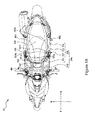
- Figure 2 is an exploded perspective view of a back shell portion 320 as shown in Figure 1A .
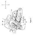
- Figure 3 is a side view of a part of Figure 1A .
- Figure 4A is a front view of a front side cover portion 322, a bearing cover portion 323, and a foot rest lever 500 in Figure 1A , with the foot rest lever 500 being in a received state.
- Figure 4B is a front view similar to Figure 4A , but with the foot rest lever 500 being in an expanded state.
- front, back, left, right, up, and down directions refer to the front, back, left, right, up, and down directions viewed by a rider riding on the straddle-type vehicle 10.
- the symbol U represents the up direction
- the symbol D represents the down direction
- the symbol F represents the front direction
- the symbol B represents the back direction.
- the symbol R represents the right direction
- the symbol L represents the left direction.
- the straddle-type vehicle 10 in this embodiment comprises a body frame 100, a steering shaft 110, a front fork 120, a front wheel 130, a power unit 200 (shown by a dotted line in Figure 3 ), a seat cushion 400, a foot rest lever 500, a back wheel 140, and a vehicle shell 300.
- a body frame 100 is formed by a pipe made of iron or other metal.
- the body frame 100 is provided with a head pipe portion 101, a lower frame portion 102 (shown by a dotted line in Figure 1A ), a bottom frame portion 103 (shown by a dotted line in Figure 1A ), and a back frame portion 104 (shown by a dotted line in Figure 1A ).
- the body frame 100 can be formed integrally through a bending process or can be integrated by welding a plurality of parts.
- the head pipe portion 101 is located in the center of the straddle-type vehicle in a width direction of the vehicle.
- the steering shaft 110 is rotatably inserted into the head pipe portion 101.
- An upper portion of the steering shaft 110 is connected with a handle portion 150.
- a lower portion of the steering shaft 110 is connected with a front fork 120.
- the front wheel 130 is rotatably supported by the front fork 120.
- the lower frame portion 102 is connected to the head pipe portion 101.
- the lower frame portion 102 extends downward from the head pipe portion 101.
- the bottom frame portion 103 is connected to a lower end portion of the lower frame portion 102.
- the bottom frame portion 103 extends backward from the lower frame portion 102.
- the back frame portion 104 is connected to a back end portion of the bottom frame portion 103.
- the back frame portion 104 obliquely extends backward and upward from the back end portion of the bottom frame portion 103.
- the seat cushion 400 is supported on the body frame 100.
- the seat cushion 400 is arranged above, e.g. directly above or overhead of, the back frame portion 104.
- the seat cushion 400 is located further backward than the head pipe portion 101.
- the seat cushion 400 is supported on the back frame portion 104 via a receiving portion (not shown).
- the seat cushion 400 may not be directly mounted on the body frame 100, but may be supported on the body frame 100 via another member, and, of course, may additionally or alternatively be directly mounted on the body frame 100.
- the seat cushion 400 includes a front edge portion 401, a left side edge portion 402, and a right side edge portion 403.
- the front edge portion 401 is located further forward than the left side edge portion 402 and the right side edge portion 403.
- the left side edge portion 402 obliquely extends leftward and backward from the front edge portion 401.
- the right side edge portion 403 obliquely extends rightward and backward from the front edge portion 401.
- the power unit 200 (shown by a dotted line in Figure 3 ) is arranged below, e.g. under or directly below, the seat cushion 400.
- the power unit 200 is supported on the body frame 100.
- the power unit 200 is swingably mounted on the body frame 100 via a stand.
- the power unit 200 has an output shaft (not shown).
- the back wheel 140 is rotatably supported by the output shaft.
- the power unit 200 and the back wheel 140 are formed in a unit swing manner in which they are swingable together relative to the body frame 100.
- the power unit 200 includes an engine as a driving source.
- the power unit 200 of the present invention can have a motor as the driving source instead of an engine, as long as it can be freely swingably supported on the body frame.
- the driving source is not specifically limited.
- the foot rest lever 500 is supported on the body frame 100 in such a manner that the foot rest lever 500 is rotatable about a pivot 510. Furthermore, the foot rest lever 500 may not be directly mounted on the body frame 100, but may be supported on the body frame 100 via another member, and, of course, may additionally or alternatively be directly mounted on the body frame 100, so long as the foot rest lever 500 is rotatable about the pivot 510.
- the foot rest lever 500 is supported on the body frame 100 in such a manner that the foot rest lever 500 is switchable between the received state (shown in Figure 4A ) and the expanded state (shown in Figure 4B ). The foot rest lever 500 rotates about the pivot 510 so that the foot rest lever 500 is switchable between the received state and the expanded state.
- the so-called received state is a state in which the foot rest lever 500 is not used or usable.
- the so-called expanded state is a state in which the foot rest lever 500 can be used.
- the foot rest lever 500 has a foot carrying face 500a and a pivotal connection portion 520.
- the foot carrying face 500a in the expanded state is a face for a co-rider riding on the seat cushion 400 to place their feet on.
- the pivotal connection portion 520 has an opening for the pivot 510 to pass through.
- the pivot 510 is supported by the pivotal connection portion 520.
- the foot rest lever 500 in the received state is arranged such that at least part or all of the foot carrying face 500a is located further upward than, e.g. higher, than the pivot 510.
- the foot rest lever 500 is configured to be within the width of the vehicle shell 300 in the left-right direction. That is, in the received state, the foot rest lever 500 is entirely arranged above, e.g. directly above or overhead of, a bearing face 323a of the bearing cover portion 323 of the vehicle shell 300.
- the foot carrying face 500a of the foot rest lever 500 is arranged outside the vehicle shell 300 in the left-right direction. That is, when changing from the received state to the expanded state, the foot rest lever 500 rotates about the pivot 510 orthogonal to the bearing face 323a of the bearing cover portion 323 of the vehicle shell 300, so that the foot carrying face 500a extends outward in the width direction of the vehicle shell 300 in the left-right direction. Therefore, the foot carrying face 500a of the foot rest lever 500 departs from a position above the bearing face 323a of the bearing cover portion 323 of the vehicle shell 300 and is moved to a position suitable for supporting the feet of the co-rider.
- the vehicle shell 300 includes a front shell portion 330, a back shell portion 320, and a bottom shell portion 340.
- the front shell portion 330 mainly covers the periphery of the head pipe portion 101 and the lower frame portion 102.
- the back shell portion 320 is located below, e.g. underneath or directly below, the seat cushion 400.
- the back shell portion 320 covers the front and two sides of the back frame portion 104.
- the back shell portion 320 is described in detail.
- the bottom shell portion 340 is located between the front shell portion 330 and the back shell portion 320 in the front-back direction.
- the bottom shell portion 340 connects the front shell portion 330 and the back shell portion 320.
- the bottom shell portion 340 includes a foot pedal, surface or board 310.
- the foot pedal or board 310 is located between the front wheel 130 and the seat cushion 400 in the front-back direction.
- the foot pedal or board 310 is arranged further forward and downward or lower than the seat cushion 400.
- the foot pedal or board 310 is arranged before or forwardly of the power unit 200.
- the foot pedal or board 310 is a face for carrying feet of a rider riding on the seat cushion 400 during travel.
- the foot pedal or board 310 is located above, e.g. directly above or overhead of, the bottom frame portion 103.
- the foot pedal or board 310 is located between the lower frame portion 102 and the back frame portion 104 in the front-back direction of the vehicle 10.
- the foot pedal or board 310 is flatly formed across the width direction of the vehicle.
- the so-called "flat foot pedal or board 310” means that any part of a foot carrying portion for the rider has a flatness such that the feet can be carried. That is, a concave-convex structure, for example, for slip resistance may also be formed on the foot pedal or board 310.
- the foot pedal or board 310 is not limited to the flat structure, as long as the foot pedal or board 310 enables the rider to place the feet thereon.
- a center of the foot pedal or board 310 in the left-right direction may also be located further upward than sides of the foot pedal or board 310 in the left-right direction.
- the back shell portion 320 when the straddle-type vehicle 10 is viewed from the side, the back shell portion 320 is located below, e.g. directly below or underneath, the seat cushion 400 in a manner of dividing the space below the seat cushion 400. Also, the back shell portion 320 includes a central cover portion 321, a front side cover portion 322, a bearing cover portion 323, and a back side cover portion 324. As shown in Figure 1 B , the central cover portion 321 is connected to a back edge of the foot pedal or board 310 (the connection position is shown by a dotted line in Figure 1B ).
- a front edge 321 a of the central cover portion 321 is a curve between a right end 321 d and a left end 321 e of the front edge 321 a of the central cover portion 321.
- the back edge of the foot pedal or board 310 is connected to the front edge 321 a of the central cover portion 321.
- the central cover portion 321 is connected to a back edge of the foot pedal or board 310 not only on outer sides (located at left and right ends of the front edge 321 a of the central cover portion 321), but also on a back edge on an inner side that is located further inward than the outer sides of the foot pedal or board 310 (located in a center of the front edge 321 a of the central cover portion 321).
- the central cover portion 321 has the front edge 321 a, a left lower side edge 321 b, a left upper side edge 321 c, a right lower side edge (not shown), and a right upper side edge (not shown). Also, the left lower side edge 321 b and the left upper side edge 321 c of the central cover portion 321 are symmetrical with the right lower side edge and the right upper side edge of the central cover portion 321 in the left and right direction. As described in detail, the central cover portion 321 is connected to the front side cover portions 322 at the left and right sides by the left lower side edge 321 b, the left upper side edge 321 c, the right lower side edge, and the right upper side edge.
- the left lower side edge 321 b obliquely extends backward and upward similarly to a side edge 323b of the bearing cover portion 323, and the left upper side edge 321c obliquely extends backward and downward similarly to a front edge 322c of an upper portion 322a of the front side cover portion 322.
- the right lower side edge and the right upper side edge are symmetrical with the left lower side edge 321 b and left upper side edge 321 c in the left and right direction, and thus their description is omitted.
- the center of the front edge 321a of the central cover portion 321 is located further forward than the right and left ends 321 d and 321e of the front edge 321 a of the central cover portion 321 in the front-back direction F-B of the straddle-type vehicle 10. That is, the front edge 321 a of the central cover portion 321 extends backward in the front-back direction F-B of the straddle-type vehicle 10 and extends towards two sides from the center in the left-right direction L-R of the straddle-type vehicle 10.
- the front side cover portion 322 is located behind or further rearward of the central cover portion 321 in the front-back direction F-B of the straddle-type vehicle 10.
- the front side cover portion 322 extends from a lower end of the seat cushion 400 until further downward than an upper end portion 200a of the power unit 200 and until further downward than a surface of the foot pedal or board 310, in the up-down direction U-D of the straddle-type vehicle 10.
- the surface of the foot pedal 310 is a face for the rider riding on the seat cushion 400 to place the feet on.
- two front side cover portions 322 each are connected behind the central cover portion 321.
- two back side cover portions 324 each are respectively connected behind the respective front side cover portions 322.
- a left side of the straddle-type vehicle 10 is taken as an example.
- the left lower side edge 321 b and the left upper side edge 321 c of the central cover portion 321 are connected to the side edge 323b of the bearing cover portion 323 and the front edge 322c of the upper portion 322a of the front side cover portion 322, respectively.
- a back edge 322g of the upper portion 322a of the front side cover portion 322 is connected to a front edge 324b of the back side cover portion 324.
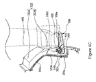
- Figure 4C is a front view in which the foot rest lever is in the expanded state and feet of a co-rider rest on the foot rest lever.
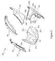
- Figure 5 is a side view of the front side cover portion 322 and the bearing cover portion 323 in Figure 1A .
- Figure 6 is a top view of the front side cover portion 322, the bearing cover portion 323, and the foot rest lever 500 in Figure 1A .
- Figure 7 is a side view of a part of Figure 1A , in which feet of the co-rider rest on the foot rest lever 500.
- the front side cover portion 322 in this embodiment includes the upper portion 322a and a lower portion 322b.
- a front end portion 322a1 of the upper portion 322a of the front side cover portion 322 is located further forward than a back end portion 322b1 of the lower portion 322b of the front side cover portion 322 in the front-back direction F-B of the straddle-type vehicle 10.
- the upper portion 322a is located further inward than the lower portion 322b in the left-right direction L-R of the straddle-type vehicle 10.
- the front side cover portion 322 in this embodiment is boomerang-shaped, arrow head shaped, or v-shaped.
- the front side cover portion 322 in this embodiment is formed by the upper portion 322a of the front side cover portion 322 obliquely extending backward and downward and the lower portion 322b of the front side cover portion 322 obliquely extending forward and downward, wherein the upper portion 322a and the lower portion 322b are consecutive to one another.
- the shape of the front side cover portion 322 of the present invention is not limited to the foregoing shape.
- an angle between the side edge 323b of the bearing cover portion 323 and the front edge 322c of the upper portion 322a of the front side cover portion 322 may also be any angle up to 180 degrees.
- an angle between a front edge 322d of the lower portion 322b of the front side cover portion 322 and the front edge 322c of the upper portion 322a of the front side cover portion 322 may also be any angle up to 180 degrees.
- an angle between the side edge 323b of the bearing cover portion 323 (the front edge 322d of the lower portion 322b of the front side cover portion 322) and the front edge 322c of the upper portion 322a of the front side cover portion 322 may also be smaller than the angle shown in Figure 5 . That is, any variations in shape of the front side cover portion 322 is allowed, as long as the front or frontmost end portion 322a1 of the upper portion 322a is located further forward than the back or backmost end portion 322b1 of the lower portion 322b in the front-back direction F-B of the straddle-type vehicle 10.
- the bearing cover portion 323 is connected between the left lower side edge 321 b of the central cover portion 321 and the front edge 322d (shown by a dotted line in Figure 2 ) of the lower portion 322b by extending in the left-right direction L-R of the straddle-type vehicle 10, and has the bearing face 323a for bearing the foot rest lever 500 and facing the up direction of the straddle-type vehicle 10.
- an imaginary extension line A extending from the bearing face 323a of the bearing cover portion 323 passes through the seat cushion 400.
- the imaginary extension line A is a slope of a plane, that is, the bearing face 323a, formed by the side edge 323b of the bearing cover portion 323 and the front edge 322d of the lower portion 322b. That is, the imaginary extension line A obliquely extends backward to pass through the seat cushion 400 in such a manner that the foot rest lever 500 carried by the bearing face 323a can move to a position suitable for supporting the foot of the co-rider.
- the imaginary extension line A can be appropriately set in a range from an imaginary extension line A' passing through the backmost end of the seat cushion 400 to an imaginary extension line A", which is optimally substantially vertical.
- a lower edge (see Figure 3 ) of the back side cover portion 324 is located further upward than, e.g. higher than or above, the power unit 200 in the up-down direction U-D of the straddle-type vehicle 10 and extends backward from the back edge 322g of the upper portion 322a in the front-back direction F-B of the straddle-type vehicle 10.
- the bearing face 323a is not limited to a plane.
- the bearing face 323a may also be a curved surface or a concave-convex surface.
- the imaginary extension line A can be appropriately defined.
- the imaginary extension line A may be a slope between the frontmost end and the backmost end of the bearing face 323a, may also be a slope along an outer edge of the bearing face 323a, and may also be a slope between the pivot 510 of the foot rest lever 500 located above the bearing face 323a and the backmost end of the bearing face 323a.
- the width of the lower portion 322b of the front side cover portion 322 in the front-back direction F-B of the straddle-type vehicle 10 increases from the lower end to the upper end.
- the present invention is not limited to the width of the lower portion 322b of the front side cover portion 322 in the front-back direction F-B of the straddle-type vehicle 10 increasing from the lower end to the upper end, as long as the lower portion 322b of the front side cover portion 322 has an area against which inner sides of heels 602 of the feet can abut.
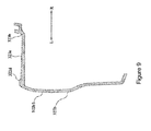
- a surface of the lower portion 322b of the front side cover portion 322 is of a concave-convex shape.
- a front portion of the lower portion 322b of the front side cover portion 322 is provided with a protrusion 322b3 obliquely extending forward and downward.
- a center of the protrusion 322b3 of the front side cover portion 322 is located further outward than a front portion and a back portion of the protrusion 322b3.
- Figure 9 is a schematic cross-sectional view taken along a line 9-9' in Figure 5 .
- the surface of the lower portion 322b of the front side cover portion 322 is not limited to the concave-convex shape, as long as the surface of the lower portion 322b of the front side cover portion 322 is capable of supporting the feet on the foot rest lever 500.
- the so-called “surface” refers to a face exposed outside the straddle-type vehicle 10 and refers to a face capable of being seen when the straddle-type vehicle 10 is viewed from the side, front and from above.
- the front edge 322c of the upper portion 322a of the front side cover portion 322 extends substantially obliquely backward and downward from the seat cushion 400 in the up-down direction U-D of the straddle-type vehicle 10 and the front-back direction F-B of the straddle-type vehicle 10; and the front edge 322d of the lower portion 322b of the front side cover portion 322 extends substantially obliquely forward and downward from the upper portion 322a of the front side cover portion 322 in the up-down direction U-D of the straddle-type vehicle 10 and the front-back direction F-B of the straddle-type vehicle 10 and is connected to the back edge of the foot pedal or board 310.
- the present invention is not limited to a configuration in which, when the straddle-type vehicle 10 is viewed from the side, the front edge 322c of the upper portion 322a of the front side cover portion 322 extends substantially obliquely backward and downward from the seat cushion 400 in the up-down direction U-D of the straddle-type vehicle 10 and the front-back direction F-B of the straddle-type vehicle 10 and the front edge 322d of the lower portion 322b of the front side cover portion 322 extends substantially obliquely forward and downward from the upper portion 322a of the front side cover portion 322 in the up-down direction U-D of the straddle-type vehicle 10 and the front-back direction F-B of the straddle-type vehicle 10 and is connected to the back edge of the foot pedal or board 310, as long as the front end portion 322a1 of the upper portion 322a is located further forward than the back end portion 322b1 of the lower portion 322b in the front-back direction F-B of the
- the front end portion 322a1 of the upper portion 322a of the front side cover portion 322 is located further inward than the back end portion (which in this embodiment is the same position as the back end portion 322b1 of the lower portion 322b) of the upper portion 322a of the front side cover portion 322 in the left-right direction L-R of the straddle-type vehicle 10, and the front end portion 322a1 of the upper portion 322a of the front side cover portion 322 is located further inward than the front edge 322d of the lower portion 322b of the front side cover portion 322 in the left-right direction L-R of the straddle-type vehicle 10.
- the present invention is not limited to a configuration in which, when the straddle-type vehicle 10 is viewed from above, the front end portion 322a1 of the upper portion 322a of the front side cover portion 322 is located further inward than the back end portion of the upper portion 322a of the front side cover portion 322 in the left-right direction L-R of the straddle-type vehicle 10, and the front end portion 322a1 of the upper portion 322a of the front side cover portion 322 is located further inward than the front edge 322d of the lower portion 322b of the front side cover portion 322 in the left-right direction L-R of the straddle-type vehicle 10, as long as when the straddle-type vehicle 10 is viewed from above, the upper portion 322a is located further inward than the lower portion 322b in the left-right direction L-R of the straddle-type vehicle 10.
- the bearing cover portion 323 is located further outward than an outer edge portion 322e (shown by a dotted line at the upper part in Figure 6 ) of the front portion of the upper portion 322a of the front side cover portion 322 in the left-right direction L-R of the straddle-type vehicle 10.
- the outer edge portion 322e of the front portion of the upper portion 322a of the front side cover portion 322 is a line segment from the front end portion 322a1 of the upper portion 322a of the front side cover portion 322 to a back end portion 322a2 (when the straddle-type vehicle 10 is viewed from above, an intersection point of the upper portion 322 and the bearing cover portion 323) of the front portion of the upper portion 322a of the front side cover portion 322.
- the foot rest lever 500 is located further outward than the upper portion 322a of the front side cover portion 322 in the left-right direction L-R of the straddle-type vehicle 10.
- the foot rest lever 500 has the pivotal connection portion 520.
- the pivotal connection portion 520 is disposed on the bearing face 323a.
- the pivotal connection portion 520 is located further inward than an outer edge portion 322f (shown by a dotted line at the lower part in Figure 6 ) of the lower portion 322b of the front side cover portion 322 in the left-right direction L-R of the straddle-type vehicle 10.
- the outer edge portion 322f of the lower portion 322b of the front side cover portion 322 is a line segment from a front end portion 322b2 of the lower portion 322b of the front side cover portion 322 to the back end portion 322b1 of the lower portion 322b of the front side cover portion 322.
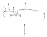
- FIG. 8 a schematic cross-sectional view taken along a line 8-8' in Figure 3 is shown.
- the back edge 322g of the upper portion 322a of the front side cover portion 322 is connected to the front edge 324b of the back side cover portion 324 to form a segment difference, such as a border, boundary, or section delineator, which may be a step between the back edge 322g and the front edge 324b, and when the straddle-type vehicle 10 is viewed from above, the upper portion 322a of the front side cover portion 322 is located further outward than the back side cover portion 324 in the left-right direction L-R of the straddle-type vehicle 10.
- a segment difference such as a border, boundary, or section delineator
- the present invention is not limited to a configuration in which the back edge 322g of the upper portion 322a of the front side cover portion 322 is connected to the front edge 324b of the back side cover portion 324 to form a segment difference, and when the straddle-type vehicle 10 is viewed from above, the upper portion 322a of the front side cover portion 322 is located further outward than the back side cover portion 324 in the left-right direction L-R of the straddle-type vehicle 10, as long as the co-rider can use the inner sides of the heels of the feet to clamp an upper part of the lower portion 322b of the front side cover portion 322 to improve stability.
- the height h of the foot rest lever 500 in the up-down direction U-D of the straddle-type vehicle 10 is greater than the length l of the foot rest lever 500 in the front-back direction F-B of the straddle-type vehicle 10.
- the height h is a length between a horizontal line passing through an upper end of the foot rest lever 500 and a horizontal line passing through a lower end thereof when the straddle-type vehicle 10 is viewed from the side.
- the length l is a length between a perpendicular or vertical line passing through a front end of the foot rest lever 500 and a perpendicular or vertical line passing through a back end thereof when the straddle-type vehicle 10 is viewed from the side.
- the height h of the foot rest lever 500 in the up-down direction U-D of the straddle-type vehicle 10 need not be greater than the length l of the foot rest lever 500 in the front-back direction F-B of the straddle-type vehicle 10, so long as the co-rider can apply force when switching the foot rest lever 500 to the expanded state.
- the foot rest lever 500 when the foot rest lever 500 is in the received state, at least part or all of the foot rest lever 500 is located above, e.g. directly above or overhead of, the bearing face 323a and is substantially parallel to the bearing face 323a.
- a straddle-type vehicle 10 in one embodiment of the present invention comprises a body frame 100, a power unit 200, a seat cushion 400, a foot rest lever 500, and a vehicle shell 300.
- the power unit 200 is freely swingably supported on the body frame 100.
- the seat cushion 400 is located higher than the power unit 200.
- the foot rest lever 500 is supported on the body frame 100 in such a manner that the foot rest lever 500 is rotatable about a pivot 510.
- the foot rest lever 500 has a foot carrying face 500a switchable between a received state and an expanded state.
- the vehicle shell 300 covers the body frame 100 and includes a foot pedal or board 310 and a back shell portion 320.
- the foot pedal or board 310 is located before, e.g. forwardly of, and below, e.g. lower than, the seat cushion 400 and before, e.g. forwardly of, the power unit 200.
- the back shell portion 320 is connected to a back edge of the foot pedal or board 310.
- the back shell portion 320 When the straddle-type vehicle 10 is viewed from the side, the back shell portion 320 is located below, e.g. directly below or underneath, the seat cushion 400 in a manner of dividing the space below the seat cushion 400.
- the back shell portion 320 includes a central cover portion 321, a front side cover portion 322, a bearing cover portion 323, and a back side cover portion 324.
- the central cover portion 321 is connected to the back edge of the foot pedal or board 310.
- a center of the front edge 321a of the central cover portion 321 is located further forward in the front-back direction of the straddle-type vehicle 10, while two ends of the front edge 321 a of the central cover portion 321 are located further backward in front-back direction of the straddle-type vehicle 10.
- the front side cover portion 322 is located behind the central cover portion 321 and extends from a lower end of the seat cushion 400 to a position further downward than an upper end portion 200a of the power unit 200 in the up-down direction of the straddle-type vehicle 10.
- a front end portion 322a1 of an upper portion 322a of the front side cover portion 322 is located further forward than a back end portion 322b1 of a lower portion 322b of the front side cover portion 322 in the front-back direction of the straddle-type vehicle 10.
- the upper portion 322a of the front side cover portion 322 is located further inward than the lower portion 322b of the front side cover portion 322 in the in the left-right direction of the straddle-type vehicle 10.
- the bearing cover portion 323 is connected between a lower side edge (a left lower side edge 321 b in an example of a left side of the straddle-type vehicle) of the central cover portion 321 and a front edge 322d of the lower portion 322b of the front side cover portion 322 by extending in the left-right direction of the straddle-type vehicle 10, and has a bearing face 323a for bearing the foot rest lever 500 and facing the up direction of the straddle-type vehicle 10.
- an imaginary extension line A extending from the bearing face 323a passes through the seat cushion 400.
- a lower edge of the back side cover portion 324 is located above, e.g. higher than or directly above or overhead of, the power unit 200 and extends backward from a back edge 322g of the upper portion 322a of the front side cover portion 322.
- the lower portion 322b of the front side cover portion 322 is located further outward than the upper portion 322a in the left-right direction L-R of the straddle-type vehicle 10 so that when the foot rests on the foot rest lever 500 in the expanded state, heels 602 of two feet (parts near shoes) of the co-rider easily clamp, from the outside, the lower portions 322b of the front side cover portions 322 located at two sides of the straddle-type vehicle 10, thereby ensuring the comfort of the shank 601 and the stability of the feet of the co-rider and increases the foot comfort.
- the foot rest lever 500 can be disposed on the bearing face 323a of the bearing cover portion 323 facing the up direction of the straddle-type vehicle 10 without being shielded by the back shell portion 320, so that a pivot 510 of the foot rest lever 500 is exposed towards the up direction of the straddle-type vehicle 10, thereby achieving good operability.
- the shape of the front side cover portion 322 of the present invention is not limited to the foregoing shape.
- an angle between a side edge 323b of the bearing cover portion 323 and a front edge 322c of the upper portion 322a of the front side cover portion 322 may be up to 180 degrees.
- an angle between a front edge 322d of the lower portion 322b of the front side cover portion 322 and the front edge 322c of the upper portion 322a of the front side cover portion 322 may also be up to 180 degrees.
- an angle between a side edge 323b of the bearing cover portion 323 (the front edge 322d of the lower portion 322b of the front side cover portion 322) and the front edge 322c of the upper portion 322a of the front side cover portion 322 may be smaller than the angle shown in Figure 5 . That is, any variation in shape of the front side cover portion 322 is allowed, as long as the front end portion 322a1 of the upper portion 322a is located further forward than the back end portion 322b1 of the lower portion 322b in the front-back direction F-B of the straddle-type vehicle 10.
- the bearing face 323a is not limited to a plane.
- the bearing face 323a may also be a curved surface or a concave-convex surface.
- the imaginary extension line A can be appropriately defined.
- the imaginary extension line A may be a slope between the frontmost end and the backmost end of the bearing face 323a, may also be a slope along an outer edge of the bearing face 323a, and/or may also be a slope between the pivot 510 of the foot rest lever 500 located above the bearing face 323a and the backmost end of the bearing face 323a.
- the width of the lower portion 322b of the front side cover portion 322 in the front-back direction F-B of the straddle-type vehicle 10 gets greater or increases from the lower end to the upper end.
- the present invention is not limited to arrangements in which the width of the lower portion 322b of the front side cover portion 322 in the front-back direction F-B of the straddle-type vehicle 10 gets greater or increases from the lower end to the upper end, as long as the lower portion 322b of the front side cover portion 322 has an area against which the inner sides of the heels 602 of the feet can abut.
- a surface of the lower portion 322b of the front side cover portion 322 is of a concave-convex shape.
- the concave-convex structure on the surface of the lower portion 322b of the front side cover portion 322 can improve the rigidity of the lower portion 322b.
- a convex portion of the concave-convex structure can strengthen the support towards the outside to support the feet on the foot rest lever 500, thereby further improving the stable feeling of the feet and improving the comfort.
- the surface of the lower portion 322b of the front side cover portion 322 is not limited to the concave-convex shape, as long as the surface of the lower portion 322b of the front side cover portion 322 can support the feet on the foot rest lever 500.
- the front edge 322c of the upper portion 322a of the front side cover portion 322 extends substantially obliquely backward and downward from the seat cushion 400 in the up-down direction of the straddle-type vehicle 10 and the front-back direction of the straddle-type vehicle 10; and the front edge 322d of the lower portion 322b of the front side cover portion 322 extends substantially obliquely forward and downward from the upper portion 322a of the front side cover portion 322 in the up-down direction of the straddle-type vehicle 10 and the front-back direction of the straddle-type vehicle 10 and is connected to the back edge of the foot pedal or board 310.
- a central part of the front side cover portion 322 in the up-down direction U-D of the straddle-type vehicle 10 has a shape of substantially a boomerang or an arrow head or '>' shape protruding or pointing backward of the straddle-type vehicle 10, thereby improving the rigidity of the front side cover portion 322, strengthening the support towards the outside to indeed support the feet on the foot rest lever 500, and thus further improving the stable feeling of the feet and improving the comfort.
- the present invention is not limited to configurations in which, when the straddle-type vehicle 10 is viewed from the side, the front edge 322c of the upper portion 322a of the front side cover portion 322 extends substantially obliquely backward and downward from the seat cushion 400 in the up-down direction U-D of the straddle-type vehicle 10 and the front-back direction F-B of the straddle-type vehicle 10, and the front edge 322d of the lower portion 322b of the front side cover portion 322 extends substantially obliquely forward and downward from the upper portion 322a of the front side cover portion 322 in the up-down direction U-D of the straddle-type vehicle 10 and the front-back direction F-B of the straddle-type vehicle 10 and is connected to the back edge of the foot pedal or board 310, as long as the front end portion 322a1 of the upper portion 322a is located further forward than the back end portion 322b1 of the lower portion 322b in the front-back direction F-B of the stra
- the front end portion 322a1 of the upper portion 322a of the front side cover portion 322 is located further inward than the back end portion 322b1 of the upper portion 322a of the front side cover portion 322 in the left-right direction of the straddle-type vehicle 10
- the front end portion 322a1 of the upper portion 322a of the front side cover portion 322 is located further inward than the front edge 322d of the lower portion 322b of the front side cover portion 322 in the left-right direction of the straddle-type vehicle 10.
- the front end portion 322a1 of the upper portion 322a of the front side cover portion 322 is located further inward than the back end portion in the left-right direction L-R of the straddle-type vehicle 10, so that the foot on the respective foot rest lever 500 is relatively close to the lower portion 322b of the front side cover portion 322, and thus heels 602 of two feet of the co-rider easily clamp, from the outside, the lower portions 322b of the front side cover portions 322 located at two sides of the straddle-type vehicle 10, so as to ensure the stable feeling of the feet.
- the front end portion 322a1 of the upper portion 322a of the front side cover portion 322 is located further inward than the front edge 322d of the lower portion 322b in the left-right direction L-R of the straddle-type vehicle 10, so that ankles 601 of the co-rider may not contact the upper portion 322a, thereby further improving the comfort of the feet of the co-rider.
- the present invention is not limited to a configuration in which, when the straddle-type vehicle 10 is viewed from above, the front end portion 322a1 of the upper portion 322a of the front side cover portion 322 is located further inward than the back end portion of the upper portion 322a of the front side cover portion 322 in the left-right direction L-R of the straddle-type vehicle 10, and the front end portion 322a1 of the upper portion 322a of the front side cover portion 322 is located further inward than the front edge 322d of the lower portion 322b of the front side cover portion 322 in the left-right direction L-R of the straddle-type vehicle 10, as long as when the straddle-type vehicle 10 is viewed from the above, the upper portion 322a is located further inward than the lower portion 322b in the left-right direction L-R of the straddle-type vehicle 10.
- the bearing cover portion 323 is located further outward than the outer edge portion 322e of the front portion of the upper portion 322a of the front side cover portion 322 in the left-right direction of the straddle-type vehicle 10.
- the foot rest lever 500 when the straddle-type vehicle 10 is viewed from above, the foot rest lever 500 is located further outward than the upper portion 322a of the front side cover portion 322 in the left-right direction of the straddle-type vehicle 10.
- the foot rest lever 500 when the straddle-type vehicle 10 is viewed from above, the foot rest lever 500 is disposed further outward than the upper portion 322a of the front side cover portion 322. Thus, when the straddle-type vehicle 10 is viewed from above, the foot rest lever 500 is exposed out of the back shell portion 320, thereby improving the operability of the foot rest lever 500.
- the foot rest lever 500 has a pivotal connection portion 520.
- the pivotal connection portion 520 is disposed on the bearing face 323a. When the straddle-type vehicle 10 is viewed from above, the pivotal connection portion 520 is located further inward than the outer edge portion 322f of the lower portion 322b of the front side cover portion 322 in the left-right direction of the straddle-type vehicle 10.
- the foot rest lever 500 in the expanded state extends towards the outside of the outer edge portion 322f of the lower portion 322b from the pivot 510 located in the inner side of the outer edge portion 322f of the lower portion 322b in the left-right direction L-R of the straddle-type vehicle 10, such that the foot on the foot rest lever 500 is relatively close to the lower portion 322b of the front side cover portion 322. Therefore, the heels 602 of two feet of the co-rider easily clamp, from the outside, the lower portions 322b of the front side cover portions 322 located at two sides of the straddle-type vehicle 10, so as to ensure stability for the feet.
- the back edge 322g of the upper portion 322a of the front side cover portion 322 is connected to the front edge 324b of the back side cover portion 324 to form a segment difference, such as a boundary, border, or section delineator, and when the straddle-type vehicle 10 is viewed from above, the upper portion 322a of the front side cover portion 322 is located further outward than the back side cover portion 324 in the left-right direction of the straddle-type vehicle 10.
- a segment difference is formed between the back edge 322g of the upper portion 322a of the front side cover portion 322 and the front edge 324b of the back side cover portion 324 and the front side cover portion 322 protrudes towards the outside, so that the foot on the foot rest lever 500 is relatively close to the front side cover portion 322. Therefore, the heels of two feet of the co-rider easily clamp, from the outside, the lower portions 322b of the front side cover portions 322 located at two sides of the straddle-type vehicle 10, so as to further ensure stability for the feet.
- the back edge 322g of the upper portion 322a of the front side cover portion 322 is connected to the front edge 324b of the back side cover portion 324 to form a segment difference and when the straddle-type vehicle 10 is viewed from above, the upper portion 322a of the front side cover portion 322 is located further outward than the back side cover portion 324 in the left-right direction L-R of the straddle-type vehicle 10, as long as the co-rider can use the inner sides of the heels 602 of the feet to clamp an upper part of the lower portion 322b of the front side cover portion 322 to improve stability.
- a straddle-type vehicle 10 in one embodiment of the present invention in the case that the foot rest lever 500 is in the received state, when the straddle-type vehicle 10 is viewed from the side, the height h of the foot rest lever 500 in the up-down direction of the straddle-type vehicle 10 is greater than the length l of the foot rest lever 500 in the front-back direction of the straddle-type vehicle 10.
- the foot rest lever 500 in the received state is very obliquely arranged, so that the co-rider easily applies a force when switching the foot rest lever 500 to the expanded state and thus the operability of the foot rest lever 500 is improved.
- the foot rest lever 500 in the case that the foot rest lever 500 is in the received state, when the straddle-type vehicle 10 is viewed from the side, it is not essential that the height h of the foot rest lever 500 in the up-down direction U-D of the straddle-type vehicle 10 is greater than the length l of the foot rest lever 500 in the front-back direction F-B of the straddle-type vehicle 10, as long as the co-rider can apply a force when switching the foot rest lever 500 to the expanded state.
- the foot rest lever 500 when the foot rest lever 500 is in the received state, at least part or all of the foot rest lever 500 is located above, e.g.
- the foot rest lever 500 is very obliquely arranged, and thus the bearing face 323a parallel to the foot rest lever 500 also has a steep angle, so that the front edge 322d of the lower portion 322b of the front side cover portion 322 parallel to the bearing face 323a is also of a steep shape and thus the feet on the foot rest lever 500 are relatively close to the lower portion 322b of the front side cover portion 322. Therefore, the co-rider easily applies a force when switching the foot rest lever 500 to the expanded state so that the operability of the foot rest lever 500 is improved.
- the present invention is intended to provide a straddle-type vehicle, wherein the back shell portion of the straddle-type vehicle can take account of both the operability of the foot rest lever and the foot bearing comfort.
- the good operability can be achieved by disposing the foot rest lever on the bearing face of the bearing cover portion facing the up direction of the straddle-type vehicle without being shielded by the back shell portion, so that the pivot of the foot rest lever is exposed towards the up direction of the straddle-type vehicle.
- the upper portion of the front side cover portion is located further inward than the lower portion in the left-right direction of the straddle-type vehicle without affecting shanks of the co-rider
- the lower portion of the front side cover portion is located further outward than the upper portion in the left-right direction of the straddle-type vehicle so that when feet of the co-rider rest on the foot rest levers in the expanded state, heels of two feet (parts near shoes) of the co-rider easily clamp, from the outside, the lower portions of the front side cover portions located at two sides of the straddle-type vehicle, thereby ensuring the comfort of the shanks and the stability of the feet of the co-rider and thus achieving good foot bearing comfort.
- straddle-type vehicle or motor vehicle used herein, and as used in the art, is meant to include the following terms also used in the art: saddle-ride type vehicle or motor vehicle, saddle-straddling type vehicle or motor vehicle, and includes: motorcycles and motorbikes as well as motor tricycles and All Terrain Vehicles (ATVs), scooters, mopeds and snowmobiles.
- ATVs All Terrain Vehicles
Abstract
Description
- The present invention relates to a straddle-type vehicle or saddle-ride vehicle, and in particular, to a scooter-type straddle-type vehicle.
- This application is based on, and claims priority to Chinese Patent Application No.
201410575178.9, filed on October 24, 2014 - In the past, a straddle-type vehicle such as a scooter-type vehicle, has typically utilized a tandem foot rest of a co-rider disposed at a position corresponding to a riding posture of the co-rider according to the size of the vehicle, and specifically, to the height of a seat cushion.
- In Taiwan Patent Publication No.
1421190 1421190 - In Taiwan Patent Publication No.
1400172 Figure 1 in Taiwan Patent Publication No.1400172 right side cover 9. A receiving hole (not shown) is disposed in the left andright side cover 9 at a position corresponding to a folding foot rest lever mechanism 30, thereby receiving the folding foot rest lever mechanism 30 in the received state in the receiving hole, so that the vehicle body of the scooter-type vehicle 1 appears to be flush. A foot pedal 5 is connected to the left andright side cover 9 at two sides and located before the folding foot rest lever mechanism 30. Therefore, it can be known that a pivot of the folding foot rest lever mechanism 30 is located inside the receiving hole of the left andright side cover 9, either in an expanded state or in a received state. - In Taiwan Patent Publication No.
1421190 - Also, in Taiwan Patent Publication No.
1400172 right side cover 9, when feet of a co-rider rest on the folding foot rest lever mechanism 30, the feet of the co-rider may be in a position close to the left andright side cover 9, so that the feet may be easily located closely against the left andright side cover 9 near the feet. That is, the feet may have good bearing comfort. However, the folding foot rest lever mechanism 30 may be fixed in the receiving hole without exposure of the pivot, so the whole body may be embedded in the receiving hole in the received state. Therefore, it may be difficult to expand the folding foot rest lever mechanism 30 from the received state where the whole body is embedded in the receiving hole. That is, the operability may be poor. - It is an object of at least one embodiment of at least one aspect of the present invention to obviate or at least mitigate one or more problems or disadvantages in the prior art.
- Various aspects of the present invention may be defined in the independent claims. Some preferred features may be defined in the dependent claims.
- A vehicle, such as a straddle-type vehicle, of the present invention may comprise a body frame, a power unit, a seat, a seat cushion, a foot rest lever or member, and/or a vehicle shell. The power unit may be freely and swingably supported upon the body frame. The seat and/or seat cushion may be located higher than the power unit. The foot rest lever or member may be supported on the body frame. The foot rest lever or member may be rotatable about a pivot. The foot rest lever or member may have a foot carrying face, which may be moveable or switchable between a received state and an extended or expanded state. The vehicle shell may cover the body frame. The vehicle shell may include a foot pedal, surface or board and may include a back shell portion. At least part or all of the foot pedal, surface or board may be located forwardly of, in front of, or before and below, lower than or underneath the seat and/or seat cushion. The foot pedal, surface or board may be located before, forward or in front of the power unit. The back shell portion may be connected to a back edge of the foot pedal, surface or board.
- When the vehicle is viewed sideways or from the side, the back shell portion of the vehicle may be located below, lower than, directly under or beneath the seat and/or seat cushion, e.g. in a manner of dividing the space below the seat and/or seat cushion. The back shell portion may include one or more or each of: a central cover portion, a front side cover portion, a bearing cover portion, and a back side cover portion. The central cover portion may be connected to the back edge of the foot pedal, surface or board. When the vehicle is viewed downward or from above, a center of a front edge of the central cover portion may be located further forward in the front-back direction of the vehicle, than two ends of the front edge of the central cover portion, which may be located further backward in front-back direction of the vehicle. When the vehicle is viewed sideways or from the side, the front side cover portion may be located behind or rearwardly of the central cover portion and may extend from a lower or lowermost end of the seat and/or seat cushion until further downward than an upper or uppermost end portion of the power unit in the up-down direction of the vehicle. A front end portion of an upper or uppermost portion of the front side cover portion may be located further forward than a back or rearmost end portion of a lower or lowermost portion of the front side cover portion in the front-back direction of the vehicle. When the vehicle is viewed downward or from above, the upper or uppermost portion of the front side cover portion may be located further inward than the lower or lowermost portion of the front side cover portion in the in the left-right direction of the vehicle. When the vehicle is viewed downward or from above, the bearing cover portion may be connected between a lower or lowermost side edge (a left lower side edge in an example of a left side of the vehicle) of the central cover portion and a front or frontmost edge of the lower or lowermost portion of the front side cover portion, e.g. by extending in the left-right direction of the vehicle, and may have a bearing face for bearing the foot rest lever. The bearing face may face, or at least partially or obliquely face, the up direction of the vehicle. When the vehicle is viewed sideways or from the side, an imaginary extension line extending along and/or from the bearing face may pass through the seat and/or seat cushion. When the vehicle is viewed sideways or from the side, a lower or lowermost edge of the back side cover portion may be located above, higher than, directly above or overhead of the power unit and may extend backward from a back or rearmost edge of the upper or uppermost portion of the front side cover portion.
- In the vehicle of the present invention, preferably, when the vehicle is viewed sideways or in a side view, the width of the lower or lowermost portion of the front side cover portion in the front-back direction of the vehicle may get greater or increase from a lower or lowermost end to an upper or uppermost end.
- In the vehicle of the present invention, preferably, a surface of the lower or lowermost portion of the front side cover portion may be of a concave-convex shape. The concave-convex shape may comprise at least one protrusion, which may extend obliquely forward and/or downward. A center of the at least one protrusion may be located further outward than a front portion and/or a back portion of the protrusion. A part of the at least one protrusion proximate, adjacent, toward, or close to the front edge of the lower portion of the front side cover portion may protrude outside in the left-right direction of the vehicle. The at least one protrusion may be disposed at the front portion of the lower portion of the front side cover portion.
- In the vehicle of the present invention, preferably, when the vehicle is viewed sideways or in a side view, a front or frontmost edge of the upper or uppermost portion of the front side cover portion may substantially extend obliquely backward and downward (that is, toward the down-and-back direction) from the seat and/or seat cushion in the up-down direction of the vehicle and the front-back direction of the vehicle. The front edge of the lower or lowermost portion of the front side cover portion may substantially extend obliquely forward and downward (that is, toward the down-and-front direction) from the upper or uppermost portion of the front side cover portion in the up-down direction of the vehicle and the front-back direction of the vehicle and may be connected to the back edge of the foot pedal, surface or board.
- In the vehicle of the present invention, preferably, when the vehicle is viewed downward or from above or in a plan view, a front or frontmost end portion of the upper or uppermost portion of the front side cover portion may be located further inward in the left-right direction of the vehicle than a back or rear or rearmost end portion of the upper or uppermost portion of the front side cover portion, and the front or frontmost end portion of the upper or uppermost portion of the front side cover portion may be located further inward in the left-right direction of the vehicle than the front or frontmost edge of the lower or lowermost portion of the front side cover portion.
- In the vehicle of the present invention, preferably, when the vehicle is viewed downward or from above or in a plan view, the bearing cover portion may be located further outward in the left-right direction of the vehicle than an outer edge portion of a front or frontmost portion of the upper or uppermost portion of the front side cover portion.
- In the vehicle of the present invention, preferably, when the vehicle is viewed downward, from above or in a plan view, the foot rest lever or member may be located further outward in the left-right direction of the vehicle than the upper or uppermost portion of the front side cover portion.
- In the vehicle of the present invention, preferably, the foot rest lever or member may have a pivotal connection portion. The pivotal connection portion may be disposed on the bearing face. When the vehicle is viewed downward or from above or in a plan view, the pivotal connection portion may be located further inward in the left right direction of the straddle-type vehicle than an outer edge portion of the lower or lowermost portion of the front side cover portion.
- In the vehicle of the present invention, preferably, the back edge of the upper or uppermost portion of the front side cover portion may be connected to a front edge of the back side cover portion to form a segment difference, such as a boundary, border or section delineator. When the vehicle viewed downward or from above or in a plan view, the upper or uppermost portion of the front side cover portion may be located further outward in the left-right direction of the vehicle than the back side cover portion. The segment difference may be or comprise a step.
- In the vehicle of the present invention, preferably, in the case that the foot rest lever or member is in the received state, when the vehicle is viewed sideways or from the side, the height of the foot rest lever in the up-down direction of the vehicle may be greater than the length of the foot rest lever in the front-back direction of the vehicle.
- In the vehicle of the present invention, preferably, when the foot rest lever or member is in the received state, the foot rest lever or member may be located above, e.g. directly above or over, the bearing face and/or may be substantially parallel to the bearing face. The bearing face may be inclined, e.g. so as to be lower at a front end and higher at a rear end thereof, e.g. when viewed in a vehicle side view.
- The present invention is made in view of the foregoing problems, and is intended to provide a vehicle, such as a saddle-ride or straddle-type vehicle, wherein the back shell portion of the vehicle can take account of both the operability of the foot rest lever and the foot bearing comfort.
- According to a second aspect of the invention is a vehicle shell for a vehicle, such as a straddle-type vehicle. The vehicle may comprise a body frame, a power unit freely swingably supported on the body frame, a seat and/or seat cushion located higher than the power unit, and a foot rest lever being rotatably supported on the body frame using a pivot and the foot rest lever or member having a foot carrying face moveable or switchable between a received state and an extended or expanded state.
- The vehicle shell may be configured to cover the body frame. The vehicle shell may comprise a foot pedal, surface or board. The vehicle shell may comprise a back shell portion.
- The foot pedal, surface or board may be locatable forward of and below, lower than, directly below or underneath the seat and/or seat cushion. The foot pedal, surface or board may be locatable forward of the power unit.
- The back shell portion may be connected or connectable to a back edge of the foot pedal, surface or board, such that, when the vehicle is viewed from the side, the back shell portion may be located below, lower than, directly below or underneath the seat and/or seat cushion, e.g. so as to divide a space below the seat and/or seat cushion.
- The back shell portion may comprise a central cover portion, which may be connected or connectable to the back edge of the foot pedal, surface or board such that, when the vehicle is viewed from above, a center of a front edge of the central cover portion may be located further forward in the front-back direction of the vehicle than two ends of the front edge of the central cover portion.
- The back shell portion may comprise a front side cover portion, which may be arranged or arrangeable such that, when the vehicle is viewed from the side, the front side cover portion is located further rearward in the front-back direction than the central cover portion and may extend from a lower end of the seat and/or seat cushion in the up-down direction of the vehicle so that the front side cover portion is further downward than, lower than, directly below or underneath an upper end portion of the power unit.
- A front end portion of an upper portion of the front side cover portion may be located or locatable further forward in the front-back direction of the vehicle than a back end portion of a lower portion of the front side cover portion.
- The upper portion of the front side cover portion may be located or locatable further inward than the lower portion of the front side cover portion in the left-right direction of the vehicle when the vehicle is viewed from above.
- The back shell portion may further comprise a bearing cover portion that may be arranged or arrangable such that, when the vehicle is viewed from above, the bearing cover portion may be connected or connectable between a lower side edge of the central cover portion and a front edge of the lower portion of the front side cover portion, e.g. by extending in the left-right direction of the vehicle. The bearing cover portion may have a bearing face for bearing the foot rest lever. The bearing face may face, or at least partially or obliquely face, in the up direction of the vehicle. The bearing cover portion may be arranged or arrangeable such that, when the vehicle is viewed from the side, an imaginary extension line extending along and from the bearing face passes through the seat and/or seat cushion.
- The back shell portion may further comprise a back side cover portion that is arranged or arrangeable such that, when the vehicle is viewed from the side, a lower edge of the back side cover portion is located or locatable above the power unit and may extend backward from a back edge of the upper portion of the front side cover portion.
- According to a third aspect of the present invention is a method of fitting or retrofitting the vehicle shell of the second aspect to a vehicle, such as a straddle-type vehicle. The vehicle may comprise a body frame, a power unit freely swingably supported on the body frame, a seat and/or seat cushion located higher than the power unit, and a foot rest lever or member being rotatably supported on the body frame using a pivot and the foot rest lever or member having a foot carrying face moveable or switchable between a received state and an extended or expanded state.
- The method may comprise arranging the vehicle shell on the vehicle to cover the body frame. The method may comprise locating the foot pedal, surface or board of the vehicle shell forward of and below, lower than, directly below or underneath the seat and/or seat cushion.
- The method may comprise locating the foot pedal, surface or board of the vehicle shell forward of the power unit. The method may comprise arranging the back shell portion such that it is connected to the back edge of the foot pedal, surface or board, e.g. such that, when the vehicle is viewed from the side, the back shell portion may be located below, lower than, directly below or underneath the seat and/or seat cushion, e.g. so as to divide the space below the seat and/or seat cushion;
- The method may comprise arranging the central cover portion of the back shell portion of the vehicle shell such that it is connected to the back edge of the foot pedal, surface or board, e.g. such that, when the vehicle is viewed from above, the center of the front edge of the central cover portion may be located further forward in the front-back direction of the vehicle than two ends of the front edge of the central cover portion.
- The method may comprise arranging the front side cover portion of the back shell portion such that, when the vehicle is viewed from the side, the front side cover portion may be located further rearward in the front-back direction than the central cover portion and may extend from the lower end of the seat and/or seat cushion in the up-down direction of the vehicle so that the front side cover portion is further downward than, lower than, directly below or underneath an upper end portion of the power unit.
- The method may comprise providing the front end portion of the upper portion of the front side cover portion of the back shell portion such that it is further forward in the front-back direction of the vehicle than the back end portion of the lower portion of the front side cover portion.
- The method may comprise providing the upper portion of the front side cover portion further inward than the lower portion of the front side cover portion in the left-right direction of the vehicle when the vehicle is viewed from above.
- The method may comprise providing the bearing cover portion of the back shell portion such that, when the vehicle is viewed from above, the bearing cover portion may be connected or connectable between the lower side edge of the central cover portion and the front edge of the lower portion of the front side cover portion, e.g. by extending in the left-right direction of the vehicle. The method may comprise providing the bearing cover portion such that, when the vehicle is viewed from the side, an imaginary extension line extending along and from the bearing face passes through the seat and/or seat cushion.
- The method may comprise providing the back side cover portion of the back shell portion such that, when the vehicle is viewed from the side, the lower edge of the back side cover portion is above the power unit and extends backward from the back edge of the upper portion of the front side cover portion.
- It will be appreciated that features analogous to those described in relation to any of the above aspects may be individually and separably or in combination applicable to any of the other aspects.
- Apparatus features analogous to, or configured to implement, those described above in relation to a method and method features analogous to the use and fabrication of those described above in relation to an apparatus are also intended to fall within the scope of the present invention.
- An embodiment of the present invention will now be described, by way of example only, with reference to the accompanying drawings, which are:
- Figure 1A
- a side view of a straddle-type vehicle according to an embodiment of the present invention.
- Figure 1B
- a top view of the straddle-type vehicle in
Figure 1A . - Figure 2
- an exploded perspective view of a back shell portion as shown in
Figure 1 A. - Figure 3
- a side view of a part of
Figure 1A . - Figure 4A
- a front view of a front side cover portion, a bearing cover portion, and a foot rest lever in
Figure 1A , with the foot rest lever being in a received state. - Figure 4B
- a front view similar to
Figure 4A , but with the foot rest lever being in an expanded state. - Figure 4C
- a front view in which the foot rest lever is in the expanded state and feet of a co-rider rest on the foot rest lever.
- Figure 5
- a side view of the front side cover portion and the bearing cover portion in
Figure 1A . - Figure 6
- a top view of the front side cover portion, the bearing cover portion, and the foot rest lever in
Figure 1A . - Figure 7
- a side view of a part of
Figure 1 A , in which feet of the co-rider rest on the foot rest lever. - Figure 8
- a schematic cross-sectional view taken along a line 8-8' in
Figure 3 . - Figure 9
- a schematic cross-sectional view taken along a line 9-9' in
Figure 5 . - For clear illustration, many practical details will be described in the following description. However, it should be understood that the practical details are not intended to limit the present invention. That is, in some embodiments of the present invention, the practical details are not necessary. Furthermore, in order to simplify the accompanying drawings, some structures and components known in the prior art are simply and schematically shown in the accompanying drawings.
- Reference is made to
Figure 1A ,Figure 1B ,Figure 2 ,Figure 3 ,Figure 4A, and Figure 4B .Figure 1A is a side view of a vehicle, in this example a saddle-ride or straddle-type vehicle 10, according to an embodiment of the present invention.Figure 1 B is a top view of the straddle-type vehicle 10 inFigure 1A .Figure 2 is an exploded perspective view of aback shell portion 320 as shown inFigure 1A .Figure 3 is a side view of a part ofFigure 1A .Figure 4A is a front view of a frontside cover portion 322, abearing cover portion 323, and afoot rest lever 500 inFigure 1A , with thefoot rest lever 500 being in a received state.Figure 4B is a front view similar toFigure 4A , but with thefoot rest lever 500 being in an expanded state. - In the following description, front, back, left, right, up, and down directions refer to the front, back, left, right, up, and down directions viewed by a rider riding on the straddle-
type vehicle 10. Furthermore, inFigure 1A , the symbol U represents the up direction, the symbol D represents the down direction, the symbol F represents the front direction, and the symbol B represents the back direction. InFigure 1B , the symbol R represents the right direction and the symbol L represents the left direction. - As shown in
Figure 1A to Figure 4B , the straddle-type vehicle 10 in this embodiment comprises abody frame 100, asteering shaft 110, afront fork 120, afront wheel 130, a power unit 200 (shown by a dotted line inFigure 3 ), aseat cushion 400, afoot rest lever 500, aback wheel 140, and avehicle shell 300. - A
body frame 100 is formed by a pipe made of iron or other metal. Thebody frame 100 is provided with ahead pipe portion 101, a lower frame portion 102 (shown by a dotted line inFigure 1A ), a bottom frame portion 103 (shown by a dotted line inFigure 1A ), and a back frame portion 104 (shown by a dotted line inFigure 1A ). Furthermore, thebody frame 100 can be formed integrally through a bending process or can be integrated by welding a plurality of parts. - The
head pipe portion 101 is located in the center of the straddle-type vehicle in a width direction of the vehicle. The steeringshaft 110 is rotatably inserted into thehead pipe portion 101. An upper portion of thesteering shaft 110 is connected with ahandle portion 150. A lower portion of thesteering shaft 110 is connected with afront fork 120. Thefront wheel 130 is rotatably supported by thefront fork 120. Thelower frame portion 102 is connected to thehead pipe portion 101. Thelower frame portion 102 extends downward from thehead pipe portion 101. Thebottom frame portion 103 is connected to a lower end portion of thelower frame portion 102. Thebottom frame portion 103 extends backward from thelower frame portion 102. Theback frame portion 104 is connected to a back end portion of thebottom frame portion 103. Theback frame portion 104 obliquely extends backward and upward from the back end portion of thebottom frame portion 103. - The
seat cushion 400 is supported on thebody frame 100. Theseat cushion 400 is arranged above, e.g. directly above or overhead of, theback frame portion 104. Theseat cushion 400 is located further backward than thehead pipe portion 101. Theseat cushion 400 is supported on theback frame portion 104 via a receiving portion (not shown). Furthermore, theseat cushion 400 may not be directly mounted on thebody frame 100, but may be supported on thebody frame 100 via another member, and, of course, may additionally or alternatively be directly mounted on thebody frame 100. As shown inFigure 1B , theseat cushion 400 includes afront edge portion 401, a leftside edge portion 402, and a rightside edge portion 403. Thefront edge portion 401 is located further forward than the leftside edge portion 402 and the rightside edge portion 403. The leftside edge portion 402 obliquely extends leftward and backward from thefront edge portion 401. The rightside edge portion 403 obliquely extends rightward and backward from thefront edge portion 401. - The power unit 200 (shown by a dotted line in
Figure 3 ) is arranged below, e.g. under or directly below, theseat cushion 400. The power unit 200 is supported on thebody frame 100. The power unit 200 is swingably mounted on thebody frame 100 via a stand. The power unit 200 has an output shaft (not shown). Theback wheel 140 is rotatably supported by the output shaft. The power unit 200 and theback wheel 140 are formed in a unit swing manner in which they are swingable together relative to thebody frame 100. The power unit 200 includes an engine as a driving source. However, the power unit 200 of the present invention can have a motor as the driving source instead of an engine, as long as it can be freely swingably supported on the body frame. The driving source is not specifically limited. - The
foot rest lever 500 is supported on thebody frame 100 in such a manner that thefoot rest lever 500 is rotatable about apivot 510. Furthermore, thefoot rest lever 500 may not be directly mounted on thebody frame 100, but may be supported on thebody frame 100 via another member, and, of course, may additionally or alternatively be directly mounted on thebody frame 100, so long as thefoot rest lever 500 is rotatable about thepivot 510. Thefoot rest lever 500 is supported on thebody frame 100 in such a manner that thefoot rest lever 500 is switchable between the received state (shown inFigure 4A ) and the expanded state (shown inFigure 4B ). Thefoot rest lever 500 rotates about thepivot 510 so that thefoot rest lever 500 is switchable between the received state and the expanded state. Herein, the so-called received state is a state in which thefoot rest lever 500 is not used or usable. The so-called expanded state is a state in which thefoot rest lever 500 can be used. Thefoot rest lever 500 has afoot carrying face 500a and apivotal connection portion 520. Thefoot carrying face 500a in the expanded state is a face for a co-rider riding on theseat cushion 400 to place their feet on. Thepivotal connection portion 520 has an opening for thepivot 510 to pass through. Thepivot 510 is supported by thepivotal connection portion 520. Thefoot rest lever 500 in the received state is arranged such that at least part or all of thefoot carrying face 500a is located further upward than, e.g. higher, than thepivot 510. In the received state, thefoot rest lever 500 is configured to be within the width of thevehicle shell 300 in the left-right direction. That is, in the received state, thefoot rest lever 500 is entirely arranged above, e.g. directly above or overhead of, abearing face 323a of thebearing cover portion 323 of thevehicle shell 300. In the received state, thefoot carrying face 500a of thefoot rest lever 500 is arranged outside thevehicle shell 300 in the left-right direction. That is, when changing from the received state to the expanded state, thefoot rest lever 500 rotates about thepivot 510 orthogonal to thebearing face 323a of thebearing cover portion 323 of thevehicle shell 300, so that thefoot carrying face 500a extends outward in the width direction of thevehicle shell 300 in the left-right direction. Therefore, thefoot carrying face 500a of thefoot rest lever 500 departs from a position above thebearing face 323a of thebearing cover portion 323 of thevehicle shell 300 and is moved to a position suitable for supporting the feet of the co-rider. - As shown in
Figure 1A , thevehicle shell 300 includes afront shell portion 330, aback shell portion 320, and abottom shell portion 340. Thefront shell portion 330 mainly covers the periphery of thehead pipe portion 101 and thelower frame portion 102. Theback shell portion 320 is located below, e.g. underneath or directly below, theseat cushion 400. Theback shell portion 320 covers the front and two sides of theback frame portion 104. Hereinafter, theback shell portion 320 is described in detail. Thebottom shell portion 340 is located between thefront shell portion 330 and theback shell portion 320 in the front-back direction. Thebottom shell portion 340 connects thefront shell portion 330 and theback shell portion 320. Thebottom shell portion 340 includes a foot pedal, surface orboard 310. - The foot pedal or
board 310 is located between thefront wheel 130 and theseat cushion 400 in the front-back direction. The foot pedal orboard 310 is arranged further forward and downward or lower than theseat cushion 400. The foot pedal orboard 310 is arranged before or forwardly of the power unit 200. The foot pedal orboard 310 is a face for carrying feet of a rider riding on theseat cushion 400 during travel. The foot pedal orboard 310 is located above, e.g. directly above or overhead of, thebottom frame portion 103. The foot pedal orboard 310 is located between thelower frame portion 102 and theback frame portion 104 in the front-back direction of thevehicle 10. The foot pedal orboard 310 is flatly formed across the width direction of the vehicle. Herein, the so-called "flat foot pedal orboard 310" means that any part of a foot carrying portion for the rider has a flatness such that the feet can be carried. That is, a concave-convex structure, for example, for slip resistance may also be formed on the foot pedal orboard 310. Furthermore, in the present invention, the foot pedal orboard 310 is not limited to the flat structure, as long as the foot pedal orboard 310 enables the rider to place the feet thereon. For example, a center of the foot pedal orboard 310 in the left-right direction may also be located further upward than sides of the foot pedal orboard 310 in the left-right direction. - As shown in
Figure 1A , when the straddle-type vehicle 10 is viewed from the side, theback shell portion 320 is located below, e.g. directly below or underneath, theseat cushion 400 in a manner of dividing the space below theseat cushion 400. Also, theback shell portion 320 includes acentral cover portion 321, a frontside cover portion 322, abearing cover portion 323, and a backside cover portion 324. As shown inFigure 1 B , thecentral cover portion 321 is connected to a back edge of the foot pedal or board 310 (the connection position is shown by a dotted line inFigure 1B ). Specifically, as shown inFigure 2 , afront edge 321 a of thecentral cover portion 321 is a curve between aright end 321 d and aleft end 321 e of thefront edge 321 a of thecentral cover portion 321. As shown inFigure 1 B , the back edge of the foot pedal orboard 310 is connected to thefront edge 321 a of thecentral cover portion 321. Also, thecentral cover portion 321 is connected to a back edge of the foot pedal orboard 310 not only on outer sides (located at left and right ends of thefront edge 321 a of the central cover portion 321), but also on a back edge on an inner side that is located further inward than the outer sides of the foot pedal or board 310 (located in a center of thefront edge 321 a of the central cover portion 321). - As shown in
Figure 1A andFigure 2 , thecentral cover portion 321 has thefront edge 321 a, a leftlower side edge 321 b, a leftupper side edge 321 c, a right lower side edge (not shown), and a right upper side edge (not shown). Also, the leftlower side edge 321 b and the leftupper side edge 321 c of thecentral cover portion 321 are symmetrical with the right lower side edge and the right upper side edge of thecentral cover portion 321 in the left and right direction. As described in detail, thecentral cover portion 321 is connected to the frontside cover portions 322 at the left and right sides by the leftlower side edge 321 b, the leftupper side edge 321 c, the right lower side edge, and the right upper side edge. Therefore, the leftlower side edge 321 b obliquely extends backward and upward similarly to aside edge 323b of thebearing cover portion 323, and the leftupper side edge 321c obliquely extends backward and downward similarly to afront edge 322c of anupper portion 322a of the frontside cover portion 322. The right lower side edge and the right upper side edge are symmetrical with the leftlower side edge 321 b and leftupper side edge 321 c in the left and right direction, and thus their description is omitted. - As shown in
Figure 1 B , when the straddle-type vehicle 10 is viewed from above, the center of thefront edge 321a of thecentral cover portion 321 is located further forward than the right and left ends 321 d and 321e of thefront edge 321 a of thecentral cover portion 321 in the front-back direction F-B of the straddle-type vehicle 10. That is, thefront edge 321 a of thecentral cover portion 321 extends backward in the front-back direction F-B of the straddle-type vehicle 10 and extends towards two sides from the center in the left-right direction L-R of the straddle-type vehicle 10. - Also, as shown in
Figure 3 , when the straddle-type vehicle 10 is viewed from the side, the frontside cover portion 322 is located behind or further rearward of thecentral cover portion 321 in the front-back direction F-B of the straddle-type vehicle 10. The frontside cover portion 322 extends from a lower end of theseat cushion 400 until further downward than anupper end portion 200a of the power unit 200 and until further downward than a surface of the foot pedal orboard 310, in the up-down direction U-D of the straddle-type vehicle 10. The surface of thefoot pedal 310 is a face for the rider riding on theseat cushion 400 to place the feet on. Furthermore, as shown inFigure 1A ,Figure 1 B , andFigure 2 , in the front-back direction F-B of the straddle-type vehicle 10, two frontside cover portions 322 each are connected behind thecentral cover portion 321. In addition, two backside cover portions 324 each are respectively connected behind the respective frontside cover portions 322. Specifically, a left side of the straddle-type vehicle 10 is taken as an example. As shown inFigure 2 , the leftlower side edge 321 b and the leftupper side edge 321 c of thecentral cover portion 321 are connected to theside edge 323b of thebearing cover portion 323 and thefront edge 322c of theupper portion 322a of the frontside cover portion 322, respectively. Also, aback edge 322g of theupper portion 322a of the frontside cover portion 322 is connected to afront edge 324b of the backside cover portion 324. - Reference is made to
Figure 4C ,Figure 5 ,Figure 6 , andFigure 7 .Figure 4C is a front view in which the foot rest lever is in the expanded state and feet of a co-rider rest on the foot rest lever.Figure 5 is a side view of the frontside cover portion 322 and thebearing cover portion 323 inFigure 1A .Figure 6 is a top view of the frontside cover portion 322, thebearing cover portion 323, and thefoot rest lever 500 inFigure 1A .Figure 7 is a side view of a part ofFigure 1A , in which feet of the co-rider rest on thefoot rest lever 500. - As shown in
Figure 5 andFigure 6 , the frontside cover portion 322 in this embodiment includes theupper portion 322a and alower portion 322b. When the straddle-type vehicle 10 is viewed sideways, a front end portion 322a1 of theupper portion 322a of the frontside cover portion 322 is located further forward than a back end portion 322b1 of thelower portion 322b of the frontside cover portion 322 in the front-back direction F-B of the straddle-type vehicle 10. When the straddle-type vehicle 10 is viewed downward, theupper portion 322a is located further inward than thelower portion 322b in the left-right direction L-R of the straddle-type vehicle 10. - Also, as shown in
Figure 5 andFigure 7 , when the straddle-type vehicle 10 is viewed sideways, the frontside cover portion 322 in this embodiment is boomerang-shaped, arrow head shaped, or v-shaped. When the straddle-type vehicle 10 is viewed sideways, the frontside cover portion 322 in this embodiment is formed by theupper portion 322a of the frontside cover portion 322 obliquely extending backward and downward and thelower portion 322b of the frontside cover portion 322 obliquely extending forward and downward, wherein theupper portion 322a and thelower portion 322b are consecutive to one another. However, the shape of the frontside cover portion 322 of the present invention is not limited to the foregoing shape. For example, inFigure 2 ,Figure 4A, and Figure 4B , an angle between theside edge 323b of thebearing cover portion 323 and thefront edge 322c of theupper portion 322a of the frontside cover portion 322 may also be any angle up to 180 degrees. Also, inFigure 5 , an angle between afront edge 322d of thelower portion 322b of the frontside cover portion 322 and thefront edge 322c of theupper portion 322a of the frontside cover portion 322 may also be any angle up to 180 degrees. Also, an angle between theside edge 323b of the bearing cover portion 323 (thefront edge 322d of thelower portion 322b of the front side cover portion 322) and thefront edge 322c of theupper portion 322a of the frontside cover portion 322 may also be smaller than the angle shown inFigure 5 . That is, any variations in shape of the frontside cover portion 322 is allowed, as long as the front or frontmost end portion 322a1 of theupper portion 322a is located further forward than the back or backmost end portion 322b1 of thelower portion 322b in the front-back direction F-B of the straddle-type vehicle 10. - As shown in
Figure 1 B andFigure 2 , when the straddle-type vehicle 10 is viewed from above, thebearing cover portion 323 is connected between the leftlower side edge 321 b of thecentral cover portion 321 and thefront edge 322d (shown by a dotted line inFigure 2 ) of thelower portion 322b by extending in the left-right direction L-R of the straddle-type vehicle 10, and has thebearing face 323a for bearing thefoot rest lever 500 and facing the up direction of the straddle-type vehicle 10. - Additionally, referring back to
Figure 1A , when the straddle-type vehicle 10 is viewed in a side view thereof, an imaginary extension line A extending from thebearing face 323a of thebearing cover portion 323 passes through theseat cushion 400. Referring toFigure 2 ,Figure 4A, and Figure 4B , the imaginary extension line A is a slope of a plane, that is, thebearing face 323a, formed by theside edge 323b of thebearing cover portion 323 and thefront edge 322d of thelower portion 322b. That is, the imaginary extension line A obliquely extends backward to pass through theseat cushion 400 in such a manner that thefoot rest lever 500 carried by thebearing face 323a can move to a position suitable for supporting the foot of the co-rider. As shown inFigure 1A , the imaginary extension line A can be appropriately set in a range from an imaginary extension line A' passing through the backmost end of theseat cushion 400 to an imaginary extension line A", which is optimally substantially vertical. Also, when the straddle-type vehicle 10 is viewed from the side, a lower edge (seeFigure 3 ) of the backside cover portion 324 is located further upward than, e.g. higher than or above, the power unit 200 in the up-down direction U-D of the straddle-type vehicle 10 and extends backward from theback edge 322g of theupper portion 322a in the front-back direction F-B of the straddle-type vehicle 10. - Furthermore, in the present invention, the
bearing face 323a is not limited to a plane. Thebearing face 323a may also be a curved surface or a concave-convex surface. On this occasion, in order to appropriately represent the slope of thebearing face 323a, the imaginary extension line A can be appropriately defined. For example, the imaginary extension line A may be a slope between the frontmost end and the backmost end of thebearing face 323a, may also be a slope along an outer edge of thebearing face 323a, and may also be a slope between thepivot 510 of thefoot rest lever 500 located above thebearing face 323a and the backmost end of thebearing face 323a. - As shown in
Figure 5 , in this embodiment, when the straddle-type vehicle 10 is viewed from the side, the width of thelower portion 322b of the frontside cover portion 322 in the front-back direction F-B of the straddle-type vehicle 10 increases from the lower end to the upper end. - Furthermore, the present invention is not limited to the width of the
lower portion 322b of the frontside cover portion 322 in the front-back direction F-B of the straddle-type vehicle 10 increasing from the lower end to the upper end, as long as thelower portion 322b of the frontside cover portion 322 has an area against which inner sides ofheels 602 of the feet can abut. - As shown in
Figure 5 , in this embodiment, a surface of thelower portion 322b of the frontside cover portion 322 is of a concave-convex shape. Specifically, a front portion of thelower portion 322b of the frontside cover portion 322 is provided with a protrusion 322b3 obliquely extending forward and downward. A center of the protrusion 322b3 of the frontside cover portion 322 is located further outward than a front portion and a back portion of the protrusion 322b3. Then, reference is made toFigure 9. Figure 9 is a schematic cross-sectional view taken along a line 9-9' inFigure 5 . As shown inFigure 5 andFigure 9 , in this embodiment, a part of the protrusion 322b3 of thelower portion 322b of the frontside cover portion 322 close to thefront edge 322d of thelower portion 322b of the frontside cover portion 322 protrudes outside in the left-right direction L-R of the straddle-type vehicle 10. That is, the protrusion 322b3 of the frontside cover portion 322 is disposed at the front portion of thelower portion 322b of the frontside cover portion 322. - Furthermore, in the present invention, the surface of the
lower portion 322b of the frontside cover portion 322 is not limited to the concave-convex shape, as long as the surface of thelower portion 322b of the frontside cover portion 322 is capable of supporting the feet on thefoot rest lever 500. Furthermore, in the present invention, unless otherwise indicated, the so-called "surface" refers to a face exposed outside the straddle-type vehicle 10 and refers to a face capable of being seen when the straddle-type vehicle 10 is viewed from the side, front and from above. - As shown in
Figure 5 , in this embodiment, when the straddle-type vehicle 10 is viewed from the side, thefront edge 322c of theupper portion 322a of the frontside cover portion 322 extends substantially obliquely backward and downward from theseat cushion 400 in the up-down direction U-D of the straddle-type vehicle 10 and the front-back direction F-B of the straddle-type vehicle 10; and thefront edge 322d of thelower portion 322b of the frontside cover portion 322 extends substantially obliquely forward and downward from theupper portion 322a of the frontside cover portion 322 in the up-down direction U-D of the straddle-type vehicle 10 and the front-back direction F-B of the straddle-type vehicle 10 and is connected to the back edge of the foot pedal orboard 310. - Furthermore, the present invention is not limited to a configuration in which, when the straddle-
type vehicle 10 is viewed from the side, thefront edge 322c of theupper portion 322a of the frontside cover portion 322 extends substantially obliquely backward and downward from theseat cushion 400 in the up-down direction U-D of the straddle-type vehicle 10 and the front-back direction F-B of the straddle-type vehicle 10 and thefront edge 322d of thelower portion 322b of the frontside cover portion 322 extends substantially obliquely forward and downward from theupper portion 322a of the frontside cover portion 322 in the up-down direction U-D of the straddle-type vehicle 10 and the front-back direction F-B of the straddle-type vehicle 10 and is connected to the back edge of the foot pedal orboard 310, as long as the front end portion 322a1 of theupper portion 322a is located further forward than the back end portion 322b1 of thelower portion 322b in the front-back direction F-B of the straddle-type vehicle 10. - As shown in
Figure 6 , in this embodiment, when the straddle-type vehicle 10 is viewed from above, the front end portion 322a1 of theupper portion 322a of the frontside cover portion 322 is located further inward than the back end portion (which in this embodiment is the same position as the back end portion 322b1 of thelower portion 322b) of theupper portion 322a of the frontside cover portion 322 in the left-right direction L-R of the straddle-type vehicle 10, and the front end portion 322a1 of theupper portion 322a of the frontside cover portion 322 is located further inward than thefront edge 322d of thelower portion 322b of the frontside cover portion 322 in the left-right direction L-R of the straddle-type vehicle 10. - Furthermore, the present invention is not limited to a configuration in which, when the straddle-
type vehicle 10 is viewed from above, the front end portion 322a1 of theupper portion 322a of the frontside cover portion 322 is located further inward than the back end portion of theupper portion 322a of the frontside cover portion 322 in the left-right direction L-R of the straddle-type vehicle 10, and the front end portion 322a1 of theupper portion 322a of the frontside cover portion 322 is located further inward than thefront edge 322d of thelower portion 322b of the frontside cover portion 322 in the left-right direction L-R of the straddle-type vehicle 10, as long as when the straddle-type vehicle 10 is viewed from above, theupper portion 322a is located further inward than thelower portion 322b in the left-right direction L-R of the straddle-type vehicle 10. - As shown in
Figure 6 , in this embodiment, when the straddle-type vehicle 10 is viewed from above, thebearing cover portion 323 is located further outward than anouter edge portion 322e (shown by a dotted line at the upper part inFigure 6 ) of the front portion of theupper portion 322a of the frontside cover portion 322 in the left-right direction L-R of the straddle-type vehicle 10. Theouter edge portion 322e of the front portion of theupper portion 322a of the frontside cover portion 322 is a line segment from the front end portion 322a1 of theupper portion 322a of the frontside cover portion 322 to a back end portion 322a2 (when the straddle-type vehicle 10 is viewed from above, an intersection point of theupper portion 322 and the bearing cover portion 323) of the front portion of theupper portion 322a of the frontside cover portion 322. - As shown in
Figure 6 , in this embodiment, when the straddle-type vehicle 10 is viewed from above, thefoot rest lever 500 is located further outward than theupper portion 322a of the frontside cover portion 322 in the left-right direction L-R of the straddle-type vehicle 10. - As shown in
Figure 6 , in this embodiment, thefoot rest lever 500 has thepivotal connection portion 520. Thepivotal connection portion 520 is disposed on thebearing face 323a. When the straddle-type vehicle 10 is viewed from above, thepivotal connection portion 520 is located further inward than anouter edge portion 322f (shown by a dotted line at the lower part inFigure 6 ) of thelower portion 322b of the frontside cover portion 322 in the left-right direction L-R of the straddle-type vehicle 10. Theouter edge portion 322f of thelower portion 322b of the frontside cover portion 322 is a line segment from a front end portion 322b2 of thelower portion 322b of the frontside cover portion 322 to the back end portion 322b1 of thelower portion 322b of the frontside cover portion 322. - Referring to
Figure 8 , a schematic cross-sectional view taken along a line 8-8' inFigure 3 is shown. As shown inFigure 3 andFigure 8 , in this embodiment, theback edge 322g of theupper portion 322a of the frontside cover portion 322 is connected to thefront edge 324b of the backside cover portion 324 to form a segment difference, such as a border, boundary, or section delineator, which may be a step between theback edge 322g and thefront edge 324b, and when the straddle-type vehicle 10 is viewed from above, theupper portion 322a of the frontside cover portion 322 is located further outward than the backside cover portion 324 in the left-right direction L-R of the straddle-type vehicle 10. - Furthermore, the present invention is not limited to a configuration in which the
back edge 322g of theupper portion 322a of the frontside cover portion 322 is connected to thefront edge 324b of the backside cover portion 324 to form a segment difference, and when the straddle-type vehicle 10 is viewed from above, theupper portion 322a of the frontside cover portion 322 is located further outward than the backside cover portion 324 in the left-right direction L-R of the straddle-type vehicle 10, as long as the co-rider can use the inner sides of the heels of the feet to clamp an upper part of thelower portion 322b of the frontside cover portion 322 to improve stability. - As shown in
Figure 3 , in this embodiment, in the case that thefoot rest lever 500 is in the received state, when the straddle-type vehicle 10 is viewed from the side, the height h of thefoot rest lever 500 in the up-down direction U-D of the straddle-type vehicle 10 is greater than the length l of thefoot rest lever 500 in the front-back direction F-B of the straddle-type vehicle 10. For example, the height h is a length between a horizontal line passing through an upper end of thefoot rest lever 500 and a horizontal line passing through a lower end thereof when the straddle-type vehicle 10 is viewed from the side. Also, the length l is a length between a perpendicular or vertical line passing through a front end of thefoot rest lever 500 and a perpendicular or vertical line passing through a back end thereof when the straddle-type vehicle 10 is viewed from the side. - Furthermore, in the present invention, in the case that the
foot rest lever 500 is in the received state, when the straddle-type vehicle 10 is viewed from the side, the height h of thefoot rest lever 500 in the up-down direction U-D of the straddle-type vehicle 10 need not be greater than the length l of thefoot rest lever 500 in the front-back direction F-B of the straddle-type vehicle 10, so long as the co-rider can apply force when switching thefoot rest lever 500 to the expanded state. - As shown in
Figure 1A , in this embodiment, when thefoot rest lever 500 is in the received state, at least part or all of thefoot rest lever 500 is located above, e.g. directly above or overhead of, thebearing face 323a and is substantially parallel to thebearing face 323a. - A straddle-
type vehicle 10 in one embodiment of the present invention comprises abody frame 100, a power unit 200, aseat cushion 400, afoot rest lever 500, and avehicle shell 300. - The power unit 200 is freely swingably supported on the
body frame 100. Theseat cushion 400 is located higher than the power unit 200. Thefoot rest lever 500 is supported on thebody frame 100 in such a manner that thefoot rest lever 500 is rotatable about apivot 510. Thefoot rest lever 500 has afoot carrying face 500a switchable between a received state and an expanded state. Thevehicle shell 300 covers thebody frame 100 and includes a foot pedal orboard 310 and aback shell portion 320. The foot pedal orboard 310 is located before, e.g. forwardly of, and below, e.g. lower than, theseat cushion 400 and before, e.g. forwardly of, the power unit 200. Theback shell portion 320 is connected to a back edge of the foot pedal orboard 310. - When the straddle-
type vehicle 10 is viewed from the side, theback shell portion 320 is located below, e.g. directly below or underneath, theseat cushion 400 in a manner of dividing the space below theseat cushion 400. Theback shell portion 320 includes acentral cover portion 321, a frontside cover portion 322, abearing cover portion 323, and a backside cover portion 324. - The
central cover portion 321 is connected to the back edge of the foot pedal orboard 310. When the straddle-type vehicle 10 is viewed from above, a center of thefront edge 321a of thecentral cover portion 321 is located further forward in the front-back direction of the straddle-type vehicle 10, while two ends of thefront edge 321 a of thecentral cover portion 321 are located further backward in front-back direction of the straddle-type vehicle 10. When the straddle-type vehicle 10 is viewed from the side, the frontside cover portion 322 is located behind thecentral cover portion 321 and extends from a lower end of theseat cushion 400 to a position further downward than anupper end portion 200a of the power unit 200 in the up-down direction of the straddle-type vehicle 10. A front end portion 322a1 of anupper portion 322a of the frontside cover portion 322 is located further forward than a back end portion 322b1 of alower portion 322b of the frontside cover portion 322 in the front-back direction of the straddle-type vehicle 10. When the straddle-type vehicle 10 is viewed from above, theupper portion 322a of the frontside cover portion 322 is located further inward than thelower portion 322b of the frontside cover portion 322 in the in the left-right direction of the straddle-type vehicle 10. When the straddle-type vehicle 10 is viewed from above, thebearing cover portion 323 is connected between a lower side edge (a leftlower side edge 321 b in an example of a left side of the straddle-type vehicle) of thecentral cover portion 321 and afront edge 322d of thelower portion 322b of the frontside cover portion 322 by extending in the left-right direction of the straddle-type vehicle 10, and has abearing face 323a for bearing thefoot rest lever 500 and facing the up direction of the straddle-type vehicle 10. When the straddle-type vehicle 10 is viewed from the side, an imaginary extension line A extending from thebearing face 323a passes through theseat cushion 400. When the straddle-type vehicle 10 is viewed from the side, a lower edge of the backside cover portion 324 is located above, e.g. higher than or directly above or overhead of, the power unit 200 and extends backward from aback edge 322g of theupper portion 322a of the frontside cover portion 322. - Therefore, as shown in
Figure 4C andFigure 7 , according to this structure arrangement, when a foot of a co-rider rests on thefoot rest lever 500, aheel 602 of the co-rider easily abuts against thelower portion 322b of the frontside cover portion 322, achieving good foot bearing comfort. In particular, in the present invention, theupper portion 322a of the frontside cover portion 322 is located further inward than thelower portion 322b in the left-right direction L-R of the straddle-type vehicle 10 without affecting ashank 601 of the co-rider. Furthermore, thelower portion 322b of the frontside cover portion 322 is located further outward than theupper portion 322a in the left-right direction L-R of the straddle-type vehicle 10 so that when the foot rests on thefoot rest lever 500 in the expanded state,heels 602 of two feet (parts near shoes) of the co-rider easily clamp, from the outside, thelower portions 322b of the frontside cover portions 322 located at two sides of the straddle-type vehicle 10, thereby ensuring the comfort of theshank 601 and the stability of the feet of the co-rider and increases the foot comfort. - Also, as shown in
Figure 1B andFigure 2 , according to this structure arrangement, in the present invention, thefoot rest lever 500 can be disposed on thebearing face 323a of thebearing cover portion 323 facing the up direction of the straddle-type vehicle 10 without being shielded by theback shell portion 320, so that apivot 510 of thefoot rest lever 500 is exposed towards the up direction of the straddle-type vehicle 10, thereby achieving good operability. - Furthermore, the shape of the front
side cover portion 322 of the present invention is not limited to the foregoing shape. For example, inFigure 2 ,Figure 4A, and Figure 4B , an angle between aside edge 323b of thebearing cover portion 323 and afront edge 322c of theupper portion 322a of the frontside cover portion 322 may be up to 180 degrees. Also, inFigure 5 , an angle between afront edge 322d of thelower portion 322b of the frontside cover portion 322 and thefront edge 322c of theupper portion 322a of the frontside cover portion 322 may also be up to 180 degrees. Also, an angle between aside edge 323b of the bearing cover portion 323 (thefront edge 322d of thelower portion 322b of the front side cover portion 322) and thefront edge 322c of theupper portion 322a of the frontside cover portion 322 may be smaller than the angle shown inFigure 5 . That is, any variation in shape of the frontside cover portion 322 is allowed, as long as the front end portion 322a1 of theupper portion 322a is located further forward than the back end portion 322b1 of thelower portion 322b in the front-back direction F-B of the straddle-type vehicle 10. - Furthermore, in the present invention, the
bearing face 323a is not limited to a plane. Thebearing face 323a may also be a curved surface or a concave-convex surface. On this occasion, in order to appropriately represent the slope of thebearing face 323a, the imaginary extension line A can be appropriately defined. For example, the imaginary extension line A may be a slope between the frontmost end and the backmost end of thebearing face 323a, may also be a slope along an outer edge of thebearing face 323a, and/or may also be a slope between thepivot 510 of thefoot rest lever 500 located above thebearing face 323a and the backmost end of thebearing face 323a. - In a straddle-
type vehicle 10 in one embodiment of the present invention, when the straddle-type vehicle 10 is viewed from the side, the width of thelower portion 322b of the frontside cover portion 322 in the front-back direction F-B of the straddle-type vehicle 10 gets greater or increases from the lower end to the upper end. - Therefore, as shown in
Figure 5 , according to this structure arrangement, when feet of the co-rider rest on the respective foot rest levers 500 in the expanded state, the co-rider uses inner sides of theheels 602 of the feet to clamp an upper part of thelower portion 322b of the frontside cover portion 322 to achieve stable feeling. The width of the upper part of thelower portion 322b of the frontside cover portion 322 in the front-back direction F-B of the straddle-type vehicle 10 is greater and, the area for the inner sides of theheels 602 of the feet to abut against is larger. Thus, stable feeling of the feet can be improved no matter what the size of the feet of the co-rider is, thereby improving the comfort. - Furthermore, the present invention is not limited to arrangements in which the width of the
lower portion 322b of the frontside cover portion 322 in the front-back direction F-B of the straddle-type vehicle 10 gets greater or increases from the lower end to the upper end, as long as thelower portion 322b of the frontside cover portion 322 has an area against which the inner sides of theheels 602 of the feet can abut. - In the straddle-
type vehicle 10 in one embodiment of the present invention, a surface of thelower portion 322b of the frontside cover portion 322 is of a concave-convex shape. - Therefore, as shown in
Figure 5 , according to this structure arrangement, the concave-convex structure on the surface of thelower portion 322b of the frontside cover portion 322 can improve the rigidity of thelower portion 322b. A convex portion of the concave-convex structure can strengthen the support towards the outside to support the feet on thefoot rest lever 500, thereby further improving the stable feeling of the feet and improving the comfort. - Furthermore, in the present invention, the surface of the
lower portion 322b of the frontside cover portion 322 is not limited to the concave-convex shape, as long as the surface of thelower portion 322b of the frontside cover portion 322 can support the feet on thefoot rest lever 500. - In a straddle-
type vehicle 10 in one embodiment of the present invention, when the straddle-type vehicle 10 is viewed from the side, thefront edge 322c of theupper portion 322a of the frontside cover portion 322 extends substantially obliquely backward and downward from theseat cushion 400 in the up-down direction of the straddle-type vehicle 10 and the front-back direction of the straddle-type vehicle 10; and thefront edge 322d of thelower portion 322b of the frontside cover portion 322 extends substantially obliquely forward and downward from theupper portion 322a of the frontside cover portion 322 in the up-down direction of the straddle-type vehicle 10 and the front-back direction of the straddle-type vehicle 10 and is connected to the back edge of the foot pedal orboard 310. - Therefore, as shown in
Figure 5 , according to this structure arrangement, a central part of the frontside cover portion 322 in the up-down direction U-D of the straddle-type vehicle 10 has a shape of substantially a boomerang or an arrow head or '>' shape protruding or pointing backward of the straddle-type vehicle 10, thereby improving the rigidity of the frontside cover portion 322, strengthening the support towards the outside to indeed support the feet on thefoot rest lever 500, and thus further improving the stable feeling of the feet and improving the comfort. - Furthermore, the present invention is not limited to configurations in which, when the straddle-
type vehicle 10 is viewed from the side, thefront edge 322c of theupper portion 322a of the frontside cover portion 322 extends substantially obliquely backward and downward from theseat cushion 400 in the up-down direction U-D of the straddle-type vehicle 10 and the front-back direction F-B of the straddle-type vehicle 10, and thefront edge 322d of thelower portion 322b of the frontside cover portion 322 extends substantially obliquely forward and downward from theupper portion 322a of the frontside cover portion 322 in the up-down direction U-D of the straddle-type vehicle 10 and the front-back direction F-B of the straddle-type vehicle 10 and is connected to the back edge of the foot pedal orboard 310, as long as the front end portion 322a1 of theupper portion 322a is located further forward than the back end portion 322b1 of thelower portion 322b in the front-back direction F-B of the straddle-type vehicle 10. - In a straddle-
type vehicle 10 in one embodiment of the present invention, when the straddle-type vehicle 10 is viewed from above, the front end portion 322a1 of theupper portion 322a of the frontside cover portion 322 is located further inward than the back end portion 322b1 of theupper portion 322a of the frontside cover portion 322 in the left-right direction of the straddle-type vehicle 10, and the front end portion 322a1 of theupper portion 322a of the frontside cover portion 322 is located further inward than thefront edge 322d of thelower portion 322b of the frontside cover portion 322 in the left-right direction of the straddle-type vehicle 10. - Therefore, as shown in
Figure 6 , according to this structure arrangement, the front end portion 322a1 of theupper portion 322a of the frontside cover portion 322 is located further inward than the back end portion in the left-right direction L-R of the straddle-type vehicle 10, so that the foot on the respectivefoot rest lever 500 is relatively close to thelower portion 322b of the frontside cover portion 322, and thusheels 602 of two feet of the co-rider easily clamp, from the outside, thelower portions 322b of the frontside cover portions 322 located at two sides of the straddle-type vehicle 10, so as to ensure the stable feeling of the feet. On the other hand, the front end portion 322a1 of theupper portion 322a of the frontside cover portion 322 is located further inward than thefront edge 322d of thelower portion 322b in the left-right direction L-R of the straddle-type vehicle 10, so thatankles 601 of the co-rider may not contact theupper portion 322a, thereby further improving the comfort of the feet of the co-rider. - Furthermore, the present invention is not limited to a configuration in which, when the straddle-
type vehicle 10 is viewed from above, the front end portion 322a1 of theupper portion 322a of the frontside cover portion 322 is located further inward than the back end portion of theupper portion 322a of the frontside cover portion 322 in the left-right direction L-R of the straddle-type vehicle 10, and the front end portion 322a1 of theupper portion 322a of the frontside cover portion 322 is located further inward than thefront edge 322d of thelower portion 322b of the frontside cover portion 322 in the left-right direction L-R of the straddle-type vehicle 10, as long as when the straddle-type vehicle 10 is viewed from the above, theupper portion 322a is located further inward than thelower portion 322b in the left-right direction L-R of the straddle-type vehicle 10. - In a straddle-
type vehicle 10 in one embodiment of the present invention, when the straddle-type vehicle 10 is viewed from above, thebearing cover portion 323 is located further outward than theouter edge portion 322e of the front portion of theupper portion 322a of the frontside cover portion 322 in the left-right direction of the straddle-type vehicle 10. - Therefore, as shown in
Figure 6 , according to this structure arrangement, if thebearing cover portion 323 is disposed further outward than theouter edge portion 322e of the front portion of theupper portion 322a of the frontside cover portion 322, thefoot rest lever 500 disposed on thebearing face 323a of thebearing cover portion 323 is also disposed at the outside. Thus, when the straddle-type vehicle 10 is viewed from above, thefoot rest lever 500 is exposed out of theback shell portion 320, thereby improving the operability of thefoot rest lever 500. - In a straddle-
type vehicle 10 in one embodiment of the present invention, when the straddle-type vehicle 10 is viewed from above, thefoot rest lever 500 is located further outward than theupper portion 322a of the frontside cover portion 322 in the left-right direction of the straddle-type vehicle 10. - Therefore, as shown in
Figure 6 , according to this structure arrangement, when the straddle-type vehicle 10 is viewed from above, thefoot rest lever 500 is disposed further outward than theupper portion 322a of the frontside cover portion 322. Thus, when the straddle-type vehicle 10 is viewed from above, thefoot rest lever 500 is exposed out of theback shell portion 320, thereby improving the operability of thefoot rest lever 500. - In a straddle-
type vehicle 10 in one embodiment of the present invention, thefoot rest lever 500 has apivotal connection portion 520. Thepivotal connection portion 520 is disposed on thebearing face 323a. When the straddle-type vehicle 10 is viewed from above, thepivotal connection portion 520 is located further inward than theouter edge portion 322f of thelower portion 322b of the frontside cover portion 322 in the left-right direction of the straddle-type vehicle 10. - Therefore, as shown in
Figure 6 , according to this structure arrangement, thefoot rest lever 500 in the expanded state extends towards the outside of theouter edge portion 322f of thelower portion 322b from thepivot 510 located in the inner side of theouter edge portion 322f of thelower portion 322b in the left-right direction L-R of the straddle-type vehicle 10, such that the foot on thefoot rest lever 500 is relatively close to thelower portion 322b of the frontside cover portion 322. Therefore, theheels 602 of two feet of the co-rider easily clamp, from the outside, thelower portions 322b of the frontside cover portions 322 located at two sides of the straddle-type vehicle 10, so as to ensure stability for the feet. - In a straddle-
type vehicle 10 in one embodiment of the present invention, theback edge 322g of theupper portion 322a of the frontside cover portion 322 is connected to thefront edge 324b of the backside cover portion 324 to form a segment difference, such as a boundary, border, or section delineator, and when the straddle-type vehicle 10 is viewed from above, theupper portion 322a of the frontside cover portion 322 is located further outward than the backside cover portion 324 in the left-right direction of the straddle-type vehicle 10. - Therefore, as shown in
Figure 8 , according to this structure arrangement, a segment difference is formed between theback edge 322g of theupper portion 322a of the frontside cover portion 322 and thefront edge 324b of the backside cover portion 324 and the frontside cover portion 322 protrudes towards the outside, so that the foot on thefoot rest lever 500 is relatively close to the frontside cover portion 322. Therefore, the heels of two feet of the co-rider easily clamp, from the outside, thelower portions 322b of the frontside cover portions 322 located at two sides of the straddle-type vehicle 10, so as to further ensure stability for the feet. - Furthermore, in the present invention, it is not limited that, the
back edge 322g of theupper portion 322a of the frontside cover portion 322 is connected to thefront edge 324b of the backside cover portion 324 to form a segment difference and when the straddle-type vehicle 10 is viewed from above, theupper portion 322a of the frontside cover portion 322 is located further outward than the backside cover portion 324 in the left-right direction L-R of the straddle-type vehicle 10, as long as the co-rider can use the inner sides of theheels 602 of the feet to clamp an upper part of thelower portion 322b of the frontside cover portion 322 to improve stability. - In a straddle-
type vehicle 10 in one embodiment of the present invention, in the case that thefoot rest lever 500 is in the received state, when the straddle-type vehicle 10 is viewed from the side, the height h of thefoot rest lever 500 in the up-down direction of the straddle-type vehicle 10 is greater than the length l of thefoot rest lever 500 in the front-back direction of the straddle-type vehicle 10. - Therefore, as shown in
Figure 3 , according to this structure arrangement, thefoot rest lever 500 in the received state is very obliquely arranged, so that the co-rider easily applies a force when switching thefoot rest lever 500 to the expanded state and thus the operability of thefoot rest lever 500 is improved. - Furthermore, in the present invention, in the case that the
foot rest lever 500 is in the received state, when the straddle-type vehicle 10 is viewed from the side, it is not essential that the height h of thefoot rest lever 500 in the up-down direction U-D of the straddle-type vehicle 10 is greater than the length l of thefoot rest lever 500 in the front-back direction F-B of the straddle-type vehicle 10, as long as the co-rider can apply a force when switching thefoot rest lever 500 to the expanded state.
In a straddle-type vehicle 10 in one embodiment of the present invention, when thefoot rest lever 500 is in the received state, at least part or all of thefoot rest lever 500 is located above, e.g. directly above or overhead of, thebearing face 323a and is substantially parallel to thebearing face 323a.
Therefore, as shown inFigure 1A , according to this structure arrangement, thefoot rest lever 500 is very obliquely arranged, and thus thebearing face 323a parallel to thefoot rest lever 500 also has a steep angle, so that thefront edge 322d of thelower portion 322b of the frontside cover portion 322 parallel to thebearing face 323a is also of a steep shape and thus the feet on thefoot rest lever 500 are relatively close to thelower portion 322b of the frontside cover portion 322. Therefore, the co-rider easily applies a force when switching thefoot rest lever 500 to the expanded state so that the operability of thefoot rest lever 500 is improved.
The specific embodiments of the present invention are described in detail in the foregoing. It is clearly known from the description that the present invention is intended to provide a straddle-type vehicle, wherein the back shell portion of the straddle-type vehicle can take account of both the operability of the foot rest lever and the foot bearing comfort. Specifically, in the present invention, the good operability can be achieved by disposing the foot rest lever on the bearing face of the bearing cover portion facing the up direction of the straddle-type vehicle without being shielded by the back shell portion, so that the pivot of the foot rest lever is exposed towards the up direction of the straddle-type vehicle. Moreover, in the present invention, the upper portion of the front side cover portion is located further inward than the lower portion in the left-right direction of the straddle-type vehicle without affecting shanks of the co-rider, and the lower portion of the front side cover portion is located further outward than the upper portion in the left-right direction of the straddle-type vehicle so that when feet of the co-rider rest on the foot rest levers in the expanded state, heels of two feet (parts near shoes) of the co-rider easily clamp, from the outside, the lower portions of the front side cover portions located at two sides of the straddle-type vehicle, thereby ensuring the comfort of the shanks and the stability of the feet of the co-rider and thus achieving good foot bearing comfort. - The present invention has been disclosed through the foregoing embodiments, but is not intended to be limited thereto. Various variations and modifications can be made by persons skilled in the art without departing from the scope of the present invention. Therefore, the protection scope of the present invention is defined by the appended claims.
- It will be appreciated that the term straddle-type vehicle or motor vehicle used herein, and as used in the art, is meant to include the following terms also used in the art: saddle-ride type vehicle or motor vehicle, saddle-straddling type vehicle or motor vehicle, and includes: motorcycles and motorbikes as well as motor tricycles and All Terrain Vehicles (ATVs), scooters, mopeds and snowmobiles.
Claims (11)
- A vehicle (10), such as a straddle-type vehicle, comprising:a body frame (100);a power unit (200) freely swingably supported on the body frame (100);a seat and/or seat cushion (400) located higher than the power unit (200);a foot rest lever or member (500) being rotatably supported on the body frame (100)using a pivot (510), the foot rest lever or member (500) having a foot carrying face (500a) moveable or switchable between a received state and an extended or expanded state; anda vehicle shell (300) covering the body frame (100) and comprising a foot pedal, surface or board (310) and a back shell portion (320), the foot pedal, surface or board (310) being located forward of and below the seat and/or seat cushion (400), the foot pedal, surface or board (310) further being located forward of the power unit (200), the back shell portion (320) being connected to a back edge of the foot pedal, surface or board (310), wherein when the vehicle (10) is viewed from the side, the back shell portion (320) is located below the seat and/or seat cushion (400) so as to divide a space below the seat and/or seat cushion (400),the back shell portion (320) including:a central cover portion (321) connected to the back edge of the foot pedal, surface or board (310), when the vehicle (10) is viewed from above, a center of a front edge (321 a) of the central cover portion (321) is located further forward in the front-back direction of the vehicle (10) than two ends (321 d,321 e) of the front edge (321a) of the central cover portion (321);a front side cover portion (322), configured such that when the vehicle (10) is viewed from the side, the front side cover portion (322) is located further rearward in the front-back direction than the central cover portion (321) and extends from a lower end of the seat and/or seat cushion (400) in the up-down direction of the vehicle (10) so that at least part of the front side cover portion (322) is further downward than an upper end portion of the power unit (200), anda front end portion (322a1) of an upper portion (322a) of the front side cover portion (322) is located further forward in the front-back direction of the vehicle (10) than a back end portion (322b2) of a lower portion (322b) of the front side cover portion (322), andwhen the vehicle (10) is viewed from above, the upper portion (322a) of the front side cover portion (322) is located further inward than the lower portion (322b) of the front side cover portion (322) in the left-right direction of the vehicle (10);a bearing cover portion (323), arranged such that when the vehicle (10) is viewed from above, the bearing cover portion (323) is connected between a lower side edge (321 b) of the central cover portion (321) and a front edge (322d) of the lower portion (322b) of the front side cover portion (322) by extending in the left-right direction of the vehicle (10), the bearing cover portion (323) has a bearing face (323a) for bearing the foot rest lever or member (500) and facing the up direction of the vehicle (10), and when the (10) is viewed from the side, an imaginary extension line (A) extending from the bearing face (323a) passes through the seat and/or seat cushion (400); anda back side cover portion (324), arranged such that when the vehicle (10) is viewed from the side, a lower edge (324a) of the back side cover portion (324) is located above the power unit (200) and extends backward from a back edge (322g) of the upper portion (322a) of the front side cover portion (322).
- The vehicle (10) according to claim 1, wherein when the vehicle (10) is viewed from the side, a width of the lower portion (322b) of the front side cover portion (322) in the front-back direction of the vehicle (10) increases from a lower end of the lower portion (322b) of the front side cover portion (322) to an upper end of the lower portion (322b) of the front side cover portion (322).
- The vehicle (10) according to claim 1, wherein a surface of the lower portion (322b) of the front side cover portion (322) is of a concave-convex shape.
- The vehicle (10) according to claim 1, wherein when the vehicle (10) is viewed from the side,
a front edge (322c) of the upper portion (322a) of the front side cover portion (322) substantially obliquely extends backward and downward from the seat and/or seat cushion (400) in the up-down direction of the vehicle (10) and the front-back direction of the vehicle (10);
the front edge (322d) of the lower portion (322b) of the front side cover portion (322) substantially obliquely extends forward and downward from the upper portion (322a) of the front side cover portion (322) in the up-down direction of the vehicle (10) and the front-back direction of the vehicle (10),
further wherein the front edge (322d) of the lower portion (322b) of the front side cover portion (322) is connected to the back edge of the foot pedal, surface or board (310). - The vehicle (10) according to claim 1, wherein when the vehicle (10) is viewed from above,
the front end portion (322a1) of the upper portion (322a) of the front side cover portion (322) is located further inward in the left-right direction of the vehicle (10) than a back end portion (322a2) of the upper portion (322a) of the front side cover portion (322), and
the front end portion (322a1) of the upper portion (322a) of the front side cover portion (322) is located further inward in the left-right direction of the vehicle (10) than the front edge (322d) of the lower portion (322b) of the front side cover portion (322). - The vehicle (10) according to claim 1, wherein when the vehicle (10) is viewed from above, the bearing cover portion (323) is located further outward in the left-right direction of the vehicle (10) than an outer edge portion (322e) of a front portion of the upper portion (322a) of the front side cover portion (322).
- The vehicle (10) according to claim 1, wherein when the vehicle (10) is viewed from above, the foot rest lever or member (500) is located further outward in the left-right direction of the vehicle (10) than the upper portion (322a) of the front side cover portion (322).
- The vehicle (10) according to claim 1, wherein the foot rest lever or member (500) has a pivotal connection portion (520), the pivotal connection portion (520) is disposed on the bearing face (323a), and when the vehicle (10) is viewed from above, the pivotal connection portion (520) is located further inward in the left-right direction of the vehicle (10) than an outer edge portion (322f) of the lower portion (322b) of the front side cover portion (322).
- The vehicle (10) according to claim 1, wherein the back edge (322g) of the upper portion (322a) of the front side cover portion (322) is connected to a front edge (324b) of the back side cover portion (324) to form a segment difference, and when the vehicle (10) is viewed from above, the upper portion (322a) of the front side cover portion (322) is located further outward in the left-right direction of the (10) vehicle than the back side cover portion (324).
- The vehicle (10) according to claim 1, wherein in a case that the foot rest lever or member (500) is in the received state, when the vehicle (10) is viewed from the side, the height of the foot rest lever or member (500) in the up-down direction of the vehicle (10) is greater than the length of the foot rest lever or member (500) in the front-back direction of the vehicle (10).
- The vehicle (10) according to claim 10, wherein when the foot rest lever or member (500) is in the received state, the foot rest lever or member (500) is located above the bearing face (323a) and is substantially parallel to the bearing face (323a).
Applications Claiming Priority (1)
| Application Number | Priority Date | Filing Date | Title |
|---|---|---|---|
| CN201410575178.9A CN105584570B (en) | 2014-10-24 | 2014-10-24 | Straddle type vehicle |
Publications (2)
| Publication Number | Publication Date |
|---|---|
| EP3012178A1 true EP3012178A1 (en) | 2016-04-27 |
| EP3012178B1 EP3012178B1 (en) | 2018-04-18 |
Family
ID=53871878
Family Applications (1)
| Application Number | Title | Priority Date | Filing Date |
|---|---|---|---|
| EP15179978.0A Active EP3012178B1 (en) | 2014-10-24 | 2015-08-06 | Vehicle |
Country Status (4)
| Country | Link |
|---|---|
| US (1) | US9463843B2 (en) |
| EP (1) | EP3012178B1 (en) |
| CN (1) | CN105584570B (en) |
| BR (1) | BR102015026852B1 (en) |
Families Citing this family (12)
| Publication number | Priority date | Publication date | Assignee | Title |
|---|---|---|---|---|
| CN105584566B (en) * | 2014-10-24 | 2021-09-24 | 雅马哈发动机株式会社 | Scooter type vehicle |
| TWD185399S (en) * | 2016-08-01 | 2017-09-11 | 巴加汽車公司 | Motor scooter |
| USD838212S1 (en) * | 2016-11-28 | 2019-01-15 | Ujet Vehicles S.À R.L. | Motor scooter |
| USD874984S1 (en) * | 2017-05-25 | 2020-02-11 | Gogoro Inc. | Motor scooter |
| CN109204651B (en) * | 2017-06-29 | 2022-04-08 | Tvs电机股份有限公司 | Straddle type vehicle |
| JP6843259B2 (en) * | 2017-09-29 | 2021-03-17 | 本田技研工業株式会社 | Saddle-type electric vehicle |
| JP6798974B2 (en) * | 2017-12-28 | 2020-12-09 | 本田技研工業株式会社 | Vehicle resin parts |
| CN110920788B (en) * | 2018-09-14 | 2021-08-13 | 雅马哈发动机株式会社 | Saddle-ride type vehicle |
| USD899974S1 (en) * | 2019-02-28 | 2020-10-27 | Unu Gmbh | Motor scooter |
| USD896130S1 (en) * | 2019-05-03 | 2020-09-15 | Chompians, Inc. | Hybrid mobility vehicle |
| JP7177757B2 (en) * | 2019-08-27 | 2022-11-24 | 本田技研工業株式会社 | Straddle-type vehicle step structure |
| USD934738S1 (en) * | 2020-07-01 | 2021-11-02 | Eflow Europe GmbH | Motor scooter |
Citations (4)
| Publication number | Priority date | Publication date | Assignee | Title |
|---|---|---|---|---|
| JPS5991983U (en) * | 1982-12-11 | 1984-06-22 | 本田技研工業株式会社 | Pillion step in vehicles such as motorcycles |
| EP2327615A2 (en) * | 2009-11-24 | 2011-06-01 | Honda Motor Co., Ltd. | Scooter-type vehicle |
| TWI400172B (en) | 2010-09-30 | 2013-07-01 | Yamaha Motor Co Ltd | Speed accessible vehicles |
| TWI421190B (en) | 2010-09-24 | 2014-01-01 | Yamaha Motor Co Ltd | Locomotive |
Family Cites Families (9)
| Publication number | Priority date | Publication date | Assignee | Title |
|---|---|---|---|---|
| US4487283A (en) * | 1981-10-19 | 1984-12-11 | Honda Motor Co., Ltd. | Motorcycle |
| JPS58118466A (en) * | 1982-01-07 | 1983-07-14 | 本田技研工業株式会社 | Ventilating device for two and three-wheel barrow |
| JPS61155080A (en) * | 1984-12-26 | 1986-07-14 | 本田技研工業株式会社 | Power unit suspension system in motorcycle |
| US4715465A (en) * | 1985-01-17 | 1987-12-29 | Honda Giken Kogyo Kabushiki Kaisha | Body construction for motor scooter vehicles |
| US4964483A (en) * | 1987-09-25 | 1990-10-23 | Honda Giken Kogyo Kabushiki Kaisha | Motor scooter |
| JP2006117230A (en) * | 2004-09-21 | 2006-05-11 | Yamaha Motor Co Ltd | Saddle riding type vehicle |
| US7543673B2 (en) * | 2006-07-14 | 2009-06-09 | Bombardier Recreational Products Inc. | Wheeled vehicle with water deflectors |
| CN103963893B (en) * | 2013-01-30 | 2017-05-24 | 雅马哈发动机株式会社 | Straddle type vehicle |
| CN103963884B (en) * | 2013-01-30 | 2018-04-20 | 雅马哈发动机株式会社 | Straddle type vehicle |
-
2014
- 2014-10-24 CN CN201410575178.9A patent/CN105584570B/en active Active
-
2015
- 2015-07-21 US US14/805,463 patent/US9463843B2/en active Active
- 2015-08-06 EP EP15179978.0A patent/EP3012178B1/en active Active
- 2015-10-22 BR BR102015026852-1A patent/BR102015026852B1/en active IP Right Grant
Patent Citations (4)
| Publication number | Priority date | Publication date | Assignee | Title |
|---|---|---|---|---|
| JPS5991983U (en) * | 1982-12-11 | 1984-06-22 | 本田技研工業株式会社 | Pillion step in vehicles such as motorcycles |
| EP2327615A2 (en) * | 2009-11-24 | 2011-06-01 | Honda Motor Co., Ltd. | Scooter-type vehicle |
| TWI421190B (en) | 2010-09-24 | 2014-01-01 | Yamaha Motor Co Ltd | Locomotive |
| TWI400172B (en) | 2010-09-30 | 2013-07-01 | Yamaha Motor Co Ltd | Speed accessible vehicles |
Also Published As
| Publication number | Publication date |
|---|---|
| BR102015026852B1 (en) | 2022-02-01 |
| US9463843B2 (en) | 2016-10-11 |
| US20160114857A1 (en) | 2016-04-28 |
| CN105584570A (en) | 2016-05-18 |
| CN105584570B (en) | 2018-04-06 |
| EP3012178B1 (en) | 2018-04-18 |
| BR102015026852A2 (en) | 2016-08-02 |
Similar Documents
| Publication | Publication Date | Title |
|---|---|---|
| EP3012178A1 (en) | Straddle-type vehicle | |
| US20080179859A1 (en) | Motorcycle foot peg and boot cleat assembly | |
| US7270213B2 (en) | Wheeled vehicle with foot rest | |
| US8322735B2 (en) | Freestyle scooter | |
| JP3956705B2 (en) | Braking device for saddle riding type rough terrain vehicle | |
| JP2014184827A (en) | Saddle-riding type vehicle | |
| TWI330157B (en) | ||
| GB2093774A (en) | Vehicle floor | |
| US7377534B2 (en) | Bicycle frames and bicycles with permanent rear wheel fenders | |
| JP5450789B2 (en) | Bicycle pedal | |
| JP4567083B2 (en) | Saddle riding vehicle | |
| JP6133338B2 (en) | Front structure of motorcycle | |
| EP3388322B1 (en) | Straddled vehicle | |
| JP2003212177A (en) | Small three-wheel scooter | |
| JP6861665B2 (en) | Saddle-riding vehicle | |
| TWI557010B (en) | Straddle type vehicle | |
| JP6501422B2 (en) | Engine unit of straddle type vehicle | |
| JP2021160581A (en) | Saddle-riding type vehicle | |
| TW200610692A (en) | Scooter type motorcycle | |
| JP7424858B2 (en) | bicycle | |
| JP7177757B2 (en) | Straddle-type vehicle step structure | |
| JP7450773B2 (en) | saddle type vehicle | |
| JP6684300B2 (en) | Saddle type vehicle | |
| JP2015085889A (en) | Saddle-riding type vehicle | |
| JPWO2021199688A5 (en) |
Legal Events
| Date | Code | Title | Description |
|---|---|---|---|
| PUAI | Public reference made under article 153(3) epc to a published international application that has entered the european phase |
Free format text: ORIGINAL CODE: 0009012 |
|
| 17P | Request for examination filed |
Effective date: 20150806 |
|
| AK | Designated contracting states |
Kind code of ref document: A1 Designated state(s): AL AT BE BG CH CY CZ DE DK EE ES FI FR GB GR HR HU IE IS IT LI LT LU LV MC MK MT NL NO PL PT RO RS SE SI SK SM TR |
|
| AX | Request for extension of the european patent |
Extension state: BA ME |
|
| STAA | Information on the status of an ep patent application or granted ep patent |
Free format text: STATUS: EXAMINATION IS IN PROGRESS |
|
| 17Q | First examination report despatched |
Effective date: 20170208 |
|
| GRAP | Despatch of communication of intention to grant a patent |
Free format text: ORIGINAL CODE: EPIDOSNIGR1 |
|
| STAA | Information on the status of an ep patent application or granted ep patent |
Free format text: STATUS: GRANT OF PATENT IS INTENDED |
|
| INTG | Intention to grant announced |
Effective date: 20171220 |
|
| GRAS | Grant fee paid |
Free format text: ORIGINAL CODE: EPIDOSNIGR3 |
|
| GRAA | (expected) grant |
Free format text: ORIGINAL CODE: 0009210 |
|
| STAA | Information on the status of an ep patent application or granted ep patent |
Free format text: STATUS: THE PATENT HAS BEEN GRANTED |
|
| AK | Designated contracting states |
Kind code of ref document: B1 Designated state(s): AL AT BE BG CH CY CZ DE DK EE ES FI FR GB GR HR HU IE IS IT LI LT LU LV MC MK MT NL NO PL PT RO RS SE SI SK SM TR |
|
| REG | Reference to a national code |
Ref country code: GB Ref legal event code: FG4D |
|
| REG | Reference to a national code |
Ref country code: CH Ref legal event code: EP |
|
| REG | Reference to a national code |
Ref country code: AT Ref legal event code: REF Ref document number: 990141 Country of ref document: AT Kind code of ref document: T Effective date: 20180515 |
|
| REG | Reference to a national code |
Ref country code: IE Ref legal event code: FG4D |
|
| REG | Reference to a national code |
Ref country code: DE Ref legal event code: R096 Ref document number: 602015010037 Country of ref document: DE |
|
| REG | Reference to a national code |
Ref country code: NL Ref legal event code: MP Effective date: 20180418 |
|
| REG | Reference to a national code |
Ref country code: FR Ref legal event code: PLFP Year of fee payment: 4 |
|
| REG | Reference to a national code |
Ref country code: LT Ref legal event code: MG4D |
|
| PG25 | Lapsed in a contracting state [announced via postgrant information from national office to epo] |
Ref country code: NL Free format text: LAPSE BECAUSE OF FAILURE TO SUBMIT A TRANSLATION OF THE DESCRIPTION OR TO PAY THE FEE WITHIN THE PRESCRIBED TIME-LIMIT Effective date: 20180418 |
|
| PG25 | Lapsed in a contracting state [announced via postgrant information from national office to epo] |
Ref country code: LT Free format text: LAPSE BECAUSE OF FAILURE TO SUBMIT A TRANSLATION OF THE DESCRIPTION OR TO PAY THE FEE WITHIN THE PRESCRIBED TIME-LIMIT Effective date: 20180418 Ref country code: PL Free format text: LAPSE BECAUSE OF FAILURE TO SUBMIT A TRANSLATION OF THE DESCRIPTION OR TO PAY THE FEE WITHIN THE PRESCRIBED TIME-LIMIT Effective date: 20180418 Ref country code: FI Free format text: LAPSE BECAUSE OF FAILURE TO SUBMIT A TRANSLATION OF THE DESCRIPTION OR TO PAY THE FEE WITHIN THE PRESCRIBED TIME-LIMIT Effective date: 20180418 Ref country code: AL Free format text: LAPSE BECAUSE OF FAILURE TO SUBMIT A TRANSLATION OF THE DESCRIPTION OR TO PAY THE FEE WITHIN THE PRESCRIBED TIME-LIMIT Effective date: 20180418 Ref country code: SE Free format text: LAPSE BECAUSE OF FAILURE TO SUBMIT A TRANSLATION OF THE DESCRIPTION OR TO PAY THE FEE WITHIN THE PRESCRIBED TIME-LIMIT Effective date: 20180418 Ref country code: NO Free format text: LAPSE BECAUSE OF FAILURE TO SUBMIT A TRANSLATION OF THE DESCRIPTION OR TO PAY THE FEE WITHIN THE PRESCRIBED TIME-LIMIT Effective date: 20180718 Ref country code: ES Free format text: LAPSE BECAUSE OF FAILURE TO SUBMIT A TRANSLATION OF THE DESCRIPTION OR TO PAY THE FEE WITHIN THE PRESCRIBED TIME-LIMIT Effective date: 20180418 Ref country code: BG Free format text: LAPSE BECAUSE OF FAILURE TO SUBMIT A TRANSLATION OF THE DESCRIPTION OR TO PAY THE FEE WITHIN THE PRESCRIBED TIME-LIMIT Effective date: 20180718 |
|
| PG25 | Lapsed in a contracting state [announced via postgrant information from national office to epo] |
Ref country code: HR Free format text: LAPSE BECAUSE OF FAILURE TO SUBMIT A TRANSLATION OF THE DESCRIPTION OR TO PAY THE FEE WITHIN THE PRESCRIBED TIME-LIMIT Effective date: 20180418 Ref country code: RS Free format text: LAPSE BECAUSE OF FAILURE TO SUBMIT A TRANSLATION OF THE DESCRIPTION OR TO PAY THE FEE WITHIN THE PRESCRIBED TIME-LIMIT Effective date: 20180418 Ref country code: GR Free format text: LAPSE BECAUSE OF FAILURE TO SUBMIT A TRANSLATION OF THE DESCRIPTION OR TO PAY THE FEE WITHIN THE PRESCRIBED TIME-LIMIT Effective date: 20180719 Ref country code: LV Free format text: LAPSE BECAUSE OF FAILURE TO SUBMIT A TRANSLATION OF THE DESCRIPTION OR TO PAY THE FEE WITHIN THE PRESCRIBED TIME-LIMIT Effective date: 20180418 |
|
| REG | Reference to a national code |
Ref country code: AT Ref legal event code: MK05 Ref document number: 990141 Country of ref document: AT Kind code of ref document: T Effective date: 20180418 |
|
| PG25 | Lapsed in a contracting state [announced via postgrant information from national office to epo] |
Ref country code: PT Free format text: LAPSE BECAUSE OF FAILURE TO SUBMIT A TRANSLATION OF THE DESCRIPTION OR TO PAY THE FEE WITHIN THE PRESCRIBED TIME-LIMIT Effective date: 20180820 |
|
| REG | Reference to a national code |
Ref country code: DE Ref legal event code: R097 Ref document number: 602015010037 Country of ref document: DE |
|
| PG25 | Lapsed in a contracting state [announced via postgrant information from national office to epo] |
Ref country code: EE Free format text: LAPSE BECAUSE OF FAILURE TO SUBMIT A TRANSLATION OF THE DESCRIPTION OR TO PAY THE FEE WITHIN THE PRESCRIBED TIME-LIMIT Effective date: 20180418 Ref country code: DK Free format text: LAPSE BECAUSE OF FAILURE TO SUBMIT A TRANSLATION OF THE DESCRIPTION OR TO PAY THE FEE WITHIN THE PRESCRIBED TIME-LIMIT Effective date: 20180418 Ref country code: AT Free format text: LAPSE BECAUSE OF FAILURE TO SUBMIT A TRANSLATION OF THE DESCRIPTION OR TO PAY THE FEE WITHIN THE PRESCRIBED TIME-LIMIT Effective date: 20180418 Ref country code: SK Free format text: LAPSE BECAUSE OF FAILURE TO SUBMIT A TRANSLATION OF THE DESCRIPTION OR TO PAY THE FEE WITHIN THE PRESCRIBED TIME-LIMIT Effective date: 20180418 Ref country code: CZ Free format text: LAPSE BECAUSE OF FAILURE TO SUBMIT A TRANSLATION OF THE DESCRIPTION OR TO PAY THE FEE WITHIN THE PRESCRIBED TIME-LIMIT Effective date: 20180418 Ref country code: RO Free format text: LAPSE BECAUSE OF FAILURE TO SUBMIT A TRANSLATION OF THE DESCRIPTION OR TO PAY THE FEE WITHIN THE PRESCRIBED TIME-LIMIT Effective date: 20180418 |
|
| PLBE | No opposition filed within time limit |
Free format text: ORIGINAL CODE: 0009261 |
|
| STAA | Information on the status of an ep patent application or granted ep patent |
Free format text: STATUS: NO OPPOSITION FILED WITHIN TIME LIMIT |
|
| PG25 | Lapsed in a contracting state [announced via postgrant information from national office to epo] |
Ref country code: SM Free format text: LAPSE BECAUSE OF FAILURE TO SUBMIT A TRANSLATION OF THE DESCRIPTION OR TO PAY THE FEE WITHIN THE PRESCRIBED TIME-LIMIT Effective date: 20180418 |
|
| 26N | No opposition filed |
Effective date: 20190121 |
|
| PG25 | Lapsed in a contracting state [announced via postgrant information from national office to epo] |
Ref country code: MC Free format text: LAPSE BECAUSE OF FAILURE TO SUBMIT A TRANSLATION OF THE DESCRIPTION OR TO PAY THE FEE WITHIN THE PRESCRIBED TIME-LIMIT Effective date: 20180418 |
|
| REG | Reference to a national code |
Ref country code: CH Ref legal event code: PL |
|
| PG25 | Lapsed in a contracting state [announced via postgrant information from national office to epo] |
Ref country code: LU Free format text: LAPSE BECAUSE OF NON-PAYMENT OF DUE FEES Effective date: 20180806 Ref country code: LI Free format text: LAPSE BECAUSE OF NON-PAYMENT OF DUE FEES Effective date: 20180831 Ref country code: CH Free format text: LAPSE BECAUSE OF NON-PAYMENT OF DUE FEES Effective date: 20180831 |
|
| REG | Reference to a national code |
Ref country code: BE Ref legal event code: MM Effective date: 20180831 |
|
| REG | Reference to a national code |
Ref country code: IE Ref legal event code: MM4A |
|
| PG25 | Lapsed in a contracting state [announced via postgrant information from national office to epo] |
Ref country code: SI Free format text: LAPSE BECAUSE OF FAILURE TO SUBMIT A TRANSLATION OF THE DESCRIPTION OR TO PAY THE FEE WITHIN THE PRESCRIBED TIME-LIMIT Effective date: 20180418 |
|
| PG25 | Lapsed in a contracting state [announced via postgrant information from national office to epo] |
Ref country code: IE Free format text: LAPSE BECAUSE OF NON-PAYMENT OF DUE FEES Effective date: 20180806 |
|
| PG25 | Lapsed in a contracting state [announced via postgrant information from national office to epo] |
Ref country code: BE Free format text: LAPSE BECAUSE OF NON-PAYMENT OF DUE FEES Effective date: 20180831 |
|
| PG25 | Lapsed in a contracting state [announced via postgrant information from national office to epo] |
Ref country code: MT Free format text: LAPSE BECAUSE OF NON-PAYMENT OF DUE FEES Effective date: 20180806 |
|
| PG25 | Lapsed in a contracting state [announced via postgrant information from national office to epo] |
Ref country code: TR Free format text: LAPSE BECAUSE OF FAILURE TO SUBMIT A TRANSLATION OF THE DESCRIPTION OR TO PAY THE FEE WITHIN THE PRESCRIBED TIME-LIMIT Effective date: 20180418 |
|
| GBPC | Gb: european patent ceased through non-payment of renewal fee |
Effective date: 20190806 |
|
| PG25 | Lapsed in a contracting state [announced via postgrant information from national office to epo] |
Ref country code: MK Free format text: LAPSE BECAUSE OF NON-PAYMENT OF DUE FEES Effective date: 20180418 Ref country code: CY Free format text: LAPSE BECAUSE OF FAILURE TO SUBMIT A TRANSLATION OF THE DESCRIPTION OR TO PAY THE FEE WITHIN THE PRESCRIBED TIME-LIMIT Effective date: 20180418 Ref country code: HU Free format text: LAPSE BECAUSE OF FAILURE TO SUBMIT A TRANSLATION OF THE DESCRIPTION OR TO PAY THE FEE WITHIN THE PRESCRIBED TIME-LIMIT; INVALID AB INITIO Effective date: 20150806 |
|
| PG25 | Lapsed in a contracting state [announced via postgrant information from national office to epo] |
Ref country code: IS Free format text: LAPSE BECAUSE OF FAILURE TO SUBMIT A TRANSLATION OF THE DESCRIPTION OR TO PAY THE FEE WITHIN THE PRESCRIBED TIME-LIMIT Effective date: 20180818 |
|
| PG25 | Lapsed in a contracting state [announced via postgrant information from national office to epo] |
Ref country code: GB Free format text: LAPSE BECAUSE OF NON-PAYMENT OF DUE FEES Effective date: 20190806 |
|
| P01 | Opt-out of the competence of the unified patent court (upc) registered |
Effective date: 20230527 |
|
| PGFP | Annual fee paid to national office [announced via postgrant information from national office to epo] |
Ref country code: IT Payment date: 20230825 Year of fee payment: 9 |
|
| PGFP | Annual fee paid to national office [announced via postgrant information from national office to epo] |
Ref country code: FR Payment date: 20230824 Year of fee payment: 9 Ref country code: DE Payment date: 20230821 Year of fee payment: 9 |