EP3012098A1 - Fire-retarding apparatus and methods of their manufacture - Google Patents
Fire-retarding apparatus and methods of their manufacture Download PDFInfo
- Publication number
- EP3012098A1 EP3012098A1 EP15186828.8A EP15186828A EP3012098A1 EP 3012098 A1 EP3012098 A1 EP 3012098A1 EP 15186828 A EP15186828 A EP 15186828A EP 3012098 A1 EP3012098 A1 EP 3012098A1
- Authority
- EP
- European Patent Office
- Prior art keywords
- fire
- retarding
- layer
- layers
- clause
- Prior art date
- Legal status (The legal status is an assumption and is not a legal conclusion. Google has not performed a legal analysis and makes no representation as to the accuracy of the status listed.)
- Granted
Links
Images


Classifications
-
- B—PERFORMING OPERATIONS; TRANSPORTING
- B32—LAYERED PRODUCTS
- B32B—LAYERED PRODUCTS, i.e. PRODUCTS BUILT-UP OF STRATA OF FLAT OR NON-FLAT, e.g. CELLULAR OR HONEYCOMB, FORM
- B32B27/00—Layered products comprising a layer of synthetic resin
- B32B27/28—Layered products comprising a layer of synthetic resin comprising synthetic resins not wholly covered by any one of the sub-groups B32B27/30 - B32B27/42
- B32B27/281—Layered products comprising a layer of synthetic resin comprising synthetic resins not wholly covered by any one of the sub-groups B32B27/30 - B32B27/42 comprising polyimides
-
- B—PERFORMING OPERATIONS; TRANSPORTING
- B32—LAYERED PRODUCTS
- B32B—LAYERED PRODUCTS, i.e. PRODUCTS BUILT-UP OF STRATA OF FLAT OR NON-FLAT, e.g. CELLULAR OR HONEYCOMB, FORM
- B32B15/00—Layered products comprising a layer of metal
- B32B15/04—Layered products comprising a layer of metal comprising metal as the main or only constituent of a layer, which is next to another layer of the same or of a different material
-
- B—PERFORMING OPERATIONS; TRANSPORTING
- B32—LAYERED PRODUCTS
- B32B—LAYERED PRODUCTS, i.e. PRODUCTS BUILT-UP OF STRATA OF FLAT OR NON-FLAT, e.g. CELLULAR OR HONEYCOMB, FORM
- B32B19/00—Layered products comprising a layer of natural mineral fibres or particles, e.g. asbestos, mica
- B32B19/02—Layered products comprising a layer of natural mineral fibres or particles, e.g. asbestos, mica the layer of fibres or particles being impregnated or embedded in a plastic substance
-
- B—PERFORMING OPERATIONS; TRANSPORTING
- B32—LAYERED PRODUCTS
- B32B—LAYERED PRODUCTS, i.e. PRODUCTS BUILT-UP OF STRATA OF FLAT OR NON-FLAT, e.g. CELLULAR OR HONEYCOMB, FORM
- B32B19/00—Layered products comprising a layer of natural mineral fibres or particles, e.g. asbestos, mica
- B32B19/04—Layered products comprising a layer of natural mineral fibres or particles, e.g. asbestos, mica next to another layer of the same or of a different material
-
- B—PERFORMING OPERATIONS; TRANSPORTING
- B32—LAYERED PRODUCTS
- B32B—LAYERED PRODUCTS, i.e. PRODUCTS BUILT-UP OF STRATA OF FLAT OR NON-FLAT, e.g. CELLULAR OR HONEYCOMB, FORM
- B32B27/00—Layered products comprising a layer of synthetic resin
- B32B27/06—Layered products comprising a layer of synthetic resin as the main or only constituent of a layer, which is next to another layer of the same or of a different material
-
- B—PERFORMING OPERATIONS; TRANSPORTING
- B32—LAYERED PRODUCTS
- B32B—LAYERED PRODUCTS, i.e. PRODUCTS BUILT-UP OF STRATA OF FLAT OR NON-FLAT, e.g. CELLULAR OR HONEYCOMB, FORM
- B32B2255/00—Coating on the layer surface
-
- B—PERFORMING OPERATIONS; TRANSPORTING
- B32—LAYERED PRODUCTS
- B32B—LAYERED PRODUCTS, i.e. PRODUCTS BUILT-UP OF STRATA OF FLAT OR NON-FLAT, e.g. CELLULAR OR HONEYCOMB, FORM
- B32B2262/00—Composition or structural features of fibres which form a fibrous or filamentary layer or are present as additives
- B32B2262/08—Animal fibres, e.g. hair, wool, silk
-
- B—PERFORMING OPERATIONS; TRANSPORTING
- B32—LAYERED PRODUCTS
- B32B—LAYERED PRODUCTS, i.e. PRODUCTS BUILT-UP OF STRATA OF FLAT OR NON-FLAT, e.g. CELLULAR OR HONEYCOMB, FORM
- B32B2307/00—Properties of the layers or laminate
- B32B2307/30—Properties of the layers or laminate having particular thermal properties
-
- B—PERFORMING OPERATIONS; TRANSPORTING
- B32—LAYERED PRODUCTS
- B32B—LAYERED PRODUCTS, i.e. PRODUCTS BUILT-UP OF STRATA OF FLAT OR NON-FLAT, e.g. CELLULAR OR HONEYCOMB, FORM
- B32B2307/00—Properties of the layers or laminate
- B32B2307/30—Properties of the layers or laminate having particular thermal properties
- B32B2307/306—Resistant to heat
-
- B—PERFORMING OPERATIONS; TRANSPORTING
- B32—LAYERED PRODUCTS
- B32B—LAYERED PRODUCTS, i.e. PRODUCTS BUILT-UP OF STRATA OF FLAT OR NON-FLAT, e.g. CELLULAR OR HONEYCOMB, FORM
- B32B2307/00—Properties of the layers or laminate
- B32B2307/30—Properties of the layers or laminate having particular thermal properties
- B32B2307/306—Resistant to heat
- B32B2307/3065—Flame resistant or retardant, fire resistant or retardant
-
- B—PERFORMING OPERATIONS; TRANSPORTING
- B32—LAYERED PRODUCTS
- B32B—LAYERED PRODUCTS, i.e. PRODUCTS BUILT-UP OF STRATA OF FLAT OR NON-FLAT, e.g. CELLULAR OR HONEYCOMB, FORM
- B32B2307/00—Properties of the layers or laminate
- B32B2307/50—Properties of the layers or laminate having particular mechanical properties
- B32B2307/544—Torsion strength; Torsion stiffness
-
- B—PERFORMING OPERATIONS; TRANSPORTING
- B32—LAYERED PRODUCTS
- B32B—LAYERED PRODUCTS, i.e. PRODUCTS BUILT-UP OF STRATA OF FLAT OR NON-FLAT, e.g. CELLULAR OR HONEYCOMB, FORM
- B32B2307/00—Properties of the layers or laminate
- B32B2307/70—Other properties
- B32B2307/718—Weight, e.g. weight per square meter
-
- B—PERFORMING OPERATIONS; TRANSPORTING
- B32—LAYERED PRODUCTS
- B32B—LAYERED PRODUCTS, i.e. PRODUCTS BUILT-UP OF STRATA OF FLAT OR NON-FLAT, e.g. CELLULAR OR HONEYCOMB, FORM
- B32B2439/00—Containers; Receptacles
-
- B—PERFORMING OPERATIONS; TRANSPORTING
- B32—LAYERED PRODUCTS
- B32B—LAYERED PRODUCTS, i.e. PRODUCTS BUILT-UP OF STRATA OF FLAT OR NON-FLAT, e.g. CELLULAR OR HONEYCOMB, FORM
- B32B2605/00—Vehicles
-
- B—PERFORMING OPERATIONS; TRANSPORTING
- B32—LAYERED PRODUCTS
- B32B—LAYERED PRODUCTS, i.e. PRODUCTS BUILT-UP OF STRATA OF FLAT OR NON-FLAT, e.g. CELLULAR OR HONEYCOMB, FORM
- B32B2605/00—Vehicles
- B32B2605/18—Aircraft
Definitions
- This disclosure relates to fire-retarding apparatus comprising composites and to their methods of manufacture.
- a fire-retarding apparatus and method of manufacture is needed to resolve one or more issues of one or more current fire-retarding apparatus or methods of manufacture.
- a fire-retarding apparatus in one embodiment, includes a composite.
- the composite includes a face layer attached to a fire-retarding layer.
- a fire-retarding apparatus in another embodiment, includes a composite.
- the composite includes a face layer, a fire-retarding layer, a fire-retarding attachment member or fire-retarding attachment layer attaching the face layer to the fire-retarding layer, and a reinforcing layer attached to the fire-retarding layer or reinforcing material embedded in the fire-retarding layer.
- a method of manufacturing a fire-retarding apparatus is disclosed.
- a fire-retarding layer is attached to a face layer to form a composite.
- FIG. 1 illustrates a perspective view of a fire-retarding apparatus 10.
- the fire-retarding apparatus 10 may comprise a portion of an aircraft, a portion of a spacecraft, a portion of a vehicle, or another type of apparatus for which it is desired to be fire-retarding.
- the fire-retarding apparatus 10 may comprise any portion of the aircraft which needs to be made fire-retarding such as the engine cowling, a nacelle which holds the engine, a cargo compartment, a housing which holds an airplane component, a skin of the aircraft, a fuselage, or another portion of the aircraft.
- the fire-retarding apparatus 10 may further vary.
- the fire-retarding apparatus 10 may weigh less than 100 pounds per square foot, and may have a thickness t (shown in Figure 2 ) of less than 3 feet. In other embodiments, the fire-retarding apparatus 10 may weigh less than 1 pound per square foot, and may have a thickness t (shown in Figure 2 ) of less than 8 inches. In still other embodiments, the weight and thickness of the fire-retarding apparatus 10 may vary further.
- FIG. 2 illustrates a cross-section view through line 2-2 of the fire-retarding apparatus 10 of Figure 1 .
- the fire-retarding apparatus 10 may comprise a composite 12.
- the composite 12 may comprise the following attached layers: face layer 14; fire-retarding attachment layer 16; reinforcing layer 18; fire-retarding attachment layer 16a; fluid-repelling layer 20; fire-retarding layer 22; fluid-repelling layer 20a; fire-retarding attachment layer 16b; reinforcing layer 18a; fire-retarding attachment layer 16c; and face layer 14a.
- any of the layers may vary in order or number, one or more of the layers may not be present, or one or more additional layers may be used.
- the fire-retarding apparatus 10 may consist of any combination of the layers including all of the layers or taking away one or more of the layers.
- the face layers 14 and 14a may comprise non-fire-retarding layers.
- the face layers may comprise sheets of aluminum, composite, metal, non-metallic, polyimide, fluid repelling, or another type of material.
- the face layers 14 and 14a may be made of any type of non-fire-retarding or fire-retarding material.
- the fire-retarding attachment layers 16, 16a, 16b, and 16c may be used to adhere the layers disposed on opposite sides of them together, using a material which is fire-retarding.
- fire-retarding means that the layer or member is made of a material which retards fire, or which doesn't ignite or contains the fire, which prevents the fire from spreading or penetrating through, and which either suppresses the fire or extinguishes it through containment and/or lack of oxygen.
- the fire-retarding attachment layers 16, 16a, 16b, and 16c may comprise an adhesive, paste, solid, or another adhering material which is fire-retarding.
- the fire-retarding attachment layers 16, 16a, 16b, and 16c may be made of ceramic, metal, non-metallic, composite, Aramid, aerogel, or polyimide.
- the fire-retarding attachment layers 16, 16a, 16b, and 16c may be made of varying materials which both adhere the layers disposed on opposite sides of them together, and are fire-retarding having fire retarding properties equivalent to Underwriter Laboratories (UL) Rating of UL-94 V-0 (does not burn) with an operating temperature range of -452 degrees F to 3,600 degrees F.
- UL Underwriter Laboratories
- the fire-retarding attachment layers 16, 16a, 16b, and 16c may survive a fire of 2,000 degrees Fahrenheit minimum for 15 minutes without burning through and without burning the back or front sides.
- the fire-retarding attachment layers 16, 16a, 16b, and 16c may vary further.
- the fire-retarding attachment layers 16, 16a, 16b, and 16c may comprise one or more fire-retarding attachment members which are used to attach layers.
- the fire-retarding attachment members may comprise fire-retarding fasteners, fire-retarding clamps, fire-retarding securement members, or other types of fire-retarding attachment members.
- any of the layers of the fire-retarding apparatus 10 may be attached to one another through/using pressing, adhesives, tape, threads, screws, bolts, fasteners, rivets, staples, clamps, other mechanical members, or other attachment mechanisms.
- the reinforcing layers 18 and 18a provide reinforcement and strength to the fire-retarding layer 22 to reduce the likelihood of the fire-retarding layer 22 tearing or disintegrating.
- the reinforcing layers 18 and 18a may be made of metal, non-metallic, ceramic, glass, composite, rubber, foam, Aramid, solid, fibrous material, or porous material. In other embodiments, the reinforcing layers 18 and 18a may be made of varying materials. In one embodiment, the reinforcing layers 18 and 18a have a fiber density of 1.0 to 5 gm/cm 3 , a fiber diameter of 3 to 20 micron (um), and a fiber tensile strength of 1.0 to 6.0 Gpa (Gigapascal) to provide strength.
- the reinforcing layers 18 and 18a may be made of varying materials which provide strength and reinforcement.
- reinforcing material may be embedded into the fire-retarding layer 22 to provide reinforcement and strength to the fire-retarding layer 22.
- the reinforcing material may comprise metal, non-metallic, ceramic, glass, composite, foam, rubber, or Aramid. In other embodiments, the reinforcing material may vary. Throughout this disclosure, any time the term "reinforcing" is used or a reference is made to reinforcement properties, the disclosure of this paragraph applies to the term.
- the fluid-repelling layers 20 and 20a may provide fluid-repelling properties to reduce the likelihood of degradation of the fire-retarding layer 22 and prevent fluid absorption.
- the term "fluid-repelling” is defined as preventing fluid from being absorbed by the base material.
- the fluid-repelling layers 20 and 20a may comprise silicone, a nano-coating, or another type of fluid-repelling material, coating, or spray.
- the fluid-repelling layers 20 and 20a have a fluid repellency requirement to fluid proof test equivalent to or better than ASTM D-3393 (2009).
- the fluid-repelling layers 20 and 2a may have varying fluid repellency.
- the fire-retarding layer 22 comprises a material which retards fire, which doesn't ignite and contains the fire, which prevents the fire from spreading or burning through, and which either suppresses the fire or extinguishes it through containment and/or lack of oxygen.
- the fire-retarding layer 22 may be made of metal, non-metallic, composite, ceramic, aerogel (organic and inorganic), xerogel (organic and inorganic), polyimide, (4, 4-Oxydiphenylene-Pyromellitmide), mineral wool, ceramic paste, ceramic coating, or an inorganic material.
- the fire-retarding layer 22 may be made of varying materials, such as a high-temperature paste which is applied and cured, which have fire retarding properties equivalent to Underwriter Laboratories (UL) Rating of UL-94 V-0 (does not burn) and an operating temperature range between -100 degrees F to 3,600 degrees F.
- UL Underwriter Laboratories
- the fire-retarding layer 22 may survive a fire of 2,000 degrees Fahrenheit minimum for 15 minutes without burning through and without burning the back or front sides.
- the fire-retarding attachment layer 22 may vary further.
- FIG 3 illustrates another embodiment of a cross-section view through line 2-2 in the fire-retarding apparatus 10 of Figure 1 .
- the fire-retarding apparatus 10 comprises a composite 12 which includes the following attached layers: face layer 14; fire-retarding attachment layer 16; fire-retarding layer 22; fire-retarding attachment layer 16c; and face layer 14a.
- Reinforcing layer 18, fire-retarding attachment layer 16a, fluid-repelling layer 20, fluid-repelling layer 20a, fire-retarding attachment layer 16b, and reinforcing layer 18a have been eliminated from the cross-sectional embodiment of Figure 2 .
- any of the layers may vary in order or number, one or more of the layers may not be present, or one or more additional layers may be used.
- the fire-retarding apparatus 10 may consist of any combination of the layers including all of the layers or taking away one or more of the layers.
- FIG 4 illustrates still another embodiment of a cross-section view through line 2-2 in the fire-retarding apparatus 10 of Figure 1 .
- the fire-retarding apparatus 10 comprises a composite 12 which includes the following attached layers: fluid-repelling layer 20; fire-retarding layer 22; fluid-repelling layer 20a; fire-retarding attachment layer 16c; and face layer 14a.
- Face layer 14, fire-retarding attachment layer 16, reinforcing layer 18, fire-retarding attachment layer 16a, fire-retarding attachment layer 16b, and reinforcing layer 18a have been eliminated from the cross-sectional embodiment of Figure 2 .
- any of the layers may vary in order or number, one or more of the layers may not be present, or one or more additional layers may be used.
- the fire-retarding apparatus 10 may consist of any combination of the layers including all of the layers or taking away one or more of the layers.
- FIG. 5 illustrates yet another embodiment of a cross-section view through line 2-2 in the fire-retarding apparatus 10 of Figure 1 .
- the fire-retarding apparatus 10 comprises a composite 12 which includes the following attached layers: fire-retarding layer 22; and face layer 14a.
- Face layer 14 fire-retarding attachment layer 16, reinforcing layer 18, fire-retarding attachment layer 16a, fluid-repelling layer 20, fluid-repelling layer 20a, fire-retarding attachment layer 16b, reinforcing layer 18a, and fire-retarding attachment layer 16c have been eliminated from the cross-sectional embodiment of Figure 2 .
- any of the layers may vary in order or number, one or more of the layers may not be present, or one or more additional layers may be used.
- the fire-retarding apparatus 10 may consist of any combination of the layers including all of the layers or taking away one or more of the layers.
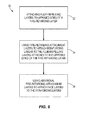
- Figure 6 is a flowchart illustrating one embodiment of a method 30 of manufacturing a fire-retarding apparatus comprising a composite.
- the method may be varied to manufacture any of the embodiments of the fire-retarding apparatus disclosed herein, or varied further to manufacturing varying fire-retarding apparatus having a varying combination of layers.
- fluid-repelling layers may be attached to opposed sides of a fire-retarding layer.
- fire-retarding attachment layers may be used to attach reinforcing layers to the fluid-repelling layers attached to the opposed sides of the fire-retarding layer.
- any of the layers may be attached to one another through/using pressing, adhesives, tape, threads, screws, bolts, fasteners, rivets, staples, clamps, other mechanical members, or other attachment mechanisms.
- a reinforcing material may be embedded within the fire-retarding layer.
- additional fire-retarding attachment layers may be used to attach face layers to the reinforcing layers.
- fluid-repelling layers may be attached to the face layers.
- one or more steps of the method 30 may be varied in substance or in order, one or more steps of the method 30 may not be followed, or one or more additional steps may be added to the method 30.
- the method 30 may be used to manufacture a fire-retarding apparatus having any of the layers varied in order or number, having one or more of the layers not being present, or having one or more additional layers.
- the method 30 may be used to manufacture a fire-retarding apparatus consisting of any combination of the layers including all of the layers or taking away one or more of the layers.
- One or more embodiments of the disclosure may allow for composite apparatus to be made fire-retarding while keeping the fire-retarding composite apparatus low-weight. This is a significant advantage in the airline industry where low weight leads to greater fuel efficiency thereby saving cost.
Landscapes
- Laminated Bodies (AREA)
- Building Environments (AREA)
Abstract
Description
- This disclosure relates to fire-retarding apparatus comprising composites and to their methods of manufacture.
- It is sometimes needed to make apparatus fire-retarding. This is often done using heavy metal construction using materials such as Steel, Titanium, Inconel, and other materials. However, use of such materials increases weight and expense. This is an important issue in the aircraft industry where weight and cost reduction is needed.
- A fire-retarding apparatus and method of manufacture is needed to resolve one or more issues of one or more current fire-retarding apparatus or methods of manufacture.
- In one embodiment, a fire-retarding apparatus is disclosed. The fire-retarding apparatus includes a composite. The composite includes a face layer attached to a fire-retarding layer.
- In another embodiment, a fire-retarding apparatus is disclosed. The fire-retarding apparatus includes a composite. The composite includes a face layer, a fire-retarding layer, a fire-retarding attachment member or fire-retarding attachment layer attaching the face layer to the fire-retarding layer, and a reinforcing layer attached to the fire-retarding layer or reinforcing material embedded in the fire-retarding layer.
- In still another embodiment, a method of manufacturing a fire-retarding apparatus is disclosed. A fire-retarding layer is attached to a face layer to form a composite.
- Further, the disclosure comprises embodiments according to the following clauses:
- Clause 1. A fire-retarding apparatus comprising:
- a composite comprising a face layer attached to a fire-retarding layer.
-
Clause 2. The fire-retarding apparatus of clause 1 wherein the face layer is non-fire-retarding. - Clause 3. The fire-retarding apparatus of clause 1 wherein the face layer comprises metal, non-metallic, composite, polyimide, or a fluid repellant coating.
- Clause 4. The fire-retarding apparatus of clause 1 wherein the fire-retarding layer comprises metal, non-metallic, composite, ceramic, aerogel, xerogel, polyimide, mineral wool, (4, 4-Oxydiphenylene-pyromellitmide), ceramic paste, ceramic coating, or an inorganic material.
- Clause 5. The fire-retarding apparatus of clause 1 further comprising a fire-retarding attachment member or fire-retarding attachment layer attaching the face layer to the fire-retarding layer.
- Clause 6 The fire-retarding apparatus of clause 5 wherein the fire-retarding attachment member or the fire-retarding attachment layer comprises pressed layers, adhesives, tape, fasteners, fire retarding clamps, fire retarding securement members, threads, screws, bolts, fasteners, rivets, clamps, or staples
- Clause 7. The fire-retarding apparatus of clause 1 further comprising a second face layer, wherein the fire-retarding layer is attached between the face layer and the second face layer.
- Clause 8. The fire-retarding apparatus of clause 1 further comprising a reinforcing layer attached to the fire-retarding layer.
- Clause 9. The fire-retarding apparatus of clause 8 wherein the reinforcing layer comprises metal, non-metallic, composite, glass, ceramic, rubber, foam, Aramid, a solid material, a fibrous material, or a porous material.
-
Clause 10. The fire-retarding apparatus of clause 1 wherein the fire-retarding layer further comprises reinforcing material embedded in the fire-retarding layer. - Clause 11. The fire-retarding apparatus of
clause 10 wherein the reinforcing material comprises metal, non-metallic, composite, glass, ceramic, rubber, foam, Aramid, a solid material, a fibrous material, or a porous material. -
Clause 12. The fire-retarding apparatus of clause 1 further comprising a fluid-repelling layer attached to the face layer or the fire-retarding layer. - Clause 13. The fire-retarding apparatus of
clause 12 wherein the fluid-repelling layer comprises silicone, or a nano-coating. -
Clause 14. The fire-retarding apparatus of clause 1 wherein the fire-retarding apparatus weighs less than one pound per square foot and has a thickness of less than eight inches. - Clause 15. The fire-retarding apparatus of clause 1 wherein the fire-retarding apparatus comprises a portion of an aircraft, a portion of a spacecraft, or a portion of a vehicle.
-
Clause 16. A fire-retarding apparatus comprising:- a composite comprising a face layer, a fire-retarding layer, a fire-retarding attachment member or fire-retarding attachment layer attaching the face layer to the fire-retarding layer, and a reinforcing layer attached to the fire-retarding layer or reinforcing material embedded in the fire-retarding layer.
- Clause 17. The fire-retarding apparatus of
clause 16 wherein the composite further comprises a fluid-repelling layer attached to the face layer, the fire-retarding layer, or the reinforcing layer. -
Clause 18. The fire-retarding apparatus ofclause 16 wherein the fire-retarding apparatus weighs less than one pound per square foot and has a thickness of less than eight inches. - Clause 19. The fire-retarding apparatus of
clause 16 wherein the fire-retarding apparatus comprises a portion of an aircraft, a portion of a spacecraft, or a portion of a vehicle. -
Clause 20. A method of manufacturing a fire-retarding apparatus comprising:- attaching a fire-retarding layer to a face layer to form a composite.
- Clause 21. The method of
clause 20 further comprising attaching the fire-retarding layer to the face layer with a fire-retarding attachment member or with a fire-retarding attachment layer. -
Clause 22. The method ofclause 20 further comprising attaching the fire-retarding layer between the face layer and a second face layer. - Clause 23. The method of
clause 20 further comprising attaching a reinforcing layer to the fire-retarding layer. - Clause 24. The method of
clause 20 further comprising embedding a reinforcing material in the fire-retarding layer. - Clause 25. The method of
clause 20 further comprising attaching a fluid-repelling layer to the face layer or to the fire-retarding layer. - Clause 26. The method of
clause 20 further comprising the formed composite weighing less than one pound per square foot and having a thickness of less than eight inches. - Clause 27. The method of
clause 20 further comprising the formed composite comprising a portion of an aircraft, a portion of a spacecraft, or a portion of a vehicle. - The scope of the present disclosure is defined solely by the appended claims and is not affected by the statements within this summary.
- The disclosure can be better understood with reference to the following drawings and description. The components in the figures are not necessarily to scale, emphasis instead being placed upon illustrating the principles of the disclosure.
-
Figure 1 illustrates a perspective view of a fire-retarding apparatus; -
Figure 2 illustrates a cross-section view through line 2-2 of the fire-retarding apparatus ofFigure 1 ; -
Figure 3 illustrates another embodiment of a cross-section view through line 2-2 in the fire-retarding apparatus ofFigure 1 ; -
Figure 4 illustrates still another embodiment of a cross-section view through line 2-2 in the fire-retarding apparatus ofFigure 1 ; -
Figure 5 illustrates yet another embodiment of a cross-section view through line 2-2 in the fire-retarding apparatus ofFigure 1 ; and -
Figure 6 is a flowchart illustrating one embodiment of a method of manufacturing a fire-retarding apparatus comprising a composite. -
Figure 1 illustrates a perspective view of a fire-retardingapparatus 10. The fire-retardingapparatus 10 may comprise a portion of an aircraft, a portion of a spacecraft, a portion of a vehicle, or another type of apparatus for which it is desired to be fire-retarding. For instance, in an aircraft, the fire-retardingapparatus 10 may comprise any portion of the aircraft which needs to be made fire-retarding such as the engine cowling, a nacelle which holds the engine, a cargo compartment, a housing which holds an airplane component, a skin of the aircraft, a fuselage, or another portion of the aircraft. In other embodiments, the fire-retardingapparatus 10 may further vary. The fire-retardingapparatus 10 may weigh less than 100 pounds per square foot, and may have a thickness t (shown inFigure 2 ) of less than 3 feet. In other embodiments, the fire-retardingapparatus 10 may weigh less than 1 pound per square foot, and may have a thickness t (shown inFigure 2 ) of less than 8 inches. In still other embodiments, the weight and thickness of the fire-retardingapparatus 10 may vary further. -
Figure 2 illustrates a cross-section view through line 2-2 of the fire-retardingapparatus 10 ofFigure 1 . The fire-retardingapparatus 10 may comprise a composite 12. The composite 12 may comprise the following attached layers:face layer 14; fire-retardingattachment layer 16; reinforcinglayer 18; fire-retardingattachment layer 16a; fluid-repellinglayer 20; fire-retardinglayer 22; fluid-repelling layer 20a; fire-retardingattachment layer 16b; reinforcinglayer 18a; fire-retardingattachment layer 16c; andface layer 14a. In other embodiments, any of the layers may vary in order or number, one or more of the layers may not be present, or one or more additional layers may be used. In still other embodiments, the fire-retardingapparatus 10 may consist of any combination of the layers including all of the layers or taking away one or more of the layers. - The face layers 14 and 14a may comprise non-fire-retarding layers. The face layers may comprise sheets of aluminum, composite, metal, non-metallic, polyimide, fluid repelling, or another type of material. In other embodiments, the face layers 14 and 14a may be made of any type of non-fire-retarding or fire-retarding material.
- The fire-retarding attachment layers 16, 16a, 16b, and 16c may be used to adhere the layers disposed on opposite sides of them together, using a material which is fire-retarding. For purposes of this disclosure, the term "fire-retarding" means that the layer or member is made of a material which retards fire, or which doesn't ignite or contains the fire, which prevents the fire from spreading or penetrating through, and which either suppresses the fire or extinguishes it through containment and/or lack of oxygen. The fire-retarding attachment layers 16, 16a, 16b, and 16c may comprise an adhesive, paste, solid, or another adhering material which is fire-retarding. The fire-retarding attachment layers 16, 16a, 16b, and 16c may be made of ceramic, metal, non-metallic, composite, Aramid, aerogel, or polyimide. In other embodiments, the fire-retarding attachment layers 16, 16a, 16b, and 16c may be made of varying materials which both adhere the layers disposed on opposite sides of them together, and are fire-retarding having fire retarding properties equivalent to Underwriter Laboratories (UL) Rating of UL-94 V-0 (does not burn) with an operating temperature range of -452 degrees F to 3,600 degrees F. In additional embodiments, the fire-retarding attachment layers 16, 16a, 16b, and 16c may survive a fire of 2,000 degrees Fahrenheit minimum for 15 minutes without burning through and without burning the back or front sides. In still other embodiments, the fire-retarding attachment layers 16, 16a, 16b, and 16c may vary further. In one embodiment, the fire-retarding attachment layers 16, 16a, 16b, and 16c may comprise one or more fire-retarding attachment members which are used to attach layers. The fire-retarding attachment members may comprise fire-retarding fasteners, fire-retarding clamps, fire-retarding securement members, or other types of fire-retarding attachment members. In other embodiments, any of the layers of the fire-retarding
apparatus 10 may be attached to one another through/using pressing, adhesives, tape, threads, screws, bolts, fasteners, rivets, staples, clamps, other mechanical members, or other attachment mechanisms. - The reinforcing layers 18 and 18a provide reinforcement and strength to the fire-retarding
layer 22 to reduce the likelihood of the fire-retardinglayer 22 tearing or disintegrating. The reinforcing layers 18 and 18a may be made of metal, non-metallic, ceramic, glass, composite, rubber, foam, Aramid, solid, fibrous material, or porous material. In other embodiments, the reinforcinglayers layers layers layer 22 to provide reinforcement and strength to the fire-retardinglayer 22. The reinforcing material may comprise metal, non-metallic, ceramic, glass, composite, foam, rubber, or Aramid. In other embodiments, the reinforcing material may vary. Throughout this disclosure, any time the term "reinforcing" is used or a reference is made to reinforcement properties, the disclosure of this paragraph applies to the term. - The fluid-repelling
layers layer 22 and prevent fluid absorption. For purposes of this disclosure, the term "fluid-repelling" is defined as preventing fluid from being absorbed by the base material. The fluid-repellinglayers layers layers 20 and 2a may have varying fluid repellency. Throughout this disclosure, any time the term "fluid-repelling" is used or a reference is made to fluid-repelling properties, the disclosure of this paragraph applies to the term. - The fire-retarding
layer 22 comprises a material which retards fire, which doesn't ignite and contains the fire, which prevents the fire from spreading or burning through, and which either suppresses the fire or extinguishes it through containment and/or lack of oxygen. The fire-retardinglayer 22 may be made of metal, non-metallic, composite, ceramic, aerogel (organic and inorganic), xerogel (organic and inorganic), polyimide, (4, 4-Oxydiphenylene-Pyromellitmide), mineral wool, ceramic paste, ceramic coating, or an inorganic material. In other embodiments, the fire-retardinglayer 22 may be made of varying materials, such as a high-temperature paste which is applied and cured, which have fire retarding properties equivalent to Underwriter Laboratories (UL) Rating of UL-94 V-0 (does not burn) and an operating temperature range between -100 degrees F to 3,600 degrees F. In additional embodiments, the fire-retardinglayer 22 may survive a fire of 2,000 degrees Fahrenheit minimum for 15 minutes without burning through and without burning the back or front sides. In still other embodiments, the fire-retardingattachment layer 22 may vary further. -
Figure 3 illustrates another embodiment of a cross-section view through line 2-2 in the fire-retardingapparatus 10 ofFigure 1 . As shown, in this embodiment the fire-retardingapparatus 10 comprises a composite 12 which includes the following attached layers:face layer 14; fire-retardingattachment layer 16; fire-retardinglayer 22; fire-retardingattachment layer 16c; andface layer 14a. Reinforcinglayer 18, fire-retardingattachment layer 16a, fluid-repellinglayer 20, fluid-repelling layer 20a, fire-retardingattachment layer 16b, and reinforcinglayer 18a have been eliminated from the cross-sectional embodiment ofFigure 2 . In other embodiments, any of the layers may vary in order or number, one or more of the layers may not be present, or one or more additional layers may be used. In still other embodiments, the fire-retardingapparatus 10 may consist of any combination of the layers including all of the layers or taking away one or more of the layers. -
Figure 4 illustrates still another embodiment of a cross-section view through line 2-2 in the fire-retardingapparatus 10 ofFigure 1 . As shown, in this embodiment the fire-retardingapparatus 10 comprises a composite 12 which includes the following attached layers: fluid-repellinglayer 20; fire-retardinglayer 22; fluid-repelling layer 20a; fire-retardingattachment layer 16c; andface layer 14a.Face layer 14, fire-retardingattachment layer 16, reinforcinglayer 18, fire-retardingattachment layer 16a, fire-retardingattachment layer 16b, and reinforcinglayer 18a have been eliminated from the cross-sectional embodiment ofFigure 2 . In other embodiments, any of the layers may vary in order or number, one or more of the layers may not be present, or one or more additional layers may be used. In still other embodiments, the fire-retardingapparatus 10 may consist of any combination of the layers including all of the layers or taking away one or more of the layers. -
Figure 5 illustrates yet another embodiment of a cross-section view through line 2-2 in the fire-retardingapparatus 10 ofFigure 1 . As shown, in this embodiment the fire-retardingapparatus 10 comprises a composite 12 which includes the following attached layers: fire-retardinglayer 22; andface layer 14a.Face layer 14, fire-retardingattachment layer 16, reinforcinglayer 18, fire-retardingattachment layer 16a, fluid-repellinglayer 20, fluid-repelling layer 20a, fire-retardingattachment layer 16b, reinforcinglayer 18a, and fire-retardingattachment layer 16c have been eliminated from the cross-sectional embodiment ofFigure 2 . In other embodiments, any of the layers may vary in order or number, one or more of the layers may not be present, or one or more additional layers may be used. In still other embodiments, the fire-retardingapparatus 10 may consist of any combination of the layers including all of the layers or taking away one or more of the layers. -
Figure 6 is a flowchart illustrating one embodiment of amethod 30 of manufacturing a fire-retarding apparatus comprising a composite. The method may be varied to manufacture any of the embodiments of the fire-retarding apparatus disclosed herein, or varied further to manufacturing varying fire-retarding apparatus having a varying combination of layers. Instep 32, fluid-repelling layers may be attached to opposed sides of a fire-retarding layer. Instep 34, fire-retarding attachment layers may be used to attach reinforcing layers to the fluid-repelling layers attached to the opposed sides of the fire-retarding layer. In other embodiments, any of the layers may be attached to one another through/using pressing, adhesives, tape, threads, screws, bolts, fasteners, rivets, staples, clamps, other mechanical members, or other attachment mechanisms. In still other embodiments, rather than attaching fire-retarding attachment layers, a reinforcing material may be embedded within the fire-retarding layer. Instep 36, additional fire-retarding attachment layers may be used to attach face layers to the reinforcing layers. Optionally, fluid-repelling layers may be attached to the face layers. - In other embodiments, one or more steps of the
method 30 may be varied in substance or in order, one or more steps of themethod 30 may not be followed, or one or more additional steps may be added to themethod 30. In still other embodiments, themethod 30 may be used to manufacture a fire-retarding apparatus having any of the layers varied in order or number, having one or more of the layers not being present, or having one or more additional layers. In additional embodiments, themethod 30 may be used to manufacture a fire-retarding apparatus consisting of any combination of the layers including all of the layers or taking away one or more of the layers. - One or more embodiments of the disclosure may allow for composite apparatus to be made fire-retarding while keeping the fire-retarding composite apparatus low-weight. This is a significant advantage in the airline industry where low weight leads to greater fuel efficiency thereby saving cost.
- The Abstract is provided to allow the reader to quickly ascertain the nature of the technical disclosure. It is submitted with the understanding that it will not be used to interpret or limit the scope or meaning of the claims. In addition, in the foregoing Detailed Description, it can be seen that various features are grouped together in various embodiments for the purpose of streamlining the disclosure. This method of disclosure is not to be interpreted as reflecting an intention that the claimed embodiments require more features than are expressly recited in each claim. Rather, as the following claims reflect, inventive subject matter lies in less than all features of a single disclosed embodiment. Thus the following claims are hereby incorporated into the Detailed Description, with each claim standing on its own as a separately claimed subject matter.
- While particular aspects of the present subject matter described herein have been shown and described, it will be apparent to those skilled in the art that, based upon the teachings herein, changes and modifications may be made without departing from the subject matter described herein and its broader aspects and, therefore, the appended claims are to encompass within their scope all such changes and modifications as are within the true scope of the subject matter described herein. Furthermore, it is to be understood that the disclosure is defined by the appended claims. Accordingly, the disclosure is not to be restricted except in light of the appended claims and their equivalents.
Claims (15)
- A fire-retarding apparatus (10) comprising:a composite (12) comprising a face layer (14) attached to a fire-retarding layer (22).
- The fire-retarding apparatus (10) of claim 1 wherein the fire-retarding layer (22) comprises metal, non-metallic, composite, ceramic, aerogel, xerogel, polyimide, mineral wool, (4, 4-Oxydiphenylene-pyromellitmide), ceramic paste, ceramic coating, or an inorganic material.
- The fire-retarding apparatus (10) of claim 1 further comprising a fire-retarding attachment member or fire-retarding attachment layer (16) attaching the face layer (14) to the fire-retarding layer(22).
- The fire-retarding apparatus (10) of claim 1 further comprising a second face layer (14a), wherein the fire-retarding layer (22) is attached between the face layer and the second face layer (14a).
- The fire-retarding apparatus (10) of claim 1 further comprising a reinforcing layer (18) attached to the fire-retarding layer (22).
- The fire-retarding apparatus (10) of claim 1 wherein the fire-retarding layer (22) further comprises reinforcing material embedded in the fire-retarding layer (22).
- The fire-retarding apparatus (10) of claim 1 further comprising a fluid-repelling layer (20) attached to the face layer (14) or the fire-retarding layer (22).
- A method of manufacturing a fire-retarding apparatus (10) comprising:attaching a fire-retarding layer (22) to a face layer (14) to form a composite.
- The method of claim 8 further comprising attaching the fire-retarding layer (22) to the face layer (14)with a fire-retarding attachment member or with a fire-retarding attachment layer (16).
- The method of claim 8 further comprising attaching the fire-retarding layer (22) between the face layer(14) and a second face layer (14a).
- The method of claim 8 further comprising attaching a reinforcing layer (18) to the fire-retarding layer (22).
- The method of claim 8 further comprising embedding a reinforcing material in the fire-retarding layer (22).
- The method of claim 8 further comprising attaching a fluid-repelling layer(20)to the face layer or to the fire-retarding layer (22).
- The method of claim 8 further comprising the formed composite (12) weighing less than one pound per square foot and having a thickness of less than eight inches.
- The method of claim 8 further comprising the formed composite (12) comprising a portion of an aircraft, a portion of a spacecraft, or a portion of a vehicle.
Applications Claiming Priority (1)
| Application Number | Priority Date | Filing Date | Title |
|---|---|---|---|
| US14/523,741 US20150297923A1 (en) | 2013-09-09 | 2014-10-24 | Fire-retarding apparatus and methods of their manufacture |
Publications (2)
| Publication Number | Publication Date |
|---|---|
| EP3012098A1 true EP3012098A1 (en) | 2016-04-27 |
| EP3012098B1 EP3012098B1 (en) | 2021-12-29 |
Family
ID=54557206
Family Applications (1)
| Application Number | Title | Priority Date | Filing Date |
|---|---|---|---|
| EP15186828.8A Active EP3012098B1 (en) | 2014-10-24 | 2015-09-25 | Fire-retarding apparatus and methods of their manufacture |
Country Status (4)
| Country | Link |
|---|---|
| EP (1) | EP3012098B1 (en) |
| JP (1) | JP6765801B2 (en) |
| AU (1) | AU2015230866B2 (en) |
| CA (1) | CA2905919C (en) |
Citations (4)
| Publication number | Priority date | Publication date | Assignee | Title |
|---|---|---|---|---|
| US4100860A (en) * | 1971-08-13 | 1978-07-18 | Nuclear Engineering Co., Inc. | Safe transporation of hazardous materials |
| EP0520745A1 (en) * | 1991-06-25 | 1992-12-30 | Lite Flite Limited | Air cargo containers |
| CN1923637A (en) * | 2005-09-01 | 2007-03-07 | 普罗特克纳有限公司 | Plastic transport and storage container |
| EP2853508A2 (en) * | 2013-09-09 | 2015-04-01 | The Boeing Company | Fire-retaining containers |
Family Cites Families (9)
| Publication number | Priority date | Publication date | Assignee | Title |
|---|---|---|---|---|
| JPH08142246A (en) * | 1994-11-22 | 1996-06-04 | Unitika Glass Fiber Kk | Structure of surface material |
| US6670291B1 (en) * | 2000-10-18 | 2003-12-30 | 3M Innovative Properties Company | Laminate sheet material for fire barrier applications |
| US20070141343A1 (en) * | 2005-12-21 | 2007-06-21 | Miller Douglas J | Carbon foam structural insulated panel |
| US20110091713A1 (en) * | 2005-12-21 | 2011-04-21 | Miller Douglas J | Fire Resistant Composite Panel |
| US8443922B2 (en) * | 2009-10-07 | 2013-05-21 | The Boeing Company | Containment device and method for containing energy storage devices |
| US20130129963A1 (en) * | 2011-11-18 | 2013-05-23 | Unifrax I Llc | Fire barrier layer and fire barrier film laminate |
| US9415248B2 (en) * | 2012-04-05 | 2016-08-16 | The Boeing Company | Fire extinguishment container |
| JP6036350B2 (en) * | 2013-02-01 | 2016-11-30 | 王子ホールディングス株式会社 | Aluminum coated composite panel |
| JP2016513030A (en) * | 2013-02-05 | 2016-05-12 | イー・アイ・デュポン・ドウ・ヌムール・アンド・カンパニーE.I.Du Pont De Nemours And Company | Composite sheet and cargo container containing it |
-
2015
- 2015-09-24 CA CA2905919A patent/CA2905919C/en active Active
- 2015-09-25 EP EP15186828.8A patent/EP3012098B1/en active Active
- 2015-09-29 AU AU2015230866A patent/AU2015230866B2/en active Active
- 2015-10-22 JP JP2015208038A patent/JP6765801B2/en active Active
Patent Citations (4)
| Publication number | Priority date | Publication date | Assignee | Title |
|---|---|---|---|---|
| US4100860A (en) * | 1971-08-13 | 1978-07-18 | Nuclear Engineering Co., Inc. | Safe transporation of hazardous materials |
| EP0520745A1 (en) * | 1991-06-25 | 1992-12-30 | Lite Flite Limited | Air cargo containers |
| CN1923637A (en) * | 2005-09-01 | 2007-03-07 | 普罗特克纳有限公司 | Plastic transport and storage container |
| EP2853508A2 (en) * | 2013-09-09 | 2015-04-01 | The Boeing Company | Fire-retaining containers |
Also Published As
| Publication number | Publication date |
|---|---|
| JP2016104557A (en) | 2016-06-09 |
| EP3012098B1 (en) | 2021-12-29 |
| CA2905919A1 (en) | 2016-04-24 |
| JP6765801B2 (en) | 2020-10-07 |
| CA2905919C (en) | 2020-02-04 |
| AU2015230866B2 (en) | 2019-04-18 |
Similar Documents
| Publication | Publication Date | Title |
|---|---|---|
| Sadoun et al. | Effect of through-the-thickness position of aluminum wire mesh on the mechanical properties of GFRP/Al hybrid composites | |
| Aktaş et al. | Compression-after impact behavior of laminated composite plates subjected to low velocity impact in high temperatures | |
| Alderliesten et al. | The applicability of magnesium based fibre metal laminates in aerospace structures | |
| Christke et al. | Multi-layer polymer metal laminates for the fire protection of lightweight structures | |
| CN100418850C (en) | Fuselage body | |
| US8524356B1 (en) | Bonded patch having multiple zones of fracture toughness | |
| Shafizadeh et al. | Evaluation of the in-service performance behavior of honeycomb composite sandwich structures | |
| JP2016520458A (en) | Composite panel for floor or wall covering parts and method for manufacturing such a panel | |
| Straznicky et al. | Applications of fiber‐metal laminates | |
| EP3636427B1 (en) | Fireproof and thermal insulator product | |
| Schonberg | Protecting spacecraft against orbital debris impact damage using composite materials | |
| CN112793244A (en) | Fire and Insulation Products | |
| EP1701881B1 (en) | Aircraft fuselage | |
| Johnson et al. | Applications of Fracture Mechanics to the Durability of Bonded Composite Joints. | |
| Li et al. | An investigation into the fatigue of a hybrid titanium composite laminate | |
| US20150297923A1 (en) | Fire-retarding apparatus and methods of their manufacture | |
| JP2007517711A5 (en) | ||
| CA2905919C (en) | Fire-retarding apparatus and methods of their manufacture | |
| US5418050A (en) | Fire/heat barrier laminates | |
| Lamani et al. | Analysis, fabrication and testing of a sandwich composite for an UAV wing | |
| RU2676637C1 (en) | Fire-resistant layered metal glass plastic and a product made from it | |
| Dincă et al. | Aluminum/glass fibre and aluminum/carbon fibre hybrid laminates | |
| Shestov et al. | Structural laminate aluminum-glass-fiber materials 1441-SIAL | |
| Sagomonova et al. | Application of adhesives in the composition of vibration-absorbing materials | |
| Mohammed | A Review of New Composite Materials for Thermal Protection in an Aero-Engine Application |
Legal Events
| Date | Code | Title | Description |
|---|---|---|---|
| PUAI | Public reference made under article 153(3) epc to a published international application that has entered the european phase |
Free format text: ORIGINAL CODE: 0009012 |
|
| 17P | Request for examination filed |
Effective date: 20150925 |
|
| AK | Designated contracting states |
Kind code of ref document: A1 Designated state(s): AL AT BE BG CH CY CZ DE DK EE ES FI FR GB GR HR HU IE IS IT LI LT LU LV MC MK MT NL NO PL PT RO RS SE SI SK SM TR |
|
| AX | Request for extension of the european patent |
Extension state: BA ME |
|
| RBV | Designated contracting states (corrected) |
Designated state(s): AL AT BE BG CH CY CZ DE DK EE ES FI FR GB GR HR HU IE IS IT LI LT LU LV MC MK MT NL NO PL PT RO RS SE SI SK SM TR |
|
| STAA | Information on the status of an ep patent application or granted ep patent |
Free format text: STATUS: EXAMINATION IS IN PROGRESS |
|
| 17Q | First examination report despatched |
Effective date: 20190910 |
|
| GRAP | Despatch of communication of intention to grant a patent |
Free format text: ORIGINAL CODE: EPIDOSNIGR1 |
|
| STAA | Information on the status of an ep patent application or granted ep patent |
Free format text: STATUS: GRANT OF PATENT IS INTENDED |
|
| INTG | Intention to grant announced |
Effective date: 20210720 |
|
| GRAS | Grant fee paid |
Free format text: ORIGINAL CODE: EPIDOSNIGR3 |
|
| GRAA | (expected) grant |
Free format text: ORIGINAL CODE: 0009210 |
|
| STAA | Information on the status of an ep patent application or granted ep patent |
Free format text: STATUS: THE PATENT HAS BEEN GRANTED |
|
| AK | Designated contracting states |
Kind code of ref document: B1 Designated state(s): AL AT BE BG CH CY CZ DE DK EE ES FI FR GB GR HR HU IE IS IT LI LT LU LV MC MK MT NL NO PL PT RO RS SE SI SK SM TR |
|
| REG | Reference to a national code |
Ref country code: GB Ref legal event code: FG4D |
|
| REG | Reference to a national code |
Ref country code: CH Ref legal event code: EP |
|
| REG | Reference to a national code |
Ref country code: AT Ref legal event code: REF Ref document number: 1458384 Country of ref document: AT Kind code of ref document: T Effective date: 20220115 |
|
| REG | Reference to a national code |
Ref country code: IE Ref legal event code: FG4D |
|
| REG | Reference to a national code |
Ref country code: DE Ref legal event code: R096 Ref document number: 602015076025 Country of ref document: DE |
|
| REG | Reference to a national code |
Ref country code: LT Ref legal event code: MG9D |
|
| PG25 | Lapsed in a contracting state [announced via postgrant information from national office to epo] |
Ref country code: RS Free format text: LAPSE BECAUSE OF FAILURE TO SUBMIT A TRANSLATION OF THE DESCRIPTION OR TO PAY THE FEE WITHIN THE PRESCRIBED TIME-LIMIT Effective date: 20211229 Ref country code: LT Free format text: LAPSE BECAUSE OF FAILURE TO SUBMIT A TRANSLATION OF THE DESCRIPTION OR TO PAY THE FEE WITHIN THE PRESCRIBED TIME-LIMIT Effective date: 20211229 Ref country code: FI Free format text: LAPSE BECAUSE OF FAILURE TO SUBMIT A TRANSLATION OF THE DESCRIPTION OR TO PAY THE FEE WITHIN THE PRESCRIBED TIME-LIMIT Effective date: 20211229 Ref country code: BG Free format text: LAPSE BECAUSE OF FAILURE TO SUBMIT A TRANSLATION OF THE DESCRIPTION OR TO PAY THE FEE WITHIN THE PRESCRIBED TIME-LIMIT Effective date: 20220329 |
|
| REG | Reference to a national code |
Ref country code: NL Ref legal event code: MP Effective date: 20211229 |
|
| REG | Reference to a national code |
Ref country code: AT Ref legal event code: MK05 Ref document number: 1458384 Country of ref document: AT Kind code of ref document: T Effective date: 20211229 |
|
| PG25 | Lapsed in a contracting state [announced via postgrant information from national office to epo] |
Ref country code: SE Free format text: LAPSE BECAUSE OF FAILURE TO SUBMIT A TRANSLATION OF THE DESCRIPTION OR TO PAY THE FEE WITHIN THE PRESCRIBED TIME-LIMIT Effective date: 20211229 Ref country code: NO Free format text: LAPSE BECAUSE OF FAILURE TO SUBMIT A TRANSLATION OF THE DESCRIPTION OR TO PAY THE FEE WITHIN THE PRESCRIBED TIME-LIMIT Effective date: 20220329 Ref country code: LV Free format text: LAPSE BECAUSE OF FAILURE TO SUBMIT A TRANSLATION OF THE DESCRIPTION OR TO PAY THE FEE WITHIN THE PRESCRIBED TIME-LIMIT Effective date: 20211229 Ref country code: HR Free format text: LAPSE BECAUSE OF FAILURE TO SUBMIT A TRANSLATION OF THE DESCRIPTION OR TO PAY THE FEE WITHIN THE PRESCRIBED TIME-LIMIT Effective date: 20211229 Ref country code: GR Free format text: LAPSE BECAUSE OF FAILURE TO SUBMIT A TRANSLATION OF THE DESCRIPTION OR TO PAY THE FEE WITHIN THE PRESCRIBED TIME-LIMIT Effective date: 20220330 |
|
| PG25 | Lapsed in a contracting state [announced via postgrant information from national office to epo] |
Ref country code: NL Free format text: LAPSE BECAUSE OF FAILURE TO SUBMIT A TRANSLATION OF THE DESCRIPTION OR TO PAY THE FEE WITHIN THE PRESCRIBED TIME-LIMIT Effective date: 20211229 |
|
| PG25 | Lapsed in a contracting state [announced via postgrant information from national office to epo] |
Ref country code: SM Free format text: LAPSE BECAUSE OF FAILURE TO SUBMIT A TRANSLATION OF THE DESCRIPTION OR TO PAY THE FEE WITHIN THE PRESCRIBED TIME-LIMIT Effective date: 20211229 Ref country code: SK Free format text: LAPSE BECAUSE OF FAILURE TO SUBMIT A TRANSLATION OF THE DESCRIPTION OR TO PAY THE FEE WITHIN THE PRESCRIBED TIME-LIMIT Effective date: 20211229 Ref country code: RO Free format text: LAPSE BECAUSE OF FAILURE TO SUBMIT A TRANSLATION OF THE DESCRIPTION OR TO PAY THE FEE WITHIN THE PRESCRIBED TIME-LIMIT Effective date: 20211229 Ref country code: PT Free format text: LAPSE BECAUSE OF FAILURE TO SUBMIT A TRANSLATION OF THE DESCRIPTION OR TO PAY THE FEE WITHIN THE PRESCRIBED TIME-LIMIT Effective date: 20220429 Ref country code: ES Free format text: LAPSE BECAUSE OF FAILURE TO SUBMIT A TRANSLATION OF THE DESCRIPTION OR TO PAY THE FEE WITHIN THE PRESCRIBED TIME-LIMIT Effective date: 20211229 Ref country code: EE Free format text: LAPSE BECAUSE OF FAILURE TO SUBMIT A TRANSLATION OF THE DESCRIPTION OR TO PAY THE FEE WITHIN THE PRESCRIBED TIME-LIMIT Effective date: 20211229 Ref country code: CZ Free format text: LAPSE BECAUSE OF FAILURE TO SUBMIT A TRANSLATION OF THE DESCRIPTION OR TO PAY THE FEE WITHIN THE PRESCRIBED TIME-LIMIT Effective date: 20211229 |
|
| PG25 | Lapsed in a contracting state [announced via postgrant information from national office to epo] |
Ref country code: PL Free format text: LAPSE BECAUSE OF FAILURE TO SUBMIT A TRANSLATION OF THE DESCRIPTION OR TO PAY THE FEE WITHIN THE PRESCRIBED TIME-LIMIT Effective date: 20211229 Ref country code: AT Free format text: LAPSE BECAUSE OF FAILURE TO SUBMIT A TRANSLATION OF THE DESCRIPTION OR TO PAY THE FEE WITHIN THE PRESCRIBED TIME-LIMIT Effective date: 20211229 |
|
| PG25 | Lapsed in a contracting state [announced via postgrant information from national office to epo] |
Ref country code: IS Free format text: LAPSE BECAUSE OF FAILURE TO SUBMIT A TRANSLATION OF THE DESCRIPTION OR TO PAY THE FEE WITHIN THE PRESCRIBED TIME-LIMIT Effective date: 20220429 |
|
| REG | Reference to a national code |
Ref country code: DE Ref legal event code: R097 Ref document number: 602015076025 Country of ref document: DE |
|
| PG25 | Lapsed in a contracting state [announced via postgrant information from national office to epo] |
Ref country code: DK Free format text: LAPSE BECAUSE OF FAILURE TO SUBMIT A TRANSLATION OF THE DESCRIPTION OR TO PAY THE FEE WITHIN THE PRESCRIBED TIME-LIMIT Effective date: 20211229 Ref country code: AL Free format text: LAPSE BECAUSE OF FAILURE TO SUBMIT A TRANSLATION OF THE DESCRIPTION OR TO PAY THE FEE WITHIN THE PRESCRIBED TIME-LIMIT Effective date: 20211229 |
|
| PLBE | No opposition filed within time limit |
Free format text: ORIGINAL CODE: 0009261 |
|
| STAA | Information on the status of an ep patent application or granted ep patent |
Free format text: STATUS: NO OPPOSITION FILED WITHIN TIME LIMIT |
|
| 26N | No opposition filed |
Effective date: 20220930 |
|
| PG25 | Lapsed in a contracting state [announced via postgrant information from national office to epo] |
Ref country code: SI Free format text: LAPSE BECAUSE OF FAILURE TO SUBMIT A TRANSLATION OF THE DESCRIPTION OR TO PAY THE FEE WITHIN THE PRESCRIBED TIME-LIMIT Effective date: 20211229 |
|
| PG25 | Lapsed in a contracting state [announced via postgrant information from national office to epo] |
Ref country code: MC Free format text: LAPSE BECAUSE OF FAILURE TO SUBMIT A TRANSLATION OF THE DESCRIPTION OR TO PAY THE FEE WITHIN THE PRESCRIBED TIME-LIMIT Effective date: 20211229 |
|
| REG | Reference to a national code |
Ref country code: CH Ref legal event code: PL |
|
| REG | Reference to a national code |
Ref country code: BE Ref legal event code: MM Effective date: 20220930 |
|
| PG25 | Lapsed in a contracting state [announced via postgrant information from national office to epo] |
Ref country code: IT Free format text: LAPSE BECAUSE OF FAILURE TO SUBMIT A TRANSLATION OF THE DESCRIPTION OR TO PAY THE FEE WITHIN THE PRESCRIBED TIME-LIMIT Effective date: 20211229 |
|
| P01 | Opt-out of the competence of the unified patent court (upc) registered |
Effective date: 20230516 |
|
| PG25 | Lapsed in a contracting state [announced via postgrant information from national office to epo] |
Ref country code: LU Free format text: LAPSE BECAUSE OF NON-PAYMENT OF DUE FEES Effective date: 20220925 |
|
| PG25 | Lapsed in a contracting state [announced via postgrant information from national office to epo] |
Ref country code: LI Free format text: LAPSE BECAUSE OF NON-PAYMENT OF DUE FEES Effective date: 20220930 Ref country code: IE Free format text: LAPSE BECAUSE OF NON-PAYMENT OF DUE FEES Effective date: 20220925 Ref country code: CH Free format text: LAPSE BECAUSE OF NON-PAYMENT OF DUE FEES Effective date: 20220930 |
|
| PG25 | Lapsed in a contracting state [announced via postgrant information from national office to epo] |
Ref country code: BE Free format text: LAPSE BECAUSE OF NON-PAYMENT OF DUE FEES Effective date: 20220930 |
|
| PG25 | Lapsed in a contracting state [announced via postgrant information from national office to epo] |
Ref country code: HU Free format text: LAPSE BECAUSE OF FAILURE TO SUBMIT A TRANSLATION OF THE DESCRIPTION OR TO PAY THE FEE WITHIN THE PRESCRIBED TIME-LIMIT; INVALID AB INITIO Effective date: 20150925 |
|
| PG25 | Lapsed in a contracting state [announced via postgrant information from national office to epo] |
Ref country code: CY Free format text: LAPSE BECAUSE OF FAILURE TO SUBMIT A TRANSLATION OF THE DESCRIPTION OR TO PAY THE FEE WITHIN THE PRESCRIBED TIME-LIMIT Effective date: 20211229 |
|
| PG25 | Lapsed in a contracting state [announced via postgrant information from national office to epo] |
Ref country code: MK Free format text: LAPSE BECAUSE OF FAILURE TO SUBMIT A TRANSLATION OF THE DESCRIPTION OR TO PAY THE FEE WITHIN THE PRESCRIBED TIME-LIMIT Effective date: 20211229 |
|
| PG25 | Lapsed in a contracting state [announced via postgrant information from national office to epo] |
Ref country code: TR Free format text: LAPSE BECAUSE OF FAILURE TO SUBMIT A TRANSLATION OF THE DESCRIPTION OR TO PAY THE FEE WITHIN THE PRESCRIBED TIME-LIMIT Effective date: 20211229 |
|
| PG25 | Lapsed in a contracting state [announced via postgrant information from national office to epo] |
Ref country code: MT Free format text: LAPSE BECAUSE OF FAILURE TO SUBMIT A TRANSLATION OF THE DESCRIPTION OR TO PAY THE FEE WITHIN THE PRESCRIBED TIME-LIMIT Effective date: 20211229 |
|
| PGFP | Annual fee paid to national office [announced via postgrant information from national office to epo] |
Ref country code: DE Payment date: 20250929 Year of fee payment: 11 |
|
| PGFP | Annual fee paid to national office [announced via postgrant information from national office to epo] |
Ref country code: GB Payment date: 20250929 Year of fee payment: 11 |
|
| PGFP | Annual fee paid to national office [announced via postgrant information from national office to epo] |
Ref country code: FR Payment date: 20250925 Year of fee payment: 11 |