EP3011995B1 - Mikrosonde zur selektiven elektroportation und herstellungsverfahren solch einer mikrosonde - Google Patents
Mikrosonde zur selektiven elektroportation und herstellungsverfahren solch einer mikrosonde Download PDFInfo
- Publication number
- EP3011995B1 EP3011995B1 EP15183159.1A EP15183159A EP3011995B1 EP 3011995 B1 EP3011995 B1 EP 3011995B1 EP 15183159 A EP15183159 A EP 15183159A EP 3011995 B1 EP3011995 B1 EP 3011995B1
- Authority
- EP
- European Patent Office
- Prior art keywords
- glass
- microprobe
- primary
- primary glass
- diameter
- Prior art date
- Legal status (The legal status is an assumption and is not a legal conclusion. Google has not performed a legal analysis and makes no representation as to the accuracy of the status listed.)
- Active
Links
Images

Classifications
-
- A—HUMAN NECESSITIES
- A61—MEDICAL OR VETERINARY SCIENCE; HYGIENE
- A61N—ELECTROTHERAPY; MAGNETOTHERAPY; RADIATION THERAPY; ULTRASOUND THERAPY
- A61N1/00—Electrotherapy; Circuits therefor
- A61N1/18—Applying electric currents by contact electrodes
- A61N1/32—Applying electric currents by contact electrodes alternating or intermittent currents
- A61N1/327—Applying electric currents by contact electrodes alternating or intermittent currents for enhancing the absorption properties of tissue, e.g. by electroporation
-
- A—HUMAN NECESSITIES
- A61—MEDICAL OR VETERINARY SCIENCE; HYGIENE
- A61N—ELECTROTHERAPY; MAGNETOTHERAPY; RADIATION THERAPY; ULTRASOUND THERAPY
- A61N1/00—Electrotherapy; Circuits therefor
- A61N1/02—Details
- A61N1/04—Electrodes
- A61N1/0404—Electrodes for external use
- A61N1/0408—Use-related aspects
- A61N1/0412—Specially adapted for transcutaneous electroporation, e.g. including drug reservoirs
-
- C—CHEMISTRY; METALLURGY
- C12—BIOCHEMISTRY; BEER; SPIRITS; WINE; VINEGAR; MICROBIOLOGY; ENZYMOLOGY; MUTATION OR GENETIC ENGINEERING
- C12M—APPARATUS FOR ENZYMOLOGY OR MICROBIOLOGY; APPARATUS FOR CULTURING MICROORGANISMS FOR PRODUCING BIOMASS, FOR GROWING CELLS OR FOR OBTAINING FERMENTATION OR METABOLIC PRODUCTS, i.e. BIOREACTORS OR FERMENTERS
- C12M35/00—Means for application of stress for stimulating the growth of microorganisms or the generation of fermentation or metabolic products; Means for electroporation or cell fusion
- C12M35/02—Electrical or electromagnetic means, e.g. for electroporation or for cell fusion
-
- A—HUMAN NECESSITIES
- A61—MEDICAL OR VETERINARY SCIENCE; HYGIENE
- A61B—DIAGNOSIS; SURGERY; IDENTIFICATION
- A61B18/00—Surgical instruments, devices or methods for transferring non-mechanical forms of energy to or from the body
- A61B18/04—Surgical instruments, devices or methods for transferring non-mechanical forms of energy to or from the body by heating
- A61B18/12—Surgical instruments, devices or methods for transferring non-mechanical forms of energy to or from the body by heating by passing a current through the tissue to be heated, e.g. high-frequency current
- A61B18/14—Probes or electrodes therefor
-
- A—HUMAN NECESSITIES
- A61—MEDICAL OR VETERINARY SCIENCE; HYGIENE
- A61B—DIAGNOSIS; SURGERY; IDENTIFICATION
- A61B18/00—Surgical instruments, devices or methods for transferring non-mechanical forms of energy to or from the body
- A61B2018/00571—Surgical instruments, devices or methods for transferring non-mechanical forms of energy to or from the body for achieving a particular surgical effect
- A61B2018/00613—Irreversible electroporation
-
- A—HUMAN NECESSITIES
- A61—MEDICAL OR VETERINARY SCIENCE; HYGIENE
- A61N—ELECTROTHERAPY; MAGNETOTHERAPY; RADIATION THERAPY; ULTRASOUND THERAPY
- A61N1/00—Electrotherapy; Circuits therefor
- A61N1/02—Details
- A61N1/04—Electrodes
- A61N1/0404—Electrodes for external use
- A61N1/0472—Structure-related aspects
- A61N1/048—Electrodes characterised by a specific connection between lead and electrode
Definitions
- Subject of the invention is a microprobe for selective electroporation of chosen cells regions of internal organs in vivo and single cells in vitro and also for additional integration in one device: channel for local drug delivery, imaging channel for observation of region where electroporation is applied, optical fibre for delivery or receiving of illuminating or therapeutic signal.
- Subject of the invention is also method of manufacturing of such a microprobe.
- Electroporation is one of the delivery methods used experimentally to open cell membranes in living organisms and to deliver internally biologically active compounds or to isolate fragments of cells from their interior, e.g. DNA. Method is based on generation of local electromagnetic field what leads to disruption of cell membrane electron structure and generation of channels where molecules can migrate intracellularly [ De Vry, Jochen (2010) In vivo electroporation of the central nervous system: A non-viral approach for targeted gene delivery. Progress in Neurobiology 92(3 )]. Electroporation is used as a experimental method for gene therapy and for treatment of i.a. neoplastic diseases where electric field enables local disintegration of cell membrane and precise delivery of new generation drugs to the malignant cells.
- Probes obtained using lithographic method exhibit low thermal resistance and low bending and stress resistance and their functionality reflected in e.g. drug delivery (through channels in shafts of such probes) is extremely limited.
- EP2497419 (A1 ) publication discloses method for manufacturing of flexible probe with cylindrical cross-section involving lithographic methods for brain cells stimulation.
- Probe according to this publication contains electrodes on its surface which are covered with thin layer of isolating material with 0.5 mm thickness.
- WO/046170A1 patent application specification discloses a highly spatially resolved method for electroporation and parallel delivery of one or several different compounds into cell structures, such as cells, cell-like structures, or a population of cells, wherein at least two electrolyte-filled tubes are provided together with a ground or counter electrode.
- JP2004041434 A publication reveals an electroporation apparatus with a wide space between electrodes and provided with a pulse impressing means generating DC pulse.
- the base end parts of the electrodes are connected to the tip parts of arm parts and composed of super-elastic alloy.
- the shape of the arm parts is restored and opened so that the tip parts of the paired electrodes have a space D larger than the outside diameter of the guide cylinder.
- US2014222123 A1 discloses a nanopillar electrode device and method of recording action potentials with such device.
- the device comprises a substrate patterned with a plurality of metal pads, a plurality of nanopillar electrode arrays, wherein each nanopillar electrode array is attached to the substrate above a metal pad and electrically connected to the metal pad; and a chamber surrounding the nanopillar electrodes.
- the nanopillar electrode device can be used to record both extracellular and intracellular action potentials of cells.
- the methods of certain embodiments described herein may be used for measuring membrane potentials from excitable cells, and may be useful in distinguishing cell types based on the shapes of their action potentials, detecting changes in action potentials induced by drugs that target ion channels, and monitoring differentiation of stem cells into various cell types.
- neuroprobe from US2013/0030274 (A1 ) publication consists of one or more shafts and contains optical source connected with at least one optical fibre stretched on whole length of probe shaft or shafts. Also in this invention lithographic method for probe manufacturing has been utilized what is connected with manufacturing of electrodes on the surface of semiconductive material containing waveguides and metal lines prepared using lithography.
- Preceding solutions do not enable utilizing of electroporation phenomenon to selectively open cell membrane i.e. in case of single cells or in limited regions, for example for electroporation of internal organs. In this way there is a need to develop such a probe, which thanks to smaller dimensions than before, would reach single cells or limited regions in patient body and which would be used as a tool for selective electroporation.
- the subject of the present invention is a microprobe for selective electroporation containing at least two metal electrodes immersed in a glass rod characterised in that the glass rod, which is made of a primary glass, has the diameter 50 ⁇ m to 2 mm, preferably 50 ⁇ m to 500 ⁇ m, the metal electrodes made of a metal alloy are made in form of rods with 1 ⁇ m to 100 ⁇ m in diameter, preferably 20 ⁇ m to 30 ⁇ m, where endings of those rods are exposed, wherein the primary glass and the metal alloy are matched in this way that the temperature difference between the dilatometric softening temperature for primary glass and the melting temperature of metal alloy is not higher than 50°C. Construction of microprobe metal electrodes enables constant transduction of electricity or voltage potential is generated, and are isolated from each other and from surroundings by glass. The whole set is small, integrated, long and in form of a fibre.
- the metal alloy exhibits melting temperature lower than dilatometric softening temperature DTM for the primary glass, wherein preferably dilatometric softening temperature for the primary glass equals at most 610°C.
- DTM dilatometric softening temperature
- metal alloy is silver alloy, preferably silver and tin, for example it is a BAg7(Ag56Sn) alloy.
- BAg7(Ag56Sn) is an alloy with good transmission parameters fitted to dilatometric softening temperature DTM of the primary glass.
- microprobe according to the invention is equipped in at least one air channel for drug delivery, preferably with 2 ⁇ m to 1500 ⁇ m in diameter, located inside the glass rod.
- microprobe according to the present invention is equipped in at least one glass channel, preferably made of secondary glass, for transmission of optical signal, preferably with 1 ⁇ m to 300 ⁇ m in diameter, located inside the glass rod.
- microprobe according to the present invention comprises at least one imaging channel made of a secondary glass for transmission of optical image, preferably 50 ⁇ m to 1500 ⁇ m in diameter, located inside glass rod.
- refractive index n D of the primary glass is lower than refractive index n D of the secondary glass, preferably of least 0.001 lower, and more preferably at least 0.01 lower, and most preferably at least 0.5 lower, for example refractive index n D of primary glass equals 1.51 and refractive index n D of the secondary glass equals at most 2.49.
- the higher index difference the smaller imaging channels and more channels can be inserted in given structure and obtain higher imaging resolution. It is highly important because these kind of glass, so called “thermally fitted”, can be thinned on fibre optic tower (i.e. generate preferable structure in elevated temperature conditions), and after cooling down such a structure will be stable and will not exhibit internal stresses which can lead to spontaneous structure disintegration, and will be resistant to bending.
- linear thermal expansion coefficient of the primary glass and the secondary glass are similar, wherein preferably for the primary glass in 20-300°C temperature range linear thermal expansion coefficient is equal to 84.0 10 -7 K -1 , and in 20-450°C temperature range is equal to 89.0 10 -7 K -1 or preferably, linear expansion coefficient for the secondary glass in 20-300°C temperature range is equal to 89.7 10 -7 K -1 , and in 20-450°C temperature range is equal to 94.5 10 -7 K -1 . It is always preferable that difference between thermal expansion coefficients for the primary glass and the secondary glass was as low as possible. It is important that glass can be treated thermally together (structure thinning in elevated temperature) and subsequently cooled down avoiding generation of high internal structure stresses which could lead to spontaneous disintegration of the structure or under the influence of bending, touch, etc.
- the primary glass can be chosen from the group consisting of SK222, NC-21A, PBG-89, F2 Schott, KB-03 glass or the secondary glass is selected from the group consisting of Zr3/XV, NC-32, NC-41, LLF1 Schott, F2 Schott, PBG-08 (PBG81), F2/1,67/2, PBS-57A glass.
- These are sorts of glass which enable thermal transformation in process of probe manufacturing and are not crystallizing during such a transformation. It is important that each glass from this group is paired thermally with appropriate primary glass.
- the invention also covers a method for manufacturing of microprobe for selective electroporation, especially microprobe according to the preceding claims 1-9, wherein method of thinning is utilized, characterised in that, it covers following steps:
- the metal alloy with melting temperature lower than dilatometric softening temperature DTM of the primary glass is utilized, wherein preferably the metal alloy is silver alloy, preferably silver and tin alloy, for example BAg7 (Ag56Sn) alloy, and dilatometric softening temperature DTM for the primary glass equals 610°C at most.
- linear thermal expansion coefficients of the primary glass and the secondary glass are similar, wherein preferably for the primary glass in 20-300°C temperature range linear thermal expansion coefficient is equal to 84.0 10 -7 K -1 , and in 20-450°C temperature range is equal to 89.0 10 -7 K -1 or preferably, linear expansion coefficient for the secondary glass in 20-300°C temperature range is equal to 89.7 10 -1 K -1 , and in 20-450°C temperature range is equal to 94.5 10 -7 K -1 . It is always preferable that difference between thermal expansion coefficients for the primary glass and the secondary glass is as low as possible. It is important that glass simultaneously can be treated thermally together (structure thinning in elevated temperature) and subsequently cooled down avoiding generation of high internal structure stresses, which could lead to spontaneous disintegration of the structure or under the influence of bending, touch, etc.
- refractive index n D of the primary glass is lower than refractive index n D of the secondary glass, preferably of least 0.001 lower, and more preferably at least 0.01 lower, and most preferably at least 0.5 lower, for example refractive index n D of the primary glass equals 1.51 and refractive index n D of the secondary glass equals at most 2.49.
- the higher index difference the smaller imaging channels and more channels can be inserted in given structure and obtain higher imaging resolution. It is highly important because these kind of glass, so called “thermally fitted”, can be thinned on fibre optic tower (i.e. generate preferable structure in elevated temperature conditions), and after cooling down such a structure will be stable and will not exhibit internal stresses which can lead to spontaneous structure disintegration, and will be resistant to bending.
- the primary glass can be chosen from the group consisting of SK222, NC-21A, PBG-89, F2 Schott, KB-03 glass or the secondary glass selected from the group consisting of Zr3/XV, NC-32, NC-41, LLF1 Schott, F2 Schott, PBG-08 (PBG81), F2/1,67/2, PBS-57A glass.
- These are sorts of glass which enable thermal transformation in process of probe manufacturing and are not crystallizing during such a transformation. It is important that each glass from this group is paired thermally with appropriate primary glass.
- Microprobe according to the invention exhibits monolithic structure in form of fibre and can be utilized for in vivo applications using biopsy needle or for in vitro applications.
- Microprobe parameters according to the present invention i.e. flexibility, resistance to temperature and stresses, are obtained thanks to selection of materials with good rheological characteristics, fitted thermally, integrated in thinning process on fibre optic tower, in order to obtain stable, integrated microprobe structure without internal stresses.
- microprobe according to the present invention can be charged using batteries.
- Method for probe manufacturing enables mass production of probes with identical geometric parameters. Used pulling process, so called drawing down at the fibre optic drawing tower, enables manufacturing of microprobes with length of many meters with identical traverse parameters, which can be further cut on many microprobes of given length.
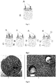
- a - metal electrode B - air channel, C - glass channel, D - imaging channel, E-glass rod.
- Characteristics of the materials are enlisted in Table 1 and 2: Table 1. Characteristics of Bag7 alloy used for construction of GM1A microprobes. Characteristic BAg7 alloy Composition [%] Ag 56 Cu: 22 Zn: 17 Sn: 5 Melting temp. [°C]: 620-650 Density [g/cm 3 ] 9.4 Stretching resistance [kg/mm 2 ] 48 Table 2. Characteristics of glass used for construction of GM1A microprobes.
- Linear thermal expansion coefficients for the primary glass and the secondary glass are similar.
- SK222 glass and Bag7 alloy are chosen due to the alloy melting temperature which is about 50°C lower than temperature of thinning for the glass. That provides metal liquidity during glass capillary stretching and limits generation of gaps in elongated glass-metal rods.
- Relatively high thermal expansion coefficient for the primary glass - SK222 glass (89x10 -7 K -1 for 20-450°C range) lead to the reduction of tensions on glass-metal interface.
- Zr3/XV secondary glass is matched with primary SK222 glass in terms of refractive index and thermal expansion coefficient making imaging channel C for transmission of optical image with good mechanical properties.
- microprobe for electroporation presented on scheme fig. 1 and on the SEM image on fig. 3 is a glass rod E with two integrated metal electrodes A.
- microprobe contains higher amount of metal electrodes A, what is depicted on fig. 2 , being in form of microwires, and immersed in glass rod E.
- Continuous and long metal electrodes A exhibit small diameters equal to 29 ⁇ m and 28 ⁇ m, respectively, and distance between them equals to 37 ⁇ m.
- External diameter of glass rod equals to 458 ⁇ m.
- microprobes are integrated in one unit also with other elements such as imaging channel D for transmission of optical image, glass channel C for transmission of optical signal or air channel B for drug delivery.
- Example 2 Manufacturing of GM1A type microprobe containing glass channel C for transmission of optical image.
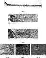
- microprobe was prepared, which is illustrated on Fig. 3 , 350 ⁇ m in diameter and containing metal electrodes A with 20 ⁇ m in diameter. Glass channel C for transmission of optical image is not placed exactly between electrodes, and its translocation happened in the step of preform thinning and is irrelevant for functionality of microprobe manufactured in this manner. Few metal electrode Only few discontinuities of metal electrodes were found in pulled probes. During selection over a dozen of probes 10 to 30 cm long containing continuous metal rods were chosen and selected for further application studies. Parameters of manufactured microprobes are enlisted below in Table 3. Table 3.
- Manufactured microprobes were connected to the external power supply by mounting of microprobes to the plates including mounting of metal electrodes A to the standard electric wires. Mounting of microprobe to the underlay plate was performed using microscope and micromanipulators. Epoxy glue was used. In the next step microelectrodes were connected with microscopic electric wires using Epo-Tek conductive adhesive. Microprobe was heated in oven in 300°C temp. for 15 min. In these conditions glue was hardened. Bonding of A metal electrodes with macroscopic electric wires is depicted on fig. 8 . Rigid microprobe endings were obtained in this way enabling connection to electricity and to microprobe manipulation during experiment. Manufacturing of microprobe electrical connections shown on fig.
- Obtained results show low resistance of metal electrodes A what enables generation difference of potentials between two metal electrodes A without existence of unfavourable heat conditions in microprobe. It is also possible to utilize short electric pulses used in a few electroporation techniques. Obtained results indicate that microprobe has electrodes with homogeneous diameter inside E glass rod. Subsequently, experiments were conducted leading to define breakdown voltage. Tests were conducted in aqueous solution of sodium chloride from zero concentration to obtaining of saturated solution in room temperature (26.5% concentration). Laboratory power adapter with regulated voltage in 0-30 V range was utilized to measure breakdown voltage. Performed tests have given negative results what means that breakdown voltage was higher than 30 V. That enables unconstrained usage of microprobe in aqueous environment (typical for laboratory cell cultures) without worries about breakdown and destruction of samples or microprobe.
- CHO-K1 cells - ATCC® CCL-61TM
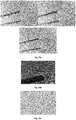
- results of the studies were presented on Fig 9a-c and H9C2 rat cardiac muscle cells were used.
- marker method using Trypan Blue was utilized. In cases of both cell lines it was unequivocally confirmed that electroporation is occurring in single cells in active range of microprobe. Migration of substances from the solution to the cell interior is an indication of occurrence of electroporation. It is possible to observe due to accumulation of marker in the cell which stains it blue.
- Fig 6a-c measurement results of CHO-K1 (ATCC® CCL-61TM) cells electroporation were presented.
- metal electrode A was equal to 156.46 ⁇ m, between its internal edges, and 207.83 ⁇ m between its external walls, metal electrode A thickness was equal to 27.11 ⁇ m, and voltage and current intensity were respectively equal to: 1.7-2 V, 1.9 ⁇ A.
- Fig 10b shows a cell after electroporation using upper electrode in which a stained nucleus is visible. Cells which did not undergo electroporation (so called control cells) show no signs of staining according to the fig. 10c .
Landscapes
- Health & Medical Sciences (AREA)
- Life Sciences & Earth Sciences (AREA)
- Engineering & Computer Science (AREA)
- Bioinformatics & Cheminformatics (AREA)
- General Health & Medical Sciences (AREA)
- Biomedical Technology (AREA)
- Chemical & Material Sciences (AREA)
- Wood Science & Technology (AREA)
- Genetics & Genomics (AREA)
- Biotechnology (AREA)
- Organic Chemistry (AREA)
- Zoology (AREA)
- Biophysics (AREA)
- Nuclear Medicine, Radiotherapy & Molecular Imaging (AREA)
- Veterinary Medicine (AREA)
- Public Health (AREA)
- Animal Behavior & Ethology (AREA)
- Radiology & Medical Imaging (AREA)
- Electromagnetism (AREA)
- Cell Biology (AREA)
- Microbiology (AREA)
- Sustainable Development (AREA)
- General Engineering & Computer Science (AREA)
- Biochemistry (AREA)
- Physics & Mathematics (AREA)
- Apparatus Associated With Microorganisms And Enzymes (AREA)
- Materials For Medical Uses (AREA)
- Electrotherapy Devices (AREA)
- Manufacture, Treatment Of Glass Fibers (AREA)
- Surface Treatment Of Glass (AREA)
- Micromachines (AREA)
Claims (11)
- Mikrosonde zur selektiven Elektroporation, umfassend wenigstens zwei Metallelektroden (A) in einem Glasstab (E) eingetaucht, der aus einem Primärglas hergestellte Glasstab (E) mit 50 µm bis 2 mm im Durchmesser, vorzugsweise 50 µm bis 500 µm, die aus einer Metalllegierung hergestellten Metallelektroden (A) als Stäbe mit einem Durchmesser von 1 µm bis 100 µm, vorzugsweise 20 µm bis 30 µm ausgebildet sind, wobei die Enden dieser Stäbe ausgesetzt sind, wobei das Primärglas und die Metalllegierung so angepasst sind, dass die Temperaturdifferenz zwischen der dilatometrischen Erweichungstemperatur DTM des Primärglases und der Schmelztemperatur der Metalllegierung nicht höher als 50°C ist.
- Mikrosonde nach Anspruch 1, dadurch gekennzeichnet, dass die Metalllegierung eine Schmelztemperatur, die niedriger als die dilatometrische Erweichungstemperatur DTM des Primärglases ist aufweist, wobei vorzugsweise die dilatometrische Erweichungstemperatur DTM des Primärglases höchstens 610°C beträgt.
- Mikrosonde nach Anspruch 1 oder 2, dadurch gekennzeichnet, dass die Metalllegierung eine Silberlegierung ist, vorzugsweise Silber und Zinn, beispielsweise eine BAg7(Ag56Sn)-Legierung ist.
- Mikrosonde nach einem der vorhergehenden Ansprüche 1 bis 3, dadurch gekennzeichnet, dass sie mindestens einen Luftkanal (B) für die Arzneimittellieferung mit vorzugsweise 2 µm bis 1500 µm im Durchmesser enthält, der sich innerhalb des Glasstabes (E) befindet.
- Mikrosonde nach einem der vorhergehenden Ansprüche 1 bis 4, dadurch gekennzeichnet, dass es mindestens einen Glaskanal (C) aus einem Sekundärglas zur Übertragung von optischem Signal, vorzugsweise 1 µm bis 300 µm im Durchmesser enthält, der sich innerhalb des Glasstabes (E) befindet.
- Mikrosonde nach einem der vorhergehenden Ansprüche 1 bis 5, dadurch gekennzeichnet, dass es mindestens einen Bildgebungskanal (D) aus einem Sekundärglas zur Übertragung von optischem Signal, vorzugsweise 50 µm bis 1500 µm im Durchmesser enthält, der sich innerhalb des Glasstabes (E) befindet.
- Mikrosonde nach Anspruch 5 oder 6, dadurch gekennzeichnet, dass der Brechungsindex nD des Primärglases niedriger als der Brechungsindex nD des Sekundärglases, vorzugsweise mindestens 0,001 niedriger und bevorzugter mindestens 0,01 niedriger und am meisten bevorzugt mindestens 0,5 niedriger ist, zum Beispiel der Brechungsindex nD des Primärglases gleich 1,51 ist und der Brechungsindex nD des Sekundärglases höchstens 2,49 beträgt.
- Mikrosonde nach einem der vorhergehenden Ansprüche 5 bis 7, dadurch gekennzeichnet, dass der lineare Wärmeausdehnungskoeffizient des Primärglases und des Sekundärglases ähnlich sind, wobei vorzugsweise für das Primärglas im Temperaturbereich von 20-300°C der lineare Wärmeausdehnungskoeffizient gleich 84,0 10-7 K-1 ist, und im Temperaturbereich von 20-450°C gleich 89,0 10-7K-1 ist oder vorzugsweise der lineare Ausdehnungskoeffizient für das Sekundärglas im Temperaturbereich von 20-300°C gleich 89,7 10-7K-1 ist und im Temperaturbereich von 20-450°C gleich 94,5 10-7K-1 ist.
- Mikrosonde nach einem der vorhergehenden Ansprüche 5 bis 8, dadurch gekennzeichnet, dass das Primärglas aus der Gruppe bestehend aus SK222, NC-21A, PBG-89, F2 Schott, KB-03-Glas ausgewählt ist oder das Sekundärglasaus der Gruppe bestehend aus Zr3/XV, NC-32, NC-41, LLF1 Schott, F2 Schott, PBG-08(PBG81), F2/1,67/2, PBS-57A Glas ausgewählt ist.
- Verfahren zur Herstellung einer Mikrosonde zur selektiven Elektroporation, insbesondere Mikrosonde nach den vorhergehenden Ansprüchen 1-9, wobei das Verfahren der Ausdünnung verwendet wird, umfassend die folgenden Schritte:a) Positionierung des aus einem Primärglas gebildeten Stabes mit einer Kernmetalllegierung in einer Kapillare aus dem Primärglas, wobei die Kapillare vorzugsweise zuvor durch Ziehen erzeugt wird,b) Unterwerfen des Produkts aus Schritt a) dem Verdünnungsverfahren in anaerober Atmosphäre innerhalb der Kapillare,c) Vorbereitung eines Vorforms, umfassend: Produkt aus Schritt b) in einer Menge von mindestens 2 Einheiten und Stäbe aus dem Primärglas,
die in dem aus dem Primärglas hergestellten Rohr platziert sind, wobei vorzugsweise Vorform aus Schritt c) zusätzlich mindestens einen optischer Faserstab aus einem sekundären Glas enthält,d) Behandlung des Vorforms aus Schritt c) unter Verwendung des Ausdünnungsprozesses auf einem faseroptischen Ziehturm mit Druckregelung und in Schutzatmosphäre innerhalb des Vorforms unter Erzeugung
eines Glasstabes (E) aus dem Primärglas mit einem Durchmesser von 50 µm bis 2 mm, vorzugsweise 50 µm bis 500 µm, und die aus einer Metalllegierung hergestellten Metallelektroden (A) als Stäbe mit einem Durchmesser von 1 µm bis 100 µm, vorzugsweiser 20 µm bis 30 µm gebildet wird, wobei nach dem Schritt d) am Ende der Mikrosonde ein Prozess des Aufdeckens von Elektrode auftritt, insbesondere unter Verwendung eines Ätzverfahrens, und anschließend die Elektroden der Sonde mit der externen Stromversorgung verbunden sind, indem die Sonde an eine Unterlageplatte montiert wird und die Primärglas und die Metalllegierung so abgepasst werden, dass die Temperaturdifferenz zwischen der dilatometrischen Erweichungstemperatur DTM des Primärglases und der Schmelztemperatur der Metalllegierung nicht höher als 50°C ist. - Verfahren nach Anspruch 10, dadurch gekennzeichnet, dass das Ätzverfahren mit einer Lösung von Fluorwasserstoffsäure verwendet wird, wobei bevorzugt das Verhältnis von Säure zu Wasser in Lösung von Fluorwasserstoffsäure gleich 1:1 ist, und bevorzugter, wenn die Ätzzeit 30 Minuten beträgt.
Applications Claiming Priority (1)
| Application Number | Priority Date | Filing Date | Title |
|---|---|---|---|
| PL409831A PL226157B1 (pl) | 2014-10-21 | 2014-10-21 | Mikrosonda do elektroporacji selektywnej i sposob wytwarzania takiej mikrosondy |
Publications (2)
| Publication Number | Publication Date |
|---|---|
| EP3011995A1 EP3011995A1 (de) | 2016-04-27 |
| EP3011995B1 true EP3011995B1 (de) | 2017-10-25 |
Family
ID=54359701
Family Applications (1)
| Application Number | Title | Priority Date | Filing Date |
|---|---|---|---|
| EP15183159.1A Active EP3011995B1 (de) | 2014-10-21 | 2015-08-31 | Mikrosonde zur selektiven elektroportation und herstellungsverfahren solch einer mikrosonde |
Country Status (5)
| Country | Link |
|---|---|
| US (1) | US10322280B2 (de) |
| EP (1) | EP3011995B1 (de) |
| JP (1) | JP2017534384A (de) |
| PL (1) | PL226157B1 (de) |
| WO (1) | WO2016062761A1 (de) |
Family Cites Families (20)
| Publication number | Priority date | Publication date | Assignee | Title |
|---|---|---|---|---|
| US304784A (en) | 1884-09-09 | Structural shape for beams | ||
| US3282817A (en) * | 1963-02-20 | 1966-11-01 | Corning Glass Works | Glass electrode and method of making the same |
| US4312734A (en) * | 1980-02-19 | 1982-01-26 | The Curators Of The University Of Missouri | Ion-selective electrode |
| US4969468A (en) * | 1986-06-17 | 1990-11-13 | Alfred E. Mann Foundation For Scientific Research | Electrode array for use in connection with a living body and method of manufacture |
| US5388577A (en) * | 1990-06-08 | 1995-02-14 | Boston University | Electrode array microchip |
| US6770071B2 (en) * | 1995-06-07 | 2004-08-03 | Arthrocare Corporation | Bladed electrosurgical probe |
| US6304784B1 (en) | 1999-06-15 | 2001-10-16 | Arizona Board Of Regents, Acting For And On Behalf Of Arizona State University | Flexible probing device and methods for manufacturing the same |
| US6560472B2 (en) | 2001-06-21 | 2003-05-06 | Microhelix, Inc. | Multi-channel structurally robust brain probe and method of making the same |
| AU2002353741A1 (en) * | 2001-11-27 | 2003-06-10 | Cellectricon Ab | A method for combined sequential agent delivery and electroporation for cell structures and use thereof |
| JP2004041434A (ja) * | 2002-07-11 | 2004-02-12 | Kiyohito Ishida | エレクトロポレーション装置 |
| JP3894943B2 (ja) * | 2003-02-17 | 2007-03-22 | 東洋精密工業株式会社 | 線状デバイス |
| US8792978B2 (en) * | 2010-05-28 | 2014-07-29 | Lockheed Martin Corporation | Laser-based nerve stimulators for, E.G., hearing restoration in cochlear prostheses and method |
| CA2764960C (en) * | 2009-06-09 | 2017-07-18 | Neuronano Ab | Microelectrode and multiple microelectrodes |
| WO2011057276A2 (en) * | 2009-11-09 | 2011-05-12 | University Of Utah Research Foundation | Three-dimensional penetrating optical-electrical neural interface for selective stimulation and recording |
| WO2011100059A1 (en) * | 2010-02-12 | 2011-08-18 | Georgetown University | Polymer film bioelectrodes and methods of making and using the same |
| US8676343B2 (en) | 2011-03-10 | 2014-03-18 | Biotronik Se & Co. Kg | Multi-electrode leads for brain implantation |
| US9801559B2 (en) | 2011-07-25 | 2017-10-31 | Diagnostic Biochips, Inc. | Integrated optical neural probe |
| KR102234778B1 (ko) * | 2012-06-21 | 2021-03-31 | 뉴로나노 아베 | 의료용 미소 전극 |
| US9724506B2 (en) * | 2013-02-06 | 2017-08-08 | The Board Of Trustees Of The Leland Stanford Junior University | Nanopillar electrode devices and methods of recording action potentials |
| AU2015376829B2 (en) * | 2015-01-12 | 2019-08-15 | Guangdong Aisun Med-tech Co., Ltd. | Plasma generating device and method for treatinig skin |
-
2014
- 2014-10-21 PL PL409831A patent/PL226157B1/pl unknown
-
2015
- 2015-08-31 EP EP15183159.1A patent/EP3011995B1/de active Active
- 2015-10-21 WO PCT/EP2015/074354 patent/WO2016062761A1/en not_active Ceased
- 2015-10-21 US US15/519,444 patent/US10322280B2/en active Active
- 2015-10-21 JP JP2017520982A patent/JP2017534384A/ja active Pending
Non-Patent Citations (1)
| Title |
|---|
| None * |
Also Published As
| Publication number | Publication date |
|---|---|
| JP2017534384A (ja) | 2017-11-24 |
| WO2016062761A1 (en) | 2016-04-28 |
| EP3011995A1 (de) | 2016-04-27 |
| US20170239469A1 (en) | 2017-08-24 |
| PL226157B1 (pl) | 2017-06-30 |
| PL409831A1 (pl) | 2016-04-25 |
| US10322280B2 (en) | 2019-06-18 |
Similar Documents
| Publication | Publication Date | Title |
|---|---|---|
| Antonini et al. | Customizing MRI‐compatible multifunctional neural interfaces through fiber drawing | |
| Sparta et al. | Construction of implantable optical fibers for long-term optogenetic manipulation of neural circuits | |
| CN103167892B (zh) | 基于液晶聚合物的电极-光极神经接口及其制造方法 | |
| US9861810B2 (en) | Methods and apparatus for stimulating and recording neural activity | |
| Iseri et al. | Implantable optoelectronic probes for in vivo optogenetics | |
| US9808143B2 (en) | Optogenetic probe | |
| Dai et al. | Multimaterial glass fiber probe for deep neural stimulation and detection | |
| US10322280B2 (en) | Microprobe for selective electroporation and manufacturing method of such a microprobe | |
| US20210038883A1 (en) | Auditory implant | |
| US20250345133A1 (en) | Multifunctional ferromagnetic fiber robots | |
| CN113456089B (zh) | 一种兼顾电生理信号记录的微型荧光成像系统 | |
| Sugiyama et al. | A simplified method for manufacturing glass-insulated metal microelectrodes | |
| Antonini et al. | Customizing Multifunctional Neural Interfaces through Thermal Drawing Process | |
| Reikersdorfer et al. | Construction and implementation of carbon fiber microelectrode arrays for chronic and acute in vivo recordings | |
| Kim et al. | Multifunctional Tetrode-like Drug delivery, Optical stimulation, and Electrophysiology (Tetro-DOpE) probes | |
| CN109771054B (zh) | 一种在体电生理学引导下的单细胞标记装置 | |
| CN119000484B (zh) | 一种基于漆包线的体外心肌柔性微电极阵列及其制备方法 | |
| Lee et al. | Bioelectronic implants built from rolled-up stretchy circuits | |
| Kim | Multifunctional Polymer Fiber Probes for Biomedical Application | |
| Kuo et al. | 3D Parylene sheath probes for reliable, long-term neuroprosthetic recordings | |
| WO2024229372A2 (en) | Tapered drug delivery, optical stimulation, and electrophysiology probe for neural interfacing | |
| Park | Multifunctional fiber-based neural interfaces | |
| CN110982696B (zh) | 一种用于人工神经肌肉组织的定向刺激系统及方法 | |
| Petrovic | Novel fiber-based probe for localised optical stimulation and electrophysiological recording in optogenetics | |
| Dray et al. | A simple method for the construction of coaxial multibarrelled micropipettes with exchangeable components |
Legal Events
| Date | Code | Title | Description |
|---|---|---|---|
| PUAI | Public reference made under article 153(3) epc to a published international application that has entered the european phase |
Free format text: ORIGINAL CODE: 0009012 |
|
| AK | Designated contracting states |
Kind code of ref document: A1 Designated state(s): AL AT BE BG CH CY CZ DE DK EE ES FI FR GB GR HR HU IE IS IT LI LT LU LV MC MK MT NL NO PL PT RO RS SE SI SK SM TR |
|
| AX | Request for extension of the european patent |
Extension state: BA ME |
|
| 17P | Request for examination filed |
Effective date: 20161024 |
|
| RBV | Designated contracting states (corrected) |
Designated state(s): AL AT BE BG CH CY CZ DE DK EE ES FI FR GB GR HR HU IE IS IT LI LT LU LV MC MK MT NL NO PL PT RO RS SE SI SK SM TR |
|
| RIC1 | Information provided on ipc code assigned before grant |
Ipc: A61B 18/14 20060101ALN20170308BHEP Ipc: A61B 18/00 20060101ALN20170308BHEP Ipc: A61N 1/32 20060101ALN20170308BHEP Ipc: C12M 1/42 20060101ALI20170308BHEP Ipc: A61N 1/04 20060101AFI20170308BHEP |
|
| GRAP | Despatch of communication of intention to grant a patent |
Free format text: ORIGINAL CODE: EPIDOSNIGR1 |
|
| STAA | Information on the status of an ep patent application or granted ep patent |
Free format text: STATUS: GRANT OF PATENT IS INTENDED |
|
| INTG | Intention to grant announced |
Effective date: 20170517 |
|
| GRAS | Grant fee paid |
Free format text: ORIGINAL CODE: EPIDOSNIGR3 |
|
| GRAA | (expected) grant |
Free format text: ORIGINAL CODE: 0009210 |
|
| STAA | Information on the status of an ep patent application or granted ep patent |
Free format text: STATUS: THE PATENT HAS BEEN GRANTED |
|
| AK | Designated contracting states |
Kind code of ref document: B1 Designated state(s): AL AT BE BG CH CY CZ DE DK EE ES FI FR GB GR HR HU IE IS IT LI LT LU LV MC MK MT NL NO PL PT RO RS SE SI SK SM TR |
|
| REG | Reference to a national code |
Ref country code: GB Ref legal event code: FG4D |
|
| REG | Reference to a national code |
Ref country code: CH Ref legal event code: EP |
|
| REG | Reference to a national code |
Ref country code: AT Ref legal event code: REF Ref document number: 939358 Country of ref document: AT Kind code of ref document: T Effective date: 20171115 |
|
| REG | Reference to a national code |
Ref country code: IE Ref legal event code: FG4D |
|
| REG | Reference to a national code |
Ref country code: DE Ref legal event code: R096 Ref document number: 602015005551 Country of ref document: DE |
|
| REG | Reference to a national code |
Ref country code: NL Ref legal event code: MP Effective date: 20171025 |
|
| REG | Reference to a national code |
Ref country code: LT Ref legal event code: MG4D |
|
| REG | Reference to a national code |
Ref country code: AT Ref legal event code: MK05 Ref document number: 939358 Country of ref document: AT Kind code of ref document: T Effective date: 20171025 |
|
| PG25 | Lapsed in a contracting state [announced via postgrant information from national office to epo] |
Ref country code: NL Free format text: LAPSE BECAUSE OF FAILURE TO SUBMIT A TRANSLATION OF THE DESCRIPTION OR TO PAY THE FEE WITHIN THE PRESCRIBED TIME-LIMIT Effective date: 20171025 |
|
| PG25 | Lapsed in a contracting state [announced via postgrant information from national office to epo] |
Ref country code: LT Free format text: LAPSE BECAUSE OF FAILURE TO SUBMIT A TRANSLATION OF THE DESCRIPTION OR TO PAY THE FEE WITHIN THE PRESCRIBED TIME-LIMIT Effective date: 20171025 Ref country code: ES Free format text: LAPSE BECAUSE OF FAILURE TO SUBMIT A TRANSLATION OF THE DESCRIPTION OR TO PAY THE FEE WITHIN THE PRESCRIBED TIME-LIMIT Effective date: 20171025 Ref country code: FI Free format text: LAPSE BECAUSE OF FAILURE TO SUBMIT A TRANSLATION OF THE DESCRIPTION OR TO PAY THE FEE WITHIN THE PRESCRIBED TIME-LIMIT Effective date: 20171025 Ref country code: NO Free format text: LAPSE BECAUSE OF FAILURE TO SUBMIT A TRANSLATION OF THE DESCRIPTION OR TO PAY THE FEE WITHIN THE PRESCRIBED TIME-LIMIT Effective date: 20180125 Ref country code: SE Free format text: LAPSE BECAUSE OF FAILURE TO SUBMIT A TRANSLATION OF THE DESCRIPTION OR TO PAY THE FEE WITHIN THE PRESCRIBED TIME-LIMIT Effective date: 20171025 |
|
| PG25 | Lapsed in a contracting state [announced via postgrant information from national office to epo] |
Ref country code: IS Free format text: LAPSE BECAUSE OF FAILURE TO SUBMIT A TRANSLATION OF THE DESCRIPTION OR TO PAY THE FEE WITHIN THE PRESCRIBED TIME-LIMIT Effective date: 20180225 Ref country code: AT Free format text: LAPSE BECAUSE OF FAILURE TO SUBMIT A TRANSLATION OF THE DESCRIPTION OR TO PAY THE FEE WITHIN THE PRESCRIBED TIME-LIMIT Effective date: 20171025 Ref country code: HR Free format text: LAPSE BECAUSE OF FAILURE TO SUBMIT A TRANSLATION OF THE DESCRIPTION OR TO PAY THE FEE WITHIN THE PRESCRIBED TIME-LIMIT Effective date: 20171025 Ref country code: BG Free format text: LAPSE BECAUSE OF FAILURE TO SUBMIT A TRANSLATION OF THE DESCRIPTION OR TO PAY THE FEE WITHIN THE PRESCRIBED TIME-LIMIT Effective date: 20180125 Ref country code: LV Free format text: LAPSE BECAUSE OF FAILURE TO SUBMIT A TRANSLATION OF THE DESCRIPTION OR TO PAY THE FEE WITHIN THE PRESCRIBED TIME-LIMIT Effective date: 20171025 Ref country code: RS Free format text: LAPSE BECAUSE OF FAILURE TO SUBMIT A TRANSLATION OF THE DESCRIPTION OR TO PAY THE FEE WITHIN THE PRESCRIBED TIME-LIMIT Effective date: 20171025 Ref country code: GR Free format text: LAPSE BECAUSE OF FAILURE TO SUBMIT A TRANSLATION OF THE DESCRIPTION OR TO PAY THE FEE WITHIN THE PRESCRIBED TIME-LIMIT Effective date: 20180126 |
|
| REG | Reference to a national code |
Ref country code: DE Ref legal event code: R097 Ref document number: 602015005551 Country of ref document: DE |
|
| PG25 | Lapsed in a contracting state [announced via postgrant information from national office to epo] |
Ref country code: CZ Free format text: LAPSE BECAUSE OF FAILURE TO SUBMIT A TRANSLATION OF THE DESCRIPTION OR TO PAY THE FEE WITHIN THE PRESCRIBED TIME-LIMIT Effective date: 20171025 Ref country code: DK Free format text: LAPSE BECAUSE OF FAILURE TO SUBMIT A TRANSLATION OF THE DESCRIPTION OR TO PAY THE FEE WITHIN THE PRESCRIBED TIME-LIMIT Effective date: 20171025 Ref country code: EE Free format text: LAPSE BECAUSE OF FAILURE TO SUBMIT A TRANSLATION OF THE DESCRIPTION OR TO PAY THE FEE WITHIN THE PRESCRIBED TIME-LIMIT Effective date: 20171025 Ref country code: CY Free format text: LAPSE BECAUSE OF FAILURE TO SUBMIT A TRANSLATION OF THE DESCRIPTION OR TO PAY THE FEE WITHIN THE PRESCRIBED TIME-LIMIT Effective date: 20171025 Ref country code: SK Free format text: LAPSE BECAUSE OF FAILURE TO SUBMIT A TRANSLATION OF THE DESCRIPTION OR TO PAY THE FEE WITHIN THE PRESCRIBED TIME-LIMIT Effective date: 20171025 |
|
| REG | Reference to a national code |
Ref country code: FR Ref legal event code: PLFP Year of fee payment: 4 |
|
| PG25 | Lapsed in a contracting state [announced via postgrant information from national office to epo] |
Ref country code: SM Free format text: LAPSE BECAUSE OF FAILURE TO SUBMIT A TRANSLATION OF THE DESCRIPTION OR TO PAY THE FEE WITHIN THE PRESCRIBED TIME-LIMIT Effective date: 20171025 Ref country code: PL Free format text: LAPSE BECAUSE OF FAILURE TO SUBMIT A TRANSLATION OF THE DESCRIPTION OR TO PAY THE FEE WITHIN THE PRESCRIBED TIME-LIMIT Effective date: 20171025 Ref country code: RO Free format text: LAPSE BECAUSE OF FAILURE TO SUBMIT A TRANSLATION OF THE DESCRIPTION OR TO PAY THE FEE WITHIN THE PRESCRIBED TIME-LIMIT Effective date: 20171025 Ref country code: IT Free format text: LAPSE BECAUSE OF FAILURE TO SUBMIT A TRANSLATION OF THE DESCRIPTION OR TO PAY THE FEE WITHIN THE PRESCRIBED TIME-LIMIT Effective date: 20171025 |
|
| PLBE | No opposition filed within time limit |
Free format text: ORIGINAL CODE: 0009261 |
|
| STAA | Information on the status of an ep patent application or granted ep patent |
Free format text: STATUS: NO OPPOSITION FILED WITHIN TIME LIMIT |
|
| 26N | No opposition filed |
Effective date: 20180726 |
|
| PG25 | Lapsed in a contracting state [announced via postgrant information from national office to epo] |
Ref country code: SI Free format text: LAPSE BECAUSE OF FAILURE TO SUBMIT A TRANSLATION OF THE DESCRIPTION OR TO PAY THE FEE WITHIN THE PRESCRIBED TIME-LIMIT Effective date: 20171025 |
|
| PG25 | Lapsed in a contracting state [announced via postgrant information from national office to epo] |
Ref country code: MC Free format text: LAPSE BECAUSE OF FAILURE TO SUBMIT A TRANSLATION OF THE DESCRIPTION OR TO PAY THE FEE WITHIN THE PRESCRIBED TIME-LIMIT Effective date: 20171025 |
|
| PG25 | Lapsed in a contracting state [announced via postgrant information from national office to epo] |
Ref country code: LU Free format text: LAPSE BECAUSE OF NON-PAYMENT OF DUE FEES Effective date: 20180831 |
|
| REG | Reference to a national code |
Ref country code: BE Ref legal event code: MM Effective date: 20180831 |
|
| PG25 | Lapsed in a contracting state [announced via postgrant information from national office to epo] |
Ref country code: BE Free format text: LAPSE BECAUSE OF NON-PAYMENT OF DUE FEES Effective date: 20180831 |
|
| PG25 | Lapsed in a contracting state [announced via postgrant information from national office to epo] |
Ref country code: MT Free format text: LAPSE BECAUSE OF NON-PAYMENT OF DUE FEES Effective date: 20180831 |
|
| PG25 | Lapsed in a contracting state [announced via postgrant information from national office to epo] |
Ref country code: TR Free format text: LAPSE BECAUSE OF FAILURE TO SUBMIT A TRANSLATION OF THE DESCRIPTION OR TO PAY THE FEE WITHIN THE PRESCRIBED TIME-LIMIT Effective date: 20171025 |
|
| PG25 | Lapsed in a contracting state [announced via postgrant information from national office to epo] |
Ref country code: PT Free format text: LAPSE BECAUSE OF FAILURE TO SUBMIT A TRANSLATION OF THE DESCRIPTION OR TO PAY THE FEE WITHIN THE PRESCRIBED TIME-LIMIT Effective date: 20171025 |
|
| PG25 | Lapsed in a contracting state [announced via postgrant information from national office to epo] |
Ref country code: MK Free format text: LAPSE BECAUSE OF NON-PAYMENT OF DUE FEES Effective date: 20171025 Ref country code: HU Free format text: LAPSE BECAUSE OF FAILURE TO SUBMIT A TRANSLATION OF THE DESCRIPTION OR TO PAY THE FEE WITHIN THE PRESCRIBED TIME-LIMIT; INVALID AB INITIO Effective date: 20150831 Ref country code: IE Free format text: LAPSE BECAUSE OF NON-PAYMENT OF DUE FEES Effective date: 20180831 |
|
| PG25 | Lapsed in a contracting state [announced via postgrant information from national office to epo] |
Ref country code: AL Free format text: LAPSE BECAUSE OF FAILURE TO SUBMIT A TRANSLATION OF THE DESCRIPTION OR TO PAY THE FEE WITHIN THE PRESCRIBED TIME-LIMIT Effective date: 20171025 |
|
| PGFP | Annual fee paid to national office [announced via postgrant information from national office to epo] |
Ref country code: DE Payment date: 20250828 Year of fee payment: 11 |
|
| PGFP | Annual fee paid to national office [announced via postgrant information from national office to epo] |
Ref country code: GB Payment date: 20250828 Year of fee payment: 11 |
|
| PGFP | Annual fee paid to national office [announced via postgrant information from national office to epo] |
Ref country code: FR Payment date: 20250828 Year of fee payment: 11 |
|
| PGFP | Annual fee paid to national office [announced via postgrant information from national office to epo] |
Ref country code: CH Payment date: 20250902 Year of fee payment: 11 |