EP3011941B1 - Medical pendant system - Google Patents
Medical pendant system Download PDFInfo
- Publication number
- EP3011941B1 EP3011941B1 EP14813742.5A EP14813742A EP3011941B1 EP 3011941 B1 EP3011941 B1 EP 3011941B1 EP 14813742 A EP14813742 A EP 14813742A EP 3011941 B1 EP3011941 B1 EP 3011941B1
- Authority
- EP
- European Patent Office
- Prior art keywords
- pendant
- bus
- cabinet
- module
- medical
- Prior art date
- Legal status (The legal status is an assumption and is not a legal conclusion. Google has not performed a legal analysis and makes no representation as to the accuracy of the status listed.)
- Active
Links
Images


Classifications
-
- A—HUMAN NECESSITIES
- A61—MEDICAL OR VETERINARY SCIENCE; HYGIENE
- A61B—DIAGNOSIS; SURGERY; IDENTIFICATION
- A61B5/00—Measuring for diagnostic purposes; Identification of persons
- A61B5/02—Detecting, measuring or recording for evaluating the cardiovascular system, e.g. pulse, heart rate, blood pressure or blood flow
- A61B5/024—Measuring pulse rate or heart rate
- A61B5/02438—Measuring pulse rate or heart rate with portable devices, e.g. worn by the patient
-
- E—FIXED CONSTRUCTIONS
- E04—BUILDING
- E04F—FINISHING WORK ON BUILDINGS, e.g. STAIRS, FLOORS
- E04F17/00—Vertical ducts; Channels, e.g. for drainage
- E04F17/08—Vertical ducts; Channels, e.g. for drainage for receiving utility lines, e.g. cables, pipes
-
- A—HUMAN NECESSITIES
- A61—MEDICAL OR VETERINARY SCIENCE; HYGIENE
- A61B—DIAGNOSIS; SURGERY; IDENTIFICATION
- A61B5/00—Measuring for diagnostic purposes; Identification of persons
- A61B5/68—Arrangements of detecting, measuring or recording means, e.g. sensors, in relation to patient
- A61B5/6801—Arrangements of detecting, measuring or recording means, e.g. sensors, in relation to patient specially adapted to be attached to or worn on the body surface
- A61B5/6802—Sensor mounted on worn items
-
- A—HUMAN NECESSITIES
- A61—MEDICAL OR VETERINARY SCIENCE; HYGIENE
- A61B—DIAGNOSIS; SURGERY; IDENTIFICATION
- A61B5/00—Measuring for diagnostic purposes; Identification of persons
- A61B5/74—Details of notification to user or communication with user or patient; User input means
- A61B5/742—Details of notification to user or communication with user or patient; User input means using visual displays
-
- H—ELECTRICITY
- H01—ELECTRIC ELEMENTS
- H01H—ELECTRIC SWITCHES; RELAYS; SELECTORS; EMERGENCY PROTECTIVE DEVICES
- H01H47/00—Circuit arrangements not adapted to a particular application of the relay and designed to obtain desired operating characteristics or to provide energising current
-
- A—HUMAN NECESSITIES
- A61—MEDICAL OR VETERINARY SCIENCE; HYGIENE
- A61G—TRANSPORT, PERSONAL CONVEYANCES OR ACCOMMODATION SPECIALLY ADAPTED FOR PATIENTS OR DISABLED PERSONS; OPERATING TABLES OR CHAIRS; CHAIRS FOR DENTISTRY; FUNERAL DEVICES
- A61G12/00—Accommodation for nursing, e.g. in hospitals, not covered by groups A61G1/00 - A61G11/00, e.g. trolleys for transport of medicaments or food; Prescription lists
- A61G12/002—Supply appliances, e.g. columns for gas, fluid, electricity supply
Definitions
- the present invention relates to the technical field of medical equipment, and more particularly to a medical pendant system.
- Medical pendant system is an indispensable medical equipment used in modern hospital operating room, intensive care unit and the like.
- the current medical pendant systems mainly employ the following technical solutions: the circuit control part is connected in a fixed position manner; the line control part is connected in one-to-one manner; the number of several control keys corresponding to the number of several loops, see Fig. 1 ; and different main control circuits corresponding to different applications.
- United States patent application US 2011/118879 A1 relates to a medical supply unit, which includes a bus system for transmitting instructions of control elements to actuators.
- the bus system is provided with transmitters and receivers being connected to each other by a transmission system. Via the transmission system, commands of the transmitters are transmitted, which are controlled by the control elements, and the responsive receiver transfers the command to a switching instruction at an output of the responsive receiver so as to control an actuator.
- US 2009/0201632 A1 relates to a medical care unit, which provides power supply or data transmission in medical apparatuses.
- current consumers and data transmission apparatuses are slidable along a coupling device of the medical care unit.
- the medical care unit includes an oblong support that includes the coupling device, which extend along the support and include at least two electrically insulated bus bars continuously extending in the coupling device.
- At least two bus bars are formed as power supply bus bars
- at least one bus bar is formed as a data transmission bus bar
- the coupling device as a hollow bar is formed with an opening along its longitudinal direction
- the power supply bus bars and the data transmission bus bars are arranged inside the hollow bar.
- the purpose of the present invention is to overcome the above-mentioned disadvantages of the existing medical pendant systems, in the vertical direction the medical pendant system can be adjusted steplessly without having to alter the lengths of the cables; the number of cable cores is reduced, circuit design is optimized, installation and maintenance are easy, functional integration and extension are convenient, and reliability is improved.
- the above purpose of the present invention is achieved by a medical pendant system comprising the features of independent claim 1.
- the medical pendant system comprises a movable component, an execution component and a bus; the movable component comprises a key control module; the key control module comprises a braking system control key and a pendant lifting/lowering control key; the execution component comprises an output control part; the output control part is connected respectively with a bus power supply, a pendant motor, and a braking system; the movable component and the execution component are connected respectively to the bus; the bus is used for transmitting power supply, and also used for transmitting instructions from the movable component to the execution component.
- the medical pendant system of the present invention can have the following beneficial technical effects: in the vertical direction the medical pendant system can be adjusted steplessly without having to alter the lengths of the cables; the number of cable cores is reduced, circuit design is optimized, installation and maintenance are easy, functional integration and extension are convenient, and reliability is improved.
- the medical pendant system further comprises a relay module located between the movable component and the bus, and a relay module located between the execution component and the bus.
- the medical pendant system of the present invention can have the following beneficial technical effects: the electrical connection and the mechanical connection among the movable component, the execution component and the bus can be achieved, various modules having control function or data transfer function are connected into the bus, and the individual modules can be ensured to be steplessly adjusted in lengthwise direction.
- the bus is disposed in an inner groove inside the pendent cabinet or on the exterior surface thereof and extending along the lengthwise direction of the pendant cabinet, and the bus comprises an insulator accommodated inside the inner groove, and a conductor enclosed inside the insulator.
- the medical pendant system of the present invention can have the following beneficial technical effects: it can possess a standardized interface, without complicatedly connecting electrical cables, disassembly is easy, and the free adjustment of the position of a medical attachment is allowed.
- the inner groove is substantially filled when the insulator is accommodated inside the inner groove and the conductor is enclosed inside the insulator.
- the medical pendant system of the present invention can have the following beneficial technical effects: the electrical interface has good reliability and insulation performance, effectively preventing the infiltration of water or other cleaning agents during the cleaning process in a hospital.
- the number of lines of the bus is two, namely, the bus comprises two insulators accommodated inside the inner groove and two conductors respectively enclosed inside the two insulators.
- the medical pendant system of the present invention can have the following beneficial technical effects: by means of the appropriate number and settings of the above insulators and conductors, a simple and reliable connection between the pin of the relay module and the conductor inside the cabinet can be achieved.
- the cross section of the conductor is substantially Y-shaped, ⁇ -shaped, V-shaped, W-shaped, C-shaped, or T-shaped.
- the medical pendant system of the present invention can have the following beneficial technical effects: by means of the appropriate shape of the above conductor, a simpler and reliable connection between the pin of the relay module and the conductor inside the cabinet can be achieved.
- the output control part is further connected with a pendant protecting sensor.
- the medical pendant system of the present invention can have the following beneficial technical effects: an effective connection between the pendant and other medical devices can be ensured before lifting and lowering by the motor, thus working normally.
- the output control part is further connected with a height limiting unit for limiting the lifting and lowering range of the pendant.
- the medical pendant system of the present invention can have the following beneficial technical effects: providing the limitation for the range for lifting and lowering the pendant system.
- the output control part is further connected with a pendant motor power supply.
- the medical pendant system of the present invention can have the following beneficial technical effects: the pendant motor power supply can be provided to supply power to the pendant motor.
- the movable component further comprises an environmental lamp module.
- the medical pendant system of the present invention can have the following beneficial technical effects: it can conveniently provide environmental illumination.
- the movable component further comprises a display module
- the execution component further comprises a display data line module.
- the medical pendant system of the present invention can have the following beneficial technical effects: a display can be conveniently connected.
- the movable component further comprises a pulse sensor module
- the execution component further comprises a pulse diagnostic instrument module.
- the medical pendant system of the present invention can have the following beneficial technical effects: a pulse sensor and a pulse diagnostic instrument can be conveniently connected.
- the key control module further comprises an input conversion interface.
- the medical pendant system of the present invention can have the following beneficial technical effects: the conversion of key instructions into instructions which are recognizable by a bus transmission can be realized.
- a medical pendant system comprising a movable component, an execution component and a bus;
- the movable component comprises a key control module;
- the key control module comprises a braking system control key and a pendant lifting/lowering control key;
- the execution component comprises an output control part;
- the output control part is connected respectively with a bus power supply, a pendant motor, and a braking system;
- the movable component and the execution component are connected respectively to the bus;
- the medical pendant system further comprises a relay module located between the movable component and the bus, and a relay module located between the execution component and the bus, the two relay modules are substantially identical and both of them comprise a relay module mechanical interface and a relay module electrical interface for respectively connecting to a cabinet mechanical interface and a cabinet electrical interface disposed on the pendant cabinet.
- the medical pendant system of the present invention can have the following beneficial technical effects: in the vertical direction the medical pendant system can be adjusted steplessly without having to alter the lengths of the cables; the number of cable cores is reduced, circuit design is optimized, installation and maintenance are easy, functional integration and extension are convenient, and reliability is improved.
- the relay module mechanical interface comprises a concave curved surface portion or a convex curved surface portion disposed on the relay module
- the cabinet mechanical interface comprises correspondingly a convex curved surface portion or a concave curved surface portion disposed on the pendant cabinet.
- the medical pendant system of the present invention can have the following beneficial technical effects: the mechanical connection can be effectively achieved and the connection reliability is improved; furthermore, a medical attachment is easy to be disassembled and the position of the medical attachment can be freely and steplessly adjusted.
- the relay module electrical interface comprises a pin disposed on the relay module
- the cabinet electrical interface comprises the bus disposed on the pendant cabinet.
- the medical pendant system of the present invention can have the following beneficial technical effects: it can possess a standardized electrical interface, without complicatedly connecting electrical cables, disassembly is easy, and the free adjustment of the position of a medical attachment is allowed.
- Figure 2 shows a line diagram for the medical pendant system of an embodiment of the present invention.
- the medical pendant system of the present invention comprises a movable component, an execution component and a bus 1;
- the movable component comprises a key control module 3;
- the key control module 3 comprises a braking system control keys K1 and K4 and a pendant lifting/lowering control keys K2 and K3;
- the execution component comprises an output control part 4;
- the output control part 4 is connected respectively with a bus power supply 5, a pendant motor 9, and a braking system 10;
- the movable component and the execution component are connected respectively to the bus 1; and the bus 1 is used for transmitting power supply, and also used for transmitting instructions from the movable component to the execution component.
- the present invention employs power supply carrier wave technology, utilizes two conductors as bus carrier, which in one aspect is used for transmitting the power supply, and in another aspect is used for transmitting instructions (i.e., transmitting instructions from the movable component to the execution component), thus achieving the control of the output control part 4 via the key control module 3, and then driving the execution component by means of the output control part 4.
- the key control module 3 of the present invention comprises a key control part and an input conversion interface 31, wherein the two parts are designed integrally for achieving the operation of the basic functions.
- the key comprises the braking system control keys K1 and K4, as well as the pendant lifting/lowering control keys K2 and K3.
- the input conversion interface 31 is used for converting the key instructions into instructions which are recognizable by bus transmission.
- the number of the key control module 3 in the medical pendant system is not limited to one, and more than one key control modules can be used (considering that the key control modules are likely installed on all of the different sides for the convenient spot operation).
- the output control part of the present invention can be used for achieving the conversion of the instructions on the bus into the instructions which are recognizable by the execution component, thereby ensuring that the system achieves the control action on various execution components via the bus.
- the number of the output control part is one.
- multiple execution components such as the pendant motor and the braking system can be controlled by only one output control part, and the control can further extend to such execution components as the pendant protecting sensor, the height limiting unit, the pendant motor power supply, or the environmental lamp module or the like.
- the number of the output control part of the present invention is not limited to one, other numbers such as two, three.—can also be used.
- Various numbers of the output control parts fall into the protective scope of the present invention, so long as the effective control of multiple execution components can be achieved.
- the medical pendant system further comprises a relay module 15 located between the movable component and the bus 1, and a relay module 15 located between the execution component and the bus 1.
- the output control part 4 is further connected with a pendant protecting sensor 6.
- the output control part 4 is further connected with a height limiting unit 8 for limiting the lifting and lowering range of the pendant.
- the output control part 4 is further connected with a pendant motor power supply 7.
- the movable component further comprises an environmental lamp module 2.
- the environmental lamp module 2 can be an integrated module or a split module.
- the movable component can further be extended, for example, to include the pendant protecting sensor 6, the height limiting unit 8, the pendant motor power supply 7, or the environmental lamp module 2.
- Key control module 3 the statuses (pressed or released) of the four keys in its key part are respectively represented by different software codes; when the input conversion interface 31 receives a corresponding identification code, the identification code is converted into a bus instruction to be executed, with the identification of the code here directed against a single key; and if more than one keys are pressed at the same time, then no instruction is sent.
- Relay module 15 it is used for the electrical connection and the mechanical connection, various modules having control function or data transfer function are connected into the bus, and the positions of the individual modules can be ensured to be fixed after they are moved in lengthwise direction.
- Bus 1 it is used as a carrier for transmitting instructions to the output control part, and in another aspect, for achieving the electrical connection with the power supply.
- Output control part 4 the output control part 4 will periodically scan to determine that whether there is an instruction sent from the bus 1, the matched instructions when received are converted into control instructions so as to drive the action of the corresponding execution component.
- Bus power supply 5 (alternative/direct current power supply): it is used for providing control power supply for the bus system (the medical pendant system), in one aspect used for providing power supply for the bus system, and in another aspect used for providing power for the spot environmental lamp or other units.
- Pendant protecting sensor 6 it is used for satisfying the requirements for protecting the pendant system under different applications; a set of corresponding instructions will be provided for the output control part when the pendant protecting sensor 6 senses a corresponding object; the output control part when receives the corresponding instructions will logically analyze the instructions correspondingly to produce corresponding output so as to make the pendant be capable of working normally.
- Braking system 10 the system releases the corresponding shaft brake when the key K1 or K4 is pressed; and the system lock the corresponding shaft brake when the key K1 or K4 is released.
- Pendant motor 9 it is used for driving the lifting or the lowering of the pendant.
- the pendant is lifted when the key K2 is pressed; and the pendant is lowered when the key K3 is pressed.
- Height limiting unit 8 it is used for providing the limitation for the lifting and lowering range of the pendant.
- a set of corresponding instructions will be provided for the output control part to cease the continued lifting of the pendant, and the pendant in this case can only be lowered.
- a set of corresponding instructions will be provided for the output control part to cease the continued lowering of the pendant, and the pendant in this case can only be lifted.
- Pendant motor power supply 7 the pendant motor power supply 7 is disposed to supply power to the pendant motor.
- Figure 3 shows a line diagram for functional extension of the medical pendant system of an embodiment of the present invention.
- the bus is employed as a carrier to code, decode and convert video signals, audio signals, and pulse signals, thus achieving the connection and signal transmission of the pulse diagnostic instrument or the medical display and other extension devices.
- the movable component further comprises a display module 11, and the execution component further comprises a display data line module 12.
- the display module described here can include a display and a conversion interface
- the display data line module described here can include a display data line and a conversion interface.
- the movable component further comprises a pulse sensor module 13, the execution component further comprises a pulse diagnostic instrument module 14.
- the pulse sensor module described here can include a pulse sensor and a conversion interface
- the pulse diagnostic instrument module described here can include a diagnostic instrument and a conversion interface.
- Figure 4(a) shows an exploded three-dimensional view for a relay module 15, a bus 1 and a pendant cabinet 16 of an embodiment of the present invention.
- Figure 4(b) shows an exploded top view for a relay module 15, a bus 1 and a pendant cabinet 16 of an embodiment of the present invention.
- the relay module 15 comprises a relay module mechanical interface 151 and a relay module electrical interface 152 for connecting with the cabinet mechanical interface 161 and the cabinet electrical interface on the pendant cabinet 16, respectively.
- the relay module electrical interface 152 can be used as the electrical interface of the bus 1 to various attachments (i.e., the movable component) which carry control or signal transmission, and can be used for connecting the input conversion interface 31 and the bus 1, or for connecting the output conversion interface and the bus 1, thereby ensuring the medical pendant system to realize smooth electrical connection. Meanwhile, the relay module mechanical interface 151 ensures that various attachments can be adjusted at any position in lengthwise direction.
- the relay module 15 located between the movable component and the bus 1 is substantially identical to the relay module 15 located between the execution component and the bus 1, namely, both of them comprise a relay module mechanical interface 151 and a relay module electrical interface 152 for connecting with the cabinet mechanical interface 161 and the cabinet electrical interface on the pendant cabinet 16, respectively.
- substantially identical refers to the both the relay modules 15 comprise the relay module mechanical interface 151 and the relay module electrical interface 152, but they can comprise other different additional structures or parts.
- the relay module mechanical interface 151 comprises a convex curved surface portion disposed on the relay module 15, and the cabinet mechanical interface 161 comprises a corresponding concave curved surface portion disposed on the pendant cabinet 16.
- the examples given above only describe the circumstance of the matching of the concave curved surface portion of the pendant cabinet to the convex curved surface portion of the relay module mechanical interface, a person skilled in the art should understand, on the basis of the present invention, that the form of matching of the convex curved surface portion of the pendant cabinet to the concave curved surface portion of the relay module mechanical interface can also be used. Such variation also falls into the protection scope of the present invention.
- the relay module electrical interface 152 comprises a pin disposed on the relay module 15, and the cabinet electrical interface comprises a bus 1 disposed on the pendant cabinet 16.
- relay module electrical interface of the present invention is not limited to a pin, and other forms such as tab, wiring, quick connector, welding, and wireless connection and the like can also be used.
- Various forms of relay module electrical interfaces fall into the protection scope of the present invention so long as they can realize the effective electrical connection of the relay module and the pendant cabinet.
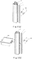
- Figure 5(a) shows an exploded three-dimensional view for a movable component, a relay module 15, a bus 1 and a pendant cabinet 16 of an embodiment of the present invention.
- Figure 5(b) shows an exploded three-dimensional view for a movable component, a relay module 15, a bus 1 and a pendant cabinet 16 of another embodiment of the present invention.
- the movable component can be in the form of handle 100.
- the movable component can comprise the handle 100 and a laminate 200.
- movable components such as an infusion rod, a display support arm, a medical guide rail and the like can also be used.
- the attachments so long as they can be adjusted at a position in lengthwise direction and can transmit digital or electrical signals, all belong to the so-called "movable component" of the present invention and fall into the protection scope of the present invention.
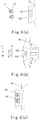
- Figure 6(a) shows the bus and cabinet of an embodiment of the present invention, in which the bus is not installed to the cabinet yet.
- Figure 6(b) shows the bus and cabinet of another embodiment of the present invention, in which the bus is not installed to the cabinet yet.
- Figure 6(c) shows the bus and cabinet of another embodiment of the present invention, in which the bus has been installed to the cabinet yet.
- the bus 1 is disposed in an inner groove 162 inside the pendant cabinet 16 or on the exterior surface thereof and extending along the lengthwise direction of the pendant cabinet, and the bus 1 comprises an insulator 18 accommodated inside the inner groove 162, and a conductor 17 enclosed inside the insulator 18.
- the pendant cabinet 16 is at least partially molded via extrusion so as to integrally form the inner groove 162.
- the inner groove 162 is substantially filled when the insulator 18 is accommodated inside the inner groove 162 and the conductor 17 is enclosed inside the insulator 18.
- the electrical interface has good reliability and insulation performance, effectively preventing the infiltration of water or other cleaning agents during the cleaning process in a hospital.
- the number of the lines of bus 1 is two, namely, the bus 1 comprises two insulators 18 accommodated inside the inner groove 162, and two conductors 17 respectively enclosed inside the two insulators 18.
- the number of the lines of the bus of the present invention is not limited to two, other numbers such as three, four.—can also be used.
- Various numbers of the lines of the bus fall into the protective scope of the present invention, so long as they can achieve the effective transmission of the power supply and instructions.
- the cross section of the conductor 17 can be substantially ⁇ shaped.
- the cross section of the conductor 17 can also be substantially in inverted Y shape.
- other cross section shapes of the conductor such as V-shape, W-shape, C-shape, or T-shape and so on, can also be used, so long as it can ensure the effective connection or contact between the relay module electrical interface (such as pin) and the bus, such variations also fall within the protection scope of the present invention.
- the inner groove 162 extends across the entire length of the pendant cabinet 16.
- the insulator 18 extends along the lengthwise direction of the pendant cabinet. Preferably, as shown in figures 5(a) and 5(b) , the insulator 18 also extends across the entire length of the pendant cabinet 16.
- conductor 17 extends along the lengthwise direction of the pendant cabinet. Preferably, the conductor 17 also extends across the entire length of the pendant cabinet 16.
- the medical pendant system of the present invention can freely adjust the position of a medical attachment (i.e., the movable component) across the entire length of the pendant cabinet, and easily and quickly realize the electrical connection and/or the mechanical connection.
- a medical attachment i.e., the movable component
- relay modules 15 may be disposed between the display module 11 and the bus 1, between the display data line module 12 and the bus, between the pulse sensor module 13 and the bus 1, as well as between the pulse diagnostic instrument module 14 and the bus 1.
- These relay modules 15 can be substantially identical to the relay module 15 located between the movable component and the bus 1 described previously, as well as the relay module 15 located between the execution component and the bus 1.
Landscapes
- Health & Medical Sciences (AREA)
- Life Sciences & Earth Sciences (AREA)
- Engineering & Computer Science (AREA)
- Architecture (AREA)
- Surgery (AREA)
- Public Health (AREA)
- Biomedical Technology (AREA)
- Heart & Thoracic Surgery (AREA)
- Medical Informatics (AREA)
- Molecular Biology (AREA)
- Physics & Mathematics (AREA)
- Animal Behavior & Ethology (AREA)
- General Health & Medical Sciences (AREA)
- Pathology (AREA)
- Veterinary Medicine (AREA)
- Biophysics (AREA)
- Cardiology (AREA)
- Civil Engineering (AREA)
- Structural Engineering (AREA)
- Physiology (AREA)
- Accommodation For Nursing Or Treatment Tables (AREA)
- Jib Cranes (AREA)
- Wind Motors (AREA)
Description
- The present application claims the priorities of Chinese patent application No.
201310242880.9 filed on June 19, 2013 201410181033.0 filed on April 30, 2014 - The present invention relates to the technical field of medical equipment, and more particularly to a medical pendant system.
- Medical pendant system is an indispensable medical equipment used in modern hospital operating room, intensive care unit and the like. The current medical pendant systems mainly employ the following technical solutions: the circuit control part is connected in a fixed position manner; the line control part is connected in one-to-one manner; the number of several control keys corresponding to the number of several loops, see
Fig. 1 ; and different main control circuits corresponding to different applications. - Disadvantages of such technical solutions are: the location adjustment is not convenient for the users; there are too many cables, the space occupancy is relatively high, and the length of the cables is fixed; there are no extended functions; the maintenance is not convenient; and there are too many main control circuit boards, leading not versatile.
- United States patent application
US 2011/118879 A1 relates to a medical supply unit, which includes a bus system for transmitting instructions of control elements to actuators. The bus system is provided with transmitters and receivers being connected to each other by a transmission system. Via the transmission system, commands of the transmitters are transmitted, which are controlled by the control elements, and the responsive receiver transfers the command to a switching instruction at an output of the responsive receiver so as to control an actuator. -
US 2009/0201632 A1 relates to a medical care unit, which provides power supply or data transmission in medical apparatuses. In particular, current consumers and data transmission apparatuses are slidable along a coupling device of the medical care unit. The medical care unit includes an oblong support that includes the coupling device, which extend along the support and include at least two electrically insulated bus bars continuously extending in the coupling device. At least two bus bars are formed as power supply bus bars, at least one bus bar is formed as a data transmission bus bar, the coupling device as a hollow bar is formed with an opening along its longitudinal direction, and the power supply bus bars and the data transmission bus bars are arranged inside the hollow bar. - The purpose of the present invention is to overcome the above-mentioned disadvantages of the existing medical pendant systems, in the vertical direction the medical pendant system can be adjusted steplessly without having to alter the lengths of the cables; the number of cable cores is reduced, circuit design is optimized, installation and maintenance are easy, functional integration and extension are convenient, and reliability is improved.
- The above purpose of the present invention is achieved by a medical pendant system comprising the features of
independent claim 1. The medical pendant system comprises a movable component, an execution component and a bus; the movable component comprises a key control module; the key control module comprises a braking system control key and a pendant lifting/lowering control key; the execution component comprises an output control part; the output control part is connected respectively with a bus power supply, a pendant motor, and a braking system; the movable component and the execution component are connected respectively to the bus; the bus is used for transmitting power supply, and also used for transmitting instructions from the movable component to the execution component. - According to the technical solution described above, the medical pendant system of the present invention can have the following beneficial technical effects: in the vertical direction the medical pendant system can be adjusted steplessly without having to alter the lengths of the cables; the number of cable cores is reduced, circuit design is optimized, installation and maintenance are easy, functional integration and extension are convenient, and reliability is improved.
- The medical pendant system further comprises a relay module located between the movable component and the bus, and a relay module located between the execution component and the bus.
- According to the technical solution described above, the medical pendant system of the present invention can have the following beneficial technical effects: the electrical connection and the mechanical connection among the movable component, the execution component and the bus can be achieved, various modules having control function or data transfer function are connected into the bus, and the individual modules can be ensured to be steplessly adjusted in lengthwise direction.
- Preferably, the bus is disposed in an inner groove inside the pendent cabinet or on the exterior surface thereof and extending along the lengthwise direction of the pendant cabinet, and the bus comprises an insulator accommodated inside the inner groove, and a conductor enclosed inside the insulator.
- According to the technical solution described above, the medical pendant system of the present invention can have the following beneficial technical effects: it can possess a standardized interface, without complicatedly connecting electrical cables, disassembly is easy, and the free adjustment of the position of a medical attachment is allowed.
- Preferably, the inner groove is substantially filled when the insulator is accommodated inside the inner groove and the conductor is enclosed inside the insulator.
- According to the technical solution described above, the medical pendant system of the present invention can have the following beneficial technical effects: the electrical interface has good reliability and insulation performance, effectively preventing the infiltration of water or other cleaning agents during the cleaning process in a hospital.
- Preferably, the number of lines of the bus is two, namely, the bus comprises two insulators accommodated inside the inner groove and two conductors respectively enclosed inside the two insulators.
- According to the technical solution described above, the medical pendant system of the present invention can have the following beneficial technical effects: by means of the appropriate number and settings of the above insulators and conductors, a simple and reliable connection between the pin of the relay module and the conductor inside the cabinet can be achieved.
- Preferably, the cross section of the conductor is substantially Y-shaped, Ω-shaped, V-shaped, W-shaped, C-shaped, or T-shaped.
- According to the technical solution described above, the medical pendant system of the present invention can have the following beneficial technical effects: by means of the appropriate shape of the above conductor, a simpler and reliable connection between the pin of the relay module and the conductor inside the cabinet can be achieved.
- Preferably, the output control part is further connected with a pendant protecting sensor.
According to the technical solution described above, the medical pendant system of the present invention can have the following beneficial technical effects: an effective connection between the pendant and other medical devices can be ensured before lifting and lowering by the motor, thus working normally. - Preferably, the output control part is further connected with a height limiting unit for limiting the lifting and lowering range of the pendant.
- According to the technical solution described above, the medical pendant system of the present invention can have the following beneficial technical effects: providing the limitation for the range for lifting and lowering the pendant system.
- Preferably, the output control part is further connected with a pendant motor power supply.
- According to the technical solution described above, the medical pendant system of the present invention can have the following beneficial technical effects: the pendant motor power supply can be provided to supply power to the pendant motor.
- Preferably, the movable component further comprises an environmental lamp module.
- According to the technical solution described above, the medical pendant system of the present invention can have the following beneficial technical effects: it can conveniently provide environmental illumination.
- Preferably, the movable component further comprises a display module, the execution component further comprises a display data line module.
- According to the technical solution described above, the medical pendant system of the present invention can have the following beneficial technical effects: a display can be conveniently connected.
- Preferably, the movable component further comprises a pulse sensor module, the execution component further comprises a pulse diagnostic instrument module.
- According to the technical solution described above, the medical pendant system of the present invention can have the following beneficial technical effects: a pulse sensor and a pulse diagnostic instrument can be conveniently connected.
- Preferably, the key control module further comprises an input conversion interface.
- According to the technical solution described above, the medical pendant system of the present invention can have the following beneficial technical effects: the conversion of key instructions into instructions which are recognizable by a bus transmission can be realized.
- The above purpose of the present invention is further achieved by a medical pendant system, wherein the medical pendant system comprises a movable component, an execution component and a bus; the movable component comprises a key control module; the key control module comprises a braking system control key and a pendant lifting/lowering control key; the execution component comprises an output control part; the output control part is connected respectively with a bus power supply, a pendant motor, and a braking system; the movable component and the execution component are connected respectively to the bus; the medical pendant system further comprises a relay module located between the movable component and the bus, and a relay module located between the execution component and the bus, the two relay modules are substantially identical and both of them comprise a relay module mechanical interface and a relay module electrical interface for respectively connecting to a cabinet mechanical interface and a cabinet electrical interface disposed on the pendant cabinet.
- According to the technical solution described above, the medical pendant system of the present invention can have the following beneficial technical effects: in the vertical direction the medical pendant system can be adjusted steplessly without having to alter the lengths of the cables; the number of cable cores is reduced, circuit design is optimized, installation and maintenance are easy, functional integration and extension are convenient, and reliability is improved.
- The relay module mechanical interface comprises a concave curved surface portion or a convex curved surface portion disposed on the relay module, and the cabinet mechanical interface comprises correspondingly a convex curved surface portion or a concave curved surface portion disposed on the pendant cabinet.
- According to the technical solution described above, the medical pendant system of the present invention can have the following beneficial technical effects: the mechanical connection can be effectively achieved and the connection reliability is improved; furthermore, a medical attachment is easy to be disassembled and the position of the medical attachment can be freely and steplessly adjusted.
- Preferably, the relay module electrical interface comprises a pin disposed on the relay module, and the cabinet electrical interface comprises the bus disposed on the pendant cabinet.
- According to the technical solution described above, the medical pendant system of the present invention can have the following beneficial technical effects: it can possess a standardized electrical interface, without complicatedly connecting electrical cables, disassembly is easy, and the free adjustment of the position of a medical attachment is allowed.
-
-
Figure 1 is a line diagram for the key control end of the medical pendant system of the prior art. -
Figure 2 is a line diagram for the medical pendant system of an embodiment of the present invention. -
Figure 3 is a functional extension line diagram for the medical pendant system of an embodiment of the present invention. -
Figure 4(a) is an exploded three-dimensional view for the relay module, bus and pendant cabinet of an embodiment of the present invention. -
Figure 4(b) is an exploded top view for the relay module, bus and pendant cabinet of an embodiment of the present invention. -
Figure 5(a) is an exploded three-dimensional view for the movable component, relay module, bus and pendant cabinet of an embodiment of the present invention. -
Figure 5(b) is an exploded three-dimensional view for the movable component, relay module, bus and pendant cabinet of another embodiment of the present invention. -
Figure 6(a) is a cross section for the bus and cabinet of an embodiment of the present invention, in which the bus is not installed to the cabinet yet. -
Figure 6(b) is a cross section for the bus and cabinet of another embodiment of the present invention, in which the bus is not installed to the cabinet yet. -
Figure 6(c) is a cross section for the bus and cabinet of another embodiment of the present invention, in which the bus has been installed to the cabinet. -
- 1. bus;
- 2. environmental lamp module;
- 3. key control module;
- 4. output control part;
- 5. bus power supply;
- 6. pendant protecting sensor;
- 7. pendant motor power supply;
- 8. height limiting unit;
- 9. pendant motor;
- 10. braking system;
- 11. display module;
- 12. display data line module;
- 13. pulse sensor module;
- 14. pulse diagnostic instrument module;
- 15. relay module;
- 16. pendant cabinet;
- 17. conductor;
- 18. insulator;
- 31. input conversion interface;
- 100. handle;
- 151. relay module mechanical interface;
- 152. relay module electrical interface;
- 161. cabinet mechanical interface;
- 162. inner groove;
- 200. laminate;
- K1. braking system control key;
- K2. pendant lifting/lowering control key;
- K3. pendant lifting/lowering control key;
- K4. braking system control key.
- The present invention is further described in connection with drawings and particular embodiments as follows and elaborated in more detail in the following description in order to fully understand the present invention, but it is evident that the present invention can be implemented in many other ways which are different from those described herein; generalization and deduction can be made by a skilled in the art without departing from the connotation of the invention according to practical application, and therefore the protective scope of the present invention should not be limited by the specific content of embodiments of the present invention herein.
-
Figure 2 shows a line diagram for the medical pendant system of an embodiment of the present invention. - The medical pendant system of the present invention comprises a movable component, an execution component and a
bus 1; the movable component comprises akey control module 3; thekey control module 3 comprises a braking system control keys K1 and K4 and a pendant lifting/lowering control keys K2 and K3; the execution component comprises an output control part 4; the output control part 4 is connected respectively with abus power supply 5, a pendant motor 9, and abraking system 10; the movable component and the execution component are connected respectively to thebus 1; and thebus 1 is used for transmitting power supply, and also used for transmitting instructions from the movable component to the execution component. - The present invention employs power supply carrier wave technology, utilizes two conductors as bus carrier, which in one aspect is used for transmitting the power supply, and in another aspect is used for transmitting instructions (i.e., transmitting instructions from the movable component to the execution component), thus achieving the control of the output control part 4 via the
key control module 3, and then driving the execution component by means of the output control part 4. - Preferably, the
key control module 3 of the present invention comprises a key control part and aninput conversion interface 31, wherein the two parts are designed integrally for achieving the operation of the basic functions. The key comprises the braking system control keys K1 and K4, as well as the pendant lifting/lowering control keys K2 and K3. Theinput conversion interface 31 is used for converting the key instructions into instructions which are recognizable by bus transmission. The number of thekey control module 3 in the medical pendant system is not limited to one, and more than one key control modules can be used (considering that the key control modules are likely installed on all of the different sides for the convenient spot operation). - Preferably, the output control part of the present invention can be used for achieving the conversion of the instructions on the bus into the instructions which are recognizable by the execution component, thereby ensuring that the system achieves the control action on various execution components via the bus.
- Preferably, as shown in
figure 2 , the number of the output control part is one. In this way, since power supply carrier wave technology is employed and two conductors are used as bus carrier, multiple execution components such as the pendant motor and the braking system can be controlled by only one output control part, and the control can further extend to such execution components as the pendant protecting sensor, the height limiting unit, the pendant motor power supply, or the environmental lamp module or the like. - Certainly, on the basis of the present invention, a person skilled in the art should understand that the number of the output control part of the present invention is not limited to one, other numbers such as two, three.......can also be used. Various numbers of the output control parts fall into the protective scope of the present invention, so long as the effective control of multiple execution components can be achieved.
- Preferably, as shown in
figure 2 , the medical pendant system further comprises arelay module 15 located between the movable component and thebus 1, and arelay module 15 located between the execution component and thebus 1. - Preferably, as shown in
figure 2 , the output control part 4 is further connected with a pendant protecting sensor 6. - Preferably, as shown in
figure 2 , the output control part 4 is further connected with a height limiting unit 8 for limiting the lifting and lowering range of the pendant. - Preferably, as shown in the
figure 2 , the output control part 4 is further connected with a pendant motor power supply 7. - Preferably, as shown in
figure 2 , the movable component further comprises an environmental lamp module 2. The environmental lamp module 2 can be an integrated module or a split module. - That is to say, in addition to the bus power supply, the pendant motor and the braking system, a person skilled in the art should understand, on the basis of the present invention, that the movable component can further be extended, for example, to include the pendant protecting sensor 6, the height limiting unit 8, the pendant motor power supply 7, or the environmental lamp module 2.
- The relevant modules or components which are possibly employed in the medical pendant system of present invention are presented in more details hereinafter.
- Key control module 3: the statuses (pressed or released) of the four keys in its key part are respectively represented by different software codes; when the
input conversion interface 31 receives a corresponding identification code, the identification code is converted into a bus instruction to be executed, with the identification of the code here directed against a single key; and if more than one keys are pressed at the same time, then no instruction is sent. - Relay module 15: it is used for the electrical connection and the mechanical connection, various modules having control function or data transfer function are connected into the bus, and the positions of the individual modules can be ensured to be fixed after they are moved in lengthwise direction.
- Bus 1: it is used as a carrier for transmitting instructions to the output control part, and in another aspect, for achieving the electrical connection with the power supply.
- Output control part 4: the output control part 4 will periodically scan to determine that whether there is an instruction sent from the
bus 1, the matched instructions when received are converted into control instructions so as to drive the action of the corresponding execution component. - Bus power supply 5 (alternative/direct current power supply): it is used for providing control power supply for the bus system (the medical pendant system), in one aspect used for providing power supply for the bus system, and in another aspect used for providing power for the spot environmental lamp or other units.
- Pendant protecting sensor 6: it is used for satisfying the requirements for protecting the pendant system under different applications; a set of corresponding instructions will be provided for the output control part when the pendant protecting sensor 6 senses a corresponding object; the output control part when receives the corresponding instructions will logically analyze the instructions correspondingly to produce corresponding output so as to make the pendant be capable of working normally.
- Braking system 10: the system releases the corresponding shaft brake when the key K1 or K4 is pressed; and the system lock the corresponding shaft brake when the key K1 or K4 is released.
- Pendant motor 9: it is used for driving the lifting or the lowering of the pendant. The pendant is lifted when the key K2 is pressed; and the pendant is lowered when the key K3 is pressed.
- Height limiting unit 8: it is used for providing the limitation for the lifting and lowering range of the pendant. When the highest point set for the pendant is achieved, a set of corresponding instructions will be provided for the output control part to cease the continued lifting of the pendant, and the pendant in this case can only be lowered. When the lowest point set for the pendant is achieved, a set of corresponding instructions will be provided for the output control part to cease the continued lowering of the pendant, and the pendant in this case can only be lifted.
- Pendant motor power supply 7: the pendant motor power supply 7 is disposed to supply power to the pendant motor.
Figure 3 shows a line diagram for functional extension of the medical pendant system of an embodiment of the present invention. - The bus is employed as a carrier to code, decode and convert video signals, audio signals, and pulse signals, thus achieving the connection and signal transmission of the pulse diagnostic instrument or the medical display and other extension devices.
- Preferably, as shown in
figure 3 , the movable component further comprises adisplay module 11, and the execution component further comprises a displaydata line module 12. Note that the display module described here can include a display and a conversion interface, and the display data line module described here can include a display data line and a conversion interface. - Preferably, as shown in
figure 3 , the movable component further comprises apulse sensor module 13, the execution component further comprises a pulsediagnostic instrument module 14. Note that the pulse sensor module described here can include a pulse sensor and a conversion interface, and the pulse diagnostic instrument module described here can include a diagnostic instrument and a conversion interface. -
Figure 4(a) shows an exploded three-dimensional view for arelay module 15, abus 1 and apendant cabinet 16 of an embodiment of the present invention.Figure 4(b) shows an exploded top view for arelay module 15, abus 1 and apendant cabinet 16 of an embodiment of the present invention. - As shown in
figure 4(b) , therelay module 15 comprises a relay modulemechanical interface 151 and a relay moduleelectrical interface 152 for connecting with the cabinetmechanical interface 161 and the cabinet electrical interface on thependant cabinet 16, respectively. - The relay module
electrical interface 152 can be used as the electrical interface of thebus 1 to various attachments (i.e., the movable component) which carry control or signal transmission, and can be used for connecting theinput conversion interface 31 and thebus 1, or for connecting the output conversion interface and thebus 1, thereby ensuring the medical pendant system to realize smooth electrical connection. Meanwhile, the relay modulemechanical interface 151 ensures that various attachments can be adjusted at any position in lengthwise direction. - Preferably, the
relay module 15 located between the movable component and thebus 1 is substantially identical to therelay module 15 located between the execution component and thebus 1, namely, both of them comprise a relay modulemechanical interface 151 and a relay moduleelectrical interface 152 for connecting with the cabinetmechanical interface 161 and the cabinet electrical interface on thependant cabinet 16, respectively. Here, "substantially identical" refers to the both therelay modules 15 comprise the relay modulemechanical interface 151 and the relay moduleelectrical interface 152, but they can comprise other different additional structures or parts. - As shown in
figure 4(b) , the relay modulemechanical interface 151 comprises a convex curved surface portion disposed on therelay module 15, and the cabinetmechanical interface 161 comprises a corresponding concave curved surface portion disposed on thependant cabinet 16. Although the examples given above only describe the circumstance of the matching of the concave curved surface portion of the pendant cabinet to the convex curved surface portion of the relay module mechanical interface, a person skilled in the art should understand, on the basis of the present invention, that the form of matching of the convex curved surface portion of the pendant cabinet to the concave curved surface portion of the relay module mechanical interface can also be used. Such variation also falls into the protection scope of the present invention. - Preferably, as shown in
figure 4(b) , the relay moduleelectrical interface 152 comprises a pin disposed on therelay module 15, and the cabinet electrical interface comprises abus 1 disposed on thependant cabinet 16. - Certainly, a person skilled in the art should understand, on the basis of the present invention, that the relay module electrical interface of the present invention is not limited to a pin, and other forms such as tab, wiring, quick connector, welding, and wireless connection and the like can also be used. Various forms of relay module electrical interfaces fall into the protection scope of the present invention so long as they can realize the effective electrical connection of the relay module and the pendant cabinet.
-
Figure 5(a) shows an exploded three-dimensional view for a movable component, arelay module 15, abus 1 and apendant cabinet 16 of an embodiment of the present invention.Figure 5(b) shows an exploded three-dimensional view for a movable component, arelay module 15, abus 1 and apendant cabinet 16 of another embodiment of the present invention. - As shown in
figure 5(a) , the movable component can be in the form ofhandle 100. As shown infigure 5(b) , the movable component can comprise thehandle 100 and alaminate 200. Certainly, a person skilled in the art should understand, on the basis of the present invention, that other forms of movable components, such as an infusion rod, a display support arm, a medical guide rail and the like can also be used. The attachments, so long as they can be adjusted at a position in lengthwise direction and can transmit digital or electrical signals, all belong to the so-called "movable component" of the present invention and fall into the protection scope of the present invention. -
Figure 6(a) shows the bus and cabinet of an embodiment of the present invention, in which the bus is not installed to the cabinet yet.Figure 6(b) shows the bus and cabinet of another embodiment of the present invention, in which the bus is not installed to the cabinet yet.Figure 6(c) shows the bus and cabinet of another embodiment of the present invention, in which the bus has been installed to the cabinet yet. - Preferably, as shown in
figures 6(a)-6(c) , thebus 1 is disposed in aninner groove 162 inside thependant cabinet 16 or on the exterior surface thereof and extending along the lengthwise direction of the pendant cabinet, and thebus 1 comprises aninsulator 18 accommodated inside theinner groove 162, and aconductor 17 enclosed inside theinsulator 18. - Preferably, the
pendant cabinet 16 is at least partially molded via extrusion so as to integrally form theinner groove 162. - Preferably, as shown in
figures 6(a)-6(c) , theinner groove 162 is substantially filled when theinsulator 18 is accommodated inside theinner groove 162 and theconductor 17 is enclosed inside theinsulator 18. - In this way, the electrical interface has good reliability and insulation performance, effectively preventing the infiltration of water or other cleaning agents during the cleaning process in a hospital.
- Preferably, as shown in
figures 6(a)-6(c) , the number of the lines ofbus 1 is two, namely, thebus 1 comprises twoinsulators 18 accommodated inside theinner groove 162, and twoconductors 17 respectively enclosed inside the twoinsulators 18. - Certainly, on the basis of the present invention, a person skilled in the art should understand that the number of the lines of the bus of the present invention is not limited to two, other numbers such as three, four.......can also be used. Various numbers of the lines of the bus fall into the protective scope of the present invention, so long as they can achieve the effective transmission of the power supply and instructions.
- Preferably, as shown in
figures 6(a) and 6(c) , the cross section of theconductor 17 can be substantially Ω shaped. As shown infigure 6(b) , the cross section of theconductor 17 can also be substantially in inverted Y shape. Certainly, a person skilled in the art should understand, on the basis of the present invention, that other cross section shapes of the conductor, such as V-shape, W-shape, C-shape, or T-shape and so on, can also be used, so long as it can ensure the effective connection or contact between the relay module electrical interface (such as pin) and the bus, such variations also fall within the protection scope of the present invention. - In this way, by means of the appropriate settings of the shape and number of the above insulators and conductors, the simple and reliable connection between the pin (or a plug) of the relay module and the conductors inside the pendant cabinet can be achieved.
- Preferably, as shown in
figures 5(a) and 5(b) , theinner groove 162 extends across the entire length of thependant cabinet 16. - Preferably, as shown in
figures 5(a) and 5(b) , theinsulator 18 extends along the lengthwise direction of the pendant cabinet. Preferably, as shown infigures 5(a) and 5(b) , theinsulator 18 also extends across the entire length of thependant cabinet 16. - Preferably,
conductor 17 extends along the lengthwise direction of the pendant cabinet. Preferably, theconductor 17 also extends across the entire length of thependant cabinet 16. - In this way, the medical pendant system of the present invention can freely adjust the position of a medical attachment (i.e., the movable component) across the entire length of the pendant cabinet, and easily and quickly realize the electrical connection and/or the mechanical connection.
- Preferably, as shown in
figure 3 , when an extension function is implemented,relay modules 15 may be disposed between thedisplay module 11 and thebus 1, between the displaydata line module 12 and the bus, between thepulse sensor module 13 and thebus 1, as well as between the pulsediagnostic instrument module 14 and thebus 1. Theserelay modules 15 can be substantially identical to therelay module 15 located between the movable component and thebus 1 described previously, as well as therelay module 15 located between the execution component and thebus 1. - The present invention has been exemplarily described above in connection with the figures, although the specific implementations of the present invention are not limited to the above embodiments. Various modifications or variations can be made by a person skilled in the art on the premise of without departing from the technical concept of the present invention, and such modifications or variations of course fall within the protection scope of the present invention as defined by the appended claims.
Claims (13)
- A medical pendant system comprising a movable component, an execution component and a bus (1); the movable component comprises a key control module (3); the key control module (3) comprises a braking system control key (K1, K4) and a pendant lifting/lowering control key (K2, K3); the execution component comprises an output control part (4); the output control part (4) is connected respectively with a bus power supply (5), a pendant motor (9), and a braking system (10); the movable component and the execution component are connected respectively to the bus (1); the bus (1) is used for transmitting power supply, and also used for transmitting instructions from the movable component to the execution component,
wherein the medical pendant system further comprises a relay module (15) located between the movable component and the bus (1), and a relay module (15) located between the execution component and the bus (1), wherein the two relay modules (15) are substantially identical and each of them comprises a relay module mechanical interface (151) and a relay module electrical interface (152) for respectively connecting to a cabinet mechanical interface (161) and a cabinet electrical interface disposed on the pendant cabinet (16), characterized in that the relay module mechanical interface (151) comprises a concave curved surface portion or a convex curved surface portion disposed on the relay module (15), and the cabinet mechanical interface (161) comprises correspondingly a matching convex curved surface portion or a matching concave curved surface portion disposed on the pendant cabinet (16). - The medical pendant system of claim 1, wherein the bus (1) is disposed in an inner groove (162) inside the pendant cabinet (16) or on the exterior surface thereof and extending along the lengthwise direction of the pendant cabinet (16), and the bus (1) comprises an insulator (18) accommodated inside the inner groove (162), and a conductor (17) enclosed inside the insulator (18);
- The medical pendant system of claim 2, wherein the inner groove (162) is filled when the insulator (18) is accommodated inside the inner groove (162) and the conductor (17) is enclosed inside the insulator (18).
- The medical pendant system of claim 1, wherein the number of lines of the bus (1) is two, namely, the bus (1) comprises two insulators (18) accommodated inside the inner groove (162) and two conductors (17) respectively enclosed inside the two insulators (18).
- The medical pendant system of claim 4, wherein the cross section of the conductor (17) is substantially Y-shaped, Ω-shaped, V-shaped, W-shaped, C-shaped, or T-shaped.
- The medical pendant system of claim 1, wherein the output control part (4) is further connected with a pendant protecting sensor (6).
- The medical pendant system of claim 1, wherein the output control part (4) is further connected with a height limiting unit (8) for limiting the lifting and lowering range of the pendant.
- The medical pendant system of claim 1, wherein the output control part (4) is further connected with a pendant motor power supply (7).
- The medical pendant system of claim 1, wherein the movable component further comprises an environmental lamp module.
- The medical pendant system of claim 1, wherein the movable component further comprises a display module (11), and the execution component further comprises a display data line module (12).
- The medical pendant system of claim 1, wherein the movable component further comprises a pulse sensor module, and the execution component further comprises a pulse diagnostic instrument module.
- The medical pendant system of claim 1, wherein the key control module (3) further comprises an input conversion interface (31).
- The medical pendant system of claim 1, wherein the relay module electrical interface (152) comprises a pin disposed on the relay module (15), and the cabinet electrical interface comprises the bus (1) disposed on the pendant cabinet (16).
Applications Claiming Priority (3)
| Application Number | Priority Date | Filing Date | Title |
|---|---|---|---|
| CN2013102428809A CN103294070A (en) | 2013-06-19 | 2013-06-19 | Tower crane control system |
| CN201410181033 | 2014-04-30 | ||
| PCT/CN2014/079571 WO2014201960A1 (en) | 2013-06-19 | 2014-06-10 | Medical pendant system |
Publications (3)
| Publication Number | Publication Date |
|---|---|
| EP3011941A1 EP3011941A1 (en) | 2016-04-27 |
| EP3011941A4 EP3011941A4 (en) | 2017-02-22 |
| EP3011941B1 true EP3011941B1 (en) | 2019-05-15 |
Family
ID=51506952
Family Applications (1)
| Application Number | Title | Priority Date | Filing Date |
|---|---|---|---|
| EP14813742.5A Active EP3011941B1 (en) | 2013-06-19 | 2014-06-10 | Medical pendant system |
Country Status (6)
| Country | Link |
|---|---|
| US (1) | US10092198B2 (en) |
| EP (1) | EP3011941B1 (en) |
| JP (1) | JP6515092B2 (en) |
| CN (2) | CN104055576B (en) |
| SG (1) | SG11201510401VA (en) |
| WO (1) | WO2014201960A1 (en) |
Families Citing this family (6)
| Publication number | Priority date | Publication date | Assignee | Title |
|---|---|---|---|---|
| CN104055576B (en) * | 2013-06-19 | 2016-06-22 | 迈柯唯医疗设备(苏州)有限公司 | Medical hoist tower system |
| CN103919615B (en) * | 2014-04-30 | 2017-01-25 | 迈柯唯医疗设备(苏州)有限公司 | Medical crane box and stand columns for medical crane box |
| CN104257429A (en) * | 2014-09-30 | 2015-01-07 | 迈柯唯医疗设备(苏州)有限公司 | Touch type sensing handle for medical tower crane |
| CN104382652B (en) * | 2014-12-03 | 2017-01-25 | 迈柯唯医疗设备(苏州)有限公司 | Medical tower crane system |
| CN110750108A (en) * | 2019-09-03 | 2020-02-04 | 浙江捷昌线性驱动科技股份有限公司 | Multi-lifting platform control system |
| CN112569000A (en) * | 2020-12-04 | 2021-03-30 | 青岛卓森纳生物工程有限公司 | Gastroenterology is with inspection auxiliary frame convenient to adjust |
Citations (2)
| Publication number | Priority date | Publication date | Assignee | Title |
|---|---|---|---|---|
| EP1424755A1 (en) * | 2001-09-05 | 2004-06-02 | Mitsubishi Denki Kabushiki Kaisha | Conductor connection structure |
| US20090201632A1 (en) * | 2007-11-08 | 2009-08-13 | Trumpf Medizin Systeme Gmbh + Co. Kg | Medical care unit |
Family Cites Families (19)
| Publication number | Priority date | Publication date | Assignee | Title |
|---|---|---|---|---|
| JPS6322088U (en) * | 1986-07-28 | 1988-02-13 | ||
| JPH04131886U (en) * | 1991-05-22 | 1992-12-04 | 平河ヒユ−テツク株式会社 | Electrical indicator connection device |
| DE4239625C1 (en) | 1992-11-26 | 1993-08-05 | Fresenius Ag, 6380 Bad Homburg, De | Medical transfusion equipment connecting column - forms connection with data exchange equipment and has two conductors secured by clamp with jaws and electrical contacts |
| US7073765B2 (en) | 2002-11-13 | 2006-07-11 | Hill-Rom Services, Inc. | Apparatus for carrying medical equipment |
| US7379790B2 (en) * | 2004-05-04 | 2008-05-27 | Intuitive Surgical, Inc. | Tool memory-based software upgrades for robotic surgery |
| US7884735B2 (en) | 2005-02-11 | 2011-02-08 | Hill-Rom Services, Inc. | Transferable patient care equipment support |
| US7770860B1 (en) * | 2005-11-10 | 2010-08-10 | Modular Services Company | Medical service system on articulating arm with electromagnetic brakes |
| DE202006015827U1 (en) * | 2006-10-16 | 2006-12-07 | Knürr AG | Power-bus bar system for casings and cupboards in information technology has a basic structure to conduct power and a module for distributing and supplying power |
| JP4816544B2 (en) * | 2007-03-30 | 2011-11-16 | パナソニック電工株式会社 | Wiring system |
| DE102009009549A1 (en) | 2009-02-19 | 2010-09-02 | Olympus Winter & Ibe Gmbh | Method for positioning medical device on carrier device, involves providing target position of medical device, where relative position of medical device, is determined for target position, and positioning support signal is optical signal |
| EP2322130B1 (en) * | 2009-11-16 | 2013-01-16 | TRUMPF Medizin Systeme GmbH + Co. KG | Medical supply unit |
| DE102010051633A1 (en) * | 2010-11-17 | 2012-05-24 | Ondal Medical Systems Gmbh | Carrying system with operator assistance |
| CN102198034A (en) * | 2011-05-04 | 2011-09-28 | 上海龙奕实业有限公司 | Medical pendant comprising central control system |
| JP6373758B2 (en) * | 2011-11-16 | 2018-08-15 | ボルケーノ コーポレイション | Medical measurement system and method |
| CN202515780U (en) * | 2012-02-28 | 2012-11-07 | 东莞康华众邦医疗科技发展有限公司 | Pendant with electronically monitored boom levelness |
| CN203299653U (en) * | 2013-06-19 | 2013-11-20 | 迈柯唯医疗设备(苏州)有限公司 | Tower crane control system |
| CN103294070A (en) * | 2013-06-19 | 2013-09-11 | 迈柯唯医疗设备(苏州)有限公司 | Tower crane control system |
| CN104055576B (en) * | 2013-06-19 | 2016-06-22 | 迈柯唯医疗设备(苏州)有限公司 | Medical hoist tower system |
| CN103591425B (en) * | 2013-11-15 | 2015-06-03 | 迈柯唯医疗设备(苏州)有限公司 | Movable type accessory fixing device applied to medical crane |
-
2014
- 2014-05-23 CN CN201410222010.XA patent/CN104055576B/en active Active
- 2014-05-23 CN CN201420268702.3U patent/CN203829052U/en not_active Expired - Lifetime
- 2014-06-10 SG SG11201510401VA patent/SG11201510401VA/en unknown
- 2014-06-10 US US14/899,777 patent/US10092198B2/en active Active
- 2014-06-10 WO PCT/CN2014/079571 patent/WO2014201960A1/en not_active Ceased
- 2014-06-10 EP EP14813742.5A patent/EP3011941B1/en active Active
- 2014-06-10 JP JP2016520257A patent/JP6515092B2/en active Active
Patent Citations (2)
| Publication number | Priority date | Publication date | Assignee | Title |
|---|---|---|---|---|
| EP1424755A1 (en) * | 2001-09-05 | 2004-06-02 | Mitsubishi Denki Kabushiki Kaisha | Conductor connection structure |
| US20090201632A1 (en) * | 2007-11-08 | 2009-08-13 | Trumpf Medizin Systeme Gmbh + Co. Kg | Medical care unit |
Also Published As
| Publication number | Publication date |
|---|---|
| CN203829052U (en) | 2014-09-17 |
| EP3011941A1 (en) | 2016-04-27 |
| CN104055576A (en) | 2014-09-24 |
| WO2014201960A1 (en) | 2014-12-24 |
| SG11201510401VA (en) | 2016-01-28 |
| CN104055576B (en) | 2016-06-22 |
| US10092198B2 (en) | 2018-10-09 |
| EP3011941A4 (en) | 2017-02-22 |
| JP6515092B2 (en) | 2019-05-15 |
| JP2016527930A (en) | 2016-09-15 |
| US20160143550A1 (en) | 2016-05-26 |
Similar Documents
| Publication | Publication Date | Title |
|---|---|---|
| US10092198B2 (en) | Medical pendant system | |
| RU2547856C2 (en) | Spark-proof connecting block with network interface, respective spark-proof device and network interface | |
| US9385521B2 (en) | Communication device for an electrical panel having a switch device | |
| CN105109906B (en) | A kind of belt conveyor safety system | |
| EP2840052B1 (en) | Remote monitoring system for lifts of various types | |
| US6752657B2 (en) | Cable and connector system for optical and electrical signals | |
| EP3138528B1 (en) | Medical pendant box body and post used for medical pendant box body | |
| CN222167494U (en) | Safety operating device for remote emergency stop | |
| KR101637318B1 (en) | Two way console system in stage setting and uniting interface used in it | |
| CN102647459A (en) | Unified remote control device for internet of thing terminal equipment | |
| CN202997102U (en) | A controllable electronic connector | |
| CN104144003A (en) | Power network bridge technology adopting GPON tail fiber access | |
| CN215645347U (en) | Multi-joint integrated cable and multifunctional bed | |
| EP0313320A3 (en) | Safety apparatus for electrical power supply cables | |
| CN202586968U (en) | Anti-interference transmission system of remote control signals of power grid | |
| US20070115136A1 (en) | Contact signal transmission and reception apparatus | |
| KR100990996B1 (en) | Field connection structure of substation | |
| CN207491120U (en) | A video signal transmission system inside an elevator car | |
| JP6299351B2 (en) | Gate drive circuit for power converter | |
| JP6419516B2 (en) | Communication cable and communication system | |
| CN107065609A (en) | The control system and control method of a kind of switch | |
| CN207369030U (en) | Wireless telecommunication system between control device | |
| KR970002718A (en) | Multi-point transceiver | |
| CN207053796U (en) | A kind of construction site covers electronic box with WIFI | |
| CN106828199B (en) | Cable anti-interference system for electrified railway section |
Legal Events
| Date | Code | Title | Description |
|---|---|---|---|
| PUAI | Public reference made under article 153(3) epc to a published international application that has entered the european phase |
Free format text: ORIGINAL CODE: 0009012 |
|
| 17P | Request for examination filed |
Effective date: 20160105 |
|
| AK | Designated contracting states |
Kind code of ref document: A1 Designated state(s): AL AT BE BG CH CY CZ DE DK EE ES FI FR GB GR HR HU IE IS IT LI LT LU LV MC MK MT NL NO PL PT RO RS SE SI SK SM TR |
|
| AX | Request for extension of the european patent |
Extension state: BA ME |
|
| DAX | Request for extension of the european patent (deleted) | ||
| A4 | Supplementary search report drawn up and despatched |
Effective date: 20170120 |
|
| RIC1 | Information provided on ipc code assigned before grant |
Ipc: A61G 12/00 20060101AFI20170116BHEP |
|
| STAA | Information on the status of an ep patent application or granted ep patent |
Free format text: STATUS: EXAMINATION IS IN PROGRESS |
|
| 17Q | First examination report despatched |
Effective date: 20171103 |
|
| GRAP | Despatch of communication of intention to grant a patent |
Free format text: ORIGINAL CODE: EPIDOSNIGR1 |
|
| STAA | Information on the status of an ep patent application or granted ep patent |
Free format text: STATUS: GRANT OF PATENT IS INTENDED |
|
| INTG | Intention to grant announced |
Effective date: 20181210 |
|
| GRAS | Grant fee paid |
Free format text: ORIGINAL CODE: EPIDOSNIGR3 |
|
| GRAA | (expected) grant |
Free format text: ORIGINAL CODE: 0009210 |
|
| STAA | Information on the status of an ep patent application or granted ep patent |
Free format text: STATUS: THE PATENT HAS BEEN GRANTED |
|
| AK | Designated contracting states |
Kind code of ref document: B1 Designated state(s): AL AT BE BG CH CY CZ DE DK EE ES FI FR GB GR HR HU IE IS IT LI LT LU LV MC MK MT NL NO PL PT RO RS SE SI SK SM TR |
|
| REG | Reference to a national code |
Ref country code: CH Ref legal event code: EP |
|
| REG | Reference to a national code |
Ref country code: DE Ref legal event code: R096 Ref document number: 602014046919 Country of ref document: DE |
|
| REG | Reference to a national code |
Ref country code: IE Ref legal event code: FG4D |
|
| REG | Reference to a national code |
Ref country code: NL Ref legal event code: MP Effective date: 20190515 |
|
| REG | Reference to a national code |
Ref country code: LT Ref legal event code: MG4D |
|
| PG25 | Lapsed in a contracting state [announced via postgrant information from national office to epo] |
Ref country code: AL Free format text: LAPSE BECAUSE OF FAILURE TO SUBMIT A TRANSLATION OF THE DESCRIPTION OR TO PAY THE FEE WITHIN THE PRESCRIBED TIME-LIMIT Effective date: 20190515 Ref country code: PT Free format text: LAPSE BECAUSE OF FAILURE TO SUBMIT A TRANSLATION OF THE DESCRIPTION OR TO PAY THE FEE WITHIN THE PRESCRIBED TIME-LIMIT Effective date: 20190915 Ref country code: ES Free format text: LAPSE BECAUSE OF FAILURE TO SUBMIT A TRANSLATION OF THE DESCRIPTION OR TO PAY THE FEE WITHIN THE PRESCRIBED TIME-LIMIT Effective date: 20190515 Ref country code: SE Free format text: LAPSE BECAUSE OF FAILURE TO SUBMIT A TRANSLATION OF THE DESCRIPTION OR TO PAY THE FEE WITHIN THE PRESCRIBED TIME-LIMIT Effective date: 20190515 Ref country code: NO Free format text: LAPSE BECAUSE OF FAILURE TO SUBMIT A TRANSLATION OF THE DESCRIPTION OR TO PAY THE FEE WITHIN THE PRESCRIBED TIME-LIMIT Effective date: 20190815 Ref country code: HR Free format text: LAPSE BECAUSE OF FAILURE TO SUBMIT A TRANSLATION OF THE DESCRIPTION OR TO PAY THE FEE WITHIN THE PRESCRIBED TIME-LIMIT Effective date: 20190515 Ref country code: FI Free format text: LAPSE BECAUSE OF FAILURE TO SUBMIT A TRANSLATION OF THE DESCRIPTION OR TO PAY THE FEE WITHIN THE PRESCRIBED TIME-LIMIT Effective date: 20190515 Ref country code: NL Free format text: LAPSE BECAUSE OF FAILURE TO SUBMIT A TRANSLATION OF THE DESCRIPTION OR TO PAY THE FEE WITHIN THE PRESCRIBED TIME-LIMIT Effective date: 20190515 Ref country code: LT Free format text: LAPSE BECAUSE OF FAILURE TO SUBMIT A TRANSLATION OF THE DESCRIPTION OR TO PAY THE FEE WITHIN THE PRESCRIBED TIME-LIMIT Effective date: 20190515 |
|
| PG25 | Lapsed in a contracting state [announced via postgrant information from national office to epo] |
Ref country code: LV Free format text: LAPSE BECAUSE OF FAILURE TO SUBMIT A TRANSLATION OF THE DESCRIPTION OR TO PAY THE FEE WITHIN THE PRESCRIBED TIME-LIMIT Effective date: 20190515 Ref country code: BG Free format text: LAPSE BECAUSE OF FAILURE TO SUBMIT A TRANSLATION OF THE DESCRIPTION OR TO PAY THE FEE WITHIN THE PRESCRIBED TIME-LIMIT Effective date: 20190815 Ref country code: RS Free format text: LAPSE BECAUSE OF FAILURE TO SUBMIT A TRANSLATION OF THE DESCRIPTION OR TO PAY THE FEE WITHIN THE PRESCRIBED TIME-LIMIT Effective date: 20190515 Ref country code: GR Free format text: LAPSE BECAUSE OF FAILURE TO SUBMIT A TRANSLATION OF THE DESCRIPTION OR TO PAY THE FEE WITHIN THE PRESCRIBED TIME-LIMIT Effective date: 20190816 |
|
| REG | Reference to a national code |
Ref country code: AT Ref legal event code: MK05 Ref document number: 1132578 Country of ref document: AT Kind code of ref document: T Effective date: 20190515 |
|
| PG25 | Lapsed in a contracting state [announced via postgrant information from national office to epo] |
Ref country code: DK Free format text: LAPSE BECAUSE OF FAILURE TO SUBMIT A TRANSLATION OF THE DESCRIPTION OR TO PAY THE FEE WITHIN THE PRESCRIBED TIME-LIMIT Effective date: 20190515 Ref country code: SK Free format text: LAPSE BECAUSE OF FAILURE TO SUBMIT A TRANSLATION OF THE DESCRIPTION OR TO PAY THE FEE WITHIN THE PRESCRIBED TIME-LIMIT Effective date: 20190515 Ref country code: EE Free format text: LAPSE BECAUSE OF FAILURE TO SUBMIT A TRANSLATION OF THE DESCRIPTION OR TO PAY THE FEE WITHIN THE PRESCRIBED TIME-LIMIT Effective date: 20190515 Ref country code: CZ Free format text: LAPSE BECAUSE OF FAILURE TO SUBMIT A TRANSLATION OF THE DESCRIPTION OR TO PAY THE FEE WITHIN THE PRESCRIBED TIME-LIMIT Effective date: 20190515 Ref country code: AT Free format text: LAPSE BECAUSE OF FAILURE TO SUBMIT A TRANSLATION OF THE DESCRIPTION OR TO PAY THE FEE WITHIN THE PRESCRIBED TIME-LIMIT Effective date: 20190515 Ref country code: RO Free format text: LAPSE BECAUSE OF FAILURE TO SUBMIT A TRANSLATION OF THE DESCRIPTION OR TO PAY THE FEE WITHIN THE PRESCRIBED TIME-LIMIT Effective date: 20190515 |
|
| REG | Reference to a national code |
Ref country code: CH Ref legal event code: PL |
|
| REG | Reference to a national code |
Ref country code: DE Ref legal event code: R097 Ref document number: 602014046919 Country of ref document: DE |
|
| PG25 | Lapsed in a contracting state [announced via postgrant information from national office to epo] |
Ref country code: MC Free format text: LAPSE BECAUSE OF FAILURE TO SUBMIT A TRANSLATION OF THE DESCRIPTION OR TO PAY THE FEE WITHIN THE PRESCRIBED TIME-LIMIT Effective date: 20190515 Ref country code: SM Free format text: LAPSE BECAUSE OF FAILURE TO SUBMIT A TRANSLATION OF THE DESCRIPTION OR TO PAY THE FEE WITHIN THE PRESCRIBED TIME-LIMIT Effective date: 20190515 Ref country code: IT Free format text: LAPSE BECAUSE OF FAILURE TO SUBMIT A TRANSLATION OF THE DESCRIPTION OR TO PAY THE FEE WITHIN THE PRESCRIBED TIME-LIMIT Effective date: 20190515 |
|
| PLBE | No opposition filed within time limit |
Free format text: ORIGINAL CODE: 0009261 |
|
| STAA | Information on the status of an ep patent application or granted ep patent |
Free format text: STATUS: NO OPPOSITION FILED WITHIN TIME LIMIT |
|
| REG | Reference to a national code |
Ref country code: BE Ref legal event code: MM Effective date: 20190630 |
|
| PG25 | Lapsed in a contracting state [announced via postgrant information from national office to epo] |
Ref country code: TR Free format text: LAPSE BECAUSE OF FAILURE TO SUBMIT A TRANSLATION OF THE DESCRIPTION OR TO PAY THE FEE WITHIN THE PRESCRIBED TIME-LIMIT Effective date: 20190515 |
|
| 26N | No opposition filed |
Effective date: 20200218 |
|
| PG25 | Lapsed in a contracting state [announced via postgrant information from national office to epo] |
Ref country code: IE Free format text: LAPSE BECAUSE OF NON-PAYMENT OF DUE FEES Effective date: 20190610 Ref country code: PL Free format text: LAPSE BECAUSE OF FAILURE TO SUBMIT A TRANSLATION OF THE DESCRIPTION OR TO PAY THE FEE WITHIN THE PRESCRIBED TIME-LIMIT Effective date: 20190515 |
|
| PG25 | Lapsed in a contracting state [announced via postgrant information from national office to epo] |
Ref country code: BE Free format text: LAPSE BECAUSE OF NON-PAYMENT OF DUE FEES Effective date: 20190630 Ref country code: SI Free format text: LAPSE BECAUSE OF FAILURE TO SUBMIT A TRANSLATION OF THE DESCRIPTION OR TO PAY THE FEE WITHIN THE PRESCRIBED TIME-LIMIT Effective date: 20190515 Ref country code: LU Free format text: LAPSE BECAUSE OF NON-PAYMENT OF DUE FEES Effective date: 20190610 Ref country code: LI Free format text: LAPSE BECAUSE OF NON-PAYMENT OF DUE FEES Effective date: 20190630 Ref country code: CH Free format text: LAPSE BECAUSE OF NON-PAYMENT OF DUE FEES Effective date: 20190630 |
|
| PG25 | Lapsed in a contracting state [announced via postgrant information from national office to epo] |
Ref country code: CY Free format text: LAPSE BECAUSE OF FAILURE TO SUBMIT A TRANSLATION OF THE DESCRIPTION OR TO PAY THE FEE WITHIN THE PRESCRIBED TIME-LIMIT Effective date: 20190515 |
|
| PG25 | Lapsed in a contracting state [announced via postgrant information from national office to epo] |
Ref country code: IS Free format text: LAPSE BECAUSE OF FAILURE TO SUBMIT A TRANSLATION OF THE DESCRIPTION OR TO PAY THE FEE WITHIN THE PRESCRIBED TIME-LIMIT Effective date: 20190915 |
|
| PG25 | Lapsed in a contracting state [announced via postgrant information from national office to epo] |
Ref country code: MT Free format text: LAPSE BECAUSE OF FAILURE TO SUBMIT A TRANSLATION OF THE DESCRIPTION OR TO PAY THE FEE WITHIN THE PRESCRIBED TIME-LIMIT Effective date: 20190515 Ref country code: HU Free format text: LAPSE BECAUSE OF FAILURE TO SUBMIT A TRANSLATION OF THE DESCRIPTION OR TO PAY THE FEE WITHIN THE PRESCRIBED TIME-LIMIT; INVALID AB INITIO Effective date: 20140610 |
|
| PG25 | Lapsed in a contracting state [announced via postgrant information from national office to epo] |
Ref country code: MK Free format text: LAPSE BECAUSE OF FAILURE TO SUBMIT A TRANSLATION OF THE DESCRIPTION OR TO PAY THE FEE WITHIN THE PRESCRIBED TIME-LIMIT Effective date: 20190515 |
|
| PGFP | Annual fee paid to national office [announced via postgrant information from national office to epo] |
Ref country code: GB Payment date: 20260615 Year of fee payment: 13 |
|
| PGFP | Annual fee paid to national office [announced via postgrant information from national office to epo] |
Ref country code: DE Payment date: 20260609 Year of fee payment: 13 |
|
| PGFP | Annual fee paid to national office [announced via postgrant information from national office to epo] |
Ref country code: FR Payment date: 20260629 Year of fee payment: 13 |