EP3011776B1 - Method and apparatus for performing access control in wireless communication system - Google Patents
Method and apparatus for performing access control in wireless communication system Download PDFInfo
- Publication number
- EP3011776B1 EP3011776B1 EP14813598.1A EP14813598A EP3011776B1 EP 3011776 B1 EP3011776 B1 EP 3011776B1 EP 14813598 A EP14813598 A EP 14813598A EP 3011776 B1 EP3011776 B1 EP 3011776B1
- Authority
- EP
- European Patent Office
- Prior art keywords
- access
- specific
- control parameter
- parameter
- access control
- Prior art date
- Legal status (The legal status is an assumption and is not a legal conclusion. Google has not performed a legal analysis and makes no representation as to the accuracy of the status listed.)
- Active
Links
- 238000000034 method Methods 0.000 title claims description 60
- 238000004891 communication Methods 0.000 title claims description 20
- 230000005540 biological transmission Effects 0.000 claims description 34
- 230000011664 signaling Effects 0.000 claims description 16
- 230000004044 response Effects 0.000 claims description 6
- 230000000977 initiatory effect Effects 0.000 claims 1
- 230000006870 function Effects 0.000 description 27
- 238000010586 diagram Methods 0.000 description 9
- 230000015654 memory Effects 0.000 description 9
- 238000007726 management method Methods 0.000 description 8
- 238000012546 transfer Methods 0.000 description 7
- 238000005516 engineering process Methods 0.000 description 6
- 230000008859 change Effects 0.000 description 4
- 238000010295 mobile communication Methods 0.000 description 4
- 230000006835 compression Effects 0.000 description 3
- 238000007906 compression Methods 0.000 description 3
- 238000001514 detection method Methods 0.000 description 3
- 238000005259 measurement Methods 0.000 description 3
- 230000007246 mechanism Effects 0.000 description 3
- 238000013468 resource allocation Methods 0.000 description 3
- 230000006978 adaptation Effects 0.000 description 2
- 238000004364 calculation method Methods 0.000 description 2
- 238000007689 inspection Methods 0.000 description 2
- 230000007774 longterm Effects 0.000 description 2
- 238000013507 mapping Methods 0.000 description 2
- 230000008569 process Effects 0.000 description 2
- 230000000153 supplemental effect Effects 0.000 description 2
- 230000001360 synchronised effect Effects 0.000 description 2
- 230000007704 transition Effects 0.000 description 2
- 230000004913 activation Effects 0.000 description 1
- 230000002776 aggregation Effects 0.000 description 1
- 238000004220 aggregation Methods 0.000 description 1
- 230000006399 behavior Effects 0.000 description 1
- 230000009286 beneficial effect Effects 0.000 description 1
- 230000001934 delay Effects 0.000 description 1
- 230000003111 delayed effect Effects 0.000 description 1
- 230000001419 dependent effect Effects 0.000 description 1
- 230000000694 effects Effects 0.000 description 1
- 238000001914 filtration Methods 0.000 description 1
- 238000012545 processing Methods 0.000 description 1
- 230000008054 signal transmission Effects 0.000 description 1
- 230000003068 static effect Effects 0.000 description 1
- 238000012384 transportation and delivery Methods 0.000 description 1
- 238000009827 uniform distribution Methods 0.000 description 1
Images


Classifications
-
- H—ELECTRICITY
- H04—ELECTRIC COMMUNICATION TECHNIQUE
- H04W—WIRELESS COMMUNICATION NETWORKS
- H04W74/00—Wireless channel access
- H04W74/08—Non-scheduled access, e.g. ALOHA
- H04W74/0833—Random access procedures, e.g. with 4-step access
- H04W74/0841—Random access procedures, e.g. with 4-step access with collision treatment
- H04W74/085—Random access procedures, e.g. with 4-step access with collision treatment collision avoidance
-
- H—ELECTRICITY
- H04—ELECTRIC COMMUNICATION TECHNIQUE
- H04W—WIRELESS COMMUNICATION NETWORKS
- H04W74/00—Wireless channel access
- H04W74/002—Transmission of channel access control information
-
- H—ELECTRICITY
- H04—ELECTRIC COMMUNICATION TECHNIQUE
- H04W—WIRELESS COMMUNICATION NETWORKS
- H04W48/00—Access restriction; Network selection; Access point selection
- H04W48/02—Access restriction performed under specific conditions
-
- H—ELECTRICITY
- H04—ELECTRIC COMMUNICATION TECHNIQUE
- H04W—WIRELESS COMMUNICATION NETWORKS
- H04W74/00—Wireless channel access
- H04W74/08—Non-scheduled access, e.g. ALOHA
- H04W74/0833—Random access procedures, e.g. with 4-step access
Definitions
- the present invention relates to wireless communications, and more particularly, to a method and apparatus for performing access control in a wireless communication system.
- Universal mobile telecommunications system is a 3 rd generation (3G) asynchronous mobile communication system operating in wideband code division multiple access (WCDMA) based on European systems, global system for mobile communications (GSM) and general packet radio services (GPRS).
- WCDMA wideband code division multiple access
- GSM global system for mobile communications
- GPRS general packet radio services
- LTE long-term evolution
- 3GPP 3 rd generation partnership project
- the 3GPP LTE is a technology for enabling high-speed packet communications. Many schemes have been proposed for the LTE objective including those that aim to reduce user and provider costs, improve service quality, and expand and improve coverage and system capacity.
- the 3GPP LTE requires reduced cost per bit, increased service availability, flexible use of a frequency band, a simple structure, an open interface, and adequate power consumption of a terminal as an upper-level requirement.
- SAC Application and service access control
- MMTel multimedia telephony
- MMTel multimedia telephony
- MMTel video service multimedia telephony
- the network cannot selectively prevent some mobile originating (MO) calls in congestion for UEs in a radio resource control (RRC) connected state (RRC_CONNECTED), while allowing other MO calls for UEs in RRC_CONNECTED. Accordingly, for enhancement of the ASAC, a method for performing access control in which only some applications are selectively prevented may be required.
- RRC radio resource control
- US 2013/040597 A1 discloses a system and a method that employs Extended Access Barring (EAB) when a Machine Type Communication (MTC) device performs an attempt to access an evolved Node B (eNB) in a wireless communication system are provided.
- EAB Extended Access Barring
- MTC Machine Type Communication
- eNB evolved Node B
- UE User Equipment
- an MTC device performs an attempt to access a network
- the system and method determines whether it can access the network and performs the access procedure.
- the system and method can control the operations of UE that performs an attempt to access a network, thereby preventing excessive access.
- US 2012/039171 A1 discloses a method for controlling network congestion is disclosed. A potential overload of the network is detected. An access class for which to change overload control information is selected. The overload control information is adjusted for the selected access class. The adjusted overload control information is then transmitted. The method may be performed by a base station.
- Telephone AB LM Ericsson ET AL discloses supplemental access control mechanisms such as trigger specific access control and application-specific access control. These allow a system to further restrict MTC devices from attempting system access when MTC device may attempt system access.
- NTT DOCOMO ET AL discloses Application and Service Access Control (ASAC), which is a mechanism for the operator to allow/prevent new access attempts from particular, operator-identified applications, MMTEL voice service and MMTEL video service, in the UE whilst it is in idle mode.
- the network can prevent/mitigate overload of the access network and/or the core network.
- the present invention provides a method and user equipment for performing access control in a wireless communication system.
- the network can selectively prevent some mobile originating (MO) calls in congestion for UEs, while allowing other MO calls for UEs.
- MO mobile originating
- CDMA code division multiple access
- FDMA frequency division multiple access
- TDMA time division multiple access
- OFDMA orthogonal frequency division multiple access
- SC-FDMA single carrier frequency division multiple access
- the CDMA can be implemented with a radio technology such as universal terrestrial radio access (UTRA) or CDMA-2000.
- UTRA universal terrestrial radio access
- the TDMA can be implemented with a radio technology such as global system for mobile communications (GSM)/general packet ratio service (GPRS)/enhanced data rate for GSM evolution (EDGE).
- GSM global system for mobile communications
- GPRS general packet ratio service
- EDGE enhanced data rate for GSM evolution
- the OFDMA can be implemented with a radio technology such as institute of electrical and electronics engineers (IEEE) 802.11 (Wi-Fi), IEEE 802.16 (WiMAX), IEEE 802-20, evolved UTRA (E-UTRA), etc.
- IEEE 802.16m is an evolution of IEEE 802.16e, and provides backward compatibility with an IEEE 802.16-based system.
- the UTRA is a part of a universal mobile telecommunication system (UMTS).
- 3rd generation partnership project (3GPP) long term evolution (LTE) is a part of an evolved UMTS (E-UMTS) using the E-UTRA.
- 3GPP LTE uses the OFDMA in downlink and uses the SC-FDMA in uplink.
- LTE-advance (LTE-A) is an evolution of the 3GPP LTE.
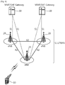
- FIG. 1 shows LTE system architecture.
- the communication network is widely deployed to provide a variety of communication services such as voice over internet protocol (VoIP) through IMS and packet data.
- VoIP voice over internet protocol
- the LTE system architecture includes one or more user equipment (UE; 10), an evolved-UMTS terrestrial radio access network (E-UTRAN) and an evolved packet core (EPC).
- the UE 10 refers to a communication equipment carried by a user.
- the UE 10 may be fixed or mobile, and may be referred to as another terminology, such as a mobile station (MS), a user terminal (UT), a subscriber station (SS), a wireless device, etc.
- MS mobile station
- UT user terminal
- SS subscriber station
- wireless device etc.
- the E-UTRAN includes one or more evolved node-B (eNB) 20, and a plurality of UEs may be located in one cell.
- the eNB 20 provides an end point of a control plane and a user plane to the UE 10.
- the eNB 20 is generally a fixed station that communicates with the UE 10 and may be referred to as another terminology, such as a base station (BS), a base transceiver system (BTS), an access point, etc.
- BS base station
- BTS base transceiver system
- One eNB 20 may be deployed per cell.
- a single cell is configured to have one of bandwidths selected from 1.25, 2.5, 5, 10, and 20 MHz, etc., and provides downlink or uplink transmission services to several UEs. In this case, different cells can be configured to provide different bandwidths.
- a downlink (DL) denotes communication from the eNB 20 to the UE
- an uplink (UL) denotes communication from the UE 10 to the eNB 20.
- a transmitter may be a part of the eNB 20, and a receiver may be a part of the UE 10.
- the transmitter may be a part of the UE 10, and the receiver may be a part of the eNB 20.
- the EPC includes a mobility management entity (MME) which is in charge of control plane functions, and a system architecture evolution (SAE) gateway (S-GW) which is in charge of user plane functions.
- MME mobility management entity
- SAE system architecture evolution gateway
- S-GW system architecture evolution gateway
- the MME/S-GW 30 may be positioned at the end of the network and connected to an external network.
- the MME has UE access information or UE capability information, and such information may be primarily used in UE mobility management.
- the S-GW is a gateway of which an endpoint is an E-UTRAN.
- the MME/S-GW 30 provides an end point of a session and mobility management function for the UE 10.
- the EPC may further include a packet data network (PDN) gateway (PDN-GW).
- PDN-GW is a gateway of which an endpoint is a PDN.
- the MME provides various functions including non-access stratum (NAS) signaling to eNBs 20, NAS signaling security, access stratum (AS) security control, Inter core network (CN) node signaling for mobility between 3GPP access networks, idle mode UE reachability (including control and execution of paging retransmission), tracking area list management (for UE in idle and active mode), P-GW and S-GW selection, MME selection for handovers with MME change, serving GPRS support node (SGSN) selection for handovers to 2G or 3G 3GPP access networks, roaming, authentication, bearer management functions including dedicated bearer establishment, support for public warning system (PWS) (which includes earthquake and tsunami warning system (ETWS) and commercial mobile alert system (CMAS)) message transmission.
- PWS public warning system
- ETWS earthquake and tsunami warning system
- CMAS commercial mobile alert system
- the S-GW host provides assorted functions including per-user based packet filtering (by e.g., deep packet inspection), lawful interception, UE Internet protocol (IP) address allocation, transport level packet marking in the DL, UL and DL service level charging, gating and rate enforcement, DL rate enforcement based on APN-AMBR.
- per-user based packet filtering by e.g., deep packet inspection
- IP Internet protocol
- transport level packet marking in the DL UL and DL service level charging
- gating and rate enforcement DL rate enforcement based on APN-AMBR.
- MME/S-GW 30 will be referred to herein simply as a "gateway,” but it is understood that this entity includes both the MME and S-GW.
- Interfaces for transmitting user traffic or control traffic may be used.
- the UE 10 and the eNB 20 are connected by means of a Uu interface.
- the eNBs 20 are interconnected by means of an X2 interface. Neighboring eNBs may have a meshed network structure that has the X2 interface.
- the eNBs 20 are connected to the EPC by means of an S1 interface.
- the eNBs 20 are connected to the MME by means of an S1-MME interface, and are connected to the S-GW by means of S1-U interface.
- the S1 interface supports a many-to-many relation between the eNB 20 and the MME/S-GW.
- FIG. 2 shows a block diagram of architecture of a typical E-UTRAN and a typical EPC.
- the eNB 20 may perform functions of selection for gateway 30, routing toward the gateway 30 during a radio resource control (RRC) activation, scheduling and transmitting of paging messages, scheduling and transmitting of broadcast channel (BCH) information, dynamic allocation of resources to the UEs 10 in both UL and DL, configuration and provisioning of eNB measurements, radio bearer control, radio admission control (RAC), and connection mobility control in LTE_ACTIVE state.
- gateway 30 may perform functions of paging origination, LTE_IDLE state management, ciphering of the user plane, SAE bearer control, and ciphering and integrity protection of NAS signaling.
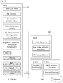
- FIG. 3 shows a block diagram of a user plane protocol stack and a control plane protocol stack of an LTE system.
- FIG. 3-(a) shows a block diagram of a user plane protocol stack of an LTE system
- FIG. 3-(b) shows a block diagram of a control plane protocol stack of an LTE system.
- Layers of a radio interface protocol between the UE and the E-UTRAN may be classified into a first layer (L1), a second layer (L2), and a third layer (L3) based on the lower three layers of the open system interconnection (OSI) model that is well-known in the communication system.
- the radio interface protocol between the UE and the E-UTRAN may be horizontally divided into a physical layer, a data link layer, and a network layer, and may be vertically divided into a control plane (C-plane) which is a protocol stack for control signal transmission and a user plane (U-plane) which is a protocol stack for data information transmission.
- C-plane control plane
- U-plane user plane
- the layers of the radio interface protocol exist in pairs at the UE and the E-UTRAN, and are in charge of data transmission of the Uu interface.
- a physical (PHY) layer belongs to the L1.
- the PHY layer provides a higher layer with an information transfer service through a physical channel.
- the PHY layer is connected to a medium access control (MAC) layer, which is a higher layer of the PHY layer, through a transport channel.
- MAC medium access control
- a physical channel is mapped to the transport channel.
- Data is transferred between the MAC layer and the PHY layer through the transport channel.
- the physical channel is modulated using an orthogonal frequency division multiplexing (OFDM) scheme, and utilizes time and frequency as a radio resource.
- OFDM orthogonal frequency division multiplexing
- the PHY layer uses several physical control channels.
- a physical downlink control channel (PDCCH) reports to a UE about resource allocation of a paging channel (PCH) and a downlink shared channel (DL-SCH), and hybrid automatic repeat request (HARQ) information related to the DL-SCH.
- the PDCCH may carry a UL grant for reporting to the UE about resource allocation of UL transmission.
- a physical control format indicator channel (PCFICH) reports the number of OFDM symbols used for PDCCHs to the UE, and is transmitted in every subframe.
- a physical hybrid ARQ indicator channel (PHICH) carries an HARQ acknowledgement (ACK)/non-acknowledgement (NACK) signal in response to UL transmission.
- ACK HARQ acknowledgement
- NACK non-acknowledgement
- a physical uplink control channel (PUCCH) carries UL control information such as HARQ ACK/NACK for DL transmission, scheduling request, and CQI.
- a physical uplink shared channel (PUSCH) carries a UL-uplink shared channel (SCH).
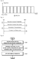
- FIG. 4 shows an example of a physical channel structure.
- a physical channel consists of a plurality of subframes in time domain and a plurality of subcarriers in frequency domain.
- One subframe consists of a plurality of symbols in the time domain.
- One subframe consists of a plurality of resource blocks (RBs).
- One RB consists of a plurality of symbols and a plurality of subcarriers.
- each subframe may use specific subcarriers of specific symbols of a corresponding subframe for a PDCCH. For example, a first symbol of the subframe may be used for the PDCCH.
- the PDCCH carries dynamic allocated resources, such as a physical resource block (PRB) and modulation and coding scheme (MCS).
- a transmission time interval (TTI) which is a unit time for data transmission may be equal to a length of one subframe. The length of one subframe may be 1 ms.
- a DL transport channel for transmitting data from the network to the UE includes a broadcast channel (BCH) for transmitting system information, a paging channel (PCH) for transmitting a paging message, a DL-SCH for transmitting user traffic or control signals, etc.
- BCH broadcast channel
- PCH paging channel
- DL-SCH DL-SCH for transmitting user traffic or control signals
- the DL-SCH supports HARQ, dynamic link adaptation by varying the modulation, coding and transmit power, and both dynamic and semi-static resource allocation.
- the DL-SCH also may enable broadcast in the entire cell and the use of beamforming.
- the system information carries one or more system information blocks. All system information blocks may be transmitted with the same periodicity. Traffic or control signals of a multimedia broadcast/multicast service (MBMS) may be transmitted through the DL-SCH or a multicast channel (MCH).
- MCH multicast channel
- a UL transport channel for transmitting data from the UE to the network includes a random access channel (RACH) for transmitting an initial control message, a UL-SCH for transmitting user traffic or control signals, etc.
- RACH random access channel
- the UL-SCH supports HARQ and dynamic link adaptation by varying the transmit power and potentially modulation and coding.
- the UL-SCH also may enable the use of beamforming.
- the RACH is normally used for initial access to a cell.
- a MAC layer belongs to the L2.
- the MAC layer provides services to a radio link control (RLC) layer, which is a higher layer of the MAC layer, via a logical channel.
- RLC radio link control
- the MAC layer provides a function of mapping multiple logical channels to multiple transport channels.
- the MAC layer also provides a function of logical channel multiplexing by mapping multiple logical channels to a single transport channel.
- a MAC sublayer provides data transfer services on logical channels.
- the logical channels are classified into control channels for transferring control plane information and traffic channels for transferring user plane information, according to a type of transmitted information. That is, a set of logical channel types is defined for different data transfer services offered by the MAC layer.
- the logical channels are located above the transport channel, and are mapped to the transport channels.
- the control channels are used for transfer of control plane information only.
- the control channels provided by the MAC layer include a broadcast control channel (BCCH), a paging control channel (PCCH), a common control channel (CCCH), a multicast control channel (MCCH) and a dedicated control channel (DCCH).
- the BCCH is a downlink channel for broadcasting system control information.
- the PCCH is a downlink channel that transfers paging information and is used when the network does not know the location cell of a UE.
- the CCCH is used by UEs having no RRC connection with the network.
- the MCCH is a point-to-multipoint downlink channel used for transmitting MBMS control information from the network to a UE.
- the DCCH is a point-to-point bi-directional channel used by UEs having an RRC connection that transmits dedicated control information between a UE and the network.
- Traffic channels are used for the transfer of user plane information only.
- the traffic channels provided by the MAC layer include a dedicated traffic channel (DTCH) and a multicast traffic channel (MTCH).
- DTCH dedicated traffic channel
- MTCH multicast traffic channel
- the DTCH is a point-to-point channel, dedicated to one UE for the transfer of user information and can exist in both uplink and downlink.
- the MTCH is a point-to-multipoint downlink channel for transmitting traffic data from the network to the UE.
- Uplink connections between logical channels and transport channels include the DCCH that can be mapped to the UL-SCH, the DTCH that can be mapped to the UL-SCH and the CCCH that can be mapped to the UL-SCH.
- Downlink connections between logical channels and transport channels include the BCCH that can be mapped to the BCH or DL-SCH, the PCCH that can be mapped to the PCH, the DCCH that can be mapped to the DL-SCH, and the DTCH that can be mapped to the DL-SCH, the MCCH that can be mapped to the MCH, and the MTCH that can be mapped to the MCH.
- An RLC layer belongs to the L2.
- the RLC layer provides a function of adjusting a size of data, so as to be suitable for a lower layer to transmit the data, by concatenating and segmenting the data received from a higher layer in a radio section.
- QoS quality of service
- the RLC layer provides three operation modes, i.e., a transparent mode (TM), an unacknowledged mode (UM), and an acknowledged mode (AM).
- TM transparent mode
- UM unacknowledged mode
- AM acknowledged mode
- the AM RLC provides a retransmission function through an automatic repeat request (ARQ) for reliable data transmission.
- a function of the RLC layer may be implemented with a functional block inside the MAC layer. In this case, the RLC layer may not exist.
- a packet data convergence protocol (PDCP) layer belongs to the L2.
- the PDCP layer provides a function of header compression function that reduces unnecessary control information such that data being transmitted by employing IP packets, such as IPv4 or IPv6, can be efficiently transmitted over a radio interface that has a relatively small bandwidth.
- the header compression increases transmission efficiency in the radio section by transmitting only necessary information in a header of the data.
- the PDCP layer provides a function of security.
- the function of security includes ciphering which prevents inspection of third parties, and integrity protection which prevents data manipulation of third parties.
- a radio resource control (RRC) layer belongs to the L3.
- the RLC layer is located at the lowest portion of the L3, and is only defined in the control plane.
- the RRC layer takes a role of controlling a radio resource between the UE and the network. For this, the UE and the network exchange an RRC message through the RRC layer.
- the RRC layer controls logical channels, transport channels, and physical channels in relation to the configuration, reconfiguration, and release of RBs.
- An RB is a logical path provided by the L1 and L2 for data delivery between the UE and the network. That is, the RB signifies a service provided the L2 for data transmission between the UE and E-UTRAN.
- the configuration of the RB implies a process for specifying a radio protocol layer and channel properties to provide a particular service and for determining respective detailed parameters and operations.
- the RB is classified into two types, i.e., a signaling RB (SRB) and a data RB (DRB).
- SRB signaling RB
- DRB data RB
- the SRB is used as a path for transmitting an RRC message in the control plane.
- the DRB is used as a path for transmitting user data in the user plane.
- the RLC and MAC layers may perform functions such as scheduling, automatic repeat request (ARQ), and hybrid automatic repeat request (HARQ).
- the PDCP layer may perform the user plane functions such as header compression, integrity protection, and ciphering.
- the RLC and MAC layers may perform the same functions for the control plane.
- the RRC layer (terminated in the eNB on the network side) may perform functions such as broadcasting, paging, RRC connection management, RB control, mobility functions, and UE measurement reporting and controlling.
- the NAS control protocol (terminated in the MME of gateway on the network side) may perform functions such as a SAE bearer management, authentication, LTE_IDLE mobility handling, paging origination in LTE_IDLE, and security control for the signaling between the gateway and UE.
- An RRC state indicates whether an RRC layer of the UE is logically connected to an RRC layer of the E-UTRAN.
- the RRC state may be divided into two different states such as an RRC connected state and an RRC idle state.
- RRC connection When an RRC connection is established between the RRC layer of the UE and the RRC layer of the E-UTRAN, the UE is in RRC_CONNECTED, and otherwise the UE is in RRC_IDLE. Since the UE in RRC_CONNECTED has the RRC connection established with the E-UTRAN, the E-UTRAN may recognize the existence of the UE in RRC_CONNECTED and may effectively control the UE.
- the UE in RRC_IDLE may not be recognized by the E-UTRAN, and a CN manages the UE in unit of a TA which is a larger area than a cell. That is, only the existence of the UE in RRC_IDLE is recognized in unit of a large area, and the UE must transition to RRC_CONNECTED to receive a typical mobile communication service such as voice or data communication.
- the UE may receive broadcasts of system information and paging information while the UE specifies a discontinuous reception (DRX) configured by NAS, and the UE has been allocated an identification (ID) which uniquely identifies the UE in a tracking area and may perform public land mobile network (PLMN) selection and cell re-selection. Also, in RRC_IDLE state, no RRC context is stored in the eNB.
- DRX discontinuous reception
- PLMN public land mobile network
- the UE In RRC_CONNECTED state, the UE has an E-UTRAN RRC connection and a context in the E-UTRAN, such that transmitting and/or receiving data to/from the eNB becomes possible. Also, the UE can report channel quality information and feedback information to the eNB.
- the E-UTRAN knows the cell to which the UE belongs. Therefore, the network can transmit and/or receive data to/from UE, the network can control mobility (handover and inter-radio access technologies (RAT) cell change order to GSM EDGE radio access network (GERAN) with network assisted cell change (NACC)) of the UE, and the network can perform cell measurements for a neighboring cell.
- RAT inter-radio access technologies
- GERAN GSM EDGE radio access network
- NACC network assisted cell change
- the UE specifies the paging DRX cycle. Specifically, the UE monitors a paging signal at a specific paging occasion of every UE specific paging DRX cycle.
- the paging occasion is a time interval during which a paging signal is transmitted.
- the UE has its own paging occasion.
- a paging message is transmitted over all cells belonging to the same tracking area. If the UE moves from one TA to another TA, the UE will send a tracking area update (TAU) message to the network to update its location.
- TAU tracking area update
- the UE When the user initially powers on the UE, the UE first searches for a proper cell and then remains in RRC_IDLE in the cell. When there is a need to establish an RRC connection, the UE which remains in RRC_IDLE establishes the RRC connection with the RRC of the E-UTRAN through an RRC connection procedure and then may transition to RRC_CONNECTED. The UE which remains in RRC_IDLE may need to establish the RRC connection with the E-UTRAN when uplink data transmission is necessary due to a user's call attempt or the like or when there is a need to transmit a response message upon receiving a paging message from the E-UTRAN.
- the message When a UE wishes to access the network and determines a message to be transmitted, the message may be linked to a purpose and a cause value may be determined.
- the size of the ideal message may be also be determined by identifying all optional information and different alternative sizes, such as by removing optional information, or an alternative scheduling request message may be used.
- the UE acquires necessary information for the transmission of the preamble, UL interference, pilot transmit power and required signal-to-noise ratio (SNR) for the preamble detection at the receiver or combinations thereof. This information must allow the calculation of the initial transmit power of the preamble. It is beneficial to transmit the UL message in the vicinity of the preamble from a frequency point of view in order to ensure that the same channel is used for the transmission of the message.
- SNR signal-to-noise ratio
- the UE should take into account the UL interference and the UL path loss in order to ensure that the network receives the preamble with a minimum SNR.
- the UL interference can be determined only in the eNB, and therefore, must be broadcast by the eNB and received by the UE prior to the transmission of the preamble.
- the UL path loss can be considered to be similar to the DL path loss and can be estimated by the UE from the received RX signal strength when the transmit power of some pilot sequence of the cell is known to the UE.
- the required UL SNR for the detection of the preamble would typically depend on the eNB configuration, such as a number of Rx antennas and receiver performance. There may be advantages to transmit the rather static transmit power of the pilot and the necessary UL SNR separately from the varying UL interference and possibly the power offset required between the preamble and the message.
- any combination of SNRRequired, ULInterference, TransmitPilot and Offset can be broadcast. In principle, only one value must be broadcast. This is essentially in current UMTS systems, although the UL interference in 3GPP LTE will mainly be neighboring cell interference that is probably more constant than in UMTS system.
- the UE determines the initial UL transit power for the transmission of the preamble as explained above.
- the receiver in the eNB is able to estimate the absolute received power as well as the relative received power compared to the interference in the cell.
- the eNB will consider a preamble detected if the received signal power compared to the interference is above an eNB known threshold.
- the UE performs power ramping in order to ensure that a UE can be detected even if the initially estimated transmission power of the preamble is not adequate. Another preamble will most likely be transmitted if no ACK or NACK is received by the UE before the next random access attempt.
- the transmit power of the preamble can be increased, and/or the preamble can be transmitted on a different UL frequency in order to increase the probability of detection. Therefore, the actual transmit power of the preamble that will be detected does not necessarily correspond to the initial transmit power of the preamble as initially calculated by the UE.
- the UE must determine the possible UL transport format.
- the transport format which may include MCS and a number of resource blocks that should be used by the UE, depends mainly on two parameters, specifically the SNR at the eNB and the required size of the message to be transmitted.
- a maximum UE message size, or payload, and a required minimum SNR correspond to each transport format.
- the UE determines before the transmission of the preamble whether a transport format can be chosen for the transmission according to the estimated initial preamble transmit power, the required offset between preamble and the transport block, the maximum allowed or available UE transmit power, a fixed offset and additional margin.
- the preamble in UMTS need not contain any information regarding the transport format selected by the EU since the network does not need to reserve time and frequency resources and, therefore, the transport format is indicated together with the transmitted message.
- the eNB must be aware of the size of the message that the UE intends to transmit and the SNR achievable by the UE in order to select the correct transport format upon reception of the preamble and then reserve the necessary time and frequency resources. Therefore, the eNB cannot estimate the SNR achievable by the EU according to the received preamble because the UE transmit power compared to the maximum allowed or possible UE transmit power is not known to the eNB, given that the UE will most likely consider the measured path loss in the DL or some equivalent measure for the determination of the initial preamble transmission power.
- the eNB could calculate a difference between the path loss estimated in the DL compared and the path loss of the UL.
- this calculation is not possible if power ramping is used and the UE transmit power for the preamble does not correspond to the initially calculated UE transmit power.
- the precision of the actual UE transmit power and the transmit power at which the UE is intended to transmit is very low. Therefore, it has been proposed to code the path loss or CQI estimation of the downlink and the message size or the cause value in the UL in the signature.
- ASAC Application and service access control
- Access barring check is described. It may be referred to Section 5.3.3.11 of 3GPP TS 36.331 V11.3.0 (2013-03 ).
- a UE performs access class barring.
- Table 1 shows an example of the SystemInformationBlockType2 information element (IE). It may be referred to Section 6.3.1 of 3GPP TS 36.331 V11.3.0 (2013-03 ).
- the SystemInfonnationBlockType2 IE contains radio resource configuration rmation that is common for all UEs. [Table 1]
- the SystemInformationBlockType2 IE includes the AC barring parameter.
- the ac-BarringFactor field indicates that if the random number drawn by the UE is lower than this value, access is allowed. Otherwise the access is barred.
- the ac-BarringForCSFB field indicates access class barring for mobile originating circuit switched (CS) fallback.
- the ac-BarringForEmergency field indicates access class barring for AC 10.
- the ac-BarringForMO-Data field indicates access class barring for mobile originating calls.
- the ac-BarringForMO-Signalling field indicates access class barring for mobile originating signaling.
- the ac-BarringForSpecialAC field indicates access class barring for AC 11-15.
- the first/ leftmost bit is for AC 11, the second bit is for AC 12, and so on.
- the ac-BarringTime field indicates access barring time value in seconds.
- the ssac-BarringForMMTEL-Video field indicates service specific access class barring for MMTEL video originating calls.
- the ssac-BarringForMMTEL-Voice field indicates service specific access class barring for MMTEL voice originating calls.
- a random access procedure is described. It may be referred to Section 10.1.5 of 3GPP TS 36.300 V11.5.0 (2013-03 ).
- the random access procedure is performed for the following events related to the primary cell (PCell):
- the random access procedure is also performed on a secondary cell (SCell) to establish time alignment for the corresponding secondary timing advance group (sTAG).
- SCell secondary cell
- sTAG secondary timing advance group
- the random access procedure takes two distinct forms:
- Normal DL/UL transmission can take place after the random access procedure.
- a relay node supports both contention-based and non-contention-based random access.
- an RN performs the random access procedure, it suspends any current RN subframe configuration, meaning it temporarily disregards the RN subframe configuration.
- the RN subframe configuration is resumed at successful random access procedure completion.
- FIG. 5 shows a contention based random access procedure
- the four steps of the contention based random access procedures are:
- the temporary C-RNTI is promoted to C-RNTI for a UE which detects RA success and does not already have a C-RNTI; it is dropped by others.
- a UE which detects RA success and already has a C-RNTI resumes using its C-RNTI.
- the first three steps of the contention based random access procedures occur on the PCell while contention resolution (step 4) can be cross-scheduled by the PCell.
- Random access backoff is described. It may be referred to Section 5.1.4 of 3GPP TS 36.321 V11.2.0 (2013-03 ).
- a UE may perform random access backoff and scheduling request.
- the backoff parameter in the UE is set to 0 ms. If the random access response contains a backoff indicator subheader, the backoff parameter value in the UE is set as indicated by the BI field of the backoff indicator subheader and backoff parameter values shows in Table 2 below. Else, the backoff parameter value in the UE is set to 0 ms. [Table 2] Index Backoff Parameter value (ms) 0 0 1 10 2 20 3 30 4 40 5 60 6 80 7 120 8 160 9 240 10 320 11 480 12 960 13 Reserved 14 Reserved 15 Reserved
- the random access preamble was selected by MAC based on the backoff parameter in the UE, a random backoff time according to a uniform distribution between 0 and the backoff parameter value is selected. Accordingly, the subsequent random access transmission is delayed by the backoff time.
- the network cannot selectively prevent some mobile originating (MO) calls in congestion for UEs in RRC_CONNECTED, while allowing other MO calls for UEs in RRC_CONNECTED.
- MO mobile originating
- FIG. 6 shows an example of a method for performing access control according to an embodiment of the present invention.
- the UE in RRC_CONNECTED, receives an access control parameter and a backoff parameter from a network.
- the access control parameter may be received via one of system information, a random access response, MAC control element, or an RRC message on a DCCH).
- the access control parameter may indicate that the UE should apply the access control parameter before transmitting a random access preamble and scheduling request, for one or more specific mobile originating accesses.
- the access control parameter may indicate skipping of applying random access backoff for a random access preamble or a scheduling request.
- the access control parameter may be one of access class barring information received from the system information or service specific access control information received from the system information, described in Table 1 above.
- the access control parameter may include barring time and a barring factor.
- the backoff parameter may refer to Table 2 described above.
- the one or more specific mobile originating accesses may be indicated by the network.
- IMS IP multimedia subsystem
- QCI QoS class of identifier
- the UE may further receive a configuration, which indicates whether the UE should apply the access control parameter or the backoff parameter based on the applications, from the network. That is, the configuration may indicate whether the UE should apply the access control parameter or the backoff parameter for the one or more specific mobile originating accesses.
- step S110 the UE determines whether to apply the access control parameter or the backoff parameter based on applications.
- the UE is configured to apply the access control parameter if the received access control parameter indicates that the UE should apply the access control parameter before transmitting a random access preamble and scheduling request, for the one or more specific mobile originating accesses, and if a random access or scheduling request is initiated due to one of the one or more specific mobile originating accesses.
- the upper layer of the UE may indicate to the RRC/MAC layer of the UE that this access request such as random access or scheduling request is initiated due to one of the one or more specific mobile originating accesses.
- the UE may recognize that this access request such as random access or scheduling request is initiated due to one of the one or more specific mobile originating accesses, by checking the establishment cause used for the current RRC connection.
- the UE may recognize that this access request such as random access or scheduling request is initiated due to emergency access, if the UE has established the current RRC connection with establishment cause set to 'emergency access'.
- the UE may recognizes that this access request such as random access or scheduling request is initiated due to high priority access, if the UE has established the current RRC connection with establishment cause set to 'high priority access' or if the UE has special AC (i.e., one of AC 11-15) in its USIM.
- this access request such as random access or scheduling request is initiated due to high priority access, if the UE has established the current RRC connection with establishment cause set to 'high priority access' or if the UE has special AC (i.e., one of AC 11-15) in its USIM.
- the UE applies the determined parameter. If the UE is configured to apply the access control parameter, the UE may determine whether or not to delay transmission of a random access preamble (and scheduling request, such as dedicated scheduling request (D-SR)), according to the access control parameter (such as barring time or barring time). For example, the UE may determine whether or not delay transmission of a random access preamble and scheduling request according to the barring factor. If the UE is configured to apply the backoff parameter, the UE may determine whether or not to delay transmission of a random access preamble, according to the backoff parameter.
- D-SR dedicated scheduling request
- the UE may delays transmission of a random access preamble (or scheduling request, such as D-SR) according to the access control parameter. For example, the UE may delay transmission of a random access preamble and scheduling request for the barring time. Then, the UE determines whether or not to delay transmission of a random access preamble and scheduling request according to the access control parameter, again. Otherwise, the UE may transmit a random access preamble or scheduling request without delay.
- FIG. 7 shows a wireless communication system to implement an embodiment of the present invention.
- An eNB 800 includes a processor 810, a memory 820, and a radio frequency (RF) unit 830.
- the processor 810 may be configured to implement proposed functions, procedures, and/or methods in this description. Layers of the radio interface protocol may be implemented in the processor 810.
- the memory 820 is operatively coupled with the processor 810 and stores a variety of information to operate the processor 810.
- the RF unit 830 is operatively coupled with the processor 810, and transmits and/or receives a radio signal.
- a UE 900 includes a processor 910, a memory 920 and an RF unit 930.
- the processor 910 may be configured to implement proposed functions, procedures and/or methods described in this description. Layers of the radio interface protocol may be implemented in the processor 910.
- the memory 920 is operatively coupled with the processor 910 and stores a variety of information to operate the processor 910.
- the RF unit 930 is operatively coupled with the processor 910, and transmits and/or receives a radio signal.
- the processors 810, 910 may include application-specific integrated circuit (ASIC), other chipset, logic circuit and/or data processing device.
- the memories 820, 920 may include read-only memory (ROM), random access memory (RAM), flash memory, memory card, storage medium and/or other storage device.
- the RF units 830, 930 may include baseband circuitry to process radio frequency signals.
- the techniques described herein can be implemented with modules (e.g., procedures, functions, and so on) that perform the functions described herein.
- the modules can be stored in memories 820, 920 and executed by processors 810, 910.
- the memories 820, 920 can be implemented within the processors 810, 910 or external to the processors 810, 910 in which case those can be communicatively coupled to the processors 810, 910 via various means as is known in the art.
Landscapes
- Engineering & Computer Science (AREA)
- Computer Networks & Wireless Communication (AREA)
- Signal Processing (AREA)
- Mobile Radio Communication Systems (AREA)
- Computer Security & Cryptography (AREA)
Description
- The present invention relates to wireless communications, and more particularly, to a method and apparatus for performing access control in a wireless communication system.
- Universal mobile telecommunications system (UMTS) is a 3rd generation (3G) asynchronous mobile communication system operating in wideband code division multiple access (WCDMA) based on European systems, global system for mobile communications (GSM) and general packet radio services (GPRS). A long-term evolution (LTE) of UMTS is under discussion by the 3rd generation partnership project (3GPP) that standardized UMTS.
- The 3GPP LTE is a technology for enabling high-speed packet communications. Many schemes have been proposed for the LTE objective including those that aim to reduce user and provider costs, improve service quality, and expand and improve coverage and system capacity. The 3GPP LTE requires reduced cost per bit, increased service availability, flexible use of a frequency band, a simple structure, an open interface, and adequate power consumption of a terminal as an upper-level requirement.
- Application and service access control (ASAC) is a mechanism for the operator to allow/prevent new access attempts from particular, operator-identified applications, multimedia telephony (MMTel) voice service and MMTel video service, in the UE whilst it is in idle mode. The network can prevent/mitigate overload of the access network and/or the core network.
- The network cannot selectively prevent some mobile originating (MO) calls in congestion for UEs in a radio resource control (RRC) connected state (RRC_CONNECTED), while allowing other MO calls for UEs in RRC_CONNECTED. Accordingly, for enhancement of the ASAC, a method for performing access control in which only some applications are selectively prevented may be required.
-
US 2013/040597 A1 discloses a system and a method that employs Extended Access Barring (EAB) when a Machine Type Communication (MTC) device performs an attempt to access an evolved Node B (eNB) in a wireless communication system are provided. When User Equipment (UE) supporting MTC, an MTC device, performs an attempt to access a network, the system and method determines whether it can access the network and performs the access procedure. The system and method can control the operations of UE that performs an attempt to access a network, thereby preventing excessive access. -
US 2012/039171 A1 discloses a method for controlling network congestion is disclosed. A potential overload of the network is detected. An access class for which to change overload control information is selected. The overload control information is adjusted for the selected access class. The adjusted overload control information is then transmitted. The method may be performed by a base station. - Telephone AB LM Ericsson ET AL: "MTC Device Supplemental Access Control" discloses supplemental access control mechanisms such as trigger specific access control and application-specific access control. These allow a system to further restrict MTC devices from attempting system access when MTC device may attempt system access.
- Intel Corporation: "EAB for RAN overload protection" discloses extended access barring for RAN overload protection.
- NTT DOCOMO ET AL: "Requirements for Application and Service Access Control" discloses Application and Service Access Control (ASAC), which is a mechanism for the operator to allow/prevent new access attempts from particular, operator-identified applications, MMTEL voice service and MMTEL video service, in the UE whilst it is in idle mode. The network can prevent/mitigate overload of the access network and/or the core network.
- The present invention provides a method and user equipment for performing access control in a wireless communication system.
- The present invention is defined by the independent claims. Specific embodiments are defined by the dependent claims.
- The network can selectively prevent some mobile originating (MO) calls in congestion for UEs, while allowing other MO calls for UEs.
-
-
FIG. 1 shows LTE system architecture. -
FIG. 2 shows a block diagram of architecture of a typical E-UTRAN and a typical EPC. -
FIG. 3 shows a block diagram of a user plane protocol stack and a control plane protocol stack of an LTE system. -
FIG. 4 shows an example of a physical channel structure. -
FIG. 5 shows a contention based random access procedure. -
FIG. 6 shows an example of a method for performing access control according to an embodiment of the present invention. -
FIG. 7 shows a wireless communication system to implement an embodiment of the present invention. - The technology described below can be used in various wireless communication systems such as code division multiple access (CDMA), frequency division multiple access (FDMA), time division multiple access (TDMA), orthogonal frequency division multiple access (OFDMA), single carrier frequency division multiple access (SC-FDMA), etc. The CDMA can be implemented with a radio technology such as universal terrestrial radio access (UTRA) or CDMA-2000. The TDMA can be implemented with a radio technology such as global system for mobile communications (GSM)/general packet ratio service (GPRS)/enhanced data rate for GSM evolution (EDGE). The OFDMA can be implemented with a radio technology such as institute of electrical and electronics engineers (IEEE) 802.11 (Wi-Fi), IEEE 802.16 (WiMAX), IEEE 802-20, evolved UTRA (E-UTRA), etc. IEEE 802.16m is an evolution of IEEE 802.16e, and provides backward compatibility with an IEEE 802.16-based system. The UTRA is a part of a universal mobile telecommunication system (UMTS). 3rd generation partnership project (3GPP) long term evolution (LTE) is a part of an evolved UMTS (E-UMTS) using the E-UTRA. The 3GPP LTE uses the OFDMA in downlink and uses the SC-FDMA in uplink. LTE-advance (LTE-A) is an evolution of the 3GPP LTE.
- For clarity, the following description will focus on the LTE-A. However, technical features of the present invention are not limited thereto.
-
FIG. 1 shows LTE system architecture. The communication network is widely deployed to provide a variety of communication services such as voice over internet protocol (VoIP) through IMS and packet data. - Referring to
FIG. 1 , the LTE system architecture includes one or more user equipment (UE; 10), an evolved-UMTS terrestrial radio access network (E-UTRAN) and an evolved packet core (EPC). TheUE 10 refers to a communication equipment carried by a user. TheUE 10 may be fixed or mobile, and may be referred to as another terminology, such as a mobile station (MS), a user terminal (UT), a subscriber station (SS), a wireless device, etc. - The E-UTRAN includes one or more evolved node-B (eNB) 20, and a plurality of UEs may be located in one cell. The
eNB 20 provides an end point of a control plane and a user plane to theUE 10. TheeNB 20 is generally a fixed station that communicates with theUE 10 and may be referred to as another terminology, such as a base station (BS), a base transceiver system (BTS), an access point, etc. OneeNB 20 may be deployed per cell. There are one or more cells within the coverage of theeNB 20. A single cell is configured to have one of bandwidths selected from 1.25, 2.5, 5, 10, and 20 MHz, etc., and provides downlink or uplink transmission services to several UEs. In this case, different cells can be configured to provide different bandwidths. - Hereinafter, a downlink (DL) denotes communication from the eNB 20 to the UE 10, and an uplink (UL) denotes communication from the UE 10 to the eNB 20. In the DL, a transmitter may be a part of the
eNB 20, and a receiver may be a part of theUE 10. In the UL, the transmitter may be a part of theUE 10, and the receiver may be a part of theeNB 20. - The EPC includes a mobility management entity (MME) which is in charge of control plane functions, and a system architecture evolution (SAE) gateway (S-GW) which is in charge of user plane functions. The MME/S-
GW 30 may be positioned at the end of the network and connected to an external network. The MME has UE access information or UE capability information, and such information may be primarily used in UE mobility management. The S-GW is a gateway of which an endpoint is an E-UTRAN. The MME/S-GW 30 provides an end point of a session and mobility management function for theUE 10. The EPC may further include a packet data network (PDN) gateway (PDN-GW). The PDN-GW is a gateway of which an endpoint is a PDN. - The MME provides various functions including non-access stratum (NAS) signaling to
eNBs 20, NAS signaling security, access stratum (AS) security control, Inter core network (CN) node signaling for mobility between 3GPP access networks, idle mode UE reachability (including control and execution of paging retransmission), tracking area list management (for UE in idle and active mode), P-GW and S-GW selection, MME selection for handovers with MME change, serving GPRS support node (SGSN) selection for handovers to 2G or 3G 3GPP access networks, roaming, authentication, bearer management functions including dedicated bearer establishment, support for public warning system (PWS) (which includes earthquake and tsunami warning system (ETWS) and commercial mobile alert system (CMAS)) message transmission. The S-GW host provides assorted functions including per-user based packet filtering (by e.g., deep packet inspection), lawful interception, UE Internet protocol (IP) address allocation, transport level packet marking in the DL, UL and DL service level charging, gating and rate enforcement, DL rate enforcement based on APN-AMBR. For clarity MME/S-GW 30 will be referred to herein simply as a "gateway," but it is understood that this entity includes both the MME and S-GW. - Interfaces for transmitting user traffic or control traffic may be used. The
UE 10 and theeNB 20 are connected by means of a Uu interface. TheeNBs 20 are interconnected by means of an X2 interface. Neighboring eNBs may have a meshed network structure that has the X2 interface. TheeNBs 20 are connected to the EPC by means of an S1 interface. TheeNBs 20 are connected to the MME by means of an S1-MME interface, and are connected to the S-GW by means of S1-U interface. The S1 interface supports a many-to-many relation between theeNB 20 and the MME/S-GW. -
FIG. 2 shows a block diagram of architecture of a typical E-UTRAN and a typical EPC. Referring toFIG. 2 , theeNB 20 may perform functions of selection forgateway 30, routing toward thegateway 30 during a radio resource control (RRC) activation, scheduling and transmitting of paging messages, scheduling and transmitting of broadcast channel (BCH) information, dynamic allocation of resources to theUEs 10 in both UL and DL, configuration and provisioning of eNB measurements, radio bearer control, radio admission control (RAC), and connection mobility control in LTE_ACTIVE state. In the EPC, and as noted above,gateway 30 may perform functions of paging origination, LTE_IDLE state management, ciphering of the user plane, SAE bearer control, and ciphering and integrity protection of NAS signaling. -
FIG. 3 shows a block diagram of a user plane protocol stack and a control plane protocol stack of an LTE system.FIG. 3-(a) shows a block diagram of a user plane protocol stack of an LTE system, andFIG. 3-(b) shows a block diagram of a control plane protocol stack of an LTE system. - Layers of a radio interface protocol between the UE and the E-UTRAN may be classified into a first layer (L1), a second layer (L2), and a third layer (L3) based on the lower three layers of the open system interconnection (OSI) model that is well-known in the communication system. The radio interface protocol between the UE and the E-UTRAN may be horizontally divided into a physical layer, a data link layer, and a network layer, and may be vertically divided into a control plane (C-plane) which is a protocol stack for control signal transmission and a user plane (U-plane) which is a protocol stack for data information transmission. The layers of the radio interface protocol exist in pairs at the UE and the E-UTRAN, and are in charge of data transmission of the Uu interface.
- A physical (PHY) layer belongs to the L1. The PHY layer provides a higher layer with an information transfer service through a physical channel. The PHY layer is connected to a medium access control (MAC) layer, which is a higher layer of the PHY layer, through a transport channel. A physical channel is mapped to the transport channel. Data is transferred between the MAC layer and the PHY layer through the transport channel. Between different PHY layers, i.e., a PHY layer of a transmitter and a PHY layer of a receiver, data is transferred through the physical channel using radio resources. The physical channel is modulated using an orthogonal frequency division multiplexing (OFDM) scheme, and utilizes time and frequency as a radio resource.
- The PHY layer uses several physical control channels. A physical downlink control channel (PDCCH) reports to a UE about resource allocation of a paging channel (PCH) and a downlink shared channel (DL-SCH), and hybrid automatic repeat request (HARQ) information related to the DL-SCH. The PDCCH may carry a UL grant for reporting to the UE about resource allocation of UL transmission. A physical control format indicator channel (PCFICH) reports the number of OFDM symbols used for PDCCHs to the UE, and is transmitted in every subframe. A physical hybrid ARQ indicator channel (PHICH) carries an HARQ acknowledgement (ACK)/non-acknowledgement (NACK) signal in response to UL transmission. A physical uplink control channel (PUCCH) carries UL control information such as HARQ ACK/NACK for DL transmission, scheduling request, and CQI. A physical uplink shared channel (PUSCH) carries a UL-uplink shared channel (SCH).
-
FIG. 4 shows an example of a physical channel structure. - A physical channel consists of a plurality of subframes in time domain and a plurality of subcarriers in frequency domain. One subframe consists of a plurality of symbols in the time domain. One subframe consists of a plurality of resource blocks (RBs). One RB consists of a plurality of symbols and a plurality of subcarriers. In addition, each subframe may use specific subcarriers of specific symbols of a corresponding subframe for a PDCCH. For example, a first symbol of the subframe may be used for the PDCCH. The PDCCH carries dynamic allocated resources, such as a physical resource block (PRB) and modulation and coding scheme (MCS). A transmission time interval (TTI) which is a unit time for data transmission may be equal to a length of one subframe. The length of one subframe may be 1 ms.
- The transport channel is classified into a common transport channel and a dedicated transport channel according to whether the channel is shared or not. A DL transport channel for transmitting data from the network to the UE includes a broadcast channel (BCH) for transmitting system information, a paging channel (PCH) for transmitting a paging message, a DL-SCH for transmitting user traffic or control signals, etc. The DL-SCH supports HARQ, dynamic link adaptation by varying the modulation, coding and transmit power, and both dynamic and semi-static resource allocation. The DL-SCH also may enable broadcast in the entire cell and the use of beamforming. The system information carries one or more system information blocks. All system information blocks may be transmitted with the same periodicity. Traffic or control signals of a multimedia broadcast/multicast service (MBMS) may be transmitted through the DL-SCH or a multicast channel (MCH).
- A UL transport channel for transmitting data from the UE to the network includes a random access channel (RACH) for transmitting an initial control message, a UL-SCH for transmitting user traffic or control signals, etc. The UL-SCH supports HARQ and dynamic link adaptation by varying the transmit power and potentially modulation and coding. The UL-SCH also may enable the use of beamforming. The RACH is normally used for initial access to a cell.
- A MAC layer belongs to the L2. The MAC layer provides services to a radio link control (RLC) layer, which is a higher layer of the MAC layer, via a logical channel. The MAC layer provides a function of mapping multiple logical channels to multiple transport channels. The MAC layer also provides a function of logical channel multiplexing by mapping multiple logical channels to a single transport channel. A MAC sublayer provides data transfer services on logical channels.
- The logical channels are classified into control channels for transferring control plane information and traffic channels for transferring user plane information, according to a type of transmitted information. That is, a set of logical channel types is defined for different data transfer services offered by the MAC layer. The logical channels are located above the transport channel, and are mapped to the transport channels.
- The control channels are used for transfer of control plane information only. The control channels provided by the MAC layer include a broadcast control channel (BCCH), a paging control channel (PCCH), a common control channel (CCCH), a multicast control channel (MCCH) and a dedicated control channel (DCCH). The BCCH is a downlink channel for broadcasting system control information. The PCCH is a downlink channel that transfers paging information and is used when the network does not know the location cell of a UE. The CCCH is used by UEs having no RRC connection with the network. The MCCH is a point-to-multipoint downlink channel used for transmitting MBMS control information from the network to a UE. The DCCH is a point-to-point bi-directional channel used by UEs having an RRC connection that transmits dedicated control information between a UE and the network.
- Traffic channels are used for the transfer of user plane information only. The traffic channels provided by the MAC layer include a dedicated traffic channel (DTCH) and a multicast traffic channel (MTCH). The DTCH is a point-to-point channel, dedicated to one UE for the transfer of user information and can exist in both uplink and downlink. The MTCH is a point-to-multipoint downlink channel for transmitting traffic data from the network to the UE.
- Uplink connections between logical channels and transport channels include the DCCH that can be mapped to the UL-SCH, the DTCH that can be mapped to the UL-SCH and the CCCH that can be mapped to the UL-SCH. Downlink connections between logical channels and transport channels include the BCCH that can be mapped to the BCH or DL-SCH, the PCCH that can be mapped to the PCH, the DCCH that can be mapped to the DL-SCH, and the DTCH that can be mapped to the DL-SCH, the MCCH that can be mapped to the MCH, and the MTCH that can be mapped to the MCH.
- An RLC layer belongs to the L2. The RLC layer provides a function of adjusting a size of data, so as to be suitable for a lower layer to transmit the data, by concatenating and segmenting the data received from a higher layer in a radio section. In addition, to ensure a variety of quality of service (QoS) required by a radio bearer (RB), the RLC layer provides three operation modes, i.e., a transparent mode (TM), an unacknowledged mode (UM), and an acknowledged mode (AM). The AM RLC provides a retransmission function through an automatic repeat request (ARQ) for reliable data transmission. Meanwhile, a function of the RLC layer may be implemented with a functional block inside the MAC layer. In this case, the RLC layer may not exist.
- A packet data convergence protocol (PDCP) layer belongs to the L2. The PDCP layer provides a function of header compression function that reduces unnecessary control information such that data being transmitted by employing IP packets, such as IPv4 or IPv6, can be efficiently transmitted over a radio interface that has a relatively small bandwidth. The header compression increases transmission efficiency in the radio section by transmitting only necessary information in a header of the data. In addition, the PDCP layer provides a function of security. The function of security includes ciphering which prevents inspection of third parties, and integrity protection which prevents data manipulation of third parties.
- A radio resource control (RRC) layer belongs to the L3. The RLC layer is located at the lowest portion of the L3, and is only defined in the control plane. The RRC layer takes a role of controlling a radio resource between the UE and the network. For this, the UE and the network exchange an RRC message through the RRC layer. The RRC layer controls logical channels, transport channels, and physical channels in relation to the configuration, reconfiguration, and release of RBs. An RB is a logical path provided by the L1 and L2 for data delivery between the UE and the network. That is, the RB signifies a service provided the L2 for data transmission between the UE and E-UTRAN. The configuration of the RB implies a process for specifying a radio protocol layer and channel properties to provide a particular service and for determining respective detailed parameters and operations. The RB is classified into two types, i.e., a signaling RB (SRB) and a data RB (DRB). The SRB is used as a path for transmitting an RRC message in the control plane. The DRB is used as a path for transmitting user data in the user plane.
- Referring to
FIG. 3-(a) , the RLC and MAC layers (terminated in the eNB on the network side) may perform functions such as scheduling, automatic repeat request (ARQ), and hybrid automatic repeat request (HARQ). The PDCP layer (terminated in the eNB on the network side) may perform the user plane functions such as header compression, integrity protection, and ciphering. - Referring to
FIG. 3-(b) , the RLC and MAC layers (terminated in the eNB on the network side) may perform the same functions for the control plane. The RRC layer (terminated in the eNB on the network side) may perform functions such as broadcasting, paging, RRC connection management, RB control, mobility functions, and UE measurement reporting and controlling. The NAS control protocol (terminated in the MME of gateway on the network side) may perform functions such as a SAE bearer management, authentication, LTE_IDLE mobility handling, paging origination in LTE_IDLE, and security control for the signaling between the gateway and UE. - An RRC state indicates whether an RRC layer of the UE is logically connected to an RRC layer of the E-UTRAN. The RRC state may be divided into two different states such as an RRC connected state and an RRC idle state. When an RRC connection is established between the RRC layer of the UE and the RRC layer of the E-UTRAN, the UE is in RRC_CONNECTED, and otherwise the UE is in RRC_IDLE. Since the UE in RRC_CONNECTED has the RRC connection established with the E-UTRAN, the E-UTRAN may recognize the existence of the UE in RRC_CONNECTED and may effectively control the UE. Meanwhile, the UE in RRC_IDLE may not be recognized by the E-UTRAN, and a CN manages the UE in unit of a TA which is a larger area than a cell. That is, only the existence of the UE in RRC_IDLE is recognized in unit of a large area, and the UE must transition to RRC_CONNECTED to receive a typical mobile communication service such as voice or data communication.
- In RRC_IDLE state, the UE may receive broadcasts of system information and paging information while the UE specifies a discontinuous reception (DRX) configured by NAS, and the UE has been allocated an identification (ID) which uniquely identifies the UE in a tracking area and may perform public land mobile network (PLMN) selection and cell re-selection. Also, in RRC_IDLE state, no RRC context is stored in the eNB.
- In RRC_CONNECTED state, the UE has an E-UTRAN RRC connection and a context in the E-UTRAN, such that transmitting and/or receiving data to/from the eNB becomes possible. Also, the UE can report channel quality information and feedback information to the eNB. In RRC_CONNECTED state, the E-UTRAN knows the cell to which the UE belongs. Therefore, the network can transmit and/or receive data to/from UE, the network can control mobility (handover and inter-radio access technologies (RAT) cell change order to GSM EDGE radio access network (GERAN) with network assisted cell change (NACC)) of the UE, and the network can perform cell measurements for a neighboring cell.
- In RRC_IDLE state, the UE specifies the paging DRX cycle. Specifically, the UE monitors a paging signal at a specific paging occasion of every UE specific paging DRX cycle. The paging occasion is a time interval during which a paging signal is transmitted. The UE has its own paging occasion.
- A paging message is transmitted over all cells belonging to the same tracking area. If the UE moves from one TA to another TA, the UE will send a tracking area update (TAU) message to the network to update its location.
- When the user initially powers on the UE, the UE first searches for a proper cell and then remains in RRC_IDLE in the cell. When there is a need to establish an RRC connection, the UE which remains in RRC_IDLE establishes the RRC connection with the RRC of the E-UTRAN through an RRC connection procedure and then may transition to RRC_CONNECTED. The UE which remains in RRC_IDLE may need to establish the RRC connection with the E-UTRAN when uplink data transmission is necessary due to a user's call attempt or the like or when there is a need to transmit a response message upon receiving a paging message from the E-UTRAN.
- It is known that different cause values may be mapped o the signature sequence used to transmit messages between a UE and eNB and that either channel quality indicator (CQI) or path loss and cause or message size are candidates for inclusion in the initial preamble.
- When a UE wishes to access the network and determines a message to be transmitted, the message may be linked to a purpose and a cause value may be determined. The size of the ideal message may be also be determined by identifying all optional information and different alternative sizes, such as by removing optional information, or an alternative scheduling request message may be used.
- The UE acquires necessary information for the transmission of the preamble, UL interference, pilot transmit power and required signal-to-noise ratio (SNR) for the preamble detection at the receiver or combinations thereof. This information must allow the calculation of the initial transmit power of the preamble. It is beneficial to transmit the UL message in the vicinity of the preamble from a frequency point of view in order to ensure that the same channel is used for the transmission of the message.
- The UE should take into account the UL interference and the UL path loss in order to ensure that the network receives the preamble with a minimum SNR. The UL interference can be determined only in the eNB, and therefore, must be broadcast by the eNB and received by the UE prior to the transmission of the preamble. The UL path loss can be considered to be similar to the DL path loss and can be estimated by the UE from the received RX signal strength when the transmit power of some pilot sequence of the cell is known to the UE.
- The required UL SNR for the detection of the preamble would typically depend on the eNB configuration, such as a number of Rx antennas and receiver performance. There may be advantages to transmit the rather static transmit power of the pilot and the necessary UL SNR separately from the varying UL interference and possibly the power offset required between the preamble and the message.
- The initial transmission power of the preamble can be roughly calculated according to the following formula:

- Therefore, any combination of SNRRequired, ULInterference, TransmitPilot and Offset can be broadcast. In principle, only one value must be broadcast. This is essentially in current UMTS systems, although the UL interference in 3GPP LTE will mainly be neighboring cell interference that is probably more constant than in UMTS system.
- The UE determines the initial UL transit power for the transmission of the preamble as explained above. The receiver in the eNB is able to estimate the absolute received power as well as the relative received power compared to the interference in the cell. The eNB will consider a preamble detected if the received signal power compared to the interference is above an eNB known threshold.
- The UE performs power ramping in order to ensure that a UE can be detected even if the initially estimated transmission power of the preamble is not adequate. Another preamble will most likely be transmitted if no ACK or NACK is received by the UE before the next random access attempt. The transmit power of the preamble can be increased, and/or the preamble can be transmitted on a different UL frequency in order to increase the probability of detection. Therefore, the actual transmit power of the preamble that will be detected does not necessarily correspond to the initial transmit power of the preamble as initially calculated by the UE.
- The UE must determine the possible UL transport format. The transport format, which may include MCS and a number of resource blocks that should be used by the UE, depends mainly on two parameters, specifically the SNR at the eNB and the required size of the message to be transmitted.
- In practice, a maximum UE message size, or payload, and a required minimum SNR correspond to each transport format. In UMTS, the UE determines before the transmission of the preamble whether a transport format can be chosen for the transmission according to the estimated initial preamble transmit power, the required offset between preamble and the transport block, the maximum allowed or available UE transmit power, a fixed offset and additional margin. The preamble in UMTS need not contain any information regarding the transport format selected by the EU since the network does not need to reserve time and frequency resources and, therefore, the transport format is indicated together with the transmitted message.
- The eNB must be aware of the size of the message that the UE intends to transmit and the SNR achievable by the UE in order to select the correct transport format upon reception of the preamble and then reserve the necessary time and frequency resources. Therefore, the eNB cannot estimate the SNR achievable by the EU according to the received preamble because the UE transmit power compared to the maximum allowed or possible UE transmit power is not known to the eNB, given that the UE will most likely consider the measured path loss in the DL or some equivalent measure for the determination of the initial preamble transmission power.
- The eNB could calculate a difference between the path loss estimated in the DL compared and the path loss of the UL. However, this calculation is not possible if power ramping is used and the UE transmit power for the preamble does not correspond to the initially calculated UE transmit power. Furthermore, the precision of the actual UE transmit power and the transmit power at which the UE is intended to transmit is very low. Therefore, it has been proposed to code the path loss or CQI estimation of the downlink and the message size or the cause value in the UL in the signature.
- Application and service access control (ASAC) is described.
- The following requirements apply:
- This feature shall be applicable to E-UTRAN only.
- This feature shall be applicable to UEs in idle mode only that are not a member of one or more out of 5 special categories (access classes 11 to 15) applicable in registered public land mobile network (RPLMN).
- The following requirements apply for ASAC for applications:
- The serving network, based on operator policy, roaming agreements, and subject to regional regulations, shall be able to configure ASAC-compliant UEs, belonging to its subscribers and its inbound roamers, with lists (ASAC profiles) of applications that are subject to ASAC and the associated potential different access permissions for traffic initiated by these applications.
- The serving network, based on operator policy, roaming agreements, and subject to regional regulations, shall be able to broadcast, in one or more specified areas of the RAN, necessary information, determining an ASAC profile, to guide the behavior of ASAC-compliant UEs in these areas. The ASAC-compliant UE shall allow/prevent access attempts from applications based on the ASAC profile in the UE and the information provided from the network.
- If access attempt for a given application is allowed, the UE may attempt access for this application, provided access attempts from this UE are not otherwise barred.
- If access attempt for a given application is not allowed, the UE shall not attempt access for this application, even if access attempts from this UE are allowed.
- The following requirements apply for ASAC for services:
- The serving network, based on operator policy and subject to regional regulations, shall be able to broadcast, in one or more specified areas of the RAN, necessary information for ASAC-compliant UEs to allow access attempts for telephony services (MMTEL) only i.e., one or both of MMTEL voice service and MMTEL video service, while preventing access attempts for all other data communication.
- The UE shall determine duration of the period to use ASAC for service in such a manner to allow the affected areas of RAN to return to normal state in a graceful way.
- If the network indicates access attempts for MMTEL voice and/or MMTEL video services are allowed, the UE may only attempt access for MMTEL voice and/or MMTEL video services and shall consider access attempts for any other service are not allowed. This UE shall ignore SSAC settings.
- Access barring check is described. It may be referred to Section 5.3.3.11 of 3GPP TS 36.331 V11.3.0 (2013-03). For RRC connection establishment, a UE performs access class barring.
- 1> if timer T302 or "Tbarring" is running:
2> consider access to the cell as barred; - 1> else if SystemInformationBlockType2 includes "AC barring parameter":
- 2> if the UE has one or more access classes, as stored on the universal subscriber identity module (USIM), with a value in the range 11..15, which is valid for the UE to use, and
- 2> for at least one of these valid access classes the corresponding bit in the ac-BarringForSpecialAC contained in "AC barring parameter" is set to zero:
3> consider access to the cell as not barred; - 2> else:
- 3> draw a random number 'rand' uniformly distributed in the range: 0 ≤ rand < 1;
- 3> if 'rand' is lower than the value indicated by ac-BarringFactor included in "AC barring parameter":
4> consider access to the cell as not barred; - 3> else:
4> consider access to the cell as barred;
- 1> else:
2> consider access to the cell as not barred; - 1> if access to the cell is barred and both timers T302 and "Tbarring" are not running:
- 2> draw a random number 'rand' that is uniformly distributed in the range 0 ≤ rand < 1;
- 2> start timer "Tbarring" with the timer value calculated as follows, using the ac-BarringTime included in"AC barring parameter": "Tbarring" = (0.7+ 0.6 ∗ rand) ∗ ac-BarringTime.
- Table 1 shows an example of the SystemInformationBlockType2 information element (IE). It may be referred to Section 6.3.1 of 3GPP TS 36.331 V11.3.0 (2013-03). The SystemInfonnationBlockType2 IE contains radio resource configuration rmation that is common for all UEs.
[Table 1]
 -- ASN1START
 SystemInformationBlockType2 ::= SEQUENCE {
 ac-BarringInfo SEQUENCE {
 ac-BarringForEmergency BOOLEAN,
 ac-BarringForMO-Signalling AC-BarringConfig OPTIONAL,-- Need OP
 ac-BarringForMO-Data AC-BarringConfig OPTIONAL-- Need OP
 } OPTIONAL,-- Need OP
 radioResourceConfigCommon RadioResourceConfigCommonSIB,
 ue-TimersAndConstants UE-TimersAndConstants,
 freqInfo SEQUENCE {
 ul-CarrierFreq ARFCN-ValueEUTRA OPTIONAL,-- Need OP
 ul-Bandwidth ENUMERATED {n6, n15, n25, n50, n75, n100}
 OPTIONAL,-- Need OP
 additionalSpectrumEmission AdditionalSpectrumEmission
 },
 mbsfn-SubframeConfigList MBSFN-SubframeConfigList OPTIONAL, -- Need OR
 timeAlignmentTimerCommon TimeAlignmentTimer,
 ...,
 lateNonCriticalExtension OCTET STRING (CONTAINING SystemInformation-
 BlockType2-v8h0-IEs) OPTIONAL,-- Need OP
 [[ssac-BarringForMMTEL-Voice-r9 AC-BarringConfig OPTIONAL,-- Need OP
 ssac-BarringForMMTEL-Video-r9 AC-BarringConfig OPTIONAL-- Need OP
 ]],
 [[ac-BarringForCSFB-r10 AC-BarringConfig OPTIONAL-- Need OP
 ]]
 }
 SystemInformationBlockType2-v8h0-IEs ::=SEQUENCE {
 multiBandInfoList SEQUENCE (SIZE (1..maxMultiBands)) OF AdditionalSpec-
 trumEmissionOPTIONAL,-- Need OR
 nonCriticalExtension SystemInformationBlockType2-v9e0-IEsOPTIONAL-- Need
 OP
 }
 SystemInformationBlockType2-v9e0-IEs ::= SEQUENCE {
 ul-CarrierFreq-v9e0 ARFCN-ValueEUTRA-v9e0 OPTIONAL,-- Cond ul-FreqMax
 nonCriticalExtension SEQUENCE {} OPTIONAL-- Need OP
 }
 AC-BarringConfig ::= SEQUENCE {
 ac-BarringFactor ENUMERATED {
 p00, p05, p10, p15, p20, p25, p30, p40,
 p50, p60, p70, p75, p80, p85, p90, p95},
 ac-BarringTime ENUMERATED {s4, s8, s16, s32, s64, s128, s256, s512},
 ac-BarringForSpecialAC BIT STRING (SIZE(5))
 }
 MBSFN-SubframeConfigList ::= SEQUENCE (SIZE (L.maxMBSFN-Allocations))
 OF MBSFN-SubframeConfig
-- ASN1STOP - Common procedure for FDD and TDD;
- One procedure irrespective of cell size and the number of serving cells when carrier aggregation (CA) is configured.
- Initial access from RRC_IDLE;
- RRC connection re-establishment procedure;
- Handover;
- DL data arrival during RRC_CONNECTED requiring random access procedure (e.g., when UL synchronization status is "non-synchronizd");
- UL data arrival during RRC_CONNECTED requiring random access procedure (e.g., when UL synchronization status is "non-synchronized" or there are no PUCCH resources for scheduling request (SR) available);
- For positioning purpose during RRC_CONNECTED requiring random access procedure (e.g., when timing advance is needed for UE positioning);
- Contention based (applicable to first five events);
- Non-contention based (applicable to only handover, DL data arrival, positioning and obtaining timing advance alignment for a sTAG).
- 1) Random access preamble on RACH in uplink (message 1): There are two possible groups defined and one is optional. If both groups are configured the size of
message 3 and the pathloss are used to determine which group a preamble is selected from. The group to which a preamble belongs provides an indication of the size of themessage 3 and the radio conditions at the UE. The preamble group information along with the necessary thresholds is broadcast on system information. - 2) Random access response generated by MAC on DL-SCH (message 2): The
message 2 may be semi-synchronous (within a flexible window of which the size is one or more TTI) withmessage 1. Themessage 2 may not use HARQ. Themessage 2 may be addressed to random access radio network temporary identity (RA-RNTI) on PDCCH. Themessage 2 may convey at least RA-preamble identifier, timing alignment information for the primary timing advance group (pTAG), initial UL grant and assignment of temporary cell RNTI (C-RNTI) (which may or may not be made permanent upon contention resolution). Themessage 2 may be intended for a variable number of UEs in one DL-SCH message. - 3) First scheduled UL transmission on UL-SCH (message 3): The
message 3 may use HARQ. Size of the transport blocks depends on the UL grant conveyed instep 2 and is at least 80 bits. For initial access, themessage 3 may convey the RRC Connection Request generated by the RRC layer and transmitted via CCCH, or may convey at least NAS UE identifier but no NAS message. For RRC connection re-establishment procedure, themessage 3 may convey the RRC connection re-establishment request generated by the RRC layer and transmitted via CCCH. Themessage 3 may not contain any NAS message. After handover, in the target cell, themessage 3 may convey the ciphered and integrity protected RRC handover confirm generated by the RRC layer and transmitted via DCCH, or may convey the C-RNTI of the UE (which was allocated via the handover command). Themessage 3 may include an uplink buffer status report when possible. For other events, themessage 3 may convey at least the C-RNTI of the UE. - 4) Contention resolution on DL (message 4): Early contention resolution shall be used, i.e., eNB does not wait for NAS reply before resolving contention. The
message 4 may be not synchronized withmessage 3. HARQ is supported. Themessage 4 may be addressed to the temporary C-RNTI on PDCCH for initial access and after radio link failure, and/or the C-RNTI on PDCCH for UE in RRC_CONNECTED. HARQ feedback is transmitted only by the UE which detects its own UE identity, as provided inmessage 3, echoed in the contention resolution message.
| Index | Backoff Parameter value (ms) |
| 0 | 0 |
| 1 | 10 |
| 2 | 20 |
| 3 | 30 |
| 4 | 40 |
| 5 | 60 |
| 6 | 80 |
| 7 | 120 |
| 8 | 160 |
| 9 | 240 |
| 10 | 320 |
| 11 | 480 |
| 12 | 960 |
| 13 | Reserved |
| 14 | Reserved |
| 15 | Reserved |
Claims (11)
- A method for performing, by a user equipment, UE, access control in a wireless communication, the method comprising:receiving (S100), from a network, a configuration of that the UE should apply an access control parameter for at least one specific mobile originating, MO, access;receiving (S100), from the network, the access control parameter and a backoff parameter,wherein the received access control parameter informs that the UE should apply the access control parameter for the at least one specific MO access before transmitting a random access preamble;initiating (S110), by the UE, a random access procedure; and characterized bywhen the random access procedure is initiated due to a first access included in the at least one specific MO access, applying (S110), by the UE, the access control parameter for the first access included in the at least one specific MO access, while the backoff parameter is not applied for the first access included in the at least one specific MO access,wherein the access control parameter is access class barring information received from system information or service specific access control information received from the system information, andwherein the at least one specific MO access includes at least one of emergency access, high priority access, access for Internet protocol, IP, multimedia subsystem, IMS, signaling, access for multimedia telephony, MMTEL, applications, mobile terminating access, or access for mobile originating signaling.
- The method of claim 1, wherein the access control parameter informs the UE about skipping of applying the backoff parameter for the random access preamble.
- The method of claim 1, wherein the access control parameter includes barring time and a barring factor.
- The method of claim 1, wherein the access control parameter is received via one of system information, a random access response, medium access control, MAC, control element, or a radio resource control, RRC, message on a dedicated control channel, DCCH.
- The method of claim 1, further comprising:
when the random access procedure is initiated due to a second access not included in the at least one specific MO access:applying, by the UE, the backoff parameter for the second access not included in the at least one specific MO access, while the access control parameter is not applied for the second access not included in the at least one specific MO access, andtransmitting, by the UE, the random access preamble based on the applied backoff parameter. - The method of claim 1, further comprising:
transmitting, by the UE, the random access preamble based on the applied access control parameter. - The method of claim 1, further comprising:
determining, by the UE, whether or not to delay transmission of the random access preamble based on the applied access control parameter. - The method of claim 5, further comprising:
when the random access procedure is initiated due to the second access not included in the at least one specific MO access:
determining whether or not to delay transmission of the random access preamble based on the applied backoff parameter. - The method of claim 1, wherein the UE is in an RRC connected state, RRC_CONNECTED.
- A user equipment, UE (900), in a wireless communication, the UE (900) comprising:a radio frequency, RF, unit (930) for transmitting or receiving a radio signal; anda processor (910) coupled to the RF unit (930), and configured to:control the RF unit (930) to receive, from a network, a configuration of that the UE should apply an access control parameter for at least one specific mobile originating, MO, access;control the RF unit (930) to receive, from the network, the access control parameter and a backoff parameter,wherein the received access control parameter informs that the UE should apply the access control parameter for the at least one specific MO access before transmitting a random access preamble;initiate, by the UE, a random access procedure; and characterized bywhen the random access procedure is initiated due to a first access included in the at least one specific MO access, apply, by the UE, the access control parameter for the first access included in the at least one specific MO access, while the backoff parameter is not applied for the first access included in the at least one specific MO access,wherein the access control parameter is access class barring information received from system information or service specific access control information received from the system information, andwherein the at least one specific MO access includes at least one of emergency access, high priority access, access for Internet protocol, IP, multimedia subsystem, IMS, signaling, access for multimedia telephony, MMTEL, applications, mobile terminating access, or access for mobile originating signaling.
- The UE (900) of claim 10, wherein the access control parameter informs the UE about skipping of applying the backoff parameter for the random access preamble.
Applications Claiming Priority (2)
| Application Number | Priority Date | Filing Date | Title |
|---|---|---|---|
| US201361835623P | 2013-06-16 | 2013-06-16 | |
| PCT/KR2014/005238 WO2014204144A1 (en) | 2013-06-16 | 2014-06-16 | Method and apparatus for performing access control in wireless communication system |
Publications (3)
| Publication Number | Publication Date |
|---|---|
| EP3011776A1 EP3011776A1 (en) | 2016-04-27 |
| EP3011776A4 EP3011776A4 (en) | 2017-01-18 |
| EP3011776B1 true EP3011776B1 (en) | 2019-11-06 |
Family
ID=52104822
Family Applications (1)
| Application Number | Title | Priority Date | Filing Date |
|---|---|---|---|
| EP14813598.1A Active EP3011776B1 (en) | 2013-06-16 | 2014-06-16 | Method and apparatus for performing access control in wireless communication system |
Country Status (7)
| Country | Link |
|---|---|
| US (1) | US9867216B2 (en) |
| EP (1) | EP3011776B1 (en) |
| JP (1) | JP6181866B2 (en) |
| KR (1) | KR102215993B1 (en) |
| CN (1) | CN105340326B (en) |
| DK (1) | DK3011776T3 (en) |
| WO (1) | WO2014204144A1 (en) |
Families Citing this family (21)
| Publication number | Priority date | Publication date | Assignee | Title |
|---|---|---|---|---|
| US9743341B2 (en) * | 2013-03-29 | 2017-08-22 | Intel IP Corporation | Provisioning of application categories at a user equipment during network congestion |
| US10178691B2 (en) * | 2014-07-17 | 2019-01-08 | Lg Electronics Inc. | Method and apparatus for requesting scheduling in wireless communication system |
| US9622080B2 (en) * | 2014-10-21 | 2017-04-11 | Qualcomm Incorporated | Cell update message management |
| US20160381547A1 (en) * | 2015-06-28 | 2016-12-29 | Qualcomm Incorporated | Profile-based data connection management |
| CN111988816B (en) * | 2015-12-08 | 2022-10-25 | Oppo广东移动通信有限公司 | Method and device for establishing connection |
| SG11201906733YA (en) * | 2017-01-23 | 2019-08-27 | Guangdong Oppo Mobile Telecommunications Corp Ltd | Access method, and terminal |
| KR102104595B1 (en) | 2017-03-22 | 2020-04-24 | 엘지전자 주식회사 | Method and apparatus for adjusting random access backoff parameters |
| GB2560898A (en) * | 2017-03-24 | 2018-10-03 | Tcl Communication Ltd | Methods and devices associated with a synchronization process with beamsweeping in a radio access network |
| US10375737B2 (en) * | 2017-05-05 | 2019-08-06 | Motorola Mobility Llc | Method and apparatus for sending and receiving information on a wireless network |
| US20180368179A1 (en) * | 2017-06-16 | 2018-12-20 | Qualcomm Incorporated | Differentiated random access in new radio |
| EP3497980B1 (en) | 2017-06-23 | 2020-10-28 | LG Electronics Inc. -1- | Method and apparatus for performing access barring check |
| US11259329B2 (en) * | 2017-08-21 | 2022-02-22 | Qualcomm Incorporated | Prioritized random access procedure |
| MX2020003264A (en) | 2017-10-06 | 2020-07-20 | Fg innovation co ltd | Random access channel resource selection in multi-beam environment. |
| US10791498B2 (en) * | 2018-01-12 | 2020-09-29 | Acer Incorporated | Device and method of performing an access control |
| CN109343469B (en) * | 2018-10-25 | 2021-08-17 | 中电望辰科技有限公司 | Intelligent milling machine control method and system based on Internet of things |
| CN118317359A (en) * | 2019-03-28 | 2024-07-09 | 北京三星通信技术研究有限公司 | Method and apparatus for remote interference coordination for CU-DU separated base station |
| US11464023B2 (en) | 2020-02-21 | 2022-10-04 | Semiconductor Components Industries, Llc | Termination of wireless transmission of a data frame |
| WO2022027520A1 (en) | 2020-08-06 | 2022-02-10 | Apple Inc. | Base station operation to restrict access by reduced capability user equipment |
| US12048066B2 (en) | 2020-08-06 | 2024-07-23 | Apple Inc. | Network access by a reduced capability user equipment |
| US20220394450A1 (en) * | 2021-06-03 | 2022-12-08 | Apple Inc. | Systems and methods for emergency service access by reduced capability radio frequency devices |
| US20230209410A1 (en) * | 2021-12-28 | 2023-06-29 | T-Mobile Innovations Llc | Optimizing layer assignment based on qci |
Family Cites Families (10)
| Publication number | Priority date | Publication date | Assignee | Title |
|---|---|---|---|---|
| WO2010107354A1 (en) * | 2009-03-17 | 2010-09-23 | Telefonaktiebolaget L M Ericsson (Publ) | High priority random access |
| US9253798B2 (en) | 2010-02-12 | 2016-02-02 | Interdigital Patent Holdings, Inc. | Method and apparatus for optimizing uplink random access channel transmission |
| GB201005312D0 (en) * | 2010-03-30 | 2010-05-12 | Vodafone Ip Licensing Ltd | Device and method of operation |
| US8837443B2 (en) * | 2010-08-13 | 2014-09-16 | Sharp Kabushiki Kaisha | Reducing congestion in wireless communication networks |
| CN102612112B (en) * | 2011-01-21 | 2018-01-30 | 中兴通讯股份有限公司 | A kind of terminal access method and device |
| EP2700280B1 (en) * | 2011-04-21 | 2019-04-03 | LG Electronics Inc. | Method for performing radio access with delay in a wireless communication system |
| KR101932107B1 (en) * | 2011-05-02 | 2018-12-24 | 삼성전자 주식회사 | Method and apparatus for performining and controlling access of user equipment |
| US9369944B2 (en) * | 2011-08-05 | 2016-06-14 | Telefonaktiebolaget Lm Ericsson (Publ) | Methods of modifying communication network access and related network nodes, and wireless terminals |
| KR101967721B1 (en) * | 2011-08-10 | 2019-04-10 | 삼성전자 주식회사 | Method and appratus of applying extended access barring in mobile communication system |
| US9107225B2 (en) * | 2011-08-12 | 2015-08-11 | Lg Electronics Inc. | Method and apparatus for reporting statistic information associated with random access in a wireless communication system |
-
2014
- 2014-06-16 JP JP2016519453A patent/JP6181866B2/en not_active Expired - Fee Related
- 2014-06-16 KR KR1020157034323A patent/KR102215993B1/en active IP Right Grant
- 2014-06-16 WO PCT/KR2014/005238 patent/WO2014204144A1/en active Application Filing
- 2014-06-16 US US14/897,197 patent/US9867216B2/en active Active
- 2014-06-16 CN CN201480034296.7A patent/CN105340326B/en active Active
- 2014-06-16 EP EP14813598.1A patent/EP3011776B1/en active Active
- 2014-06-16 DK DK14813598T patent/DK3011776T3/en active
Non-Patent Citations (1)
| Title |
|---|
| None * |
Also Published As
| Publication number | Publication date |
|---|---|
| US9867216B2 (en) | 2018-01-09 |
| WO2014204144A1 (en) | 2014-12-24 |
| KR102215993B1 (en) | 2021-02-16 |
| EP3011776A1 (en) | 2016-04-27 |
| JP2016524418A (en) | 2016-08-12 |
| CN105340326B (en) | 2019-10-11 |
| EP3011776A4 (en) | 2017-01-18 |
| DK3011776T3 (en) | 2019-12-09 |
| US20160150566A1 (en) | 2016-05-26 |
| KR20160021104A (en) | 2016-02-24 |
| CN105340326A (en) | 2016-02-17 |
| JP6181866B2 (en) | 2017-08-16 |
Similar Documents
| Publication | Publication Date | Title |
|---|---|---|
| EP3011776B1 (en) | Method and apparatus for performing access control in wireless communication system | |
| US9980312B2 (en) | Method and apparatus for performing random access procedure in wireless communication system | |
| US20210392695A1 (en) | Communication between mac and phy for parallel random access procedures of dual connectivity | |
| US11057804B2 (en) | Method and device for adjusting random access backoff parameter | |
| EP3607801B1 (en) | Apparatus and method for performing a random access procedure | |
| US10051665B2 (en) | Method and apparatus for performing random access procedure in wireless communication system | |
| EP3078234B1 (en) | Method and apparatus for performing random access procedure for coverage enhancement user equipments in wireless communication system | |
| US10321507B2 (en) | Method and apparatus for configuring cause value in wireless communication system | |
| WO2013051840A2 (en) | Method and apparatus for controlling user equipment access in wireless communication system 무선 통신 시스템에서 단말의 접속을 제어하는 방법 및 장치 | |
| EP3570620A1 (en) | Method for requesting system information block and device supporting same |
Legal Events
| Date | Code | Title | Description |
|---|---|---|---|
| PUAI | Public reference made under article 153(3) epc to a published international application that has entered the european phase |
Free format text: ORIGINAL CODE: 0009012 |
|
| 17P | Request for examination filed |
Effective date: 20151208 |
|
| AK | Designated contracting states |
Kind code of ref document: A1 Designated state(s): AL AT BE BG CH CY CZ DE DK EE ES FI FR GB GR HR HU IE IS IT LI LT LU LV MC MK MT NL NO PL PT RO RS SE SI SK SM TR |
|
| AX | Request for extension of the european patent |
Extension state: BA ME |
|
| DAX | Request for extension of the european patent (deleted) | ||
| A4 | Supplementary search report drawn up and despatched |
Effective date: 20161220 |
|
| RIC1 | Information provided on ipc code assigned before grant |
Ipc: H04W 48/02 20090101AFI20161214BHEP Ipc: H04W 74/08 20090101ALI20161214BHEP |
|
| RIC1 | Information provided on ipc code assigned before grant |
Ipc: H04W 74/00 20090101AFI20180131BHEP Ipc: H04W 48/02 20090101ALN20180131BHEP |
|
| STAA | Information on the status of an ep patent application or granted ep patent |
Free format text: STATUS: EXAMINATION IS IN PROGRESS |
|
| 17Q | First examination report despatched |
Effective date: 20180312 |
|
| RIC1 | Information provided on ipc code assigned before grant |
Ipc: H04W 48/02 20090101ALN20190408BHEP Ipc: H04W 74/00 20090101AFI20190408BHEP Ipc: H04W 74/08 20090101ALN20190408BHEP |
|
| REG | Reference to a national code |
Ref country code: DE Ref legal event code: R079 Ref document number: 602014056427 Country of ref document: DE Free format text: PREVIOUS MAIN CLASS: H04W0048020000 Ipc: H04W0074000000 |
|
| GRAP | Despatch of communication of intention to grant a patent |
Free format text: ORIGINAL CODE: EPIDOSNIGR1 |
|
| STAA | Information on the status of an ep patent application or granted ep patent |
Free format text: STATUS: GRANT OF PATENT IS INTENDED |
|
| INTG | Intention to grant announced |
Effective date: 20190710 |
|
| RIC1 | Information provided on ipc code assigned before grant |
Ipc: H04W 74/00 20090101AFI20190702BHEP Ipc: H04W 48/02 20090101ALN20190702BHEP Ipc: H04W 74/08 20090101ALN20190702BHEP |
|
| GRAS | Grant fee paid |
Free format text: ORIGINAL CODE: EPIDOSNIGR3 |
|
| GRAA | (expected) grant |
Free format text: ORIGINAL CODE: 0009210 |
|
| STAA | Information on the status of an ep patent application or granted ep patent |
Free format text: STATUS: THE PATENT HAS BEEN GRANTED |
|
| AK | Designated contracting states |
Kind code of ref document: B1 Designated state(s): AL AT BE BG CH CY CZ DE DK EE ES FI FR GB GR HR HU IE IS IT LI LT LU LV MC MK MT NL NO PL PT RO RS SE SI SK SM TR |
|
| REG | Reference to a national code |
Ref country code: GB Ref legal event code: FG4D |
|
| REG | Reference to a national code |
Ref country code: CH Ref legal event code: EP Ref country code: AT Ref legal event code: REF Ref document number: 1200632 Country of ref document: AT Kind code of ref document: T Effective date: 20191115 |
|
| REG | Reference to a national code |
Ref country code: IE Ref legal event code: FG4D |
|
| REG | Reference to a national code |
Ref country code: DE Ref legal event code: R096 Ref document number: 602014056427 Country of ref document: DE |
|
| REG | Reference to a national code |
Ref country code: DK Ref legal event code: T3 Effective date: 20191202 |
|
| REG | Reference to a national code |
Ref country code: NL Ref legal event code: MP Effective date: 20191106 |
|
| REG | Reference to a national code |
Ref country code: LT Ref legal event code: MG4D |
|
| PG25 | Lapsed in a contracting state [announced via postgrant information from national office to epo] |
Ref country code: PT Free format text: LAPSE BECAUSE OF FAILURE TO SUBMIT A TRANSLATION OF THE DESCRIPTION OR TO PAY THE FEE WITHIN THE PRESCRIBED TIME-LIMIT Effective date: 20200306 Ref country code: SE Free format text: LAPSE BECAUSE OF FAILURE TO SUBMIT A TRANSLATION OF THE DESCRIPTION OR TO PAY THE FEE WITHIN THE PRESCRIBED TIME-LIMIT Effective date: 20191106 Ref country code: LV Free format text: LAPSE BECAUSE OF FAILURE TO SUBMIT A TRANSLATION OF THE DESCRIPTION OR TO PAY THE FEE WITHIN THE PRESCRIBED TIME-LIMIT Effective date: 20191106 Ref country code: FI Free format text: LAPSE BECAUSE OF FAILURE TO SUBMIT A TRANSLATION OF THE DESCRIPTION OR TO PAY THE FEE WITHIN THE PRESCRIBED TIME-LIMIT Effective date: 20191106 Ref country code: GR Free format text: LAPSE BECAUSE OF FAILURE TO SUBMIT A TRANSLATION OF THE DESCRIPTION OR TO PAY THE FEE WITHIN THE PRESCRIBED TIME-LIMIT Effective date: 20200207 Ref country code: NO Free format text: LAPSE BECAUSE OF FAILURE TO SUBMIT A TRANSLATION OF THE DESCRIPTION OR TO PAY THE FEE WITHIN THE PRESCRIBED TIME-LIMIT Effective date: 20200206 Ref country code: BG Free format text: LAPSE BECAUSE OF FAILURE TO SUBMIT A TRANSLATION OF THE DESCRIPTION OR TO PAY THE FEE WITHIN THE PRESCRIBED TIME-LIMIT Effective date: 20200206 Ref country code: LT Free format text: LAPSE BECAUSE OF FAILURE TO SUBMIT A TRANSLATION OF THE DESCRIPTION OR TO PAY THE FEE WITHIN THE PRESCRIBED TIME-LIMIT Effective date: 20191106 Ref country code: PL Free format text: LAPSE BECAUSE OF FAILURE TO SUBMIT A TRANSLATION OF THE DESCRIPTION OR TO PAY THE FEE WITHIN THE PRESCRIBED TIME-LIMIT Effective date: 20191106 Ref country code: NL Free format text: LAPSE BECAUSE OF FAILURE TO SUBMIT A TRANSLATION OF THE DESCRIPTION OR TO PAY THE FEE WITHIN THE PRESCRIBED TIME-LIMIT Effective date: 20191106 |
|
| PG25 | Lapsed in a contracting state [announced via postgrant information from national office to epo] |
Ref country code: HR Free format text: LAPSE BECAUSE OF FAILURE TO SUBMIT A TRANSLATION OF THE DESCRIPTION OR TO PAY THE FEE WITHIN THE PRESCRIBED TIME-LIMIT Effective date: 20191106 Ref country code: IS Free format text: LAPSE BECAUSE OF FAILURE TO SUBMIT A TRANSLATION OF THE DESCRIPTION OR TO PAY THE FEE WITHIN THE PRESCRIBED TIME-LIMIT Effective date: 20200306 Ref country code: RS Free format text: LAPSE BECAUSE OF FAILURE TO SUBMIT A TRANSLATION OF THE DESCRIPTION OR TO PAY THE FEE WITHIN THE PRESCRIBED TIME-LIMIT Effective date: 20191106 |
|
| PG25 | Lapsed in a contracting state [announced via postgrant information from national office to epo] |
Ref country code: AL Free format text: LAPSE BECAUSE OF FAILURE TO SUBMIT A TRANSLATION OF THE DESCRIPTION OR TO PAY THE FEE WITHIN THE PRESCRIBED TIME-LIMIT Effective date: 20191106 |
|
| PG25 | Lapsed in a contracting state [announced via postgrant information from national office to epo] |
Ref country code: CZ Free format text: LAPSE BECAUSE OF FAILURE TO SUBMIT A TRANSLATION OF THE DESCRIPTION OR TO PAY THE FEE WITHIN THE PRESCRIBED TIME-LIMIT Effective date: 20191106 Ref country code: RO Free format text: LAPSE BECAUSE OF FAILURE TO SUBMIT A TRANSLATION OF THE DESCRIPTION OR TO PAY THE FEE WITHIN THE PRESCRIBED TIME-LIMIT Effective date: 20191106 Ref country code: EE Free format text: LAPSE BECAUSE OF FAILURE TO SUBMIT A TRANSLATION OF THE DESCRIPTION OR TO PAY THE FEE WITHIN THE PRESCRIBED TIME-LIMIT Effective date: 20191106 Ref country code: ES Free format text: LAPSE BECAUSE OF FAILURE TO SUBMIT A TRANSLATION OF THE DESCRIPTION OR TO PAY THE FEE WITHIN THE PRESCRIBED TIME-LIMIT Effective date: 20191106 |
|
| REG | Reference to a national code |
Ref country code: DE Ref legal event code: R097 Ref document number: 602014056427 Country of ref document: DE |
|
| REG | Reference to a national code |
Ref country code: AT Ref legal event code: MK05 Ref document number: 1200632 Country of ref document: AT Kind code of ref document: T Effective date: 20191106 |
|
| PG25 | Lapsed in a contracting state [announced via postgrant information from national office to epo] |
Ref country code: SM Free format text: LAPSE BECAUSE OF FAILURE TO SUBMIT A TRANSLATION OF THE DESCRIPTION OR TO PAY THE FEE WITHIN THE PRESCRIBED TIME-LIMIT Effective date: 20191106 Ref country code: SK Free format text: LAPSE BECAUSE OF FAILURE TO SUBMIT A TRANSLATION OF THE DESCRIPTION OR TO PAY THE FEE WITHIN THE PRESCRIBED TIME-LIMIT Effective date: 20191106 |
|
| PLBE | No opposition filed within time limit |
Free format text: ORIGINAL CODE: 0009261 |
|
| STAA | Information on the status of an ep patent application or granted ep patent |
Free format text: STATUS: NO OPPOSITION FILED WITHIN TIME LIMIT |
|
| 26N | No opposition filed |
Effective date: 20200807 |
|
| PG25 | Lapsed in a contracting state [announced via postgrant information from national office to epo] |
Ref country code: SI Free format text: LAPSE BECAUSE OF FAILURE TO SUBMIT A TRANSLATION OF THE DESCRIPTION OR TO PAY THE FEE WITHIN THE PRESCRIBED TIME-LIMIT Effective date: 20191106 Ref country code: AT Free format text: LAPSE BECAUSE OF FAILURE TO SUBMIT A TRANSLATION OF THE DESCRIPTION OR TO PAY THE FEE WITHIN THE PRESCRIBED TIME-LIMIT Effective date: 20191106 |
|
| PG25 | Lapsed in a contracting state [announced via postgrant information from national office to epo] |
Ref country code: IT Free format text: LAPSE BECAUSE OF FAILURE TO SUBMIT A TRANSLATION OF THE DESCRIPTION OR TO PAY THE FEE WITHIN THE PRESCRIBED TIME-LIMIT Effective date: 20191106 Ref country code: MC Free format text: LAPSE BECAUSE OF FAILURE TO SUBMIT A TRANSLATION OF THE DESCRIPTION OR TO PAY THE FEE WITHIN THE PRESCRIBED TIME-LIMIT Effective date: 20191106 |
|
| REG | Reference to a national code |
Ref country code: CH Ref legal event code: PL |
|
| GBPC | Gb: european patent ceased through non-payment of renewal fee |
Effective date: 20200616 |
|
| PG25 | Lapsed in a contracting state [announced via postgrant information from national office to epo] |
Ref country code: LU Free format text: LAPSE BECAUSE OF NON-PAYMENT OF DUE FEES Effective date: 20200616 |
|
| REG | Reference to a national code |
Ref country code: BE Ref legal event code: MM Effective date: 20200630 |
|
| PG25 | Lapsed in a contracting state [announced via postgrant information from national office to epo] |
Ref country code: LI Free format text: LAPSE BECAUSE OF NON-PAYMENT OF DUE FEES Effective date: 20200630 Ref country code: CH Free format text: LAPSE BECAUSE OF NON-PAYMENT OF DUE FEES Effective date: 20200630 Ref country code: IE Free format text: LAPSE BECAUSE OF NON-PAYMENT OF DUE FEES Effective date: 20200616 Ref country code: GB Free format text: LAPSE BECAUSE OF NON-PAYMENT OF DUE FEES Effective date: 20200616 |
|
| PG25 | Lapsed in a contracting state [announced via postgrant information from national office to epo] |
Ref country code: BE Free format text: LAPSE BECAUSE OF NON-PAYMENT OF DUE FEES Effective date: 20200630 |
|
| PG25 | Lapsed in a contracting state [announced via postgrant information from national office to epo] |
Ref country code: TR Free format text: LAPSE BECAUSE OF FAILURE TO SUBMIT A TRANSLATION OF THE DESCRIPTION OR TO PAY THE FEE WITHIN THE PRESCRIBED TIME-LIMIT Effective date: 20191106 Ref country code: MT Free format text: LAPSE BECAUSE OF FAILURE TO SUBMIT A TRANSLATION OF THE DESCRIPTION OR TO PAY THE FEE WITHIN THE PRESCRIBED TIME-LIMIT Effective date: 20191106 Ref country code: CY Free format text: LAPSE BECAUSE OF FAILURE TO SUBMIT A TRANSLATION OF THE DESCRIPTION OR TO PAY THE FEE WITHIN THE PRESCRIBED TIME-LIMIT Effective date: 20191106 |
|
| PG25 | Lapsed in a contracting state [announced via postgrant information from national office to epo] |
Ref country code: MK Free format text: LAPSE BECAUSE OF FAILURE TO SUBMIT A TRANSLATION OF THE DESCRIPTION OR TO PAY THE FEE WITHIN THE PRESCRIBED TIME-LIMIT Effective date: 20191106 |
|
| P01 | Opt-out of the competence of the unified patent court (upc) registered |
Effective date: 20230524 |
|
| PGFP | Annual fee paid to national office [announced via postgrant information from national office to epo] |
Ref country code: DE Payment date: 20240507 Year of fee payment: 11 |
|
| PGFP | Annual fee paid to national office [announced via postgrant information from national office to epo] |
Ref country code: DK Payment date: 20240509 Year of fee payment: 11 |
|
| PGFP | Annual fee paid to national office [announced via postgrant information from national office to epo] |
Ref country code: FR Payment date: 20240508 Year of fee payment: 11 |