EP3011264B1 - System for measuring the thickness of a layer of rubber for a tyre - Google Patents
System for measuring the thickness of a layer of rubber for a tyre Download PDFInfo
- Publication number
- EP3011264B1 EP3011264B1 EP14735491.4A EP14735491A EP3011264B1 EP 3011264 B1 EP3011264 B1 EP 3011264B1 EP 14735491 A EP14735491 A EP 14735491A EP 3011264 B1 EP3011264 B1 EP 3011264B1
- Authority
- EP
- European Patent Office
- Prior art keywords
- coil
- measurement system
- measurement
- sensor
- magnetic permeability
- Prior art date
- Legal status (The legal status is an assumption and is not a legal conclusion. Google has not performed a legal analysis and makes no representation as to the accuracy of the status listed.)
- Active
Links
Images


Classifications
-
- G—PHYSICS
- G01—MEASURING; TESTING
- G01B—MEASURING LENGTH, THICKNESS OR SIMILAR LINEAR DIMENSIONS; MEASURING ANGLES; MEASURING AREAS; MEASURING IRREGULARITIES OF SURFACES OR CONTOURS
- G01B7/00—Measuring arrangements characterised by the use of electric or magnetic techniques
- G01B7/26—Measuring arrangements characterised by the use of electric or magnetic techniques for measuring depth
Definitions
- the present invention relates to a system for measuring the thickness of a rubber layer and more particularly to the measurement of the remaining rubber thickness of a tread of a tire.
- the tread of a tire or more simply pneumatic is provided with a sculpture comprising in particular elements of sculpture or elementary blocks delimited by various main grooves, longitudinal, transverse or oblique, the elementary blocks may further comprise various incisions or slices finer.
- the grooves are channels for evacuating water during a wet run and define the leading edges of the carving elements.
- the tread When a tire is new, the tread has its maximum height. This initial height may vary depending on the type of tire considered and the purpose for which it is intended; for example, "winter” tires generally have a greater tread depth than that of "summer” tires.
- the height of the elementary blocks of the sculpture decreases and the stiffness of these elementary blocks increases. Increasing the stiffness of the elementary blocks of sculpture results in a decrease in certain tire performance, such as wet grip.
- the water evacuation capacities decrease sharply when the depth of the channels of the sculptures decreases.
- Such tracking is usually done by visual observation of the tread by the user or a garage with or without an actual measurement with a gauge. depth. But this observation is not very easy to achieve especially on the rear tires of access more difficult and is also not very accurate.
- US 2002/0088527 A1 also describes a system for measuring the thickness of a layer of rubbery material of a tire comprising an eddy current sensitive sensor.
- the invention relates, according to an object described in claim 1, a system for measuring the thickness of a layer of rubbery material of a tire, the layer comprising a face bonded to an adjacent reinforcement made with at least one material magnetic permeability greater than the magnetic permeability of the air and a free face in contact with the air, the system comprising a sensor capable of measuring the distance d between the bonded face and the free face of the layer of rubbery material.
- the sensor has a single excitation and measurement coil, and the frequency and the excitation power of the coil are such that the inductance across the coil increases as the distance d decreases.
- the coil is disposed around, or is surrounded by, a material with high electrical resistivity and high magnetic permeability.
- the system further comprises a portable housing of non-conductive material protecting the sensor and comprising two portions inclined forming an access ramp and an exit ramp between which there is a horizontal portion forming the application face of the housing against the surface of the tread of the tire.
- the sensor of the measuring system has the advantage of operating in reluctant mode, so with, at given power, a lower excitation frequency of the coil than in the case of a similar sensor operating in a mode sensitive to eddy currents.
- the reluctant measurement takes advantage of the magnetic permeability of the adjacent reinforcement and it is found that this gives a great sensitivity of the measurements to any variation of the distance d .
- the sensor coil is disposed around, or is surrounded by, a high electrical resistivity and high magnetic permeability material.
- this material with high electrical resistivity and high magnetic permeability such as a ferrite, has the advantage of locating the magnetic field lines and thus making a more localized layer thickness measurement.
- Ferrite can be U-shaped.
- the coil is then preferably arranged around one of the lateral branches of the U.
- the coil may be disposed around the bottom of the U of the ferrite.
- the sensor range can be improved simply by increasing the gap between the two ends of the U.
- This range can also be increased by increasing the section of the poles constituted by the two parallel bars of the U-shaped circuit.
- the excitation and measurement coil is arranged around a high electrical resistivity material and high E-shaped magnetic permeability.
- the coil is advantageously arranged around the central bar of E.
- the range of the sensor can be improved simply by increasing the gap between the central bar of the E and the two outer bars thereof.
- This range can also be increased by increasing the section of the poles formed by the three parallel bars of the E-shaped circuit.
- the excitation and measurement coil is arranged around a material with high electrical resistivity and high magnetic permeability, the material having an axis of symmetry and in any axial section a form of E.
- the coil is arranged around the central axis of the magnetic circuit.
- the range of the sensor can be improved simply by increasing the outer diameter of the potted structure, so that the gap between the center pole and the outer pole is greater.
- This range can also be increased by increasing the section of the two poles of the potted structure.
- This axisymmetric embodiment has the advantage of being insensitive to the orientation of the metal cables constituting the adjacent reinforcement.
- the sensor is therefore insensitive to the anisotropy of this adjacent layer.
- the excitation and measurement coil is powered by an alternating electric source.
- the more the supply frequency is increased for a given current the better the temporal resolution of the measurement.
- the increase in the frequency makes it possible to reduce the measurement time which has a favorable impact on the electrical consumption of the whole.
- the inductance of the coil is measured.
- the coil can be powered by means of a known stationary sinusoidal current, which makes it possible to precisely know the derivative with respect to time, and it is possible to use a device for measuring the amplitude of the voltage at the terminals. of the coil.
- This device for measuring the amplitude of the voltage across the coil can continuously measure the voltage or use an amplitude demodulation system.
- the measuring system is advantageously arranged in a non-conducting electrical housing and whose materials have a magnetic susceptibility zero or sufficiently low to be comparable to air or vacuum.
- the coil having a sensitivity axis and the housing having an application face against the free face of the layer whose thickness is to be measured the application face of the housing is normal to the sensitivity axis of the housing. the coil.
- the case can be a portable case.
- the measuring system according to an object of the invention can be applied to the measurement of the thickness of rubbery material of a sidewall or an inner liner of a tire. This measurement can be made during the manufacture of the tire or after the end of it.
- the housing can also be adapted to be placed on or embedded in a taxiway.
- the measuring system is preferably applied to the measurement of the remaining rubber material thickness of a tread of a tire.
- the excitation and measurement coil of the measuring system may consist of a plurality of coils connected in series or in parallel.
- the invention is particularly applicable to tires comprising metal reinforcements in their crowns and / or their carcass plies, such as those intended for equipping tourism-type motor vehicles, SUVs (" Sport Utility Vehicles "), such as industrial vehicles chosen from vans, "heavy goods vehicles” - that is, metros, buses, road transport vehicles (trucks, tractors, trailers), off-the-road vehicles such as civil engineering vehicles -, other transport vehicles or handling.
- SUVs Sport Utility Vehicles
- industrial vehicles chosen from vans, "heavy goods vehicles” - that is, metros, buses, road transport vehicles (trucks, tractors, trailers), off-the-road vehicles such as civil engineering vehicles -, other transport vehicles or handling.
- the figure 1 has a vehicle 5 whose tire 8 rolls on a housing 6 having a wear measuring system.
- the figure shows a passenger vehicle but such a measurement system is also usable for any other vehicle, such as a truck or bus.
- the measurement of the remaining thickness of rubber material of the tread of the tire 8 is made when the tire rolls over the housing 6 without it being necessary to stop the vehicle or disassemble the tire of the vehicle.
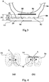
- the figure 2 illustrates a housing 12 according to one of the objects of the invention. It is presented as a portable unit that can be placed on a taxiway. It has a substantially trapezoidal cross section.
- the box comprises two inclined portions, an access ramp 15 and an exit ramp 16. Between the two is a substantially horizontal portion 18.
- the portion 18 of the housing 12 protects one or a row of sensors 50 for performing the distance measurements.
- the base 20 of the housing is placed against the running ground and provides it with the necessary stability during operation of the system.
- the housing 12 also includes an electronics 40 with a source of energy that supplies the sensors 50 with alternating current. The measurements are made when the contact area of the tire rests on the horizontal portion 18. This horizontal portion is the face of the tire. applying the case against the surface of the tread of the tire.
- the housing 12 is made of a non-conductive material whose magnetic properties are similar to those of air so as not to disturb the measurements.
- the housing can be embedded in a rolling floor or of suitable size and weight to be applied against a sidewall or an inner liner of a tire.
- FIG. figure 3 The measurement of the remaining thickness of rubbery material of a tread of a tire is illustrated in FIG. figure 3 .
- This figure shows a partial section of a tire 8 bearing on the application face 18 of a housing 12.
- the tire 8 comprises in particular a tread 80 with sculptures 82, a crown reinforcement 84 consisting of two or more plies of metal reinforcements (not shown), and flanks 86.
- the housing 12 comprises an application face 18, a base 20 and a row of sensors 50.
- the rolling surface 88 of the tread 80 bears against the application face 18 of the housing 12.
- the sensors 50 measure, as will be explained below, the distance D1 which separates them from the metal frame 84 from the top of the tire 8.
- D1 has three components. Two of these components are fixed, the distance D2 which separates the bottom of the sculptures 82 from the armature 84, and the distance D3 which separates the sensors 50 from the application face 18 of the casing 12.
- the distance D2 can be known from the identification of the type of tire measured. This identification can be manual or automatic, for example by retrieving identification data entered in a transponder such as an RFID incorporated in the tire structure.
- the figure 4 illustrates the operating principle of the sensor of a measuring system according to an object of the invention.
- an air coil 10 is shown with an axis of symmetry and sensitivity A.
- the magnetic field lines 54 emitted by this device extend into the air all around the coil. the coil as schematized at the Fig. 4 (a) .
- the figure 5 presents a schematic example of operation of an embodiment of a measuring system in the case of a coil and a U-shaped ferrite.
- the layer 21 whose thickness d is to be measured comprises a layer of rubbery material 24 adjacent to a reinforcement 22 made up of reinforcements whose magnetic permeability is greater than the magnetic permeability of the air, such as those conventionally used for carcass plies or tire top plies, including heavyweight.
- the housing 12 of the measuring system comprises a sensor 50 which comprises a coil 10 arranged around one of the lateral branches 36 of a U-shaped ferrite 30.
- the presence of the ferrite 30 makes it possible to locate the circulation of the lines of magnetic field through it and so locate the measurement area.
- the two bars of the U are separated by a distance l1 .
- the housing 12 has its application face 18 bearing against the free face 26 of the layer 21.
- the frequency and the excitation power of the coil 10 are such that the inductance across the coil increases as the distance d decreases.
- the mode of operation of the sensor is thus a reluctant mode thus related to the magnetic permeability of the different parts of the magnetic circuit.
- the magnetic permeability of the rubbery material is much lower than that of the adjacent reinforcement which is itself smaller than that of the ferrite.
- the reluctance of the layer 24 of rubbery material is much greater than that of the adjacent armature 22 which is itself greater than that of the ferrite 30.
- the variation of inductance measured across the coil 10 is mainly related to the variation of the distance d, thickness of the layer of rubber material because any change in the reluctance of the adjacent reinforcement bonded by the number of reinforcements or their construction has only a minor influence on the accuracy of the measurement.
- the accuracy and sensitivity of such a sensor reluctant mode are good.
- the range of the sensor is related to the distance l1 , distance between the two bars of the U, and to the section of the poles constituted by these two parallel bars.
- the Figures 6 to 8 present alternative embodiments of sensors.
- the senor 60 comprises a U-shaped ferrite 64 and a coil 62 disposed around the central bar of the U.
- the senor 70 comprises an E-shaped ferrite 74 and a coil 72 disposed around the center bar of the E.
- the senor 90 comprises a ferrite 94 in the form of a pot with an axis of symmetry and a central bar disposed substantially along this axis of symmetry and a coil 92 arranged around the central bar of the pot.
- the Figure 8 (a) presents a perspective view of the sensor and the figure 8 (b) a section along the axis of symmetry.
- This potted structure has the advantage of being insensitive to the anisotropy of the internal metal architecture of the tire.
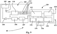
- the figure 9 shows an example of the structure of the electronics 40 for measuring the thickness of a tire rubber layer.
- This electronics consists of a “sensor module” 100 and a “motherboard” 120. It thus makes it possible to measure the layer thickness at a single point.
- the inductance L of the sensor increases when the distance d between the sensor and an adjacent layer, consisting of metal tire cables, decreases.
- This electronics therefore aims to measure the inductance L of the sensor coil, in order to deduce this distance between the sensor and the adjacent layer.
- This current I is generated by a current amplifier 104, itself controlled by an oscillator 106, whose frequency is imposed by a time base 107.
- the amplifiers, oscillator and time base are part of the "sensor module”.
- the two signals X and Y are then filtered by the filters 112 and digitized by means of analog / digital converters (ADC) 114 and then injected into the microcontroller 122 of the "motherboard" 120.
- ADC analog / digital converters
- the microcontroller 122 deduces from X and Y the value of the inductance L of the sensor 102. It first calculates the value of the amplitude of the voltage U across the sensor using the formula above.
- the set has the ability to perform many measurements on tires, without changing batteries, which gives the system autonomy for several years without human intervention.
Description
La présente invention est relative à un système de mesure de l'épaisseur d'une couche de gomme et plus particulièrement à la mesure de l'épaisseur de gomme restante d'une bande de roulement d'un pneumatique.The present invention relates to a system for measuring the thickness of a rubber layer and more particularly to the measurement of the remaining rubber thickness of a tread of a tire.
De manière connue, la bande de roulement d'un bandage pneumatique ou plus simplement pneumatique, qu'il soit destiné à équiper un véhicule de tourisme, poids lourd, Génie Civil ou autre..., est pourvue d'une sculpture comprenant notamment des éléments de sculpture ou blocs élémentaires délimités par diverses rainures principales, longitudinales, transversales ou encore obliques, les blocs élémentaires pouvant en outre comporter diverses incisions ou lamelles plus fines. Les rainures constituent des canaux destinés à évacuer l'eau lors d'un roulage sur sol mouillé et définissent les bords d'attaque des éléments de sculpture.In known manner, the tread of a tire or more simply pneumatic, whether it is intended to equip a passenger vehicle, truck, civil engineering or other ..., is provided with a sculpture comprising in particular elements of sculpture or elementary blocks delimited by various main grooves, longitudinal, transverse or oblique, the elementary blocks may further comprise various incisions or slices finer. The grooves are channels for evacuating water during a wet run and define the leading edges of the carving elements.
Quand un pneumatique est neuf, la bande de roulement a sa hauteur maximale. Cette hauteur initiale peut varier en fonction du type de pneumatique considéré ainsi que de l'usage auquel il est destiné ; à titre d'exemple, les pneumatiques « hiver » ont généralement une profondeur de sculpture supérieure à celle de pneumatiques « été ». Lorsque le pneumatique s'use, la hauteur des blocs élémentaires de la sculpture diminue et la raideur de ces blocs élémentaires augmente. L'augmentation de raideur des blocs élémentaires de sculpture entraîne une diminution de certaines performances du pneumatique, telle l'adhérence sur sol mouillé. De plus, les capacités d'évacuation d'eau diminuent fortement lorsque la profondeur des canaux des sculptures diminue.When a tire is new, the tread has its maximum height. This initial height may vary depending on the type of tire considered and the purpose for which it is intended; for example, "winter" tires generally have a greater tread depth than that of "summer" tires. When the tire wears out, the height of the elementary blocks of the sculpture decreases and the stiffness of these elementary blocks increases. Increasing the stiffness of the elementary blocks of sculpture results in a decrease in certain tire performance, such as wet grip. In addition, the water evacuation capacities decrease sharply when the depth of the channels of the sculptures decreases.
Il est donc souhaitable de pouvoir suivre l'évolution de l'usure de la bande de roulement d'un pneumatique.It is therefore desirable to be able to follow the evolution of the wear of the tread of a tire.
Un tel suivi est usuellement réalisé par observation visuelle de la bande de roulement par l'usager ou un garagiste avec ou sans une mesure effective avec une jauge de profondeur. Mais cette observation n'est pas très aisée à réaliser notamment sur les pneumatiques arrière d'accès plus difficile et n'est pas non plus très précise.Such tracking is usually done by visual observation of the tread by the user or a garage with or without an actual measurement with a gauge. depth. But this observation is not very easy to achieve especially on the rear tires of access more difficult and is also not very accurate.
De nombreuses propositions ont été faites pour automatiser la mesure de la profondeur de sculptures de pneumatiques. De tels dispositifs peuvent être disposés sur le sol de roulage des véhicules. Ces dispositifs fonctionnent usuellement selon deux techniques, soit à base de systèmes optiques avec des caméras ou des lasers, soit à base de courants de Foucault.Many proposals have been made to automate the measurement of tire tread depth. Such devices can be arranged on the running floor of the vehicles. These devices usually operate according to two techniques, either based on optical systems with cameras or lasers, or based on eddy currents.
Les systèmes à base de systèmes optiques sont coûteux, doivent être encastrés dans le sol de roulage et nécessitent une maintenance régulière. Les mesures sont de plus perturbées par des salissures et la présence ou des projections d'eau, de boue, de neige, etc.Systems based on optical systems are expensive, must be embedded in the running floor and require regular maintenance. The measurements are further disturbed by dirt and the presence or splashing of water, mud, snow, etc.
Les documents
Or, on a constaté que ces systèmes de mesures n'étaient pas totalement satisfaisants dans certains cas. En effet, l'armature de certains pneumatiques est telle que le sommet du pneumatique n'est pas suffisamment conducteur pour permettre l'établissement de courants de Foucault. Par conséquent, ces systèmes de mesure sont inadaptés à la mesure d'épaisseur de la bande de roulement de ces pneumatiques.However, it has been found that these measurement systems are not totally satisfactory in certain cases. Indeed, the armature of some tires is such that the crown of the tire is not sufficiently conductive to allow the establishment of eddy currents. Consequently, these measurement systems are unsuitable for measuring the thickness of the tread of these tires.
L'invention concerne, selon un objet décrit dans la revendication 1, un système de mesure de l'épaisseur d'une couche de matériau caoutchouteux d'un pneumatique, la couche comportant une face liée à une armature adjacente réalisée avec au moins un matériau de perméabilité magnétique supérieure à la perméabilité magnétique de l'air et une face libre en contact avec l'air, le système comprenant un capteur capable de mesurer la distance d entre la face liée et la face libre de la couche de matériau caoutchouteux. Le capteur comporte une unique bobine d'excitation et de mesure, et la fréquence et la puissance d'excitation de la bobine sont telles que l'inductance aux bornes de la bobine augmente lorsque la distance d diminue. La bobine est disposée autour, ou est entourée par un matériau à haute résistivité électrique et haute perméabilité magnétique. Le système comprend de plus un boîtier portatif en matériau non conducteur protégeant le capteur et comprenant deux portions inclinées formant une rampe d'accès et une rampe de sortie entre lesquelles se trouve une portion horizontale formant la face d'application du boîtier contre la surface de la bande de roulement du pneumatique.The invention relates, according to an object described in claim 1, a system for measuring the thickness of a layer of rubbery material of a tire, the layer comprising a face bonded to an adjacent reinforcement made with at least one material magnetic permeability greater than the magnetic permeability of the air and a free face in contact with the air, the system comprising a sensor capable of measuring the distance d between the bonded face and the free face of the layer of rubbery material. The sensor has a single excitation and measurement coil, and the frequency and the excitation power of the coil are such that the inductance across the coil increases as the distance d decreases. The coil is disposed around, or is surrounded by, a material with high electrical resistivity and high magnetic permeability. The system further comprises a portable housing of non-conductive material protecting the sensor and comprising two portions inclined forming an access ramp and an exit ramp between which there is a horizontal portion forming the application face of the housing against the surface of the tread of the tire.
Le capteur du système de mesure selon un objet de l'invention a l'avantage de fonctionner en mode reluctant, donc avec, à puissance donnée, une fréquence d'excitation de la bobine plus faible que dans le cas d'un capteur similaire fonctionnant dans un mode sensible aux courants de Foucault.The sensor of the measuring system according to an object of the invention has the advantage of operating in reluctant mode, so with, at given power, a lower excitation frequency of the coil than in the case of a similar sensor operating in a mode sensitive to eddy currents.
Par ailleurs, la mesure en mode reluctant met à profit la perméabilité magnétique de l'armature adjacente et on constate que cela offre une grande sensibilité des mesures à toute variation de la distance d.On the other hand, the reluctant measurement takes advantage of the magnetic permeability of the adjacent reinforcement and it is found that this gives a great sensitivity of the measurements to any variation of the distance d .
De préférence, la bobine du capteur est disposée autour, ou est entourée par, un matériau à haute résistivité électrique et haute perméabilité magnétique.Preferably, the sensor coil is disposed around, or is surrounded by, a high electrical resistivity and high magnetic permeability material.
La présence de ce matériau à haute résistivité électrique et haute perméabilité magnétique, tel une ferrite, a l'avantage de localiser les lignes de champ magnétique et ainsi de réaliser une mesure d'épaisseur de couche plus localisée.The presence of this material with high electrical resistivity and high magnetic permeability, such as a ferrite, has the advantage of locating the magnetic field lines and thus making a more localized layer thickness measurement.
La ferrite peut avoir une forme de U.Ferrite can be U-shaped.
La bobine est alors préférentiellement disposée autour de l'une des branches latérales du U.The coil is then preferably arranged around one of the lateral branches of the U.
Alternativement, la bobine peut être disposée autour du fond du U de la ferrite.Alternatively, the coil may be disposed around the bottom of the U of the ferrite.
Dans ce mode de réalisation, la portée du capteur peut être améliorée simplement en augmentant l'écart entre les deux extrémités du U.In this embodiment, the sensor range can be improved simply by increasing the gap between the two ends of the U.
On peut également augmenter cette portée en augmentant la section des pôles constitués par les deux barres parallèles du circuit en forme de U.This range can also be increased by increasing the section of the poles constituted by the two parallel bars of the U-shaped circuit.
Selon un autre mode de réalisation, la bobine d'excitation et de mesure est disposée autour d'un matériau à haute résistivité électrique et haute perméabilité magnétique en forme de E.According to another embodiment, the excitation and measurement coil is arranged around a high electrical resistivity material and high E-shaped magnetic permeability.
Dans ce mode de réalisation, la bobine est avantageusement disposée autour de la barre centrale du E.In this embodiment, the coil is advantageously arranged around the central bar of E.
Dans ce mode de réalisation, la portée du capteur peut être améliorée simplement en augmentant l'écart entre la barre centrale du E et les deux barres externes de celui-ci.In this embodiment, the range of the sensor can be improved simply by increasing the gap between the central bar of the E and the two outer bars thereof.
On peut également augmenter cette portée en augmentant la section des pôles constitués par les trois barres parallèles du circuit en forme de E.This range can also be increased by increasing the section of the poles formed by the three parallel bars of the E-shaped circuit.
Selon un troisième mode de réalisation, la bobine d'excitation et de mesure est disposée autour d'un matériau à haute résistivité électrique et haute perméabilité magnétique, le matériau présentant un axe de symétrie et selon toute coupe axiale une forme de E.According to a third embodiment, the excitation and measurement coil is arranged around a material with high electrical resistivity and high magnetic permeability, the material having an axis of symmetry and in any axial section a form of E.
Dans ce mode de réalisation dit « en pot », la bobine est disposée autour de l'axe central du circuit magnétique.In this so-called "pot" embodiment, the coil is arranged around the central axis of the magnetic circuit.
Dans ce mode de réalisation, la portée du capteur peut-être améliorée simplement en augmentant le diamètre externe de la structure en pot, de sorte que l'écart entre le pôle central et le pôle externe soit plus important.In this embodiment, the range of the sensor can be improved simply by increasing the outer diameter of the potted structure, so that the gap between the center pole and the outer pole is greater.
On peut également augmenter cette portée en augmentant la section des deux pôles de la structure en pot.This range can also be increased by increasing the section of the two poles of the potted structure.
Ce mode de réalisation axisymétrique présente l'avantage d'être insensible à l'orientation des câbles métalliques constituant l'armature adjacente. Le capteur est donc insensible à l'anisotropie de cette couche adjacente.This axisymmetric embodiment has the advantage of being insensitive to the orientation of the metal cables constituting the adjacent reinforcement. The sensor is therefore insensitive to the anisotropy of this adjacent layer.
Avantageusement, la bobine d'excitation et de mesure est alimentée par une source électrique alternative.Advantageously, the excitation and measurement coil is powered by an alternating electric source.
En utilisant une fréquence d'alimentation alternative, il est avantageux de limiter celle-ci en dessous de 150 kHz, on limite alors très fortement la génération de courants de Foucault dans l'armature adjacente de la couche. Par ailleurs, en dépassant une fréquence de 10 kHz, on s'affranchit des bruits classiques mesurés par une antenne en champ proche.By using an alternating supply frequency, it is advantageous to limit it to below 150 kHz, the generation of eddy currents in the adjacent armature of the layer is then very strongly limited. In addition, exceeding a frequency of 10 kHz, it eliminates conventional noise measured by a near-field antenna.
D'autre part, plus on augmente la fréquence d'alimentation pour un courant donné, plus on améliore la résolution temporelle de la mesure. Enfin, l'augmentation de la fréquence permet de diminuer le temps de mesure ce qui a un impact favorable sur la consommation électrique de l'ensemble.On the other hand, the more the supply frequency is increased for a given current, the better the temporal resolution of the measurement. Finally, the increase in the frequency makes it possible to reduce the measurement time which has a favorable impact on the electrical consumption of the whole.
On a constaté qu'il est avantageux d'utiliser une fréquence d'alimentation comprise entre 40 et 80 kHz.It has been found that it is advantageous to use a power frequency of between 40 and 80 kHz.
Pour évaluer la distance d entre le capteur et l'armature métallique de pneumatique, on peut mesurer l'impédance complexe ou seulement une partie de cette impédance telle que la résistance ou l'inductance.To evaluate the distance d between the sensor and the metal armature of the tire, it is possible to measure the complex impedance or only a part of this impedance such as resistance or inductance.
On peut également mesurer la phase ou le module de l'impédance complexe.It is also possible to measure the phase or the modulus of the complex impedance.
Avantageusement, on mesure l'inductance de la bobine.Advantageously, the inductance of the coil is measured.
Par exemple, on peut mesurer l'inductance de la bobine au moyen de la formule suivante : ![]()
![]()
Pour ce faire on peut alimenter la bobine au moyen d'un courant sinusoïdal stationnaire connu, ce qui permet d'en connaître précisément la dérivée par rapport au temps, et on peut utiliser un dispositif de mesure de l'amplitude de la tension aux bornes de la bobine.To do this, the coil can be powered by means of a known stationary sinusoidal current, which makes it possible to precisely know the derivative with respect to time, and it is possible to use a device for measuring the amplitude of the voltage at the terminals. of the coil.
Ce dispositif de mesure d'amplitude de la tension aux bornes de la bobine peut mesurer en continu la tension ou utiliser un système de démodulation d'amplitude.This device for measuring the amplitude of the voltage across the coil can continuously measure the voltage or use an amplitude demodulation system.
Le système de mesure est avantageusement disposé dans un boîtier non conducteur électrique et dont les matériaux ont une susceptibilité magnétique nulle ou suffisamment faible pour être assimilable à l'air ou le vide.The measuring system is advantageously arranged in a non-conducting electrical housing and whose materials have a magnetic susceptibility zero or sufficiently low to be comparable to air or vacuum.
De préférence, la bobine ayant un axe de sensibilité et le boitier ayant une face d'application contre la face libre de la couche dont l'épaisseur est à mesurer, la face d'application du boitier est normale à l'axe de sensibilité de la bobine.Preferably, the coil having a sensitivity axis and the housing having an application face against the free face of the layer whose thickness is to be measured, the application face of the housing is normal to the sensitivity axis of the housing. the coil.
Le boitier peut être un boitier portatif.The case can be a portable case.
Dans ce cas, le système de mesure selon un objet de l'invention peut être appliqué à la mesure de l'épaisseur de matériau caoutchouteux d'un flanc ou d'une gomme intérieure d'un pneumatique. Cette mesure peut être réalisée lors de la fabrication du pneumatique ou après la fin de celle-ci.In this case, the measuring system according to an object of the invention can be applied to the measurement of the thickness of rubbery material of a sidewall or an inner liner of a tire. This measurement can be made during the manufacture of the tire or after the end of it.
Le boitier peut aussi être apte à être disposé sur ou encastré dans un sol de roulage.The housing can also be adapted to be placed on or embedded in a taxiway.
Dans ce cas, le système de mesure est de préférence appliqué à la mesure de l'épaisseur de matériau caoutchouteux restante d'une bande de roulement d'un pneumatique.In this case, the measuring system is preferably applied to the measurement of the remaining rubber material thickness of a tread of a tire.
Bien entendu, la bobine d'excitation et de mesure du système de mesure selon un objet de l'invention peut être constituée d'une pluralité de bobines connectées en série ou en parallèle.Of course, the excitation and measurement coil of the measuring system according to an object of the invention may consist of a plurality of coils connected in series or in parallel.
L'invention s'applique particulièrement aux pneumatiques comportant des renforts métalliques dans leur sommet et/ou leurs nappes carcasses tels ceux destinés à équiper des véhicules à moteur de type tourisme, SUV ("Sport Utility Vehicles"), comme des véhicules industriels choisis parmi camionnettes, « Poids-lourd » - c'est-à-dire métro, bus, engins de transport routier (camions, tracteurs, remorques), véhicules hors-la-route tels qu'engins de génie civil -, autres véhicules de transport ou de manutention.The invention is particularly applicable to tires comprising metal reinforcements in their crowns and / or their carcass plies, such as those intended for equipping tourism-type motor vehicles, SUVs (" Sport Utility Vehicles "), such as industrial vehicles chosen from vans, "heavy goods vehicles" - that is, metros, buses, road transport vehicles (trucks, tractors, trailers), off-the-road vehicles such as civil engineering vehicles -, other transport vehicles or handling.
Les figures annexées illustrent plusieurs modes de réalisation d'un système de mesure selon un objet de l'invention en prenant comme exemple principal son application à la mesure de l'épaisseur de bandes de roulement de pneumatiques :
- la
figure 1 est une vue en perspective d'un véhicule dont un pneumatique passe au-dessus d'un boitier comportant un système de mesure selon un objet de l'invention ; - la
figure 2 présente un boitier avec un système de mesure ; - la
figure 3 présente une coupe d'un pneumatique en contact avec le boitier du système de mesure ; - la
figure 4 présente le principe de fonctionnement d'un système de mesure dans le cas d'une bobine à air, en l'absence (a) et en présence (b) d'une plaque métallique ; - la
figure 5 présente de façon schématique un exemple de fonctionnement du système de mesure dans le cas d'une bobine avec une ferrite en forme de U ; - la
figure 6 présente un mode de réalisation alternatif du système de lafigure 5 ; - la
figure 7 présente un deuxième mode de réalisation avec une ferrite en forme de E ; - la
figure 8 présente un troisième mode de réalisation avec une ferrite en forme de pot ; - la
figure 9 présente schématiquement une structure de l'électronique d'un système de mesure.
- the
figure 1 is a perspective view of a vehicle with a tire passing over a housing having a measuring system according to an object of the invention; - the
figure 2 presents a box with a measuring system; - the
figure 3 has a section of a tire in contact with the housing of the measuring system; - the
figure 4 presents the principle of operation of a measuring system in the case of an air coil, in the absence (a) and in the presence (b) of a metal plate; - the
figure 5 schematically shows an example of operation of the measuring system in the case of a coil with a U-shaped ferrite; - the
figure 6 presents an alternative embodiment of the system offigure 5 ; - the
figure 7 presents a second embodiment with an E-shaped ferrite; - the
figure 8 presents a third embodiment with a pot-shaped ferrite; - the
figure 9 schematically presents a structure of the electronics of a measuring system.
La
La
Selon d'autres modes de réalisation, le boitier peut être encastré dans un sol de roulage ou de dimensions et de poids approprié pour pouvoir être appliqué contre un flanc ou une gomme intérieure d'un pneumatique.According to other embodiments, the housing can be embedded in a rolling floor or of suitable size and weight to be applied against a sidewall or an inner liner of a tire.
La mesure de l'épaisseur restante de matériau caoutchouteux d'une bande de roulement d'un pneumatique est illustrée à la
Les capteurs 50 mesurent, comme il sera expliqué ci-dessous, la distance D1 qui les sépare de l'armature métallique 84 du sommet du pneumatique 8. D1 a trois composantes. Deux de ces composantes sont fixes, la distance D2 qui sépare le fond des sculptures 82 de l'armature 84, et la distance D3 qui sépare les capteurs 50 de la face d'application 18 du boitier 12. Une composante est variable avec le degré d'usure de la bande de roulement, c'est d qui correspond à l'épaisseur restante de la bande de roulement. On a : ![]()
![]()
La distance D2 peut être connue à partir de l'identification du type de pneumatique mesuré. Cette identification peut être manuelle ou automatique, par exemple en récupérant des données d'identification inscrites dans un transpondeur tel un RFID incorporé dans la structure du pneumatique.The distance D2 can be known from the identification of the type of tire measured. This identification can be manual or automatic, for example by retrieving identification data entered in a transponder such as an RFID incorporated in the tire structure.
La
A la
Si on approche de ce dispositif une armature métallique 14, bonne conductrice de champ magnétique et mauvaise conductrice électrique, telle une nappe sommet d'un pneumatique constituée de renforts métalliques parallèles noyés dans deux couches de matériau caoutchouteux peu conducteur, les lignes de champ vont naturellement chercher à passer par cette armature métallique plutôt que dans l'air, car l'air a une reluctance supérieure à celle de l'armature métallique. On observe une localisation des lignes de champ magnétique 54 à travers l'armature métallique 14.If we approach this device a
Il en résulte que dans la zone située entre la bobine 10 et l'armature métallique, la densité de flux magnétique va augmenter.As a result, in the area between the
On peut ainsi obtenir une mesure de la variation de position de l'armature métallique 14 relativement à la bobine 10 par une mesure de la variation de l'inductance de la bobine 10.It is thus possible to obtain a measurement of the position variation of the
La
La couche 21 dont on veut mesurer l'épaisseur d comporte une couche de matériau caoutchouteux 24 adjacente à une armature 22 constituée de renforts dont la perméabilité magnétique est supérieure à la perméabilité magnétique de l'air tels que ceux usuellement utilisés pour des nappes carcasses ou des nappes sommet de pneumatiques, notamment poids-lourd.The
Le boitier 12 du système de mesure comporte un capteur 50 qui comporte une bobine 10 disposée autour de l'une des branches latérales 36 d'une ferrite 30 en forme de U. La présence de la ferrite 30 permet de localiser la circulation des lignes de champ magnétique à travers elle et ainsi de localiser la zone de mesure. Les deux barres du U sont éloignées d'une distance l1.The
Le boitier 12 a sa face d'application 18 en appui contre la face libre 26 de la couche 21.The
Selon une caractéristique essentielle du système de mesure, la fréquence et la puissance d'excitation de la bobine 10 sont telles que l'inductance aux bornes de la bobine augmente lorsque la distance d diminue.According to an essential characteristic of the measuring system, the frequency and the excitation power of the
Le mode de fonctionnement du capteur est ainsi un mode reluctant donc lié à la perméabilité magnétique des différentes parties du circuit magnétique.The mode of operation of the sensor is thus a reluctant mode thus related to the magnetic permeability of the different parts of the magnetic circuit.
La perméabilité magnétique du matériau caoutchouteux est très inférieure à celle de l'armature adjacente qui est elle-même inférieure à celle de la ferrite.The magnetic permeability of the rubbery material is much lower than that of the adjacent reinforcement which is itself smaller than that of the ferrite.
En conséquence, la reluctance de la couche 24 de matériau caoutchouteux est très supérieure à celle de l'armature adjacente 22 qui est elle-même supérieure à celle de la ferrite 30. Cela implique que la variation d'inductance mesurée aux bornes de la bobine 10 est principalement liée à la variation de la distance d, épaisseur de la couche de matériau caoutchouteux parce que toute variation de la reluctance de l'armature adjacente liée par exemple au nombre de renforts ou à leur construction n'a qu'une influence mineure sur la précision de la mesure. La précision et la sensibilité d'un tel capteur en mode reluctant sont donc bonnes. La portée du capteur est liée à la distance l1, distance entre les deux barres du U, et à la section des pôles constitués par ces deux barres parallèles.As a result, the reluctance of the
Les
A la
A la
A la
Cette structure en pot présente l'avantage d'être insensible à l'anisotropie de l'architecture métallique interne au pneumatique.This potted structure has the advantage of being insensitive to the anisotropy of the internal metal architecture of the tire.
La
Cette électronique est constituée d'un «module capteur» 100 et d'une «carte mère » 120. Elle permet donc de réaliser une mesure d'épaisseur de couche en un unique point.This electronics consists of a "sensor module" 100 and a "motherboard" 120. It thus makes it possible to measure the layer thickness at a single point.
Pour étendre le principe de ce schéma à un système constitué d'une multiplicité de capteurs, il suffit d'utiliser plusieurs « modules capteurs » tous reliés à la même « carte mère ».To extend the principle of this scheme to a system consisting of a multiplicity of sensors, it is sufficient to use several "sensor modules" all connected to the same "motherboard".
En mode reluctant, l'inductance L du capteur augmente lorsque la distance d entre le capteur et une couche adjacente, constituée de câbles métalliques de pneumatique, diminue. Cette électronique a donc pour but de mesurer l'inductance L de la bobine du capteur, afin de pouvoir déduire cette distance entre le capteur et la couche adjacente.In reluctant mode, the inductance L of the sensor increases when the distance d between the sensor and an adjacent layer, consisting of metal tire cables, decreases. This electronics therefore aims to measure the inductance L of the sensor coil, in order to deduce this distance between the sensor and the adjacent layer.
Le «module capteur» 100 est constitué, entre autre, d'un capteur 102 comme précédemment décrit, alimenté par un courant I qui est pris comme référence de phase (φ=0). Ce courant I est généré par un amplificateur en courant 104, lui-même piloté par un oscillateur 106, dont la fréquence est imposée par une base de temps 107. Les amplificateur, oscillateur et base de temps font partie du « module capteur ».The "sensor module" 100 consists, among other things, of a
La tension U, de phase φ non nulle par rapport au courant I, prélevée aux bornes du capteur, est d'abord amplifiée par l'amplificateur 108 puis injectée dans un double démodulateur 110, de même que le signal de sortie de l'oscillateur 106.The voltage U, phase φ non-zero with respect to the current I, taken at the terminals of the sensor, is first amplified by the
En sortie du démodulateur 110, on trouve les signaux X et Y qui représentent les deux composantes complexes décrivant la tension aux bornes du capteur, telles que : ![]()
![]()
Les deux signaux X et Y sont ensuite filtrés par les filtres 112 et numérisés au moyen de convertisseurs analogique/numérique (ADC) 114, puis injectés dans le microcontrôleur 122 de la « carte mère » 120.The two signals X and Y are then filtered by the
Le microcontrôleur 122 déduit de X et Y la valeur de l'inductance L du capteur 102. Il calcule d'abord la valeur de l'amplitude de la tension U aux bornes du capteur en utilisant la formule ci-dessus.The
Dans un second temps, il déduit de cette valeur l'inductance L de la bobine du capteur, la valeur du courant I injecté dans le capteur étant connue, au moyen de la formule suivante : 
La carte mère est également munie de plusieurs blocs fonctionnels additionnels :
- une mémoire 124 afin de permettre l'enregistrement des mesures réalisées par le capteur 102 ;
un décodeur RFID 126 qui permet l'identification du pneumatique, au moyen d'une antenne 128, lorsque cela peut se faire en mettant à profit la présence de RFID incorporé dans la structure du pneumatique ;- un module de communication sans
fil 130 qui permet l'envoi des informations à distance, via une antenne supplémentaire 132 ; et une alimentation 134 distribuant le courant nécessaire à l'ensemble du système, à partir d'unebatterie 136.
- a
memory 124 to allow the recording of the measurements made by thesensor 102; - an
RFID decoder 126 which allows the identification of the tire, by means of anantenna 128, when this can be done by taking advantage of the presence of RFID incorporated in the tire structure; - a
wireless communication module 130 which allows the sending of information remotely via anadditional antenna 132; and - a
power supply 134 distributing the current required for the entire system, from abattery 136.
L'ensemble a la capacité à réaliser des mesures nombreuses sur des pneumatiques, sans changement de batteries, ce qui confère au système une autonomie de plusieurs années sans intervention humaine.The set has the ability to perform many measurements on tires, without changing batteries, which gives the system autonomy for several years without human intervention.
Claims (20)
- System for measuring the thickness of a layer of rubber material of a tyre, said layer comprising a face joined to an adjacent reinforcement made with at least one material having a magnetic permeability greater than the magnetic permeability of air, and a free face in contact with the air, said system comprising a sensor capable of measuring the distance d between the joined face and the free face of said layer of rubber material, the sensor comprising a single excitation and measurement coil, and the excitation frequency and power of said coil are such that the inductance at the terminals of said coil increases when the distance d decreases, and the coil of the sensor is positioned around, or is surrounded by, a material having high electrical resistivity and high magnetic permeability said system also comprising a portable casing made of a non-conductive material, for protecting the sensor, and comprising two inclined portions, forming an access ramp and an exit ramp between which these two portions there is a substantially horizontal portion forming the application face of the casing against the tyre tread.
- Measurement system according to Claim 2, wherein said material having high electrical resistivity and high magnetic permeability is U-shaped.
- Measurement system according to Claim 3, wherein said coil is positioned around one of the lateral branches of the U.
- Measurement system according to Claim 3, wherein said coil is positioned around the bottom of the U.
- Measurement system according to Claim 2, wherein said material having high electrical resistivity and high magnetic permeability is E-shaped.
- Measurement system according to Claim 1, wherein said material having high electrical resistivity and high magnetic permeability has an axis of symmetry and is E-shaped in any axial cross section.
- Measurement system according to one of Claims 5 and 6, wherein said coil is positioned around the central bar of the E.
- Measurement system according to any of Claims 1 to 7, wherein the material having high electrical resistivity and high magnetic permeability is a ferrite.
- Measurement system according to any of the preceding claims, wherein said excitation and measurement coil is supplied by an alternating power source.
- Measurement system according to Claim 9, wherein said excitation and measurement coil is supplied by an alternating power source having a frequency of more than 10 kHz and less than 150 kHz.
- Measurement system according to Claim 10, wherein said excitation and measurement coil is supplied by an alternating power source having a frequency in the range from 40 kHz to 80 kHz.
- Measurement system as claimed in any of the preceding claims, wherein the complex impedance, or a part of this impedance such as the resistance, the inductance, the phase or the modulus of the complex impedance, is measured.
- Measurement system according to Claim 12, wherein the inductance of the coil is measured.
- Measurement system according to any of the preceding claims, such that it is positioned inside an electrically non-conductive casing and is made of materials with a magnetic susceptibility equal to zero or sufficiently low to be similar to that of air or a vacuum.
- Measurement system according to Claim 14, wherein the coil has an axis of sensitivity and said casing has a face for application against the free face of said layer, and said application face is perpendicular to the axis of sensitivity of the coil.
- Measurement system according to one of Claims 14 and 15, such that said casing is a portable casing.
- Measurement system according to one of Claims 14 and 15, such that said casing can be positioned on, or embedded in, a roadway.
- Measurement system according to any of the preceding claims, wherein the excitation and measurement coil is formed by a plurality of coils connected in series or in parallel.
- Use of the measurement system according to any of the preceding claims for measuring the thickness of remaining rubber material on a tread of said tyre.
- Use of the measurement system according to any of Claims 1 to 16 for measuring the thickness of rubber material of a sidewall or internal rubber element of said tyre.
Applications Claiming Priority (2)
| Application Number | Priority Date | Filing Date | Title |
|---|---|---|---|
| FR1355850A FR3007516B1 (en) | 2013-06-20 | 2013-06-20 | SYSTEM FOR MEASURING THE THICKNESS OF A GUM LAYER OF A TIRE |
| PCT/EP2014/062998 WO2014202746A1 (en) | 2013-06-20 | 2014-06-20 | System for measuring the thickness of a layer of rubber for a tyre |
Publications (2)
| Publication Number | Publication Date |
|---|---|
| EP3011264A1 EP3011264A1 (en) | 2016-04-27 |
| EP3011264B1 true EP3011264B1 (en) | 2019-01-09 |
Family
ID=49474544
Family Applications (1)
| Application Number | Title | Priority Date | Filing Date |
|---|---|---|---|
| EP14735491.4A Active EP3011264B1 (en) | 2013-06-20 | 2014-06-20 | System for measuring the thickness of a layer of rubber for a tyre |
Country Status (6)
| Country | Link |
|---|---|
| EP (1) | EP3011264B1 (en) |
| JP (1) | JP2016529479A (en) |
| CA (1) | CA2914522A1 (en) |
| FR (1) | FR3007516B1 (en) |
| MX (1) | MX351684B (en) |
| WO (1) | WO2014202746A1 (en) |
Families Citing this family (2)
| Publication number | Priority date | Publication date | Assignee | Title |
|---|---|---|---|---|
| JP2019211430A (en) * | 2018-06-08 | 2019-12-12 | 株式会社ブリヂストン | Method for detecting distortion of rubber member and device thereof, and tire for detecting internal distortion |
| WO2020121105A1 (en) * | 2018-12-11 | 2020-06-18 | Pirelli Tyre S.P.A. | Method and apparatus for checking the electrical conductivity of a tyre being processed |
Family Cites Families (11)
| Publication number | Priority date | Publication date | Assignee | Title |
|---|---|---|---|---|
| US4652820A (en) * | 1983-03-23 | 1987-03-24 | North American Philips Corporation | Combined position sensor and magnetic motor or bearing |
| JPH04343001A (en) * | 1991-05-20 | 1992-11-30 | Ishikawajima Harima Heavy Ind Co Ltd | Method and apparatus for inspecting position of cooling hole at end of turbine blade |
| JP2589420B2 (en) * | 1991-07-19 | 1997-03-12 | 古河電気工業株式会社 | Method and apparatus for inspecting conductive film |
| JPH07110203A (en) * | 1993-10-08 | 1995-04-25 | Japan Atom Energy Res Inst | Method and instrument for measuring thickness of build-up weld of reactor pressure vessel |
| DE19745734B4 (en) * | 1997-10-16 | 2007-07-05 | Bayerische Motoren Werke Ag | Abrasion sensor for detecting the tread depth of a tire of motor vehicles |
| JP4610062B2 (en) * | 2000-09-14 | 2011-01-12 | 株式会社ブリヂストン | Buffing method |
| US7112960B2 (en) * | 2003-07-31 | 2006-09-26 | Applied Materials, Inc. | Eddy current system for in-situ profile measurement |
| JP2005315734A (en) * | 2004-04-28 | 2005-11-10 | Jfe Steel Kk | Method and instrument for measuring displacement of ferromagnetic body |
| US20100139383A1 (en) * | 2006-11-17 | 2010-06-10 | Treadcheck Limited | Apparatus and method for monitoring tyre wear |
| US7578180B2 (en) | 2007-06-29 | 2009-08-25 | The Goodyear Tire & Rubber Company | Tread depth sensing device and method for measuring same |
| GB2470779A (en) * | 2009-06-05 | 2010-12-08 | Monitran Ltd | Eddy current proximity probe system and method of measuring that mitigates errors due to temperature fluctuations |
-
2013
- 2013-06-20 FR FR1355850A patent/FR3007516B1/en not_active Expired - Fee Related
-
2014
- 2014-06-20 EP EP14735491.4A patent/EP3011264B1/en active Active
- 2014-06-20 WO PCT/EP2014/062998 patent/WO2014202746A1/en active Application Filing
- 2014-06-20 MX MX2015016917A patent/MX351684B/en active IP Right Grant
- 2014-06-20 CA CA2914522A patent/CA2914522A1/en not_active Abandoned
- 2014-06-20 JP JP2016520504A patent/JP2016529479A/en active Pending
Non-Patent Citations (1)
| Title |
|---|
| None * |
Also Published As
| Publication number | Publication date |
|---|---|
| EP3011264A1 (en) | 2016-04-27 |
| CA2914522A1 (en) | 2014-12-24 |
| JP2016529479A (en) | 2016-09-23 |
| WO2014202746A1 (en) | 2014-12-24 |
| MX351684B (en) | 2017-10-25 |
| FR3007516A1 (en) | 2014-12-26 |
| FR3007516B1 (en) | 2017-04-28 |
| MX2015016917A (en) | 2016-04-04 |
Similar Documents
| Publication | Publication Date | Title |
|---|---|---|
| EP3025119B1 (en) | System for measuring the thickness of a tread layer of a tyre | |
| EP3025120A1 (en) | System for measuring the thickness of a liner layer of a tyre | |
| WO2014202747A1 (en) | System for measuring the thickness of a layer of rubber for a tyre | |
| EP1446296B1 (en) | Method for the continuous measurement of wear in relation to a tyre casing | |
| EP0649553B1 (en) | Device and process for the detection of one or more vehicle wheels | |
| EP3234540B1 (en) | Method for measuring the thickness of a layer of rubber-like material | |
| WO2015078911A1 (en) | System for the dynamic reading of data from transponders | |
| WO2015052439A1 (en) | Method of utilizing a system for monitoring the pressure and/or temperature of the tyres of a vehicle and device allowing implementation | |
| EP3011264B1 (en) | System for measuring the thickness of a layer of rubber for a tyre | |
| WO2015078912A1 (en) | System for the dynamic reading of data from transponders | |
| EP1977940A1 (en) | Method of detecting a hydroplaning phenomenon of a tyre on a road | |
| EP2300889B1 (en) | Method of guiding a vehicle | |
| WO2022123137A1 (en) | Measurement device comprising a system for mechanically uncoupling a hall effect sensor | |
| EP4259457A2 (en) | Tire, the tread of which comprises oriented fibers |
Legal Events
| Date | Code | Title | Description |
|---|---|---|---|
| PUAI | Public reference made under article 153(3) epc to a published international application that has entered the european phase |
Free format text: ORIGINAL CODE: 0009012 |
|
| 17P | Request for examination filed |
Effective date: 20160120 |
|
| AK | Designated contracting states |
Kind code of ref document: A1 Designated state(s): AL AT BE BG CH CY CZ DE DK EE ES FI FR GB GR HR HU IE IS IT LI LT LU LV MC MK MT NL NO PL PT RO RS SE SI SK SM TR |
|
| AX | Request for extension of the european patent |
Extension state: BA ME |
|
| DAX | Request for extension of the european patent (deleted) | ||
| RAP1 | Party data changed (applicant data changed or rights of an application transferred) |
Owner name: COMPAGNIE GENERALE DES ETABLISSEMENTS MICHELIN |
|
| RAP1 | Party data changed (applicant data changed or rights of an application transferred) |
Owner name: COMPAGNIE GENERALE DES ETABLISSEMENTS MICHELIN |
|
| STAA | Information on the status of an ep patent application or granted ep patent |
Free format text: STATUS: EXAMINATION IS IN PROGRESS |
|
| 17Q | First examination report despatched |
Effective date: 20180516 |
|
| GRAP | Despatch of communication of intention to grant a patent |
Free format text: ORIGINAL CODE: EPIDOSNIGR1 |
|
| STAA | Information on the status of an ep patent application or granted ep patent |
Free format text: STATUS: GRANT OF PATENT IS INTENDED |
|
| INTG | Intention to grant announced |
Effective date: 20180926 |
|
| RAP1 | Party data changed (applicant data changed or rights of an application transferred) |
Owner name: COMPAGNIE GENERALE DES ETABLISSEMENTS MICHELIN |
|
| GRAS | Grant fee paid |
Free format text: ORIGINAL CODE: EPIDOSNIGR3 |
|
| GRAA | (expected) grant |
Free format text: ORIGINAL CODE: 0009210 |
|
| STAA | Information on the status of an ep patent application or granted ep patent |
Free format text: STATUS: THE PATENT HAS BEEN GRANTED |
|
| AK | Designated contracting states |
Kind code of ref document: B1 Designated state(s): AL AT BE BG CH CY CZ DE DK EE ES FI FR GB GR HR HU IE IS IT LI LT LU LV MC MK MT NL NO PL PT RO RS SE SI SK SM TR |
|
| REG | Reference to a national code |
Ref country code: GB Ref legal event code: FG4D Free format text: NOT ENGLISH |
|
| REG | Reference to a national code |
Ref country code: CH Ref legal event code: EP Ref country code: AT Ref legal event code: REF Ref document number: 1087861 Country of ref document: AT Kind code of ref document: T Effective date: 20190115 |
|
| REG | Reference to a national code |
Ref country code: IE Ref legal event code: FG4D Free format text: LANGUAGE OF EP DOCUMENT: FRENCH |
|
| REG | Reference to a national code |
Ref country code: DE Ref legal event code: R096 Ref document number: 602014039550 Country of ref document: DE |
|
| REG | Reference to a national code |
Ref country code: NL Ref legal event code: MP Effective date: 20190109 |
|
| REG | Reference to a national code |
Ref country code: LT Ref legal event code: MG4D |
|
| PG25 | Lapsed in a contracting state [announced via postgrant information from national office to epo] |
Ref country code: NL Free format text: LAPSE BECAUSE OF FAILURE TO SUBMIT A TRANSLATION OF THE DESCRIPTION OR TO PAY THE FEE WITHIN THE PRESCRIBED TIME-LIMIT Effective date: 20190109 |
|
| REG | Reference to a national code |
Ref country code: AT Ref legal event code: MK05 Ref document number: 1087861 Country of ref document: AT Kind code of ref document: T Effective date: 20190109 |
|
| PG25 | Lapsed in a contracting state [announced via postgrant information from national office to epo] |
Ref country code: NO Free format text: LAPSE BECAUSE OF FAILURE TO SUBMIT A TRANSLATION OF THE DESCRIPTION OR TO PAY THE FEE WITHIN THE PRESCRIBED TIME-LIMIT Effective date: 20190409 Ref country code: ES Free format text: LAPSE BECAUSE OF FAILURE TO SUBMIT A TRANSLATION OF THE DESCRIPTION OR TO PAY THE FEE WITHIN THE PRESCRIBED TIME-LIMIT Effective date: 20190109 Ref country code: LT Free format text: LAPSE BECAUSE OF FAILURE TO SUBMIT A TRANSLATION OF THE DESCRIPTION OR TO PAY THE FEE WITHIN THE PRESCRIBED TIME-LIMIT Effective date: 20190109 Ref country code: SE Free format text: LAPSE BECAUSE OF FAILURE TO SUBMIT A TRANSLATION OF THE DESCRIPTION OR TO PAY THE FEE WITHIN THE PRESCRIBED TIME-LIMIT Effective date: 20190109 Ref country code: PL Free format text: LAPSE BECAUSE OF FAILURE TO SUBMIT A TRANSLATION OF THE DESCRIPTION OR TO PAY THE FEE WITHIN THE PRESCRIBED TIME-LIMIT Effective date: 20190109 Ref country code: PT Free format text: LAPSE BECAUSE OF FAILURE TO SUBMIT A TRANSLATION OF THE DESCRIPTION OR TO PAY THE FEE WITHIN THE PRESCRIBED TIME-LIMIT Effective date: 20190509 Ref country code: FI Free format text: LAPSE BECAUSE OF FAILURE TO SUBMIT A TRANSLATION OF THE DESCRIPTION OR TO PAY THE FEE WITHIN THE PRESCRIBED TIME-LIMIT Effective date: 20190109 |
|
| PG25 | Lapsed in a contracting state [announced via postgrant information from national office to epo] |
Ref country code: HR Free format text: LAPSE BECAUSE OF FAILURE TO SUBMIT A TRANSLATION OF THE DESCRIPTION OR TO PAY THE FEE WITHIN THE PRESCRIBED TIME-LIMIT Effective date: 20190109 Ref country code: LV Free format text: LAPSE BECAUSE OF FAILURE TO SUBMIT A TRANSLATION OF THE DESCRIPTION OR TO PAY THE FEE WITHIN THE PRESCRIBED TIME-LIMIT Effective date: 20190109 Ref country code: GR Free format text: LAPSE BECAUSE OF FAILURE TO SUBMIT A TRANSLATION OF THE DESCRIPTION OR TO PAY THE FEE WITHIN THE PRESCRIBED TIME-LIMIT Effective date: 20190410 Ref country code: BG Free format text: LAPSE BECAUSE OF FAILURE TO SUBMIT A TRANSLATION OF THE DESCRIPTION OR TO PAY THE FEE WITHIN THE PRESCRIBED TIME-LIMIT Effective date: 20190409 Ref country code: RS Free format text: LAPSE BECAUSE OF FAILURE TO SUBMIT A TRANSLATION OF THE DESCRIPTION OR TO PAY THE FEE WITHIN THE PRESCRIBED TIME-LIMIT Effective date: 20190109 Ref country code: IS Free format text: LAPSE BECAUSE OF FAILURE TO SUBMIT A TRANSLATION OF THE DESCRIPTION OR TO PAY THE FEE WITHIN THE PRESCRIBED TIME-LIMIT Effective date: 20190509 |
|
| REG | Reference to a national code |
Ref country code: DE Ref legal event code: R097 Ref document number: 602014039550 Country of ref document: DE |
|
| PG25 | Lapsed in a contracting state [announced via postgrant information from national office to epo] |
Ref country code: EE Free format text: LAPSE BECAUSE OF FAILURE TO SUBMIT A TRANSLATION OF THE DESCRIPTION OR TO PAY THE FEE WITHIN THE PRESCRIBED TIME-LIMIT Effective date: 20190109 Ref country code: DK Free format text: LAPSE BECAUSE OF FAILURE TO SUBMIT A TRANSLATION OF THE DESCRIPTION OR TO PAY THE FEE WITHIN THE PRESCRIBED TIME-LIMIT Effective date: 20190109 Ref country code: SK Free format text: LAPSE BECAUSE OF FAILURE TO SUBMIT A TRANSLATION OF THE DESCRIPTION OR TO PAY THE FEE WITHIN THE PRESCRIBED TIME-LIMIT Effective date: 20190109 Ref country code: AL Free format text: LAPSE BECAUSE OF FAILURE TO SUBMIT A TRANSLATION OF THE DESCRIPTION OR TO PAY THE FEE WITHIN THE PRESCRIBED TIME-LIMIT Effective date: 20190109 Ref country code: CZ Free format text: LAPSE BECAUSE OF FAILURE TO SUBMIT A TRANSLATION OF THE DESCRIPTION OR TO PAY THE FEE WITHIN THE PRESCRIBED TIME-LIMIT Effective date: 20190109 Ref country code: RO Free format text: LAPSE BECAUSE OF FAILURE TO SUBMIT A TRANSLATION OF THE DESCRIPTION OR TO PAY THE FEE WITHIN THE PRESCRIBED TIME-LIMIT Effective date: 20190109 Ref country code: IT Free format text: LAPSE BECAUSE OF FAILURE TO SUBMIT A TRANSLATION OF THE DESCRIPTION OR TO PAY THE FEE WITHIN THE PRESCRIBED TIME-LIMIT Effective date: 20190109 Ref country code: AT Free format text: LAPSE BECAUSE OF FAILURE TO SUBMIT A TRANSLATION OF THE DESCRIPTION OR TO PAY THE FEE WITHIN THE PRESCRIBED TIME-LIMIT Effective date: 20190109 |
|
| PLBE | No opposition filed within time limit |
Free format text: ORIGINAL CODE: 0009261 |
|
| STAA | Information on the status of an ep patent application or granted ep patent |
Free format text: STATUS: NO OPPOSITION FILED WITHIN TIME LIMIT |
|
| PG25 | Lapsed in a contracting state [announced via postgrant information from national office to epo] |
Ref country code: SM Free format text: LAPSE BECAUSE OF FAILURE TO SUBMIT A TRANSLATION OF THE DESCRIPTION OR TO PAY THE FEE WITHIN THE PRESCRIBED TIME-LIMIT Effective date: 20190109 |
|
| 26N | No opposition filed |
Effective date: 20191010 |
|
| PG25 | Lapsed in a contracting state [announced via postgrant information from national office to epo] |
Ref country code: MC Free format text: LAPSE BECAUSE OF FAILURE TO SUBMIT A TRANSLATION OF THE DESCRIPTION OR TO PAY THE FEE WITHIN THE PRESCRIBED TIME-LIMIT Effective date: 20190109 |
|
| REG | Reference to a national code |
Ref country code: CH Ref legal event code: PL |
|
| GBPC | Gb: european patent ceased through non-payment of renewal fee |
Effective date: 20190620 |
|
| PG25 | Lapsed in a contracting state [announced via postgrant information from national office to epo] |
Ref country code: SI Free format text: LAPSE BECAUSE OF FAILURE TO SUBMIT A TRANSLATION OF THE DESCRIPTION OR TO PAY THE FEE WITHIN THE PRESCRIBED TIME-LIMIT Effective date: 20190109 |
|
| REG | Reference to a national code |
Ref country code: BE Ref legal event code: MM Effective date: 20190630 |
|
| PG25 | Lapsed in a contracting state [announced via postgrant information from national office to epo] |
Ref country code: TR Free format text: LAPSE BECAUSE OF FAILURE TO SUBMIT A TRANSLATION OF THE DESCRIPTION OR TO PAY THE FEE WITHIN THE PRESCRIBED TIME-LIMIT Effective date: 20190109 |
|
| PG25 | Lapsed in a contracting state [announced via postgrant information from national office to epo] |
Ref country code: GB Free format text: LAPSE BECAUSE OF NON-PAYMENT OF DUE FEES Effective date: 20190620 Ref country code: IE Free format text: LAPSE BECAUSE OF NON-PAYMENT OF DUE FEES Effective date: 20190620 |
|
| PG25 | Lapsed in a contracting state [announced via postgrant information from national office to epo] |
Ref country code: BE Free format text: LAPSE BECAUSE OF NON-PAYMENT OF DUE FEES Effective date: 20190630 Ref country code: LU Free format text: LAPSE BECAUSE OF NON-PAYMENT OF DUE FEES Effective date: 20190620 Ref country code: LI Free format text: LAPSE BECAUSE OF NON-PAYMENT OF DUE FEES Effective date: 20190630 Ref country code: CH Free format text: LAPSE BECAUSE OF NON-PAYMENT OF DUE FEES Effective date: 20190630 |
|
| PG25 | Lapsed in a contracting state [announced via postgrant information from national office to epo] |
Ref country code: CY Free format text: LAPSE BECAUSE OF FAILURE TO SUBMIT A TRANSLATION OF THE DESCRIPTION OR TO PAY THE FEE WITHIN THE PRESCRIBED TIME-LIMIT Effective date: 20190109 |
|
| PG25 | Lapsed in a contracting state [announced via postgrant information from national office to epo] |
Ref country code: HU Free format text: LAPSE BECAUSE OF FAILURE TO SUBMIT A TRANSLATION OF THE DESCRIPTION OR TO PAY THE FEE WITHIN THE PRESCRIBED TIME-LIMIT; INVALID AB INITIO Effective date: 20140620 Ref country code: MT Free format text: LAPSE BECAUSE OF FAILURE TO SUBMIT A TRANSLATION OF THE DESCRIPTION OR TO PAY THE FEE WITHIN THE PRESCRIBED TIME-LIMIT Effective date: 20190109 |
|
| PG25 | Lapsed in a contracting state [announced via postgrant information from national office to epo] |
Ref country code: MK Free format text: LAPSE BECAUSE OF FAILURE TO SUBMIT A TRANSLATION OF THE DESCRIPTION OR TO PAY THE FEE WITHIN THE PRESCRIBED TIME-LIMIT Effective date: 20190109 |
|
| PGFP | Annual fee paid to national office [announced via postgrant information from national office to epo] |
Ref country code: FR Payment date: 20230628 Year of fee payment: 10 Ref country code: DE Payment date: 20230620 Year of fee payment: 10 |