EP3010581B1 - Appareil pour modulateurs implantables à invasion minimale - Google Patents
Appareil pour modulateurs implantables à invasion minimale Download PDFInfo
- Publication number
- EP3010581B1 EP3010581B1 EP14813206.1A EP14813206A EP3010581B1 EP 3010581 B1 EP3010581 B1 EP 3010581B1 EP 14813206 A EP14813206 A EP 14813206A EP 3010581 B1 EP3010581 B1 EP 3010581B1
- Authority
- EP
- European Patent Office
- Prior art keywords
- energy
- medical apparatus
- tissue
- extension
- group
- Prior art date
- Legal status (The legal status is an assumption and is not a legal conclusion. Google has not performed a legal analysis and makes no representation as to the accuracy of the status listed.)
- Active
Links
- 238000003306 harvesting Methods 0.000 claims description 16
- 230000033001 locomotion Effects 0.000 claims description 13
- 238000002560 therapeutic procedure Methods 0.000 claims description 13
- 230000001225 therapeutic effect Effects 0.000 claims description 11
- 238000004146 energy storage Methods 0.000 claims description 6
- 239000012530 fluid Substances 0.000 claims description 5
- 239000007788 liquid Substances 0.000 claims description 5
- 230000007704 transition Effects 0.000 claims description 5
- 238000002604 ultrasonography Methods 0.000 claims description 5
- 230000008859 change Effects 0.000 claims description 4
- 239000003990 capacitor Substances 0.000 claims description 3
- 230000004044 response Effects 0.000 claims description 3
- 230000000694 effects Effects 0.000 claims description 2
- 230000007613 environmental effect Effects 0.000 claims description 2
- 230000001537 neural effect Effects 0.000 claims description 2
- 239000008177 pharmaceutical agent Substances 0.000 claims description 2
- 230000001766 physiological effect Effects 0.000 claims description 2
- 239000000126 substance Substances 0.000 claims description 2
- 210000001519 tissue Anatomy 0.000 description 61
- 238000000034 method Methods 0.000 description 44
- 239000007943 implant Substances 0.000 description 38
- 210000005036 nerve Anatomy 0.000 description 22
- 239000000463 material Substances 0.000 description 21
- 238000002513 implantation Methods 0.000 description 18
- 238000002347 injection Methods 0.000 description 17
- 239000007924 injection Substances 0.000 description 17
- 230000000638 stimulation Effects 0.000 description 17
- 239000000696 magnetic material Substances 0.000 description 13
- 230000008901 benefit Effects 0.000 description 7
- 210000004204 blood vessel Anatomy 0.000 description 7
- 230000007246 mechanism Effects 0.000 description 7
- 239000000758 substrate Substances 0.000 description 6
- 230000005540 biological transmission Effects 0.000 description 5
- 230000000747 cardiac effect Effects 0.000 description 5
- 238000004891 communication Methods 0.000 description 5
- 210000000056 organ Anatomy 0.000 description 5
- 230000035699 permeability Effects 0.000 description 5
- 238000005452 bending Methods 0.000 description 4
- 230000009286 beneficial effect Effects 0.000 description 4
- 230000001939 inductive effect Effects 0.000 description 4
- 239000012636 effector Substances 0.000 description 3
- 238000000605 extraction Methods 0.000 description 3
- 230000007774 longterm Effects 0.000 description 3
- 230000004007 neuromodulation Effects 0.000 description 3
- 238000000926 separation method Methods 0.000 description 3
- 238000001356 surgical procedure Methods 0.000 description 3
- 238000011282 treatment Methods 0.000 description 3
- 239000004593 Epoxy Substances 0.000 description 2
- 206010036105 Polyneuropathy Diseases 0.000 description 2
- FAPWRFPIFSIZLT-UHFFFAOYSA-M Sodium chloride Chemical compound [Na+].[Cl-] FAPWRFPIFSIZLT-UHFFFAOYSA-M 0.000 description 2
- 230000003213 activating effect Effects 0.000 description 2
- 230000006978 adaptation Effects 0.000 description 2
- 210000001367 artery Anatomy 0.000 description 2
- 230000017531 blood circulation Effects 0.000 description 2
- 238000010586 diagram Methods 0.000 description 2
- 125000003700 epoxy group Chemical group 0.000 description 2
- 230000001965 increasing effect Effects 0.000 description 2
- 230000005415 magnetization Effects 0.000 description 2
- 238000010297 mechanical methods and process Methods 0.000 description 2
- 238000012544 monitoring process Methods 0.000 description 2
- 230000007383 nerve stimulation Effects 0.000 description 2
- 229920000647 polyepoxide Polymers 0.000 description 2
- 230000007824 polyneuropathy Effects 0.000 description 2
- 230000008569 process Effects 0.000 description 2
- 239000011780 sodium chloride Substances 0.000 description 2
- 230000004936 stimulating effect Effects 0.000 description 2
- 210000002972 tibial nerve Anatomy 0.000 description 2
- 210000005166 vasculature Anatomy 0.000 description 2
- 210000003462 vein Anatomy 0.000 description 2
- 208000017667 Chronic Disease Diseases 0.000 description 1
- 208000000094 Chronic Pain Diseases 0.000 description 1
- 206010061218 Inflammation Diseases 0.000 description 1
- 208000028389 Nerve injury Diseases 0.000 description 1
- 208000008589 Obesity Diseases 0.000 description 1
- 208000002193 Pain Diseases 0.000 description 1
- 238000010521 absorption reaction Methods 0.000 description 1
- 230000009471 action Effects 0.000 description 1
- 230000004075 alteration Effects 0.000 description 1
- 210000003484 anatomy Anatomy 0.000 description 1
- 230000000712 assembly Effects 0.000 description 1
- 238000000429 assembly Methods 0.000 description 1
- 108091008698 baroreceptors Proteins 0.000 description 1
- 239000000560 biocompatible material Substances 0.000 description 1
- 238000006243 chemical reaction Methods 0.000 description 1
- 150000001875 compounds Chemical class 0.000 description 1
- 230000006835 compression Effects 0.000 description 1
- 238000007906 compression Methods 0.000 description 1
- 239000004020 conductor Substances 0.000 description 1
- 238000010276 construction Methods 0.000 description 1
- 230000008878 coupling Effects 0.000 description 1
- 238000010168 coupling process Methods 0.000 description 1
- 238000005859 coupling reaction Methods 0.000 description 1
- 206010012601 diabetes mellitus Diseases 0.000 description 1
- 238000003745 diagnosis Methods 0.000 description 1
- 208000037265 diseases, disorders, signs and symptoms Diseases 0.000 description 1
- 208000035475 disorder Diseases 0.000 description 1
- 239000003814 drug Substances 0.000 description 1
- 229940079593 drug Drugs 0.000 description 1
- 230000002526 effect on cardiovascular system Effects 0.000 description 1
- 238000010291 electrical method Methods 0.000 description 1
- 230000006870 function Effects 0.000 description 1
- 230000004217 heart function Effects 0.000 description 1
- 210000005003 heart tissue Anatomy 0.000 description 1
- 238000003384 imaging method Methods 0.000 description 1
- 230000001976 improved effect Effects 0.000 description 1
- 208000015181 infectious disease Diseases 0.000 description 1
- 230000004054 inflammatory process Effects 0.000 description 1
- 230000000968 intestinal effect Effects 0.000 description 1
- 238000002357 laparoscopic surgery Methods 0.000 description 1
- 238000007726 management method Methods 0.000 description 1
- 208000030159 metabolic disease Diseases 0.000 description 1
- 230000004899 motility Effects 0.000 description 1
- 229910000595 mu-metal Inorganic materials 0.000 description 1
- 230000008764 nerve damage Effects 0.000 description 1
- 235000020824 obesity Nutrition 0.000 description 1
- 239000013307 optical fiber Substances 0.000 description 1
- 238000005457 optimization Methods 0.000 description 1
- 238000004806 packaging method and process Methods 0.000 description 1
- 230000006461 physiological response Effects 0.000 description 1
- 239000004033 plastic Substances 0.000 description 1
- 229920003023 plastic Polymers 0.000 description 1
- 210000001774 pressoreceptor Anatomy 0.000 description 1
- 208000015658 resistant hypertension Diseases 0.000 description 1
- 230000033764 rhythmic process Effects 0.000 description 1
- 238000010079 rubber tapping Methods 0.000 description 1
- 238000007789 sealing Methods 0.000 description 1
- 238000007920 subcutaneous administration Methods 0.000 description 1
- 230000001131 transforming effect Effects 0.000 description 1
- 210000003901 trigeminal nerve Anatomy 0.000 description 1
- 229910000859 α-Fe Inorganic materials 0.000 description 1
Images


Classifications
-
- A—HUMAN NECESSITIES
- A61—MEDICAL OR VETERINARY SCIENCE; HYGIENE
- A61N—ELECTROTHERAPY; MAGNETOTHERAPY; RADIATION THERAPY; ULTRASOUND THERAPY
- A61N1/00—Electrotherapy; Circuits therefor
- A61N1/02—Details
- A61N1/04—Electrodes
- A61N1/05—Electrodes for implantation or insertion into the body, e.g. heart electrode
- A61N1/0551—Spinal or peripheral nerve electrodes
- A61N1/0556—Cuff electrodes
-
- A—HUMAN NECESSITIES
- A61—MEDICAL OR VETERINARY SCIENCE; HYGIENE
- A61N—ELECTROTHERAPY; MAGNETOTHERAPY; RADIATION THERAPY; ULTRASOUND THERAPY
- A61N1/00—Electrotherapy; Circuits therefor
- A61N1/18—Applying electric currents by contact electrodes
- A61N1/32—Applying electric currents by contact electrodes alternating or intermittent currents
- A61N1/36—Applying electric currents by contact electrodes alternating or intermittent currents for stimulation
- A61N1/372—Arrangements in connection with the implantation of stimulators
- A61N1/378—Electrical supply
- A61N1/3787—Electrical supply from an external energy source
-
- A—HUMAN NECESSITIES
- A61—MEDICAL OR VETERINARY SCIENCE; HYGIENE
- A61B—DIAGNOSIS; SURGERY; IDENTIFICATION
- A61B5/00—Measuring for diagnostic purposes; Identification of persons
- A61B5/24—Detecting, measuring or recording bioelectric or biomagnetic signals of the body or parts thereof
-
- A—HUMAN NECESSITIES
- A61—MEDICAL OR VETERINARY SCIENCE; HYGIENE
- A61N—ELECTROTHERAPY; MAGNETOTHERAPY; RADIATION THERAPY; ULTRASOUND THERAPY
- A61N1/00—Electrotherapy; Circuits therefor
- A61N1/02—Details
- A61N1/04—Electrodes
- A61N1/05—Electrodes for implantation or insertion into the body, e.g. heart electrode
- A61N1/0551—Spinal or peripheral nerve electrodes
- A61N1/0558—Anchoring or fixation means therefor
-
- A—HUMAN NECESSITIES
- A61—MEDICAL OR VETERINARY SCIENCE; HYGIENE
- A61N—ELECTROTHERAPY; MAGNETOTHERAPY; RADIATION THERAPY; ULTRASOUND THERAPY
- A61N1/00—Electrotherapy; Circuits therefor
- A61N1/18—Applying electric currents by contact electrodes
- A61N1/32—Applying electric currents by contact electrodes alternating or intermittent currents
- A61N1/36—Applying electric currents by contact electrodes alternating or intermittent currents for stimulation
- A61N1/372—Arrangements in connection with the implantation of stimulators
- A61N1/37205—Microstimulators, e.g. implantable through a cannula
-
- A—HUMAN NECESSITIES
- A61—MEDICAL OR VETERINARY SCIENCE; HYGIENE
- A61B—DIAGNOSIS; SURGERY; IDENTIFICATION
- A61B5/00—Measuring for diagnostic purposes; Identification of persons
- A61B5/24—Detecting, measuring or recording bioelectric or biomagnetic signals of the body or parts thereof
- A61B5/25—Bioelectric electrodes therefor
- A61B5/279—Bioelectric electrodes therefor specially adapted for particular uses
- A61B5/28—Bioelectric electrodes therefor specially adapted for particular uses for electrocardiography [ECG]
- A61B5/283—Invasive
-
- A—HUMAN NECESSITIES
- A61—MEDICAL OR VETERINARY SCIENCE; HYGIENE
- A61N—ELECTROTHERAPY; MAGNETOTHERAPY; RADIATION THERAPY; ULTRASOUND THERAPY
- A61N1/00—Electrotherapy; Circuits therefor
- A61N1/18—Applying electric currents by contact electrodes
- A61N1/32—Applying electric currents by contact electrodes alternating or intermittent currents
- A61N1/36—Applying electric currents by contact electrodes alternating or intermittent currents for stimulation
- A61N1/372—Arrangements in connection with the implantation of stimulators
- A61N1/37211—Means for communicating with stimulators
- A61N1/37217—Means for communicating with stimulators characterised by the communication link, e.g. acoustic or tactile
- A61N1/37223—Circuits for electromagnetic coupling
- A61N1/37229—Shape or location of the implanted or external antenna
-
- A—HUMAN NECESSITIES
- A61—MEDICAL OR VETERINARY SCIENCE; HYGIENE
- A61N—ELECTROTHERAPY; MAGNETOTHERAPY; RADIATION THERAPY; ULTRASOUND THERAPY
- A61N1/00—Electrotherapy; Circuits therefor
- A61N1/18—Applying electric currents by contact electrodes
- A61N1/32—Applying electric currents by contact electrodes alternating or intermittent currents
- A61N1/36—Applying electric currents by contact electrodes alternating or intermittent currents for stimulation
- A61N1/372—Arrangements in connection with the implantation of stimulators
- A61N1/378—Electrical supply
- A61N1/3785—Electrical supply generated by biological activity or substance, e.g. body movement
Definitions
- the present description generally relates to apparatus for mechanically modulating nerves inside the body, particularly for long-term use in low power miniaturized implantable devices.
- the present description also relates to an apparatus for minimally invasive implantable devices for therapeutic and/or diagnostic purposes.
- the invention is set out in the appended claims.
- Implantable medical devices are used for a number of different conditions and therapies. Many implantable medical devices are large in size, because they rely on batteries as an energy source. Neuromodulation devices, such as pacemakers, also have long leads. Leads have electrodes at one end, which are placed next to the stimulation site and are connected to the pacemaker, which is implanted separately under the skin. The batteries have to be replaced every several years. These devices require invasive implantation and suffer from poor power efficiency, due to the nature of the electrical stimulation methods. Additionally, these methods gradually become less effective, because the electrical contact with the tissue degrades over time. Also, these methods can potentially cause nerve damage, because of the high voltages and currents that are applied.
- Nerve stimulation treatments have shown increasing promise, showing potential in the treatment of many chronic diseases, including drug-resistant hypertension, motility disorders in the intestinal system, metabolic disorders arising from diabetes and obesity, and chronic pain conditions among others. Many of these treatments have not been developed effectively, because of the lack of miniaturization and power efficiency, in addition to other factors. Wirelessly powered systems with communication are desirable, because they can be miniaturized and have no need for battery replacements. However, wireless systems have an even more restrictive power budget.
- WO2008066556 describes a system comprising an implantable medical device and an actively deployable clip attached to the implantable medical device to restrict movement of the implantable medical device once the clip is deployed within a body of a patient.
- the clip includes an electrically conductive portion.
- the implantable medical device may be implanted proximate to any suitable tissue site within the patient, and in one embodiment, the implantable medical device is implanted proximate to an occipital nerve or a trigeminal nerve of the patient.
- US2006149330 describes a cardiac rhythm management apparatus including a proximal housing, a distal housing and a lead.
- the proximal housing includes a first energy storage device.
- the distal module is implantable within a patient's heart, and includes a second energy storage device, at least one electrode, and a control module.
- the control module controls the delivery of at least one electrical stimulus from the second energy storage device to a location in communication with the patient's heart.
- the lead connects the proximal housing to the distal module and is configured to communicate one or more digital signals between the proximal housing and the distal module.
- WO2013035092 describes apparatus and methods for use with a blood vessel of a subject, including a stent (20) configured to be placed in the blood vessel.
- the stent includes at least first, second (34), and third strut portions disposed along the stent.
- the first and second strut portions are coupled to one another at a first junction that facilitates bending of the first and second strut portions with respect to one another.
- the second and third strut portions are coupled to one another at a second junction that facilitates bending of the second and third strut portions with respect to one another.
- At least one electrode is disposed on at least an outer surface of the stent. Other applications are also described.
- US2005043765 describes an intravascular implantable pacing and/or defibrillation system.
- the described system includes a pulse generator that is implantable within a blood vessel and proportioned to blood flow through the blood vessel, and at least one electrode attachable to the pulse generator.
- the pulse generator is introduced into a patient's vasculature, advanced to a desired vessel and anchored in place within the vessel.
- the electrode or electrodes are placed within the heart or surrounding vessels as needed to deliver electrical pulses to the appropriate location.
- US2006224225 describes an intravascular implantable pacing and/or defibrillation system.
- the described system includes a pulse generator that is implantable within a blood vessel and proportioned to blood flow through the blood vessel, and at least one lead attachable to the pulse generator.
- the pulse generator is introduced into a patient's vasculature, advanced to a desired vessel and anchored in place within the vessel.
- the lead or leads are placed within the heart or surrounding vessels as needed to deliver electrical pulses to the appropriate location.
- US2009204170 describes a wireless electrostimulation system comprising a wireless energy transmission source, and an implantable cardiovascular wireless electrostimulation node.
- a receiver circuit comprising an inductive antenna can be configured to capture magnetic energy to generate a tissue electrostimulation.
- a tissue electrostimulation circuit coupled to the receiver circuit, can be configured to deliver energy captured by the receiver circuit as a tissue electrostimulation waveform. Delivery of tissue electrostimulation can be initiated by a therapy control unit.
- US2011301670 describes apparatus and methods for identifying a subject as suffering from polyneuropathy.
- electrodes are placed within 1 mm of a tibial nerve of the subject, the electrodes being disposed on a housing that is at least partially flexible.
- the electrodes are driven to treat the polyneuropathy by driving a current into the tibial nerve.
- Other embodiments are also described.
- WO2007068284 describes an intra cardiac device.
- the device comprises means for transforming kinetic energy from heart tissue movement into electrical energy in use, from which electrical energy information in respect of heart function is obtainable.
- a system comprising one such intra cardiac device and at least one receiver, wherein the intra cardiac device comprises means of communication, through which said at least one device communicates with the receiver(s) wirelessly.
- energy from heart movement provides self-contained intra cardiac devices for conveniently monitoring or stimulating a patient's heart.
- EP 2 155 330 and US 2010/249888 describe alternative assemblies.
- the implanted system is constructed and arranged to harvest energy from the environment surrounding the implanted system.
- the implanted system can be constructed and arranged to harvest energy selected from the group consisting of: heat energy; motion energy; and combinations thereof.
- the implanted system further comprises a power receiver constructed and arranged to receive power transmitted transcutaneously to the implanted system.
- the power receiver can be constructed and arranged to receive power selected from the group consisting of: radiofrequency energy; ultrasound energy; and combinations thereof.
- the implanted system further comprises a power supply.
- the power supply can comprise a component selected from the group consisting of: a battery; a capacitor; and combinations thereof.
- the tissue modulator comprises a mechanical effector constructed and arranged to physically engage a nerve and an electromagnetic actuator coupled to the mechanical effector, and the electromagnetic actuator is constructed and arranged to induce motion, induce rotation, change a dimension, and/or change a shape of the mechanical effector in a way that would modulate the nerve.
- the tissue modulator comprises at least one actuator constructed and arranged to deliver the mechanical forces to tissue and/or modulate a nerve.
- the actuator can comprise a piezoelectric based actuator.
- the actuator can comprise a thermal actuator.
- the actuator can comprise a motor.
- the actuator can comprise a linear actuator.
- the actuator can comprise a vibrating beam.
- the actuator can be controlled by varying a parameter of the applied force selected from the group consisting of: amplitude; frequency; duty cycle; duration; and combinations thereof.
- the actuator can be controlled by varying a magnetic field.
- the actuator can be controlled by varying current.
- the apparatus further comprises an external system.
- the external system can be configured to control the implanted system and/or the tissue modulator.
- the external system can be configured to transmit data to the implanted system and/or the tissue modulator.
- the external system is configured to transmit power transcutancously to the implanted system and/or the tissue modulator.
- the power transmitcr is constructed and arranged to transmit power selected from the group consisting of: radiofrequency energy; ultrasound energy; and combination thereof.
- the external system can be configured to magnetically couple to the implanted system and/or the tissue modulator.
- the magnetic coupling can be configured to cause movement of the tissue modulator to induce the physiological response from tissue.
- the extension is constructed and arranged to transition from a compacted state to an expanded state after the body portion is implanted in the patient.
- the therapeutic and/or diagnostic implant is constructed and arranged to perform a function selected from the group consisting of: delivering energy to tissue; delivering therapy to tissue; delivering pharmaceutical agent to tissue; modulating tissue; sensing physiological and/or neural activity; sensing environmental conditions; sensing therapeutic outcomes and/or delivered therapy parameters; and combinations thereof.
- the implant is constructed and arranged to be delivered through an introducer.
- the introducer can comprise a needle.
- the introducer can be less than 5mm, 4mm, 3mm, 2mm, or 1mm in diameter.
- the introducer can comprise a flexible cannula and a removable rigid cannula slidingly received by the flexible cannula.
- transitioning from the compacted state to the expanded state comprises a physical change selected from the group consisting of: unfolding; unrolling; unfurling; and combinations thereof.
- the extension comprises an energy harvesting element.
- the extension comprises an electrode.
- the extension comprises an energy storage element.
- the extension comprises two sliding beams.
- the extension can comprise a cuff electrode, and the compacted state comprises a relatively straight configuration and the expanded state comprises a ring configuration.
- the extension is constructed and arranged to be detachable from the body portion.
- the extension comprises an inflatable portion constructed and arranged to expand when filled with fluid.
- the fluid can comprise a material selected from the group consisting of: a gas; a liquid; a gel; and combinations thereof.
- the fluid may be liquid, such as saline.
- the extension comprises an anchor element.
- the anchor element can comprise an element selected from the group consisting of: threads; arrow-shaped element; harpoon-shaped element; and combinations thereof.
- the anchor element can comprise threads.
- the therapeutic and/or diagnostic implant can further comprise an introducer for delivering the body portion within the patient.
- a stimulation apparatus that includes an implantable portion, such as an implantable portion configured to stimulate tissue via mechanical actuation.
- Some aspects include needle-injectable implants, such as needle injectable implants that comprise expandable (e.g. unfolding and/or unrolling) extensions.
- This disclosure also describes methods of making and using apparatus for needle injectable implantable devices for therapeutic and/or diagnostic purposes, which can also be capable of conventional electrical modulation or new types of mechanical modulation of tissues.
- a small form-factor for implants would allow for implantation surgery to be minimally invasive that can potentially be performed with a doctor's office procedure as opposed to a surgery.
- the small form factor can be achieved by packaging these devices into a shape that can be injected directly into the desired location within a body of tissue through a needle using an injection device similar to a syringe.
- the needle injectable implant can be packaged in a sterile needle and packaged together with a disposable injection device.
- the needle and the injection device can be similar to a conventional needle and syringe and can be customized for a particular therapy application.
- the injectable device may include a main body, which is similar in shape to the injection needle.
- the device may also include one or more optional extensions.
- Optional extensions can be antenna, electrodes, leads, or other extensions that also fit in the injection device and needle. These extensions are implanted together with the main body or can be delivered separately and assembled inside the body. Furthermore, the extensions can be made flexible to conform to anatomy.
- the optional extension would allow for the stimulation device and electrodes to be at a different depth from the tissue surface than the antenna, for example. In that case, the antenna may be positioned close to the tissue surface. This would allow for less tissue absorption when delivering energy to, or communicating with, the implant and thus improve link gain between the external antenna and the implanted device antenna.
- the main body and the extensions can also be compacted in the needle and unfold, unroll and/or unfurl (hereinafter "unfold") or otherwise expand (i.e. transition from a compacted state to an expanded state) in order to obtain a different shape after the implant is ejected from the needle.
- Unfold unfurl
- One reason for this expansion can be to make the antenna radar cross section (RCS) larger in order to capture more energy. This can be beneficial for deeper implants by enabling the antenna to harvest more energy and have better link gain.
- Another reason for expandable extension can be to position stimulation or sensing electrodes further apart.
- the expandable extensions and/or device are advantageous because they allow for use of smaller diameter needles and thus less invasive implantation procedure while still allowing for optimization of the device design.
- Various aspects also provide apparatus and methods for mechanical devices that modulate nerves with minimal power requirements. These devices can be miniaturized to millimeter and sub-millimeter scales, depending on the needs of the application. Additionally, performance does not degrade in the same way as electrical stimulation, because electrical contacts with tissue are not required. This allows these devices to be used with more sensitive nerves and tissues without causing damage. Also, because of the much lower voltage and current requirements, these methods are well-suited for fully wireless implants.
- Mechanical forces can be generated from a wide variety of sources, including magnetic forces, electromagnetic forces, piezoelectric forces, or thermal expansion forces among others. These forces have different scaling properties and are most effective at different sizes. For maximum miniaturization and power efficiency, electromagnetic forces have significant potential for nerve stimulation. There are several examples that implement these forces.
- One implementation uses electric currents to create a magnetic field, which then manipulates either a permanent magnet or magnetic material. This method is similar to a miniaturized solenoid and can generate fairly significant forces. A variation of this method is to generate the magnetic field externally with either a magnet or an electromagnet so that the implanted device is entirely passive.
- a magnetic field is established and the mechanical force is generated from forces on current-carrying wires, which are very simple to construct and can be very small.
- the magnetic field can be generated either internally or externally with either a magnet or electromagnet. Both implementations have flexibility in their construction and operation, which can be adapted to specific therapies.
- magnetic fields can be generated externally, to allow either passive or active devices to create mechanical force.
- the actuators can be interfaced with known remotely powered devices, battery powered devices, or passive setups; alternatively, they can be incorporated in the design of new devices.
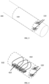
- FIG. 1 depicts apparatus 10 configured to stimulate tissue and comprising implantable system 110 and external system 100.
- this implant can be placed in different locations inside the body and can include a variety of systems.
- This implant can be either active or passive (e.g. include one or more active or passive components, respectfully), and the external equipment can consist of power transmission, data transmission, and/or magnetic field generation.
- the implantable systems 110 coupled with a single or multiple external systems 100.
- FIG. 2 A diagram of another tissue stimulating active implant system 200, according to another implementation, is shown in FIG. 2 .
- Active implant 200 can comprise a power source 210, which can include a power receiver and/or a power supply.
- the power source 210 can be either locally powered such as with batteries, capacitors, etc, and/or by harvesting energy from the body (heat, motion and/or chemical energy, for example) and/or remotely powered, such as with RF energy (near-, far-, or mid-field powering) or ultrasound.
- the controller 220 can be designed to work with existing devices, and can allow for either analog or digital control of the modulator, power systems, or other components. Controller 220 can also manage incoming data and communications with other systems.
- Implanted system 200 can comprise a tissue modulator 230, which can be surrounded by a housing (e.g. a sealing housing) surrounding at least a portion of tissue modulator 230.
- the modulator 230 can employ any of the active methods that are described herein, including conventional electrical methods and new methods for mechanical modulation as described herein.
- Modulator 230 may include an electromagnetic transducer such as a tranducer through which current flows, to generate a constant and/or varying magnetic field.
- Modulator 200 may include a magnetic transducer, such as a transducer comprising a passive magnet and/or an electromagnet.
- Modulator 230 may include an actuator that delivers mechanical force to tissue, such as an actuator selected from the group consisting of: a piezoelectric-based actuator; a thermal actuator; a motor; a linear actuator; a vibrating beam; and combinations of these.
- Modulator 230 may include an actuator that is controlled by varying one or more of: amplitude; frequency; duty cycle; and duration. Modulator 230 can be controlled by varying a magnetic field and/or by varying current.
- the implant portion of the system may perform any of a number of desired goals of diagnosis, therapy, or both.
- a major advantage of the implants described herein is that they are miniaturized and packaged such that they can be easily implanted using minimally invasive methods, such as via injection through a needle, for example, without the need for surgery, as shown in FIGS. 3 and 4 .
- the implant main body 310 can fit inside of a delivery needle or introducer 300.
- the implant main body 310 can also include one or more electrodes 320 that interface with the tissue or environment for modulation or sensing.
- the implant body 310 can also contain one or more fully enclosed antennas 410 and one or more integrated circuits 420 and other discrete passive or active components.
- the electrodes 320 can again interface with the tissue or environment.
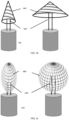
- the device itself can be completely contained in a non-deformable package or contain a rigid body with one or more extensions similar to 510 that can be made unfoldable, expandable, or detachable for form-factor or shape adaptation during or after the implantation procedure as shown in FIG. 5 and FIG. 6 .
- Methods for delivering different types of unfolding or expanding extensions are illustrated in 510, 610, 630, and 650.
- the flexible extensions 510, 610, 630, and 650 are illustrated in compact form on the left side and in expanded form on the right side of the figures.
- Some embodiments may include a rolled up extension which forms a rectangular antenna substrate 510, a parachute-like structure 610, an umbrella-like structure 630, and/or a spherical antenna structure 650.
- These structures may include printed conductor traces 520, 620, 640, and 660, which may form one or more planar loop, spiral, or dipole antennas when unfolded or inflated after implantation. For very small device sizes, the delivered power to the device can be very limited, especially for deeply implanted devices.
- the antenna may be beneficial to implement the antenna on a flexible substrate that can be folded (or rolled) in a way to make the device injectable with a needle.
- Examples of unfolding or expanding antennas are shown in 520, 620, 640, and 660.
- the antenna can be made to unfold (or unroll) such as to make its radar cross section (RCS) larger and thus increase the amount of power it can harvest.
- the antenna only or antenna together with the energy harvesting circuitry (such as matching network and rectifier) can be made separate from the rest of the implant in a form of unfolding extension. This would allow for the antenna to be closer to the tissue surface and therefore would reduce separation distance between the external transmitter and the implant antenna and would therefore potentially improve the link gain.
- FIG.5 and FIG.6 Some sketches for the implantation of various needle injectable devices are shown in FIG.5 and FIG.6 .
- the implant main body 310 may be positioned close to the surface of the tissue by first securing the electrodes at the desired location and then ejecting the device from the needle while the needle is being pulled back.
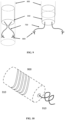
- the main body 310 can stay in the needle or injection device 300 while the wires or leads 700 are unraveling as the needle is being pulled back. This is illustrated in FIG. 7 . Then at the desired position, the remaining part of the implantable device can be ejected from the needle.
- the antenna can be unfolded or unrolled using inflation (e.g. via a fluid such as a gas, a liquid and/or a gel) and/or by incorporating spring-like structures into the antenna material, such that it naturally expands into the usable shape after it is ejected from the needle.
- inflation e.g. via a fluid such as a gas, a liquid and/or a gel
- the needle and the injection mechanism can have a small inflation tube 530 that is connected to the flexible antenna substrate.
- Electrodes 320 can be connected to the main body 310 as simple extensions and can further be made expandable after ejection from the needle. This can benefit the electrode configuration and placement, which can be adapted based on the needs of the application.
- the electrodes can be made from semi-rigid material and be fabricated such that they expand like a spring, tweezer-like element, or other expandable structure 700. Because of their flexibility, when placed inside the needle, they would naturally be compressed and therefore easily delivered with a desired separation. This process results in a larger separation than needle otherwise allows as shown in FIG. 7 .
- electrodes can include an anchor element 800, and can include a harpoon-shaped element 800; an arrow-shaped element 800; and/or threads, as shown in FIG. 8 and FIG. 9 .
- the barbed electrodes 800 puncture and attach to tissues and fix the device in place. These configurations would penetrate the desired tissue or organ and prevent it from being detached from it.
- the barbed electrodes 800 can also be used at the tip of the flexible electrodes 700 that expand upon delivery for better or more precise placement of the interface. This also allows for a simpler implantation procedure without any stitching or otherwise more complex attachment procedure.
- FIG. 10 Another possible attachment that allows for easy implantation is by incorporating a screw-like electrode on the device as shown in FIG. 10 .
- the screw electrode 910 screws into tissue to fix it in place.
- the screwing motion can be accomplished with threading 900 on the implant body 310 that has a matching thread on the delivery needle 300.
- the device can then screw into tissue for a better electrode-tissue interface and a secure attachment.
- Implant body 310 can contain a counter-electrode of opposite polarity to the active electrode 910 when electrode is being used to modulate tissue.
- the self-attaching structures 800 and 910) can simply be used to fixate the implant 310 to the target tissue.
- FIG. 11 shows a rigid surface 1000 and a bendable or pre-formed substrate 1010.
- the mechanism for wrapping this system around the target site 1020 is shown. This can be accomplished in several different ways, such as two sliding beams, with one beam (rigid beam 1000) staying in the delivery system 300 and the other (compliant beam 1010) bending around the site 1020 that needs to be treated or diagnosed.
- the rigid beam 1000 separates from the comformable beam 1010 and the comformable beam 1010 curves, naturally wrapping around target organ 1020.
- Another way is to compress a curved substrate 1010 into the needle that would serve as the rigid surface 1000, which would remain straight until ejected, and then would curve into a tight "ring" around the vein or artery as shown in FIG. 11 .
- This method of action would be substantially similar to a slap (snap) bracelet ("Slap Wrap").
- This method would contain a bi-stable spring which can be straightened out for delivery. The straightened bracelet cuff could then wrap around the target tissue 1020, forming a tight ring. This is caused by having the bi-stable spring transition into the second stable state (curved state), securing the implant 110 at the target site 320.
- the injection apparatus can consist of the main body 310 and a needle or introducer 300.
- the needle can be made rigid, flexible, or a combination to accommodate a particular implantation procedure. If it may be necessary to navigate around certain areas or organs, the bending or flexible needle can navigate around them and thus avoid certain locations within the body of tissue. This may also be beneficial if the implantable device needs to be positioned at a particular angle that is preferential over a straight line.
- an implantation procedure may involve: 1) injection of the needle or introducer 300 and its navigation to the implantation site; 2) initial ejection of the device 110 from the needle 300 until the electrodes are in contact with the stimulation site; 3a) if the device is fully contained without any extensions, then complete the delivery process of the device; 3b) if the device has one or more extensions, then proceed with retraction of the needle where the extension or the leads are unwinding at the same rate while the needle is being extracted (pulled back) from the implantation site; 4) if unfolding or unrolling of the extensions is necessary, proceed with the unfolding procedure once the unfolding extension (510, 610, 630, 650) is ejected from the needle; 5) once the device and all of the optional extensions are fully ejected, remove the needle or introducer 300.
- the injection device can further be used for extraction of the implant, if there may be a need.
- the needle or introducer 300 can be inserted and positioned to come in contact with the device and attach to it with suction forces.
- the extraction device can be used to extract the entire implant or a part of it, such as a particular extension. This can be done to replace or remove certain parts that can degrade or become unnecessary over time. In that case, the extensions can be made detachable if need be.
- Both injection and extraction of the implantable device can be guided using some sort of existing imaging modality from outside of the body of tissue, such as ultrasound, X-Ray, MRI, etc. Alternatively, it can be guided by optical fiber or a camera that can be placed at the tip of the injection needle. Furthermore, a technique similar to laparoscopy can be used for the implantation of the device. Conventional guidance methods such as catheters or non-invasive procedures may also be used.
- the implant can also be covered with biocompatible, bio-dissolvable, biodegradable materials.
- the electrodes may be encapsulated with a bio-dissolvable compound, which is present for ease of implantation, but is dissolved over a period of time post injection. Additionally or alternatively, the electrodes may be coated with drug eluting materials for proper adaptation and to minimize infection, inflammation, and rejection risks.
- the needle injectable implant can be packaged in a sterile needle and packaged together with a disposable injection device.
- the needle and the injection device may be similar to currently available needles and syringes and can be customized for a particular therapy application.
- Neuromodulation devices can require significant power to provide therapy, because of the relatively high voltage and current requirements needed to drive stimulation. Essentially, mechanical neuromodulation provides a more efficient conversion from electrical energy to therapeutic stimulation, and offers additional advantages in terms of safety and long-term use. Mechanically activating nerves can be accomplished with very small devices and with power-efficient mechanisms for generating force. Using electromagnetic forces allows for controllable stimulation with a fraction of the voltage and current requirements of electrical stimulation, and requires no direct electrical connection with tissue. This allows the device to be entirely encapsulated in bio-compatible materials if needed, and can therefore operate safely for extended periods of time.
- this actuation can be accomplished by generating a magnetic field to control a magnetic material, by controlling currents in a pre-existing magnetic field, or with some combination of the two.
- the force from these mechanical actuators can be applied directly to nerves or other tissues to activate them with similar characteristics as electrical stimulation, which results in similar therapeutic outcomes.
- This mechanical modulation system can be incorporated in the implant body 310 or it can be a separate extension as described. It can also be used in combination with sensors or other extensions, and it may be advantageous to have mechanical modulation operating in conjunction with electrical modulation.
- an electromagnet can be used to adjust the strength of the magnetic field.
- An effective way of accomplishing this is with several loops of wire around either a magnet or a magnetic material, similar to a solenoid.
- Current flows through the coil, inducing a magnetic field which applies a force to the magnet or magnetic material inside. This current can be oscillated to produce oscillating forces.
- the force on the magnetic material is given by F 1 and depends on the size of the material and its magnetization. Ferrite can have relative permeability ⁇ 1000, and mu-metals can have relative permeability of ⁇ 50,000 or more. Using a material with a high relative permeability allows for mm-sized and sub-mm devices to exert large enough forces to activate nerves. These devices can be electrically powered from an implantable device using 10-100x less power than direct electrical stimulation.
- the magnetic material in this method does not need to be located in the center of the coil, it only needs to be in range of the generated magnetic field to experience a force. Additionally, the restoring force can be supplied mechanically such as with a spring so that the electromechanical force is only exerted in one direction. This is especially useful if a magnetic material is used because the force is insensitive to the direction of the field, it is only sensitive to the gradient.
- An alternative method employs the forces exerted on current-carrying wires to actuate nerves.
- This method requires a magnetic field to be present, which can be provided from either a permanent magnet or an electromagnet, which can be either external or internal to the body.
- the force experienced by the wires is given by F 2 and is proportional to the magnetic field and the current. Additional wires can also be used to magnify the force.
- the current flowing in the wires can be controlled to precisely control the force on them, and several arrangements of wires can surround the nerves to apply a variety of forces to best activate the target nerve. These forces can squeeze, expand, push, or pull the nerve as needed. Several possible arrangements are shown in FIG. 15 .
- This figure shows wires that generate linear forces 1400, loops that experience compression or expansion forces 1410, and loops that experience torques 1420. These arrangements show how several types of forces and torques can be generated. A multitude of wire arrangements are possible, and the actuator can be designed for the targeted nerve with one or more of them.
- the current in the wires can oscillate with controlled parameters, such as frequency, amplitude, and duty cycle, to induce the desired mechanical forces.
- FIG. 12 An example of an implanted material experiencing forces due to F 1 and F 2 is shown in FIG. 12 .
- the magnetic field source/generator 1100 is outside of the body and induces forces on the implanted magnetic material 1110 or on current carrying wire arrangements 1120 through the use of magnetic fields. These forces can cause vibrations, rotations, or linear motion of the implanted material. If the material is attached or in the vicinity of targeted tissues, it can mechanically modulate them.
- FIG. 13 An example of an implanted material experiencing forces due to F 1 and F 2 using magnetic fields from an electromagnet is shown in FIG. 13 .
- the electromagnet 1200 is outside of the body and induces forces on the implanted magnetic material 1110 or on current carrying wire arrangements 1120 through the use of magnetic fields.
- the electromagnet 1200 includes coils of wire 1210 and an optional magnetic structure 1220 to enhance the generated field. These forces can cause vibrations, rotations, or linear motion of the implanted material 1110. If the material is attached or in the vicinity of targeted tissues, it can mechanically modulate them.
- the implant main body 310 or an extension may include a miniaturized electromagnet, as depicted in FIG. 14 .
- This electromagnet again consists of a smaller arrangement of coils of wire 1300 and a movable magnetic structure 1310.
- the field caused by currents flowing in the coils of wire 1300 induces forces on the magnetic structure 1310, causing it to move.
- the currents can be controlled to create controllable motion. These forces can cause vibrations that modulate surrounding tissues mechanically.
- Electromagnets can be enhanced with high permeability materials, which magnify the field strength.
- the forces must be designed to stimulate the nerves in a therapeutic way.
- a key advantage of electromagnetic methods is the ability to operate at a variety of frequencies and to have a highly adjustable force that operates effectively as the device is miniaturized.
- the stimulation can be optimized in terms of frequency, force, and duty cycle, simply by adjusting the flowing currents. For instance, some nerves are best stimulated with short bursts of high-frequency vibrations, while other nerves are best stimulated with one strong, high force pulse. In the case of fully wireless implants including battery-free, remotely powered devices, this means that the stimulation characteristics can be completely controlled externally with commands from the transmitter and have significant flexibility in operation. Additionally, the scalability of the forces allows for mm and sub-mm operation, allowing for use with devices that can be injected with a needle, placed with an endoscope, or placed with a catheter.
- the actual size of the actuators is determined by the needs of the application, as larger nerves may require more force for controlled stimulation. Some nerves, such as baroreceptors, are sensitive to the stretching of blood vessels, and so would require a mechanical structure to apply this type of force. Other nerves can be excited by localized tapping with certain parameters, and would require a different mechanical structure.
- the arrangements shown in FIG. 15 depict how these types of forces can be accomplished with the described actuators. From the force equations, it is clear that the described force actuation mechanisms have the power efficiency and scalability to meet the needs of these different applications, and the versatility to apply a variety of different forces at different sizes.
- these mechanical methods are easily integrated into existing devices, including fully wireless devices. They can also be implemented on a passive device, where the actuation is due to the manipulation of a magnetic structure with externally applied magnetic fields.
- the interface circuitry can be designed so that the stimulator controller is either analog or digital. Digital control offers simplicity and more universal operation, though analog control could be better optimized for increased power efficiency.
- the mechanical stimulators can operate with similar waveforms to that of electrical stimulators, and can therefore serve as a replacement with minimal alteration to existing devices. Additionally, these mechanical techniques can have significant advantages in terms of power efficiency and long-term safety because the tissue impedance does not impact performance and no electrical connection is required. Their high power-efficiency allows for use with remotely powered devices, which have a very limited power budget. This power efficiency would also prolong battery life for conventional devices. The level of miniaturization and efficiency also allows for entirely new devices which may be small enough for non-invasive implantation as previously discussed.
- these mechanisms When implanted in the body, these mechanisms can be packaged with epoxies or plastics that encapsulate it for bio-compatibility. These epoxies are ready available, and similar materials can be used to that of existing medical devices. Because no electrical connection is required, the device can be fully encapsulated and protected from the body without hindering performance. The forces will be experienced by the actuators regardless of the surrounding material, as common encapsulating materials are effectively transparent to electric and magnetic fields.
- Piezoelectric materials such as those shown in FIG. 16 , can apply large forces if they are needed, and can constructed in the form of vibrating beams, motors, linear actuators, or other vibrating structures designed with specific resonances. They operate when the piezoelectric 1500 has a voltage applied through an electrical contact 1510, thus inducing mechanical deformation. These devices can be efficient when operating at resonance, and can apply large forces though the forces get fairly weak as they are scaled down to mm-scales. Additionally, thermoelectric actuators could be useful for small devices and would not require the presence of a magnetic field.
Landscapes
- Health & Medical Sciences (AREA)
- Life Sciences & Earth Sciences (AREA)
- Veterinary Medicine (AREA)
- Public Health (AREA)
- General Health & Medical Sciences (AREA)
- Animal Behavior & Ethology (AREA)
- Engineering & Computer Science (AREA)
- Biomedical Technology (AREA)
- Nuclear Medicine, Radiotherapy & Molecular Imaging (AREA)
- Radiology & Medical Imaging (AREA)
- Heart & Thoracic Surgery (AREA)
- Neurology (AREA)
- Cardiology (AREA)
- Orthopedic Medicine & Surgery (AREA)
- Neurosurgery (AREA)
- Physics & Mathematics (AREA)
- Biophysics (AREA)
- Pathology (AREA)
- Medical Informatics (AREA)
- Molecular Biology (AREA)
- Surgery (AREA)
- Electrotherapy Devices (AREA)
- Prostheses (AREA)
Claims (15)
- Appareil médical destiné à s'interfacer avec un tissus d'un patient comprenant :un système implantable comprenant :une partie corps (310) destinée à être implantée à l'intérieur d'un patient,un élément ou une antenne de collecte d'énergie, etun circuit de collecte d'énergie,l'élément ou l'antenne de collecte d'énergie et le circuit de collecte d'énergie se présentant sous la forme d'une extension (510) fixée à la partie corps ;un système externe (100) qui transmet de manière transcutanée au moins une énergie ou des données au système implantable pendant son fonctionnement ; etun introducteur (300) pour introduire la partie corps (310) et l'au moins une extension (510) dans le patient ;le système implantable étant construit et agencé pour être posé par l'introducteur ; etl'extension (510) étant configurée pour passer d'un état compacté à un état étendu afin qu'une section transversale radar de l'élément ou de l'antenne de collecte d'énergie augmente la quantité d'énergie que ledit élément ou ladite antenne de collecte d'énergie peut collecter.
- Appareil médical selon la revendication 1, l'appareil médical étant configuré pour induire une réponse physiologique dans un tissu.
- Appareil médical selon la revendication 1 ou 2, l'appareil médical étant configuré pour surveiller l'activité tissulaire.
- Appareil médical selon l'une quelconque des revendications précédentes, le système externe (100) étant configuré pour transmettre de manière transcutanée de l'énergie et des données au système implantable pendant le fonctionnement.
- Appareil médical selon l'une quelconque des revendications précédentes, le système implantable réalisant une fonction sélectionnée dans le groupe constitué par : la fourniture d'énergie au tissu ; l'administration d'une thérapie au tissu ; l'administration d'un agent pharmaceutique au tissu ; la modulation du tissu ; la détection d'une activité physiologique ; la détection d'une activité neuronale ; la détection de conditions environnementales ; la détection de résultats thérapeutiques ; la détection de paramètres de thérapie administrée ; et des combinaisons de celles-ci.
- Appareil médical selon l'une quelconque des revendications précédentes, l'au moins une extension (510) comprenant un élément sélectionné dans le groupe constitué par : un fil ; une électrode ; une électrode adaptable ; deux faisceaux coulissants ; une électrode de brassard ; un élément d'ancrage ; un élément de stockage d'énergie ; et une combinaison de ceux-ci.
- Appareil médical selon l'une quelconque des revendications précédentes, le système implantable comprenant en outre un élément (230) sélectionné dans le groupe constitué par : un modulateur tissulaire ; un actionneur ; un actionneur électromagnétique ; un capteur ; et des combinaisons de ceux-ci.
- Appareil médical selon l'une quelconque des revendications précédentes, l'élément de collecte étant construit et agencé pour collecter l'énergie provenant du patient, l'énergie collectée comprenant l'énergie sélectionnée dans le groupe constitué par : une énergie thermique ; une énergie de mouvement ; une énergie chimique ; et des combinaisons de celles-ci.
- Appareil médical selon l'une quelconque des revendications précédentes, le système implantable comprenant un récepteur d'énergie (210) configuré pour recevoir de l'énergie sélectionnée dans le groupe constitué par : une énergie radiofréquence ; une énergie ultrasonique ; et des combinaisons de celles-ci.
- Appareil médical selon l'une quelconque des revendications précédentes, le système implantable comprenant en outre un élément de stockage d'énergie sélectionné dans le groupe constitué par : une batterie ; un condensateur ; et des combinaisons de ceux-ci.
- Appareil médical selon l'une quelconque des revendications précédentes, la transition de l'état dilaté comprenant un changement physique sélectionné dans le groupe constitué par : le dépliement ; le déroulement ; le déploiement ; et des combinaisons de ceux-ci.
- Appareil médical selon l'une quelconque des revendications précédentes, l'au moins une extension (510) comprenant une partie gonflable construite et agencée pour se dilater lorsqu'elle est remplie d'un fluide sélectionné dans le groupe constitué par : un gaz, un liquide, un gel, et des combinaisons de ceux-ci.
- Appareil médical selon l'une quelconque des revendications précédentes, l'au moins une extension comprenant un élément d'ancrage (800) sélectionné dans le groupe comprenant : des fils ; un élément en forme de flèche ; un élément en forme de harpon ; et des combinaisons de ceux-ci.
- Appareil médical selon l'une quelconque des revendications précédentes, l'au moins une extension (510) étant construite et agencée pour se détacher de la partie corps.
- Appareil médical selon l'une quelconque des revendications précédentes, l'introducteur (300) comprenant une canule souple et une canule rigide, et la canule souple étant construite et agencée pour recevoir de manière coulissante la canule rigide.
Applications Claiming Priority (3)
| Application Number | Priority Date | Filing Date | Title |
|---|---|---|---|
| US201361836544P | 2013-06-18 | 2013-06-18 | |
| US201361836536P | 2013-06-18 | 2013-06-18 | |
| PCT/US2014/043023 WO2014205129A1 (fr) | 2013-06-18 | 2014-06-18 | Procédé et appareil pour modulateurs implantables à invasion minimale |
Publications (3)
| Publication Number | Publication Date |
|---|---|
| EP3010581A1 EP3010581A1 (fr) | 2016-04-27 |
| EP3010581A4 EP3010581A4 (fr) | 2017-01-04 |
| EP3010581B1 true EP3010581B1 (fr) | 2023-10-11 |
Family
ID=52105246
Family Applications (1)
| Application Number | Title | Priority Date | Filing Date |
|---|---|---|---|
| EP14813206.1A Active EP3010581B1 (fr) | 2013-06-18 | 2014-06-18 | Appareil pour modulateurs implantables à invasion minimale |
Country Status (3)
| Country | Link |
|---|---|
| US (2) | US20160331956A1 (fr) |
| EP (1) | EP3010581B1 (fr) |
| WO (1) | WO2014205129A1 (fr) |
Families Citing this family (17)
| Publication number | Priority date | Publication date | Assignee | Title |
|---|---|---|---|---|
| EP3116385B1 (fr) | 2014-03-14 | 2019-11-06 | Nalu Medical, Inc. | Appareil pour neuromodulateurs polyvalents minimalement invasifs |
| WO2015196164A2 (fr) | 2014-06-21 | 2015-12-23 | Accelemed, Llc | Procédé et appareil de traitements de neuromodulation de la douleur et d'autres états |
| AU2015373055A1 (en) * | 2014-12-29 | 2017-08-10 | Ajoy I. Singh | A system and method for treating artery |
| EP3347085B1 (fr) | 2015-09-11 | 2023-07-26 | Nalu Medical, Inc. | Appareil de stimulation périphérique ou spinale |
| WO2017070372A1 (fr) | 2015-10-21 | 2017-04-27 | NeuSpera Medical Inc. | Dispositifs, systèmes et méthodes pour thérapie de stimulation |
| US20170214127A1 (en) * | 2016-01-26 | 2017-07-27 | Qualcomm Incorporated | Antenna deployment for medical implants |
| CA3014317A1 (fr) | 2016-02-19 | 2017-08-24 | Nalu Medical, Inc. | Appareil presentant des formes d'onde de stimulation amelioree |
| EP4395124A3 (fr) | 2016-03-21 | 2024-07-31 | Nalu Medical, Inc. | Dispositifs et procédés de positionnement de dispositifs externes par rapport à des dispositifs implantés |
| EP3463121B1 (fr) | 2016-05-25 | 2021-01-13 | Nalu Medical, Inc. | Systèmes pour l'insertion de dispositifs implantables |
| EP3484577A4 (fr) | 2016-07-18 | 2020-03-25 | Nalu Medical, Inc. | Procédés et systèmes de traitement de troubles pelviens et d'affections douloureuses |
| US20190290908A1 (en) | 2016-12-05 | 2019-09-26 | Autonomic Technologies, Inc. | Neurostimulators and related systems and methods |
| EP3562543B1 (fr) | 2016-12-30 | 2024-07-17 | Nalu Medical, Inc. | Appareil de stimulation |
| WO2018156953A1 (fr) | 2017-02-24 | 2018-08-30 | Nalu Medical, Inc. | Appareil avec stimulateurs implantés séquentiellement |
| WO2018208992A1 (fr) | 2017-05-09 | 2018-11-15 | Nalu Medical, Inc. | Appareil de stimulation |
| EP3769719A1 (fr) * | 2019-07-23 | 2021-01-27 | National University of Ireland Galway | Dispositif médical implantable |
| WO2023141568A1 (fr) * | 2022-01-20 | 2023-07-27 | University Of Notre Dame Du Lac | Systèmes et procédés de détection d'emplacements de structures tissulaires sous-cutanées |
| US20230369996A1 (en) * | 2022-05-15 | 2023-11-16 | Timm A. Vanderelli | Implantable Power Generator |
Citations (2)
| Publication number | Priority date | Publication date | Assignee | Title |
|---|---|---|---|---|
| EP2155330A1 (fr) * | 2007-04-17 | 2010-02-24 | Perpetuum Ltd. | Collecteur d'énergie destiné à un dispositif d'implantation |
| US20100249888A1 (en) * | 2008-07-06 | 2010-09-30 | Glenn Richard A | Intravascular implant anchors having remote communication and/or battery recharging capabilities |
Family Cites Families (31)
| Publication number | Priority date | Publication date | Assignee | Title |
|---|---|---|---|---|
| US5143067A (en) * | 1990-06-07 | 1992-09-01 | Medtronic, Inc. | Tool for implantable neural electrode |
| US7653438B2 (en) * | 2002-04-08 | 2010-01-26 | Ardian, Inc. | Methods and apparatus for renal neuromodulation |
| US8303511B2 (en) * | 2002-09-26 | 2012-11-06 | Pacesetter, Inc. | Implantable pressure transducer system optimized for reduced thrombosis effect |
| US20050033137A1 (en) * | 2002-10-25 | 2005-02-10 | The Regents Of The University Of Michigan | Ablation catheters and methods for their use |
| EP1633434B1 (fr) | 2003-06-04 | 2014-11-19 | Synecor | Systeme electrophysiologiques intravasculaires |
| US7082336B2 (en) | 2003-06-04 | 2006-07-25 | Synecor, Llc | Implantable intravascular device for defibrillation and/or pacing |
| US7245972B2 (en) * | 2004-04-29 | 2007-07-17 | Alfred E. Mann Foundation For Scientific Research | Electrical treatment to treat shoulder subluxation |
| US20060149330A1 (en) * | 2004-12-30 | 2006-07-06 | Brian Mann | Digitally controlled cardiac rhythm management |
| WO2007068284A1 (fr) * | 2005-12-12 | 2007-06-21 | Synergio Ag | Dispositif intracardiaque, système et procédés |
| US20070255368A1 (en) * | 2006-04-28 | 2007-11-01 | Bonde Eric H | Implantable medical electrical stimulation lead with distal fixation and method |
| US20070288076A1 (en) * | 2006-06-07 | 2007-12-13 | Cherik Bulkes | Biological tissue stimulator with flexible electrode carrier |
| EP2063766B1 (fr) * | 2006-09-06 | 2017-01-18 | Innurvation, Inc. | Dispositif capteur faible puissance ingérable et système de communication avec ce dispositif |
| US8688238B2 (en) * | 2006-10-31 | 2014-04-01 | Medtronic, Inc. | Implantable medical elongated member including fixation elements along an interior surface |
| US20080103578A1 (en) * | 2006-10-31 | 2008-05-01 | Medtronic, Inc. | Implantable medical elongated member with in situ formed fixation element |
| US7765012B2 (en) * | 2006-11-30 | 2010-07-27 | Medtronic, Inc. | Implantable medical device including a conductive fixation element |
| US8805530B2 (en) * | 2007-06-01 | 2014-08-12 | Witricity Corporation | Power generation for implantable devices |
| WO2009099550A1 (fr) | 2008-02-07 | 2009-08-13 | Cardiac Pacemakers, Inc. | Électrostimulation tissulaire sans fil |
| US8588926B2 (en) * | 2008-03-25 | 2013-11-19 | Ebr Systems, Inc. | Implantable wireless accoustic stimulators with high energy conversion efficiencies |
| EP2197539A1 (fr) * | 2008-04-30 | 2010-06-23 | Medtronic, Inc. | Techniques de placement de dérivations médicales pour la stimulation électrique d'un tissu nerveux |
| CA2787062C (fr) * | 2010-01-26 | 2017-07-11 | Michael A. Evans | Procedes, dispositifs, et agents de denervation |
| US8788045B2 (en) | 2010-06-08 | 2014-07-22 | Bluewind Medical Ltd. | Tibial nerve stimulation |
| US8909316B2 (en) * | 2011-05-18 | 2014-12-09 | St. Jude Medical, Cardiology Division, Inc. | Apparatus and method of assessing transvascular denervation |
| WO2013035092A2 (fr) * | 2011-09-09 | 2013-03-14 | Enopace Biomedical Ltd. | Électrodes basées sur un stent endovasculaire sans fil |
| US9446255B2 (en) * | 2011-11-13 | 2016-09-20 | Arizona Board of Regents on Behalf Arizona State University | Controlled stimulation delivery from neurostimulator |
| US20130215979A1 (en) | 2012-01-04 | 2013-08-22 | The Board Of Trustees Of The Leland Stanford Junior University | Method and Apparatus for Efficient Communication with Implantable Devices |
| WO2013111137A2 (fr) * | 2012-01-26 | 2013-08-01 | Rainbow Medical Ltd. | Neurostimulateurs sans fil |
| JP6159346B2 (ja) * | 2012-02-17 | 2017-07-05 | ユニバーシティ オブ ヴァージニア パテント ファウンデーション | 環境発電及びセンサノードの制御 |
| EP2852339B1 (fr) * | 2012-05-29 | 2020-12-23 | Autonomix Medical, Inc. | Systèmes de sympathectomie endoscopiques |
| AU2013274158B2 (en) * | 2012-06-14 | 2018-05-10 | Autonomix Medical, Inc. | Devices, systems, and methods for diagnosis and treatment of overactive bladder |
| US9095700B2 (en) * | 2012-08-10 | 2015-08-04 | Greatbach Ltd. | Lead positioning and fixation system |
| US10994149B2 (en) * | 2013-03-14 | 2021-05-04 | Stimwave Technologies Incorporated | Wireless implantable power receiver system and methods |
-
2014
- 2014-06-18 WO PCT/US2014/043023 patent/WO2014205129A1/fr active Application Filing
- 2014-06-18 EP EP14813206.1A patent/EP3010581B1/fr active Active
-
2015
- 2015-12-18 US US14/975,358 patent/US20160331956A1/en not_active Abandoned
-
2021
- 2021-04-26 US US17/240,629 patent/US20220072300A1/en active Pending
Patent Citations (2)
| Publication number | Priority date | Publication date | Assignee | Title |
|---|---|---|---|---|
| EP2155330A1 (fr) * | 2007-04-17 | 2010-02-24 | Perpetuum Ltd. | Collecteur d'énergie destiné à un dispositif d'implantation |
| US20100249888A1 (en) * | 2008-07-06 | 2010-09-30 | Glenn Richard A | Intravascular implant anchors having remote communication and/or battery recharging capabilities |
Also Published As
| Publication number | Publication date |
|---|---|
| EP3010581A4 (fr) | 2017-01-04 |
| EP3010581A1 (fr) | 2016-04-27 |
| US20220072300A1 (en) | 2022-03-10 |
| US20160331956A1 (en) | 2016-11-17 |
| WO2014205129A1 (fr) | 2014-12-24 |
Similar Documents
| Publication | Publication Date | Title |
|---|---|---|
| US20220072300A1 (en) | Method and apparatus for minimally invasive implantable modulators | |
| US12059571B2 (en) | Wireless neurostimulators | |
| US10363419B2 (en) | Nerve stimulator system | |
| JP6522047B2 (ja) | ドライアイを治療するためのシステムおよび方法 | |
| JP5554062B2 (ja) | 心臓血管機能を調節する埋込型神経刺激装置 | |
| JP2019205835A (ja) | 電磁エネルギー生成のための多素子カプラ | |
| WO2005118057A2 (fr) | Outil de prise pour dispositifs medicaux implantables | |
| US20080195188A1 (en) | Implantable medical device with fixation mechanism | |
| US9095700B2 (en) | Lead positioning and fixation system | |
| US20220387812A1 (en) | Device for, and method of, neuromodulation with closed-loop micromagnetic hybrid waveforms to relieve pain | |
| CN215025235U (zh) | 一种脊髓神经刺激器 | |
| CN116159244B (zh) | 一种注射式微型神经刺激器及神经刺激系统 | |
| KR20180048843A (ko) | 전기치료 시스템, 기기 및 방법 | |
| WO2012150348A1 (fr) | Dispositif pour la stimulation électrique d'un corps et/ou d'un site neurologique | |
| WO2024171121A1 (fr) | Systèmes de stimulation électrique avec stimulateur déformable et procédés associés | |
| WO2024023719A1 (fr) | Systèmes de stimulation électrique alimentés sans fil et procédés associés | |
| AU2024202249A1 (en) | Device for, and method of, neuromodulation with closed-loop micromagnetic hybrid waveforms to relieve pain | |
| JP2012157493A (ja) | 電気刺激装置 | |
| JP2012161496A (ja) | リード組立体、電気刺激装置およびリード | |
| WO2013047015A1 (fr) | Moyen de fixation de sondes et dispositif médical | |
| WO2012026202A1 (fr) | Dispositif de stimulation électrique et fil d'électrode | |
| WO2009048377A1 (fr) | Procédé d'aide à la circulation dans le coeur |
Legal Events
| Date | Code | Title | Description |
|---|---|---|---|
| PUAI | Public reference made under article 153(3) epc to a published international application that has entered the european phase |
Free format text: ORIGINAL CODE: 0009012 |
|
| 17P | Request for examination filed |
Effective date: 20160118 |
|
| AK | Designated contracting states |
Kind code of ref document: A1 Designated state(s): AL AT BE BG CH CY CZ DE DK EE ES FI FR GB GR HR HU IE IS IT LI LT LU LV MC MK MT NL NO PL PT RO RS SE SI SK SM TR |
|
| AX | Request for extension of the european patent |
Extension state: BA ME |
|
| DAX | Request for extension of the european patent (deleted) | ||
| A4 | Supplementary search report drawn up and despatched |
Effective date: 20161206 |
|
| RIC1 | Information provided on ipc code assigned before grant |
Ipc: A61N 1/05 20060101AFI20161130BHEP Ipc: A61N 1/372 20060101ALI20161130BHEP Ipc: A61N 7/00 20060101ALI20161130BHEP Ipc: A61B 5/04 20060101ALI20161130BHEP |
|
| RAP1 | Party data changed (applicant data changed or rights of an application transferred) |
Owner name: NALU MEDICAL, INC. |
|
| STAA | Information on the status of an ep patent application or granted ep patent |
Free format text: STATUS: EXAMINATION IS IN PROGRESS |
|
| 17Q | First examination report despatched |
Effective date: 20181120 |
|
| RAP1 | Party data changed (applicant data changed or rights of an application transferred) |
Owner name: NALU MEDICAL, INC. |
|
| STAA | Information on the status of an ep patent application or granted ep patent |
Free format text: STATUS: EXAMINATION IS IN PROGRESS |
|
| STAA | Information on the status of an ep patent application or granted ep patent |
Free format text: STATUS: EXAMINATION IS IN PROGRESS |
|
| GRAP | Despatch of communication of intention to grant a patent |
Free format text: ORIGINAL CODE: EPIDOSNIGR1 |
|
| STAA | Information on the status of an ep patent application or granted ep patent |
Free format text: STATUS: GRANT OF PATENT IS INTENDED |
|
| RIC1 | Information provided on ipc code assigned before grant |
Ipc: A61N 1/372 20060101ALI20221107BHEP Ipc: A61N 7/00 20060101ALI20221107BHEP Ipc: A61N 1/05 20060101AFI20221107BHEP |
|
| INTG | Intention to grant announced |
Effective date: 20221128 |
|
| GRAJ | Information related to disapproval of communication of intention to grant by the applicant or resumption of examination proceedings by the epo deleted |
Free format text: ORIGINAL CODE: EPIDOSDIGR1 |
|
| STAA | Information on the status of an ep patent application or granted ep patent |
Free format text: STATUS: EXAMINATION IS IN PROGRESS |
|
| GRAP | Despatch of communication of intention to grant a patent |
Free format text: ORIGINAL CODE: EPIDOSNIGR1 |
|
| STAA | Information on the status of an ep patent application or granted ep patent |
Free format text: STATUS: GRANT OF PATENT IS INTENDED |
|
| INTC | Intention to grant announced (deleted) | ||
| INTG | Intention to grant announced |
Effective date: 20230503 |
|
| P01 | Opt-out of the competence of the unified patent court (upc) registered |
Effective date: 20230427 |
|
| GRAS | Grant fee paid |
Free format text: ORIGINAL CODE: EPIDOSNIGR3 |
|
| GRAA | (expected) grant |
Free format text: ORIGINAL CODE: 0009210 |
|
| STAA | Information on the status of an ep patent application or granted ep patent |
Free format text: STATUS: THE PATENT HAS BEEN GRANTED |
|
| AK | Designated contracting states |
Kind code of ref document: B1 Designated state(s): AL AT BE BG CH CY CZ DE DK EE ES FI FR GB GR HR HU IE IS IT LI LT LU LV MC MK MT NL NO PL PT RO RS SE SI SK SM TR |
|
| REG | Reference to a national code |
Ref country code: GB Ref legal event code: FG4D |
|
| REG | Reference to a national code |
Ref country code: CH Ref legal event code: EP |
|
| REG | Reference to a national code |
Ref country code: DE Ref legal event code: R096 Ref document number: 602014088571 Country of ref document: DE |
|
| REG | Reference to a national code |
Ref country code: IE Ref legal event code: FG4D |
|
| REG | Reference to a national code |
Ref country code: LT Ref legal event code: MG9D |
|
| REG | Reference to a national code |
Ref country code: NL Ref legal event code: MP Effective date: 20231011 |
|
| REG | Reference to a national code |
Ref country code: AT Ref legal event code: MK05 Ref document number: 1619612 Country of ref document: AT Kind code of ref document: T Effective date: 20231011 |
|
| PG25 | Lapsed in a contracting state [announced via postgrant information from national office to epo] |
Ref country code: NL Free format text: LAPSE BECAUSE OF FAILURE TO SUBMIT A TRANSLATION OF THE DESCRIPTION OR TO PAY THE FEE WITHIN THE PRESCRIBED TIME-LIMIT Effective date: 20231011 |
|
| PG25 | Lapsed in a contracting state [announced via postgrant information from national office to epo] |
Ref country code: GR Free format text: LAPSE BECAUSE OF FAILURE TO SUBMIT A TRANSLATION OF THE DESCRIPTION OR TO PAY THE FEE WITHIN THE PRESCRIBED TIME-LIMIT Effective date: 20240112 |
|
| PG25 | Lapsed in a contracting state [announced via postgrant information from national office to epo] |
Ref country code: IS Free format text: LAPSE BECAUSE OF FAILURE TO SUBMIT A TRANSLATION OF THE DESCRIPTION OR TO PAY THE FEE WITHIN THE PRESCRIBED TIME-LIMIT Effective date: 20240211 |
|
| PG25 | Lapsed in a contracting state [announced via postgrant information from national office to epo] |
Ref country code: LT Free format text: LAPSE BECAUSE OF FAILURE TO SUBMIT A TRANSLATION OF THE DESCRIPTION OR TO PAY THE FEE WITHIN THE PRESCRIBED TIME-LIMIT Effective date: 20231011 |
|
| PG25 | Lapsed in a contracting state [announced via postgrant information from national office to epo] |
Ref country code: AT Free format text: LAPSE BECAUSE OF FAILURE TO SUBMIT A TRANSLATION OF THE DESCRIPTION OR TO PAY THE FEE WITHIN THE PRESCRIBED TIME-LIMIT Effective date: 20231011 |
|
| PG25 | Lapsed in a contracting state [announced via postgrant information from national office to epo] |
Ref country code: ES Free format text: LAPSE BECAUSE OF FAILURE TO SUBMIT A TRANSLATION OF THE DESCRIPTION OR TO PAY THE FEE WITHIN THE PRESCRIBED TIME-LIMIT Effective date: 20231011 |
|
| PG25 | Lapsed in a contracting state [announced via postgrant information from national office to epo] |
Ref country code: LT Free format text: LAPSE BECAUSE OF FAILURE TO SUBMIT A TRANSLATION OF THE DESCRIPTION OR TO PAY THE FEE WITHIN THE PRESCRIBED TIME-LIMIT Effective date: 20231011 Ref country code: IS Free format text: LAPSE BECAUSE OF FAILURE TO SUBMIT A TRANSLATION OF THE DESCRIPTION OR TO PAY THE FEE WITHIN THE PRESCRIBED TIME-LIMIT Effective date: 20240211 Ref country code: GR Free format text: LAPSE BECAUSE OF FAILURE TO SUBMIT A TRANSLATION OF THE DESCRIPTION OR TO PAY THE FEE WITHIN THE PRESCRIBED TIME-LIMIT Effective date: 20240112 Ref country code: ES Free format text: LAPSE BECAUSE OF FAILURE TO SUBMIT A TRANSLATION OF THE DESCRIPTION OR TO PAY THE FEE WITHIN THE PRESCRIBED TIME-LIMIT Effective date: 20231011 Ref country code: BG Free format text: LAPSE BECAUSE OF FAILURE TO SUBMIT A TRANSLATION OF THE DESCRIPTION OR TO PAY THE FEE WITHIN THE PRESCRIBED TIME-LIMIT Effective date: 20240111 Ref country code: AT Free format text: LAPSE BECAUSE OF FAILURE TO SUBMIT A TRANSLATION OF THE DESCRIPTION OR TO PAY THE FEE WITHIN THE PRESCRIBED TIME-LIMIT Effective date: 20231011 Ref country code: PT Free format text: LAPSE BECAUSE OF FAILURE TO SUBMIT A TRANSLATION OF THE DESCRIPTION OR TO PAY THE FEE WITHIN THE PRESCRIBED TIME-LIMIT Effective date: 20240212 |
|
| PG25 | Lapsed in a contracting state [announced via postgrant information from national office to epo] |
Ref country code: SE Free format text: LAPSE BECAUSE OF FAILURE TO SUBMIT A TRANSLATION OF THE DESCRIPTION OR TO PAY THE FEE WITHIN THE PRESCRIBED TIME-LIMIT Effective date: 20231011 Ref country code: RS Free format text: LAPSE BECAUSE OF FAILURE TO SUBMIT A TRANSLATION OF THE DESCRIPTION OR TO PAY THE FEE WITHIN THE PRESCRIBED TIME-LIMIT Effective date: 20231011 Ref country code: PL Free format text: LAPSE BECAUSE OF FAILURE TO SUBMIT A TRANSLATION OF THE DESCRIPTION OR TO PAY THE FEE WITHIN THE PRESCRIBED TIME-LIMIT Effective date: 20231011 Ref country code: NO Free format text: LAPSE BECAUSE OF FAILURE TO SUBMIT A TRANSLATION OF THE DESCRIPTION OR TO PAY THE FEE WITHIN THE PRESCRIBED TIME-LIMIT Effective date: 20240111 Ref country code: LV Free format text: LAPSE BECAUSE OF FAILURE TO SUBMIT A TRANSLATION OF THE DESCRIPTION OR TO PAY THE FEE WITHIN THE PRESCRIBED TIME-LIMIT Effective date: 20231011 Ref country code: HR Free format text: LAPSE BECAUSE OF FAILURE TO SUBMIT A TRANSLATION OF THE DESCRIPTION OR TO PAY THE FEE WITHIN THE PRESCRIBED TIME-LIMIT Effective date: 20231011 |
|
| PGFP | Annual fee paid to national office [announced via postgrant information from national office to epo] |
Ref country code: GB Payment date: 20240624 Year of fee payment: 11 |
|
| PGFP | Annual fee paid to national office [announced via postgrant information from national office to epo] |
Ref country code: DE Payment date: 20240621 Year of fee payment: 11 |
|
| PG25 | Lapsed in a contracting state [announced via postgrant information from national office to epo] |
Ref country code: DK Free format text: LAPSE BECAUSE OF FAILURE TO SUBMIT A TRANSLATION OF THE DESCRIPTION OR TO PAY THE FEE WITHIN THE PRESCRIBED TIME-LIMIT Effective date: 20231011 |
|
| REG | Reference to a national code |
Ref country code: DE Ref legal event code: R097 Ref document number: 602014088571 Country of ref document: DE |
|
| PG25 | Lapsed in a contracting state [announced via postgrant information from national office to epo] |
Ref country code: CZ Free format text: LAPSE BECAUSE OF FAILURE TO SUBMIT A TRANSLATION OF THE DESCRIPTION OR TO PAY THE FEE WITHIN THE PRESCRIBED TIME-LIMIT Effective date: 20231011 |
|
| PG25 | Lapsed in a contracting state [announced via postgrant information from national office to epo] |
Ref country code: SK Free format text: LAPSE BECAUSE OF FAILURE TO SUBMIT A TRANSLATION OF THE DESCRIPTION OR TO PAY THE FEE WITHIN THE PRESCRIBED TIME-LIMIT Effective date: 20231011 |
|
| PG25 | Lapsed in a contracting state [announced via postgrant information from national office to epo] |
Ref country code: SM Free format text: LAPSE BECAUSE OF FAILURE TO SUBMIT A TRANSLATION OF THE DESCRIPTION OR TO PAY THE FEE WITHIN THE PRESCRIBED TIME-LIMIT Effective date: 20231011 Ref country code: SK Free format text: LAPSE BECAUSE OF FAILURE TO SUBMIT A TRANSLATION OF THE DESCRIPTION OR TO PAY THE FEE WITHIN THE PRESCRIBED TIME-LIMIT Effective date: 20231011 Ref country code: RO Free format text: LAPSE BECAUSE OF FAILURE TO SUBMIT A TRANSLATION OF THE DESCRIPTION OR TO PAY THE FEE WITHIN THE PRESCRIBED TIME-LIMIT Effective date: 20231011 Ref country code: IT Free format text: LAPSE BECAUSE OF FAILURE TO SUBMIT A TRANSLATION OF THE DESCRIPTION OR TO PAY THE FEE WITHIN THE PRESCRIBED TIME-LIMIT Effective date: 20231011 Ref country code: EE Free format text: LAPSE BECAUSE OF FAILURE TO SUBMIT A TRANSLATION OF THE DESCRIPTION OR TO PAY THE FEE WITHIN THE PRESCRIBED TIME-LIMIT Effective date: 20231011 Ref country code: DK Free format text: LAPSE BECAUSE OF FAILURE TO SUBMIT A TRANSLATION OF THE DESCRIPTION OR TO PAY THE FEE WITHIN THE PRESCRIBED TIME-LIMIT Effective date: 20231011 Ref country code: CZ Free format text: LAPSE BECAUSE OF FAILURE TO SUBMIT A TRANSLATION OF THE DESCRIPTION OR TO PAY THE FEE WITHIN THE PRESCRIBED TIME-LIMIT Effective date: 20231011 |
|
| PLBE | No opposition filed within time limit |
Free format text: ORIGINAL CODE: 0009261 |
|
| STAA | Information on the status of an ep patent application or granted ep patent |
Free format text: STATUS: NO OPPOSITION FILED WITHIN TIME LIMIT |
|
| 26N | No opposition filed |
Effective date: 20240712 |
|
| PG25 | Lapsed in a contracting state [announced via postgrant information from national office to epo] |
Ref country code: SI Free format text: LAPSE BECAUSE OF FAILURE TO SUBMIT A TRANSLATION OF THE DESCRIPTION OR TO PAY THE FEE WITHIN THE PRESCRIBED TIME-LIMIT Effective date: 20231011 |
|
| PG25 | Lapsed in a contracting state [announced via postgrant information from national office to epo] |
Ref country code: SI Free format text: LAPSE BECAUSE OF FAILURE TO SUBMIT A TRANSLATION OF THE DESCRIPTION OR TO PAY THE FEE WITHIN THE PRESCRIBED TIME-LIMIT Effective date: 20231011 |