EP3010564B1 - Artificial ventricles - Google Patents
Artificial ventricles Download PDFInfo
- Publication number
- EP3010564B1 EP3010564B1 EP14813602.1A EP14813602A EP3010564B1 EP 3010564 B1 EP3010564 B1 EP 3010564B1 EP 14813602 A EP14813602 A EP 14813602A EP 3010564 B1 EP3010564 B1 EP 3010564B1
- Authority
- EP
- European Patent Office
- Prior art keywords
- magnetic field
- chamber
- field generator
- artificial ventricle
- wall
- Prior art date
- Legal status (The legal status is an assumption and is not a legal conclusion. Google has not performed a legal analysis and makes no representation as to the accuracy of the status listed.)
- Active
Links
Images


Classifications
-
- A—HUMAN NECESSITIES
- A61—MEDICAL OR VETERINARY SCIENCE; HYGIENE
- A61M—DEVICES FOR INTRODUCING MEDIA INTO, OR ONTO, THE BODY; DEVICES FOR TRANSDUCING BODY MEDIA OR FOR TAKING MEDIA FROM THE BODY; DEVICES FOR PRODUCING OR ENDING SLEEP OR STUPOR
- A61M60/00—Blood pumps; Devices for mechanical circulatory actuation; Balloon pumps for circulatory assistance
- A61M60/80—Constructional details other than related to driving
- A61M60/855—Constructional details other than related to driving of implantable pumps or pumping devices
- A61M60/89—Valves
- A61M60/892—Active valves, i.e. actuated by an external force
-
- A—HUMAN NECESSITIES
- A61—MEDICAL OR VETERINARY SCIENCE; HYGIENE
- A61M—DEVICES FOR INTRODUCING MEDIA INTO, OR ONTO, THE BODY; DEVICES FOR TRANSDUCING BODY MEDIA OR FOR TAKING MEDIA FROM THE BODY; DEVICES FOR PRODUCING OR ENDING SLEEP OR STUPOR
- A61M60/00—Blood pumps; Devices for mechanical circulatory actuation; Balloon pumps for circulatory assistance
- A61M60/20—Type thereof
- A61M60/247—Positive displacement blood pumps
- A61M60/253—Positive displacement blood pumps including a displacement member directly acting on the blood
- A61M60/268—Positive displacement blood pumps including a displacement member directly acting on the blood the displacement member being flexible, e.g. membranes, diaphragms or bladders
-
- A—HUMAN NECESSITIES
- A61—MEDICAL OR VETERINARY SCIENCE; HYGIENE
- A61M—DEVICES FOR INTRODUCING MEDIA INTO, OR ONTO, THE BODY; DEVICES FOR TRANSDUCING BODY MEDIA OR FOR TAKING MEDIA FROM THE BODY; DEVICES FOR PRODUCING OR ENDING SLEEP OR STUPOR
- A61M60/00—Blood pumps; Devices for mechanical circulatory actuation; Balloon pumps for circulatory assistance
- A61M60/10—Location thereof with respect to the patient's body
- A61M60/122—Implantable pumps or pumping devices, i.e. the blood being pumped inside the patient's body
- A61M60/165—Implantable pumps or pumping devices, i.e. the blood being pumped inside the patient's body implantable in, on, or around the heart
- A61M60/178—Implantable pumps or pumping devices, i.e. the blood being pumped inside the patient's body implantable in, on, or around the heart drawing blood from a ventricle and returning the blood to the arterial system via a cannula external to the ventricle, e.g. left or right ventricular assist devices
-
- A—HUMAN NECESSITIES
- A61—MEDICAL OR VETERINARY SCIENCE; HYGIENE
- A61M—DEVICES FOR INTRODUCING MEDIA INTO, OR ONTO, THE BODY; DEVICES FOR TRANSDUCING BODY MEDIA OR FOR TAKING MEDIA FROM THE BODY; DEVICES FOR PRODUCING OR ENDING SLEEP OR STUPOR
- A61M60/00—Blood pumps; Devices for mechanical circulatory actuation; Balloon pumps for circulatory assistance
- A61M60/40—Details relating to driving
- A61M60/424—Details relating to driving for positive displacement blood pumps
- A61M60/457—Details relating to driving for positive displacement blood pumps the force acting on the blood contacting member being magnetic
- A61M60/462—Electromagnetic force
-
- A—HUMAN NECESSITIES
- A61—MEDICAL OR VETERINARY SCIENCE; HYGIENE
- A61M—DEVICES FOR INTRODUCING MEDIA INTO, OR ONTO, THE BODY; DEVICES FOR TRANSDUCING BODY MEDIA OR FOR TAKING MEDIA FROM THE BODY; DEVICES FOR PRODUCING OR ENDING SLEEP OR STUPOR
- A61M60/00—Blood pumps; Devices for mechanical circulatory actuation; Balloon pumps for circulatory assistance
- A61M60/50—Details relating to control
- A61M60/508—Electronic control means, e.g. for feedback regulation
- A61M60/515—Regulation using real-time patient data
-
- A—HUMAN NECESSITIES
- A61—MEDICAL OR VETERINARY SCIENCE; HYGIENE
- A61M—DEVICES FOR INTRODUCING MEDIA INTO, OR ONTO, THE BODY; DEVICES FOR TRANSDUCING BODY MEDIA OR FOR TAKING MEDIA FROM THE BODY; DEVICES FOR PRODUCING OR ENDING SLEEP OR STUPOR
- A61M60/00—Blood pumps; Devices for mechanical circulatory actuation; Balloon pumps for circulatory assistance
- A61M60/80—Constructional details other than related to driving
- A61M60/855—Constructional details other than related to driving of implantable pumps or pumping devices
- A61M60/89—Valves
- A61M60/894—Passive valves, i.e. valves actuated by the blood
- A61M60/896—Passive valves, i.e. valves actuated by the blood having flexible or resilient parts, e.g. flap valves
-
- A—HUMAN NECESSITIES
- A61—MEDICAL OR VETERINARY SCIENCE; HYGIENE
- A61M—DEVICES FOR INTRODUCING MEDIA INTO, OR ONTO, THE BODY; DEVICES FOR TRANSDUCING BODY MEDIA OR FOR TAKING MEDIA FROM THE BODY; DEVICES FOR PRODUCING OR ENDING SLEEP OR STUPOR
- A61M2230/00—Measuring parameters of the user
- A61M2230/005—Parameter used as control input for the apparatus
-
- A—HUMAN NECESSITIES
- A61—MEDICAL OR VETERINARY SCIENCE; HYGIENE
- A61M—DEVICES FOR INTRODUCING MEDIA INTO, OR ONTO, THE BODY; DEVICES FOR TRANSDUCING BODY MEDIA OR FOR TAKING MEDIA FROM THE BODY; DEVICES FOR PRODUCING OR ENDING SLEEP OR STUPOR
- A61M2230/00—Measuring parameters of the user
- A61M2230/04—Heartbeat characteristics, e.g. ECG, blood pressure modulation
-
- A—HUMAN NECESSITIES
- A61—MEDICAL OR VETERINARY SCIENCE; HYGIENE
- A61M—DEVICES FOR INTRODUCING MEDIA INTO, OR ONTO, THE BODY; DEVICES FOR TRANSDUCING BODY MEDIA OR FOR TAKING MEDIA FROM THE BODY; DEVICES FOR PRODUCING OR ENDING SLEEP OR STUPOR
- A61M60/00—Blood pumps; Devices for mechanical circulatory actuation; Balloon pumps for circulatory assistance
- A61M60/10—Location thereof with respect to the patient's body
- A61M60/122—Implantable pumps or pumping devices, i.e. the blood being pumped inside the patient's body
- A61M60/126—Implantable pumps or pumping devices, i.e. the blood being pumped inside the patient's body implantable via, into, inside, in line, branching on, or around a blood vessel
- A61M60/148—Implantable pumps or pumping devices, i.e. the blood being pumped inside the patient's body implantable via, into, inside, in line, branching on, or around a blood vessel in line with a blood vessel using resection or like techniques, e.g. permanent endovascular heart assist devices
Definitions
- the present invention relates to ventricular assist devices and, in particular, to implantable artificial ventricles (eg. see US3768931 ).
- intra-aortic balloon pumps operating in counterpulsation, to assist heart function.
- intra-aortic balloon pumps may be insufficient to sustain hemodynamics if the left heart is severely injured.
- United States Patent Number 7,347,811 which issued on March 25, 2008 to Peters et al. . discloses a device for providing counter-pulsation heart assist by deforming the aorta.
- the deformation pressure is applied cyclically, preferably in synchrony with the diastolic period of the heart.
- the deformation pressure may be applied to the outer wall of the aorta or to a patch covering a resected opening in the wall of the aorta.
- an artificial ventricle comprising an inlet for receiving blood, an outlet for discharging blood, and a chamber disposed between the inlet and the outlet. There is also a mechanism for actuating the artificial ventricle between an expanded configuration and a contracted configuration. In the expanded configuration blood flows into the inlet. In the contracted configuration blood flows out of the outlet. There may be a one-way valve at the outlet for preventing blood flow back into the chamber. The one-way valve may be a diaphragm valve.
- the chamber may have a resilient outer wall. The chamber may have an ovoid shape.
- the mechanism for actuating the artificial ventricle between the expanded configuration and the contracted configuration may include a first pad disposed on the resilient outer wall of the chamber and a second pad disposed on the resilient outer wall of the chamber opposite of the first pad.
- the first pad may have a magnetic field generator and the second pad may have a material which is attracted to the magnetic field generator when the magnetic field generator generates a magnetic field.
- the second pad may move towards the first pad when the magnetic field generator generates a magnetic field, and thereby actuate the artificial ventricle to the contracted configuration by contracting the resilient outer wall of the chamber.
- the resilient outer wall of the chamber may actuate the artificial ventricle to the expanded configuration when the magnetic field generator is not generating a magnetic field and the material is not attracted to the magnetic field generator.
- the mechanism for actuating the artificial ventricle between the expanded configuration and the contracted configuration may alternatively include a magnetic field generator integral with the resilient outer wall of the chamber and a material integral with the resilient outer wall of the chamber which is attracted to the magnetic field generator when the magnetic field generator generates a magnetic field.
- the material may move toward the magnetic field generator when the magnetic field generator generates a magnetic field and thereby actuate the artificial ventricle to the contracted configuration by contracting the resilient outer wall of the chamber.
- the resilient outer wall of the chamber may actuate the artificial ventricle to the expanded configuration when the magnetic field generator is not generating a magnetic field and the material is not attracted to the magnetic field generator.
- the artificial ventricle may further include an electrical energy supply electrically connected to the magnetic field generator, a controller which drives the electric energy supply to either energize or de-energize the magnetic field generator, and an ECG signal generator which signals the controller when there is ventricular diastole and ventricular systole.
- the controller may drive the electrical energy supply to energize the magnetic field generator when the ECG signal generator signals the controller that there is ventricular diastole.
- the controller may drive the electrical energy supply to de-energize the magnetic field generator when the ECG signal generator signals the controller that there is ventricular systole.
- a method of left ventricle assist comprising removing a portion of the aorta distal of the native aortic valve and implanting an artificial ventricle to replace the removed portion of the aorta.
- the artificial ventricle comprises an inlet for receiving blood, an outlet for discharging blood, and a chamber disposed between the inlet and the outlet.
- the artificial ventricle is actuated to the expanded configuration during ventricular systole and the artificial ventricle is actuated to the contracted configuration during ventricular diastole.
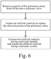
- a method of right ventricle assist comprising removing a portion of the pulmonary artery distal of the native pulmonic valve and implanting an artificial ventricle to replace the removed portion of the pulmonary artery.
- the artificial ventricle comprises an inlet for receiving blood, an outlet for discharging blood, and a chamber disposed between the inlet and the outlet.
- the artificial ventricle is actuated to the expanded configuration during ventricular systole and the artificial ventricle is actuated to the contracted configuration during ventricular diastole.
- a biventricular failed heart 10 provided with an implanted left artificial ventricle 12 and an implanted right artificial ventricle 14.
- the left artificial ventricle 12 generally comprises an inlet 16, an outlet 18, and a chamber 20 disposed between the inlet 16 and the outlet 18.
- the inlet 16 of the left artificial ventricle 12 is in fluid communication with a failed left ventricle 22 of the heart 10 and the outlet 18 of the left artificial ventricle is surgically connected to and in fluid communication with the aorta 24.
- the left artificial ventricle 12 accordingly assists blood flow from the left ventricle 22 to the aorta 24.
- a portion of the aorta 24 distal of the native aortic valve (not shown) is removed and replaced by the left artificial ventricle 12.
- the inlet 16 of the left artificial ventricle 12 is connected to a proximal open end of the aorta 24.
- the outlet 18 of the left artificial ventricle 12 is connected to a distal open end of the aorta 24.
- the failed left ventricle 22 functions as a pathway for blood flow from the left atrium to the aorta 24 as well as a blood reservoir as will be described below.
- the right artificial ventricle 14 generally comprises an inlet 26, an outlet 28, and a chamber 30 disposed between the inlet 26 and the outlet 28.
- the inlet 26 of the right artificial ventricle 14 is in fluid communication with a failed right ventricle 32 of the heart 10 and the outlet 28 of the left artificial ventricle is surgically connected to and in fluid communication with the pulmonary artery 34.
- the right artificial ventricle 14 accordingly allows for blood flow from the right ventricle 32 to the pulmonary artery 34. More specifically, a portion of the pulmonary artery 34 distal of the native pulmonic valve (not shown) is removed and replaced by the right artificial ventricle 14.
- the inlet 26 of the right artificial ventricle 14 is surgically connected to a proximal open end of the pulmonary artery 34.
- the outlet 28 of the right artificial ventricle 14 is connected to a distal open end of the pulmonary artery 34.
- the failed right ventricle 32 functions as a pathway for blood flow from the right atrium to the pulmonary artery 34 as well as a blood reservoir as will be described below.
- the left artificial ventricle 12 and the right artificial ventricle 14 have a substantially identical structure and function in a substantially identical manner. Accordingly, only the left artificial ventricle 12 is described in detail herein with the understanding that the right artificial ventricle 14 has a substantially identical structure and functions in a substantially identical manner.
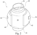
- the left artificial ventricle 12 is shown in greater detail in Figure 2 and is provided with a one-way valve 36 at the outlet 18 thereof.
- the one-way valve 36 is a diaphragm check valve in this example but any suitable one-way valve may be used.
- There is a resilient outer wall 38 which defines the chamber 20 of the left artificial ventricle 12.
- the resilient outer wall 38 and therefore the left artificial ventricle 12 are substantially ovoid in this example as this shape may prevent thrombosis formation.
- the left artificial ventricle 12 may have any suitable geometry.
- the pads 40 and 42 are flexible pads 40 and 42 on opposite sides of the resilient outer wall 38.
- the pads 40 and 42 are symmetrical in shape but one of the pads 40 is provided with a magnetic field generator in the form of an electromagnet 44 while the other one of the pads 42 is provided with a material 46 which will be attracted to the electromagnet 44 when the electromagnet 44 generates a magnetic field.
- the material 46 is a metal in this example.
- the material may be a magnetic field generator that generates a magnetic field having a polarity opposite to the magnetic field generated by the electromagnet 44.
- the electromagnet 44 and the material 46 may be disposed on or within their respective flexible pads 40 and 42.
- a magnetic field generator and a material which will be attracted to the magnetic field generator when the magnetic field generator generates a magnetic field may both be integral with the walls of the outer wall of the chamber.
- FIG. 3 the left artificial ventricle 12 is shown in an expanded configuration.
- Figure 4 the left artificial ventricle 12 is shown in a contracted configuration.
- An electrical energy supply 48 for example a battery, is electrically connected with the electromagnet 44 via an electrical conductor which, in this example, is a wire 50.
- the electrical energy supply 48 is driven by a controller 52 which receives signals from an ECG signal source 54.
- the controller 52 drives the electrical energy supply 48 to energize the electromagnet 44 when the ECG signal source 54 signals that there is ventricular diastole and the controller 52 drives the electrical energy supply 48 to de-energize the electromagnet 44 when the ECG signal source 54 signals that there is ventricular systole.
- the electrical energy supply 48, the controller 52, and the ECG signal source 54 may all be part of an implanted pacemaker type device 56.
- the left artificial ventricle 12 moves from the expanded configuration to the contracted configuration when the electromagnet 44 is energized. This is because the electromagnet 44 and the material 46 in the respective flexible pads 40 and 42 are then drawn towards one another.
- the pressure differential when the left artificial ventricle 12 is in the contracted configuration opens the one-way valve 36 and blood in the chamber 20 flows into the aorta 24 through the outlet 18 as indicated generally by arrow 110 in Figure 4 .
- the left artificial ventricle 12 moves from the contracted configuration to the expanded configuration when the electromagnet 44 is de-energized. This is because the electromagnet 44 and the material 46 in the respective flexible pads 40 and 42 are no longer attracted to one another and the resilient nature of the resilient outer wall 38 actuates the left artificial ventricle 12 to move to the expanded configuration.
- the pressure differential when the left artificial ventricle 12 is in the expanded configuration closes the one-way valve 36. Accordingly, blood which flows into the chamber 20 through the inlet 16, as indicated generally by arrow 120 in Figure 3 , is stored in the chamber and the chamber temporarily functions as a blood reservoir.
- a portion of the ascending aorta is surgically removed and the left artificial ventricle 12 is implanted to replace the removed portion of the aorta.
- the two pads 40 and 42 are disposed on the resilient outer wall 38 of the chamber 20 on opposite sides of the resilient outer wall 38.
- One of the pads 40 is provided with the electromagnet 44 while the other one of the pads 42 is provided with the material 46 which is attracted to the electromagnet 44 when the electromagnet 44 generates a magnetic field.
- the electromagnet 44 is connected to the implanted pacemaker type device 56 through the wire 50.
- the implanted pacemaker type device 56 senses the patient's ECG and energizes and de-energizes the electromagnet 44 based on the patient's ECG.
- the electromagnet 44 is de-energized and the artificial ventricle 12 moves from the contracted configuration to the expanded configuration when the failed left ventricle 22 contracts as indicated by an R wave of the ECG.
- the one-way valve 36 at the outlet 18 simultaneously closes and the pressure inside the chamber 20 decreases while the aortic valve opens. The result is blood flow from the failed left ventricle 22 through the inlet 16 and into the chamber 20 of the left artificial ventricle 12.
- the electromagnet 44 is then energized and the artificial ventricle 12 moves from the expanded configuration to the contracted configuration when the failed left ventricle 22 relaxes as indicated by a T wave of the ECG.
- the one-way valve 36 at the outlet 18 simultaneously opens so the blood stored in the chamber 20 flows into the aorta 24.
- the left ventricle may accordingly function merely as a pathway for blood flowing from the left atrium to the left artificial ventricle 12 while the left artificial ventricle 12 functions as a pump.
- the right artificial ventricle 14 functions in a substantially similar manner with the exception that a portion of the pulmonary trunk is surgically removed and the right artificial ventricle 14 is implanted to replace the removed portion of the pulmonary trunk.
- the right ventricle may then merely function as a pathway for blood flowing from the right atrium to the right artificial ventricle 14 while the right artificial ventricle 14 functions as a pump.
- the mechanism for actuating the artificial ventricle between the expanded configuration and the contracted configuration is an electromagnetic mechanism.
- other mechanisms such as mechanical mechanisms, hydraulic mechanisms, electrical mechanisms, etc. may be used to actuate the artificial ventricle between the expanded configuration and the contracted configuration.
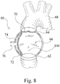
- Figures 8 and 9 show another artificial ventricle 60 implanted in a failed left ventricle (not shown).
- the artificial ventricle 60 generally comprises an inlet 62, an outlet 64, and a main chamber 66 disposed between the inlet 62 and the outlet 64.
- the inlet 62 of the artificial ventricle 60 is in fluid communication with the failed left ventricle and the outlet 64 of the artificial ventricle 60 is in fluid communication with the aorta 68.
- a resilient member 72 separates the main chamber 66 from an expansion chamber 74 which is in fluid communication with a fluid source via a conduit 76.
- the artificial ventricle 60 may be actuated from an expanded configuration, shown in Figure 8 , and a contracted configuration, shown in Figure 9 , by introducing fluid into the expansion chamber 74.
- the artificial ventricle 60 may be actuated from the contracted configuration to the expanded configuration by withdrawing fluid from the expansion chamber 74.
- the pressure differential when the artificial ventricle 60 is in the contracted configuration opens the one-way valve 70 and blood in the main chamber 66 flows into the aorta 68 through the outlet 64 as indicated generally by arrow 130 in Figure 9 .
- the pressure differential when the artificial ventricle 60 is in the expanded configuration closes the one-way valve 70. Accordingly, blood which flows into the chamber 20 through the inlet 62, as indicated generally by arrow 140 in Figure 8 , is stored in the chamber and the chamber temporarily functions as a blood reservoir.
- Figures 10 and 11 show yet another artificial ventricle 80 which is generally similar to the artificial ventricle 60 shown in Figures 8 and 9 with the exception that the main chamber 82 is disposed between expansion chambers 84 and 86.
- the artificial ventricles disclosed herein may be fully implanted and replace the function of a late stage or fully failed ventricle. Blood volume per stroke may be designed into the shape and contraction means to achieve normal ventricle performance levels. Blood volume per stroke may be independent of ventricle performance. Providing the artificial ventricle with a one-way or back-flow prevention valve may improve efficiency by preventing blood flow back into the chamber.
Description
- The present invention relates to ventricular assist devices and, in particular, to implantable artificial ventricles (eg. see
US3768931 ). - It is known to use intra-aortic balloon pumps, operating in counterpulsation, to assist heart function. However, intra-aortic balloon pumps may be insufficient to sustain hemodynamics if the left heart is severely injured. There have accordingly been a number of alternative devices developed for assisting heart function in patients with chronic heart failure. For example, United States Patent Number
7,347,811 which issued on March 25, 2008 to Peters et al. . discloses a device for providing counter-pulsation heart assist by deforming the aorta. In a preferred embodiment, the deformation pressure is applied cyclically, preferably in synchrony with the diastolic period of the heart. The deformation pressure may be applied to the outer wall of the aorta or to a patch covering a resected opening in the wall of the aorta. There however remains a need for improved ventricular assist devices. - It is an object of the present invention to provide an artificial ventricle and a method of artificial ventricle assist.
- There is provided an artificial ventricle comprising an inlet for receiving blood, an outlet for discharging blood, and a chamber disposed between the inlet and the outlet. There is also a mechanism for actuating the artificial ventricle between an expanded configuration and a contracted configuration. In the expanded configuration blood flows into the inlet. In the contracted configuration blood flows out of the outlet. There may be a one-way valve at the outlet for preventing blood flow back into the chamber. The one-way valve may be a diaphragm valve. The chamber may have a resilient outer wall. The chamber may have an ovoid shape.
- The mechanism for actuating the artificial ventricle between the expanded configuration and the contracted configuration may include a first pad disposed on the resilient outer wall of the chamber and a second pad disposed on the resilient outer wall of the chamber opposite of the first pad. The first pad may have a magnetic field generator and the second pad may have a material which is attracted to the magnetic field generator when the magnetic field generator generates a magnetic field. The second pad may move towards the first pad when the magnetic field generator generates a magnetic field, and thereby actuate the artificial ventricle to the contracted configuration by contracting the resilient outer wall of the chamber. The resilient outer wall of the chamber may actuate the artificial ventricle to the expanded configuration when the magnetic field generator is not generating a magnetic field and the material is not attracted to the magnetic field generator.
- The mechanism for actuating the artificial ventricle between the expanded configuration and the contracted configuration may alternatively include a magnetic field generator integral with the resilient outer wall of the chamber and a material integral with the resilient outer wall of the chamber which is attracted to the magnetic field generator when the magnetic field generator generates a magnetic field. The material may move toward the magnetic field generator when the magnetic field generator generates a magnetic field and thereby actuate the artificial ventricle to the contracted configuration by contracting the resilient outer wall of the chamber. The resilient outer wall of the chamber may actuate the artificial ventricle to the expanded configuration when the magnetic field generator is not generating a magnetic field and the material is not attracted to the magnetic field generator.
- The artificial ventricle may further include an electrical energy supply electrically connected to the magnetic field generator, a controller which drives the electric energy supply to either energize or de-energize the magnetic field generator, and an ECG signal generator which signals the controller when there is ventricular diastole and ventricular systole. The controller may drive the electrical energy supply to energize the magnetic field generator when the ECG signal generator signals the controller that there is ventricular diastole. The controller may drive the electrical energy supply to de-energize the magnetic field generator when the ECG signal generator signals the controller that there is ventricular systole.
- There is also provided a method of left ventricle assist comprising removing a portion of the aorta distal of the native aortic valve and implanting an artificial ventricle to replace the removed portion of the aorta. The artificial ventricle comprises an inlet for receiving blood, an outlet for discharging blood, and a chamber disposed between the inlet and the outlet. There is also a mechanism for actuating the artificial ventricle between an expanded configuration and a contracted configuration. In the expanded configuration blood flows into the inlet. In the contracted configuration blood flows out of the outlet. The artificial ventricle is actuated to the expanded configuration during ventricular systole and the artificial ventricle is actuated to the contracted configuration during ventricular diastole.
- There is further provided a method of right ventricle assist comprising removing a portion of the pulmonary artery distal of the native pulmonic valve and implanting an artificial ventricle to replace the removed portion of the pulmonary artery. The artificial ventricle comprises an inlet for receiving blood, an outlet for discharging blood, and a chamber disposed between the inlet and the outlet. There is also a mechanism for actuating the artificial ventricle between an expanded configuration and a contracted configuration. In the expanded configuration blood flows into the inlet. In the contracted configuration blood flows out of the outlet. The artificial ventricle is actuated to the expanded configuration during ventricular systole and the artificial ventricle is actuated to the contracted configuration during ventricular diastole.
- The invention will be more readily understood from the following description of the embodiments thereof given, by way of example only, with reference to the accompanying drawings, in which:
-
Figure 1 is a fragmentary, sectional view of a biventricular failed heart provided with an implanted left artificial ventricle and an implanted right artificial ventricle; -
Figure 2 is a perspective view of the left artificial ventricle ofFigure 1 ; -
Figure 3 is a sectional view of the left artificial ventricle ofFigure 1 in an expanded configuration; -
Figure 4 is a sectional view of the left artificial ventricle ofFigure 1 in a contracted configuration; -
Figure 5 is a flowchart showing a method for providing left ventricle assist; -
Figure 6 is a flowchart showing a method for providing right ventricle assist; -
Figure 7 is a flowchart showing operation of the artificial ventricles ofFigure 1 ; -
Figure 8 is a sectional view of another artificial ventricle in an expanded configuration; -
Figure 9 is a sectional view of the artificial ventricle ofFigure 8 in a contracted configuration; -
Figure 10 is a sectional view of another artificial ventricle in an expanded configuration; and -
Figure 11 is a sectional view of the artificial ventricle ofFigure 10 in a contracted configuration. - Referring to the drawings and first to
Figure 1 , there is shown a biventricular failedheart 10 provided with an implanted leftartificial ventricle 12 and an implanted rightartificial ventricle 14. The leftartificial ventricle 12 generally comprises aninlet 16, anoutlet 18, and achamber 20 disposed between theinlet 16 and theoutlet 18. Theinlet 16 of the leftartificial ventricle 12 is in fluid communication with a failedleft ventricle 22 of theheart 10 and theoutlet 18 of the left artificial ventricle is surgically connected to and in fluid communication with theaorta 24. The leftartificial ventricle 12 accordingly assists blood flow from theleft ventricle 22 to theaorta 24. More specifically, a portion of theaorta 24 distal of the native aortic valve (not shown) is removed and replaced by the leftartificial ventricle 12. Theinlet 16 of the leftartificial ventricle 12 is connected to a proximal open end of theaorta 24. Theoutlet 18 of the leftartificial ventricle 12 is connected to a distal open end of theaorta 24. The failedleft ventricle 22 functions as a pathway for blood flow from the left atrium to theaorta 24 as well as a blood reservoir as will be described below. - Likewise the right
artificial ventricle 14 generally comprises aninlet 26, an outlet 28, and achamber 30 disposed between theinlet 26 and the outlet 28. Theinlet 26 of the rightartificial ventricle 14 is in fluid communication with a failedright ventricle 32 of theheart 10 and the outlet 28 of the left artificial ventricle is surgically connected to and in fluid communication with the pulmonary artery 34. The rightartificial ventricle 14 accordingly allows for blood flow from theright ventricle 32 to the pulmonary artery 34. More specifically, a portion of the pulmonary artery 34 distal of the native pulmonic valve (not shown) is removed and replaced by the rightartificial ventricle 14. Theinlet 26 of the rightartificial ventricle 14 is surgically connected to a proximal open end of the pulmonary artery 34. The outlet 28 of the rightartificial ventricle 14 is connected to a distal open end of the pulmonary artery 34. The failedright ventricle 32 functions as a pathway for blood flow from the right atrium to the pulmonary artery 34 as well as a blood reservoir as will be described below. - The left
artificial ventricle 12 and the rightartificial ventricle 14 have a substantially identical structure and function in a substantially identical manner. Accordingly, only the leftartificial ventricle 12 is described in detail herein with the understanding that the rightartificial ventricle 14 has a substantially identical structure and functions in a substantially identical manner. The leftartificial ventricle 12 is shown in greater detail inFigure 2 and is provided with a one-way valve 36 at theoutlet 18 thereof. The one-way valve 36 is a diaphragm check valve in this example but any suitable one-way valve may be used. There is a resilientouter wall 38 which defines thechamber 20 of the leftartificial ventricle 12. The resilientouter wall 38 and therefore the leftartificial ventricle 12 are substantially ovoid in this example as this shape may prevent thrombosis formation. However, in other examples, the leftartificial ventricle 12 may have any suitable geometry. - There are
flexible pads outer wall 38. In this example, thepads pads 40 is provided with a magnetic field generator in the form of anelectromagnet 44 while the other one of thepads 42 is provided with a material 46 which will be attracted to theelectromagnet 44 when theelectromagnet 44 generates a magnetic field. Thematerial 46 is a metal in this example. However, in other examples the material may be a magnetic field generator that generates a magnetic field having a polarity opposite to the magnetic field generated by theelectromagnet 44. Theelectromagnet 44 and thematerial 46 may be disposed on or within their respectiveflexible pads - Referring now to
Figures 3 and4 , operation of the leftartificial ventricle 12 is shown. InFigure 3 the leftartificial ventricle 12 is shown in an expanded configuration. InFigure 4 the leftartificial ventricle 12 is shown in a contracted configuration. Anelectrical energy supply 48, for example a battery, is electrically connected with theelectromagnet 44 via an electrical conductor which, in this example, is awire 50. Theelectrical energy supply 48 is driven by acontroller 52 which receives signals from anECG signal source 54. Thecontroller 52 drives theelectrical energy supply 48 to energize theelectromagnet 44 when theECG signal source 54 signals that there is ventricular diastole and thecontroller 52 drives theelectrical energy supply 48 to de-energize theelectromagnet 44 when theECG signal source 54 signals that there is ventricular systole. Theelectrical energy supply 48, thecontroller 52, and theECG signal source 54 may all be part of an implantedpacemaker type device 56. - The left
artificial ventricle 12 moves from the expanded configuration to the contracted configuration when theelectromagnet 44 is energized. This is because theelectromagnet 44 and the material 46 in the respectiveflexible pads artificial ventricle 12 is in the contracted configuration opens the one-way valve 36 and blood in thechamber 20 flows into theaorta 24 through theoutlet 18 as indicated generally byarrow 110 inFigure 4 . The leftartificial ventricle 12 moves from the contracted configuration to the expanded configuration when theelectromagnet 44 is de-energized. This is because theelectromagnet 44 and the material 46 in the respectiveflexible pads outer wall 38 actuates the leftartificial ventricle 12 to move to the expanded configuration. The pressure differential when the leftartificial ventricle 12 is in the expanded configuration closes the one-way valve 36. Accordingly, blood which flows into thechamber 20 through theinlet 16, as indicated generally byarrow 120 inFigure 3 , is stored in the chamber and the chamber temporarily functions as a blood reservoir. - In operation, a portion of the ascending aorta is surgically removed and the left
artificial ventricle 12 is implanted to replace the removed portion of the aorta. The twopads outer wall 38 of thechamber 20 on opposite sides of the resilientouter wall 38. One of thepads 40 is provided with theelectromagnet 44 while the other one of thepads 42 is provided with the material 46 which is attracted to theelectromagnet 44 when theelectromagnet 44 generates a magnetic field. Theelectromagnet 44 is connected to the implantedpacemaker type device 56 through thewire 50. The implantedpacemaker type device 56 senses the patient's ECG and energizes and de-energizes theelectromagnet 44 based on the patient's ECG. Theelectromagnet 44 is de-energized and theartificial ventricle 12 moves from the contracted configuration to the expanded configuration when the failedleft ventricle 22 contracts as indicated by an R wave of the ECG. The one-way valve 36 at theoutlet 18 simultaneously closes and the pressure inside thechamber 20 decreases while the aortic valve opens. The result is blood flow from the failedleft ventricle 22 through theinlet 16 and into thechamber 20 of the leftartificial ventricle 12. Theelectromagnet 44 is then energized and theartificial ventricle 12 moves from the expanded configuration to the contracted configuration when the failedleft ventricle 22 relaxes as indicated by a T wave of the ECG. The one-way valve 36 at theoutlet 18 simultaneously opens so the blood stored in thechamber 20 flows into theaorta 24. The left ventricle may accordingly function merely as a pathway for blood flowing from the left atrium to the leftartificial ventricle 12 while the leftartificial ventricle 12 functions as a pump. - The right
artificial ventricle 14 functions in a substantially similar manner with the exception that a portion of the pulmonary trunk is surgically removed and the rightartificial ventricle 14 is implanted to replace the removed portion of the pulmonary trunk. The right ventricle may then merely function as a pathway for blood flowing from the right atrium to the rightartificial ventricle 14 while the rightartificial ventricle 14 functions as a pump. - In the example shown in
Figures 1 to 7 , the mechanism for actuating the artificial ventricle between the expanded configuration and the contracted configuration is an electromagnetic mechanism. However, in other examples other mechanisms such as mechanical mechanisms, hydraulic mechanisms, electrical mechanisms, etc. may be used to actuate the artificial ventricle between the expanded configuration and the contracted configuration. For example,Figures 8 and9 show anotherartificial ventricle 60 implanted in a failed left ventricle (not shown). Theartificial ventricle 60 generally comprises aninlet 62, anoutlet 64, and amain chamber 66 disposed between theinlet 62 and theoutlet 64. Theinlet 62 of theartificial ventricle 60 is in fluid communication with the failed left ventricle and theoutlet 64 of theartificial ventricle 60 is in fluid communication with theaorta 68. There is a one-way valve 70 at theoutlet 64 of theartificial ventricle 60. Aresilient member 72 separates themain chamber 66 from anexpansion chamber 74 which is in fluid communication with a fluid source via aconduit 76. - The
artificial ventricle 60 may be actuated from an expanded configuration, shown inFigure 8 , and a contracted configuration, shown inFigure 9 , by introducing fluid into theexpansion chamber 74. Theartificial ventricle 60 may be actuated from the contracted configuration to the expanded configuration by withdrawing fluid from theexpansion chamber 74. The pressure differential when theartificial ventricle 60 is in the contracted configuration opens the one-way valve 70 and blood in themain chamber 66 flows into theaorta 68 through theoutlet 64 as indicated generally byarrow 130 inFigure 9 . The pressure differential when theartificial ventricle 60 is in the expanded configuration closes the one-way valve 70. Accordingly, blood which flows into thechamber 20 through theinlet 62, as indicated generally byarrow 140 inFigure 8 , is stored in the chamber and the chamber temporarily functions as a blood reservoir. -
Figures 10 and11 show yet anotherartificial ventricle 80 which is generally similar to theartificial ventricle 60 shown inFigures 8 and9 with the exception that themain chamber 82 is disposed betweenexpansion chambers - The artificial ventricles disclosed herein may be fully implanted and replace the function of a late stage or fully failed ventricle. Blood volume per stroke may be designed into the shape and contraction means to achieve normal ventricle performance levels. Blood volume per stroke may be independent of ventricle performance. Providing the artificial ventricle with a one-way or back-flow prevention valve may improve efficiency by preventing blood flow back into the chamber.
- It will be understood by a person skilled in the art that many of the details provided above are by way of example only, and are not intended to limit the scope of the invention which is to be determined with reference to the following claims.
Claims (7)
- An artificial ventricle (12 or 14) comprising:an inlet (16 or 26) for receiving blood;an outlet (18 or 28) for discharging blood;a chamber (20 or 30) disposed between the inlet (16 or 26) and the outlet (18 or 28);a mechanism for actuating the artificial ventricle (12 or 14) between an expanded configuration and a contracted configuration, wherein in the expanded configuration blood flows into the inlet (16 or 26) and in the contracted configuration blood flows out of the outlet (18 or 28); andcharacterised in that the chamber (20 or 30) has a resilient outer wall (38) and the mechanism for actuating the artificial ventricle (12 or 14) between the expanded configuration and the contracted configuration includes:a first pad (40) disposed on the resilient outer wall (38) of the chamber (20 or 30), the first pad (40) having a magnetic field generator; anda second pad (42) disposed on the resilient outer wall (38) of the chamber (20 or 30) opposite of the first pad (40), the second pad (42) having a material (46) which is attracted to the magnetic field generator when the magnetic field generator generates a magnetic field, wherein the second pad (42) moves towards the first pad (40) when the magnetic field generator generates a magnetic field and thereby actuates the artificial ventricle (12 or 14) to the contracted configuration by contracting the resilient outer wall (38) of the chamber (20 or 30), and wherein the resilient outer wall (38) of the chamber (20 or 30) actuates the artificial ventricle (12 or 14) to the expanded configuration when the magnetic field generator is not generating a magnetic field and the material (46) is not attracted to the magnetic field generator.
- The artificial ventricle (12 or 14) as claimed in claim 1 comprising:the inlet (16 or 26) for receiving blood;the outlet (18 or 28) for discharging blood;the chamber (20 or 30) disposed between the inlet (16 or 26) and the outlet (18 or 28);the mechanism for actuating the artificial ventricle (12 or 14) between an expanded configuration and a contracted configuration, wherein in the expanded configuration blood flows into the inlet (16 or 26) and in the contracted configuration blood flows out of the outlet (18 or 28);a one-way valve (36) at the outlet (18 or 28) for preventing blood flow back into the chamber (20 or 30), andcharacterised in that the chamber (20 or 30) has the resilient outer wall (38) and the mechanism for actuating the artificial ventricle (12 or 14) between the expanded configuration and the contracted configuration includes:the first pad (40) disposed on the resilient outer wall (38) of the chamber (20 or 30), the first pad (40) having the magnetic field generator; andthe second pad (42) disposed on the resilient outer wall (38) of the chamber (20 or 30) opposite of the first pad (40), the second pad (42) having the material (46) which is attracted to the magnetic field generator when the magnetic field generator generates a magnetic field, wherein the second pad (42) moves towards the first pad (40) when the magnetic field generator generates a magnetic field and thereby actuates the artificial ventricle (12 or 14) to the contracted configuration by contracting the resilient outer wall (38) of the chamber (20 or 30), and wherein the resilient outer wall (38) of the chamber (20 or 30) actuates the artificial ventricle (12 or 14) to the expanded configuration when the magnetic field generator is not generating a magnetic field and the material (46) is not attracted to the magnetic field generator.
- The artificial ventricle (12 or 14) as claimed in claim 2 wherein the one-way valve (36) is a diaphragm valve.
- The artificial ventricle (12 or 14) as claimed in claim 1 or 2 wherein the chamber (20 or 30) has an ovoid shape.
- The artificial ventricle (12 or 14) as claimed in claim 1 or 2 further including:an electrical energy supply (48) electrically connected to the magnetic field generator;a controller (52) which drives the electrical energy supply (48) to either energize or de-energize the magnetic field generator; andan ECG signal generator (54) which signals the controller (52) when there is ventricular diastole and ventricular systole, wherein the controller (52) drives the electrical energy supply (48) to energize the magnetic field generator when the ECG signal generator (54) signals the controller (52) that there is ventricular diastole and wherein the controller (52) drives the electrical energy supply (48) to de-energize the magnetic field generator when the ECG signal generator (54) signals the controller (52) that there is ventricular systole.
- An artificial ventricle (12 or 14) comprising an inlet (16 or 26) for receiving blood;
an outlet (18 or 28) for discharging blood;
a chamber (20 or 30) disposed between the inlet (16 or 26) and the outlet (18 or 28);
a mechanism for actuating the artificial ventricle (12 or 14) between an expanded configuration and a contracted configuration, wherein in the expanded configuration blood flows into the inlet (16 or 26) and in the contracted configuration blood flows out of the outlet (18 or 28); and
characterised in that the chamber (20 or 30) has a resilient outer wall (38) and the mechanism for actuating the artificial ventricle (12 or 14) between the expanded configuration and the contracted configuration includes:a magnetic field generator in the resilient outer wall (38) of the chamber (20 and 30); anda material (46) in the resilient outer wall (38) of the chamber (20 or 30) which is attracted to the magnetic field generator when the magnetic field generator generates a magnetic field, wherein the material (46) moves towards the magnetic field generator when the magnetic field generator generates a magnetic field and thereby actuates the artificial ventricle (12 or 14) to the contracted configuration by contracting the resilient outer wall (38) of the chamber (20 or 30), and wherein the resilient outer wall (38) of the chamber (20 or 30) actuates the artificial ventricle (12 or 14) to the expanded configuration when the magnetic field generator is not generating a magnetic field and the material (46) is not attracted to the magnetic field generator. - The artificial ventricle (12 or 14) as claimed in claim 6 further including:an electrical energy supply (48) electrically connected to the magnetic field generator;a controller (52) which drives the electrical energy supply (48) to either energize or de-energize the magnetic field generator; andan ECG signal generator (54) which signals the controller (52) when there is ventricular diastole and ventricular systole, wherein the controller (52) drives the electrical energy supply (48) to energize the magnetic field generator when the ECG signal generator (54) signals the controller (52) that there is ventricular diastole and wherein the controller (52) drives the electrical energy supply (48) to de-energize the magnetic field generator when the ECG signal generator (54) signals the controller (52) that there is ventricular systole.
Applications Claiming Priority (2)
| Application Number | Priority Date | Filing Date | Title |
|---|---|---|---|
| US13/924,472 US9320841B2 (en) | 2013-06-21 | 2013-06-21 | Ventricular assist device |
| PCT/CA2014/050598 WO2014201575A1 (en) | 2013-06-21 | 2014-06-23 | Artificial ventricles |
Publications (4)
| Publication Number | Publication Date |
|---|---|
| EP3010564A1 EP3010564A1 (en) | 2016-04-27 |
| EP3010564A4 EP3010564A4 (en) | 2017-03-01 |
| EP3010564B1 true EP3010564B1 (en) | 2020-10-14 |
| EP3010564B8 EP3010564B8 (en) | 2020-12-30 |
Family
ID=52103759
Family Applications (1)
| Application Number | Title | Priority Date | Filing Date |
|---|---|---|---|
| EP14813602.1A Active EP3010564B8 (en) | 2013-06-21 | 2014-06-23 | Artificial ventricles |
Country Status (6)
| Country | Link |
|---|---|
| US (1) | US9320841B2 (en) |
| EP (1) | EP3010564B8 (en) |
| JP (1) | JP6647196B2 (en) |
| CN (1) | CN105517590B (en) |
| CA (1) | CA2916350C (en) |
| WO (1) | WO2014201575A1 (en) |
Families Citing this family (26)
| Publication number | Priority date | Publication date | Assignee | Title |
|---|---|---|---|---|
| US8579964B2 (en) | 2010-05-05 | 2013-11-12 | Neovasc Inc. | Transcatheter mitral valve prosthesis |
| US9554897B2 (en) | 2011-04-28 | 2017-01-31 | Neovasc Tiara Inc. | Methods and apparatus for engaging a valve prosthesis with tissue |
| US9308087B2 (en) | 2011-04-28 | 2016-04-12 | Neovasc Tiara Inc. | Sequentially deployed transcatheter mitral valve prosthesis |
| US9345573B2 (en) | 2012-05-30 | 2016-05-24 | Neovasc Tiara Inc. | Methods and apparatus for loading a prosthesis onto a delivery system |
| US9572665B2 (en) | 2013-04-04 | 2017-02-21 | Neovasc Tiara Inc. | Methods and apparatus for delivering a prosthetic valve to a beating heart |
| US9320841B2 (en) | 2013-06-21 | 2016-04-26 | Corvivo, Inc. | Ventricular assist device |
| US9814816B2 (en) | 2013-06-21 | 2017-11-14 | Corvivo, Inc. | Artificial ventricles |
| WO2017127939A1 (en) | 2016-01-29 | 2017-08-03 | Neovasc Tiara Inc. | Prosthetic valve for avoiding obstruction of outflow |
| CN106310411A (en) * | 2016-10-25 | 2017-01-11 | 哈尔滨医科大学 | Ascending aorta type ventricular assisting device |
| CN113893064A (en) | 2016-11-21 | 2022-01-07 | 内奥瓦斯克迪亚拉公司 | Methods and systems for rapid retrieval of transcatheter heart valve delivery systems |
| JP2020519323A (en) * | 2017-04-28 | 2020-07-02 | ヌハート エーエスNuheart As | Ventricular assist device and method |
| EP3672530A4 (en) | 2017-08-25 | 2021-04-14 | Neovasc Tiara Inc. | Sequentially deployed transcatheter mitral valve prosthesis |
| US11737872B2 (en) | 2018-11-08 | 2023-08-29 | Neovasc Tiara Inc. | Ventricular deployment of a transcatheter mitral valve prosthesis |
| CN109876217A (en) * | 2019-01-29 | 2019-06-14 | 哈尔滨工业大学(深圳) | Ventricular assist device line outlet waterproof construction |
| JP7438236B2 (en) | 2019-04-01 | 2024-02-26 | ニオバスク ティアラ インコーポレイテッド | Controllably deployable prosthetic valve |
| EP3952792A4 (en) | 2019-04-10 | 2023-01-04 | Neovasc Tiara Inc. | Prosthetic valve with natural blood flow |
| US11779742B2 (en) | 2019-05-20 | 2023-10-10 | Neovasc Tiara Inc. | Introducer with hemostasis mechanism |
| AU2020295566B2 (en) | 2019-06-20 | 2023-07-20 | Neovasc Tiara Inc. | Low profile prosthetic mitral valve |
| CN110755708A (en) * | 2019-10-31 | 2020-02-07 | 武汉大学 | Left ventricle auxiliary device outside heart chamber |
| CN111298225A (en) * | 2019-12-02 | 2020-06-19 | 李勇 | Balloon heart counterpulsation device comprising electromagnet |
| CN111494747A (en) * | 2020-04-27 | 2020-08-07 | 宋春丽 | Paediatrics nursing is with paediatrics negative pressure gastric lavage device |
| CN113368388B (en) * | 2021-06-21 | 2022-12-02 | 内蒙古工业大学 | Left ventricle auxiliary pulsation type blood pump |
| CN114367033A (en) * | 2022-01-06 | 2022-04-19 | 中国科学院力学研究所 | Artificial heart with interchangeable inner cavity volume and control method thereof |
| CN114367031A (en) * | 2022-01-06 | 2022-04-19 | 中国科学院力学研究所 | Progressive contraction type wedge-shaped artificial blood pump, artificial heart and control method of artificial heart |
| FR3139472A1 (en) * | 2022-09-14 | 2024-03-15 | Bypa Medical Solutions | Heart assistance or replacement device |
| CN116099121A (en) * | 2023-03-15 | 2023-05-12 | 江苏大学 | Novel magnetic drive direct ventricular assist device |
Family Cites Families (29)
| Publication number | Priority date | Publication date | Assignee | Title |
|---|---|---|---|---|
| US3768931A (en) | 1971-05-03 | 1973-10-30 | Birch R | Magnetically actuated pump with flexible membrane |
| US4185617A (en) * | 1978-04-27 | 1980-01-29 | Hutchins Thomas B | Magnetically driven cardiac-assist pump system |
| US4621617A (en) | 1981-06-29 | 1986-11-11 | Sharma Devendra N | Electro-magnetically controlled artificial heart device for compressing cardiac muscle |
| US5332403A (en) | 1992-08-17 | 1994-07-26 | Jack Kolff | LVAD with t-shape and unidirectional valve |
| US5498228A (en) | 1994-08-08 | 1996-03-12 | John W. Royalty | Electromagnetic bi-ventricular assist device |
| US6610004B2 (en) * | 1997-10-09 | 2003-08-26 | Orqis Medical Corporation | Implantable heart assist system and method of applying same |
| US6251061B1 (en) * | 1998-09-09 | 2001-06-26 | Scimed Life Systems, Inc. | Cardiac assist device using field controlled fluid |
| US6264601B1 (en) * | 1999-04-02 | 2001-07-24 | World Heart Corporation | Implantable ventricular assist device |
| US6123724A (en) | 1999-04-14 | 2000-09-26 | Denker; Stephen | Heart assist method and apparatus employing magnetic repulsion force |
| AUPQ090499A0 (en) * | 1999-06-10 | 1999-07-01 | Peters, William S | Heart assist device and system |
| CN1115172C (en) * | 1999-12-27 | 2003-07-23 | 李树文 | Integrated pneumoelectric blood pump and integrated pneumoelectric artificial heart |
| AU2002952691A0 (en) | 2002-11-15 | 2002-11-28 | Sunshine Heart Company Pty Ltd | Heart assist device utilising aortic deformation |
| US6969345B2 (en) * | 2002-12-06 | 2005-11-29 | World Heart Corporation | Miniature, pulsatile implantable ventricular assist devices and methods of controlling ventricular assist devices |
| EP1486217B1 (en) | 2003-06-12 | 2010-05-12 | Terumo Kabushiki Kaisha | Artificial heart pump system and its control apparatus |
| US7273446B2 (en) * | 2003-10-31 | 2007-09-25 | Spence Paul A | Methods, devices and systems for counterpulsation of blood flow to and from the circulatory system |
| US7402134B2 (en) | 2004-07-15 | 2008-07-22 | Micardia Corporation | Magnetic devices and methods for reshaping heart anatomy |
| CN1785136A (en) * | 2004-12-09 | 2006-06-14 | 解启莲 | Bionic heart permanent implanted in heart chamber |
| ITRM20040622A1 (en) | 2004-12-20 | 2005-03-20 | Marzia Murri | ARTIFICIAL HEART (BIO-FEEDABLE) IN APPLICATION OF SPHERICAL PUMP MURRI. |
| US20070083077A1 (en) | 2005-10-06 | 2007-04-12 | Alpha Dev, Llc. | Total artificial heart system for auto-regulating flow and pressure balance |
| WO2007087014A2 (en) | 2006-01-12 | 2007-08-02 | Arrow International, Inc. | Adaptive real time ecg triggering and uses thereof |
| WO2008010905A2 (en) * | 2006-06-30 | 2008-01-24 | Cvdevices, Llc | Percutaneous intravascular access to cardiac tissue |
| JP5174891B2 (en) * | 2007-04-27 | 2013-04-03 | シーヴィ デヴァイシズ,エルエルシー | Devices, systems, and methods for accessing the epicardial surface of the heart |
| US8105265B2 (en) * | 2007-10-12 | 2012-01-31 | Deka Products Limited Partnership | Systems, devices and methods for cardiopulmonary treatment and procedures |
| JP2011515174A (en) * | 2008-03-26 | 2011-05-19 | カーディオ アシスト リミテッド | Cardiac assist device |
| US8137260B2 (en) | 2008-05-22 | 2012-03-20 | Edwards Lifesciences Corporation | Electromagnetic cardiac assist device and method |
| US9579434B2 (en) * | 2010-03-03 | 2017-02-28 | The Secretary Of Atomic Energy, Govt. Of India | Flexible magnetic membrane based actuation system and devices involving the same |
| KR101066569B1 (en) * | 2010-04-06 | 2011-09-21 | 주식회사 리브라하트 | Polymer valve and pulsatile conduit-type vad using the same |
| CN101869728A (en) * | 2010-06-01 | 2010-10-27 | 曹罡 | Pulsating portal blood pump and manufacturing method thereof |
| US9320841B2 (en) | 2013-06-21 | 2016-04-26 | Corvivo, Inc. | Ventricular assist device |
-
2013
- 2013-06-21 US US13/924,472 patent/US9320841B2/en active Active
-
2014
- 2014-06-23 CA CA2916350A patent/CA2916350C/en active Active
- 2014-06-23 CN CN201480045984.3A patent/CN105517590B/en active Active
- 2014-06-23 JP JP2016520209A patent/JP6647196B2/en active Active
- 2014-06-23 EP EP14813602.1A patent/EP3010564B8/en active Active
- 2014-06-23 WO PCT/CA2014/050598 patent/WO2014201575A1/en active Application Filing
Non-Patent Citations (1)
| Title |
|---|
| None * |
Also Published As
| Publication number | Publication date |
|---|---|
| EP3010564B8 (en) | 2020-12-30 |
| CN105517590A (en) | 2016-04-20 |
| JP2016524509A (en) | 2016-08-18 |
| EP3010564A4 (en) | 2017-03-01 |
| CA2916350A1 (en) | 2014-12-24 |
| US9320841B2 (en) | 2016-04-26 |
| US20140378744A1 (en) | 2014-12-25 |
| CA2916350C (en) | 2023-01-03 |
| EP3010564A1 (en) | 2016-04-27 |
| JP6647196B2 (en) | 2020-02-14 |
| WO2014201575A1 (en) | 2014-12-24 |
| CN105517590B (en) | 2019-01-11 |
Similar Documents
| Publication | Publication Date | Title |
|---|---|---|
| EP3010564B1 (en) | Artificial ventricles | |
| EP2282789B1 (en) | Heart assist device | |
| US6406422B1 (en) | Ventricular-assist method and apparatus | |
| US6969345B2 (en) | Miniature, pulsatile implantable ventricular assist devices and methods of controlling ventricular assist devices | |
| US6949065B2 (en) | Left ventricular assist system | |
| US8286656B2 (en) | Implantable counterpulsation cardiac assist device | |
| US4369530A (en) | Hydraulically actuated cardiac prosthesis and method of actuation | |
| US4381567A (en) | Hydraulically actuated total cardiac prosthesis with reversible pump and three-way ventricular valving | |
| US4397049A (en) | Hydraulically actuated cardiac prosthesis with three-way ventricular valving | |
| US20180064864A1 (en) | Artificial Ventricles | |
| JPH025966A (en) | Embedding artificial heart | |
| US4376312A (en) | Hydraulically actuated cardiac prosthesis | |
| CN102107030A (en) | Cardiac impulse assist device, cardiac impulse assist system and method for treating cardiac failure | |
| US8372145B2 (en) | Implantable artificial ventricle having low energy requirement | |
| US4389737A (en) | Hydraulically actuated cardiac prosthesis with three-way ventricular valving | |
| EP0079373B1 (en) | Hydraulically actuated cardiac prosthesis | |
| US11338123B2 (en) | Blood pump devices and associated systems and methods | |
| Daliri et al. | Cardiac Compression Devices: Alternative Technology and Innovative Concept | |
| KR101105818B1 (en) | Emergency measure device using blood pump and method for using thereof | |
| CN117298445A (en) | Double-ventricle full artificial heart device |
Legal Events
| Date | Code | Title | Description |
|---|---|---|---|
| PUAI | Public reference made under article 153(3) epc to a published international application that has entered the european phase |
Free format text: ORIGINAL CODE: 0009012 |
|
| 17P | Request for examination filed |
Effective date: 20160121 |
|
| AK | Designated contracting states |
Kind code of ref document: A1 Designated state(s): AL AT BE BG CH CY CZ DE DK EE ES FI FR GB GR HR HU IE IS IT LI LT LU LV MC MK MT NL NO PL PT RO RS SE SI SK SM TR |
|
| AX | Request for extension of the european patent |
Extension state: BA ME |
|
| DAX | Request for extension of the european patent (deleted) | ||
| A4 | Supplementary search report drawn up and despatched |
Effective date: 20170130 |
|
| RIC1 | Information provided on ipc code assigned before grant |
Ipc: A61F 2/24 20060101ALI20170124BHEP Ipc: A61M 1/12 20060101AFI20170124BHEP |
|
| STAA | Information on the status of an ep patent application or granted ep patent |
Free format text: STATUS: REQUEST FOR EXAMINATION WAS MADE |
|
| GRAP | Despatch of communication of intention to grant a patent |
Free format text: ORIGINAL CODE: EPIDOSNIGR1 |
|
| STAA | Information on the status of an ep patent application or granted ep patent |
Free format text: STATUS: GRANT OF PATENT IS INTENDED |
|
| INTG | Intention to grant announced |
Effective date: 20200414 |
|
| GRAS | Grant fee paid |
Free format text: ORIGINAL CODE: EPIDOSNIGR3 |
|
| GRAA | (expected) grant |
Free format text: ORIGINAL CODE: 0009210 |
|
| STAA | Information on the status of an ep patent application or granted ep patent |
Free format text: STATUS: THE PATENT HAS BEEN GRANTED |
|
| AK | Designated contracting states |
Kind code of ref document: B1 Designated state(s): AL AT BE BG CH CY CZ DE DK EE ES FI FR GB GR HR HU IE IS IT LI LT LU LV MC MK MT NL NO PL PT RO RS SE SI SK SM TR |
|
| RAP1 | Party data changed (applicant data changed or rights of an application transferred) |
Owner name: DALIAN CORVINO MEDICAL TECHNOLOGICAL CO. LTD |
|
| REG | Reference to a national code |
Ref country code: GB Ref legal event code: FG4D |
|
| REG | Reference to a national code |
Ref country code: AT Ref legal event code: REF Ref document number: 1322964 Country of ref document: AT Kind code of ref document: T Effective date: 20201015 Ref country code: CH Ref legal event code: EP |
|
| GRAT | Correction requested after decision to grant or after decision to maintain patent in amended form |
Free format text: ORIGINAL CODE: EPIDOSNCDEC |
|
| REG | Reference to a national code |
Ref country code: DE Ref legal event code: R096 Ref document number: 602014071277 Country of ref document: DE |
|
| REG | Reference to a national code |
Ref country code: IE Ref legal event code: FG4D |
|
| REG | Reference to a national code |
Ref country code: DE Ref legal event code: R079 Ref document number: 602014071277 Country of ref document: DE Free format text: PREVIOUS MAIN CLASS: A61M0001120000 Ipc: A61M0060122000 |
|
| REG | Reference to a national code |
Ref country code: CH Ref legal event code: PK Free format text: BERICHTIGUNG B8 |
|
| REG | Reference to a national code |
Ref country code: AT Ref legal event code: MK05 Ref document number: 1322964 Country of ref document: AT Kind code of ref document: T Effective date: 20201014 |
|
| REG | Reference to a national code |
Ref country code: NL Ref legal event code: MP Effective date: 20201014 |
|
| PG25 | Lapsed in a contracting state [announced via postgrant information from national office to epo] |
Ref country code: RS Free format text: LAPSE BECAUSE OF FAILURE TO SUBMIT A TRANSLATION OF THE DESCRIPTION OR TO PAY THE FEE WITHIN THE PRESCRIBED TIME-LIMIT Effective date: 20201014 Ref country code: FI Free format text: LAPSE BECAUSE OF FAILURE TO SUBMIT A TRANSLATION OF THE DESCRIPTION OR TO PAY THE FEE WITHIN THE PRESCRIBED TIME-LIMIT Effective date: 20201014 Ref country code: PT Free format text: LAPSE BECAUSE OF FAILURE TO SUBMIT A TRANSLATION OF THE DESCRIPTION OR TO PAY THE FEE WITHIN THE PRESCRIBED TIME-LIMIT Effective date: 20210215 Ref country code: NL Free format text: LAPSE BECAUSE OF FAILURE TO SUBMIT A TRANSLATION OF THE DESCRIPTION OR TO PAY THE FEE WITHIN THE PRESCRIBED TIME-LIMIT Effective date: 20201014 Ref country code: NO Free format text: LAPSE BECAUSE OF FAILURE TO SUBMIT A TRANSLATION OF THE DESCRIPTION OR TO PAY THE FEE WITHIN THE PRESCRIBED TIME-LIMIT Effective date: 20210114 Ref country code: GR Free format text: LAPSE BECAUSE OF FAILURE TO SUBMIT A TRANSLATION OF THE DESCRIPTION OR TO PAY THE FEE WITHIN THE PRESCRIBED TIME-LIMIT Effective date: 20210115 |
|
| REG | Reference to a national code |
Ref country code: LT Ref legal event code: MG4D |
|
| PG25 | Lapsed in a contracting state [announced via postgrant information from national office to epo] |
Ref country code: PL Free format text: LAPSE BECAUSE OF FAILURE TO SUBMIT A TRANSLATION OF THE DESCRIPTION OR TO PAY THE FEE WITHIN THE PRESCRIBED TIME-LIMIT Effective date: 20201014 Ref country code: SE Free format text: LAPSE BECAUSE OF FAILURE TO SUBMIT A TRANSLATION OF THE DESCRIPTION OR TO PAY THE FEE WITHIN THE PRESCRIBED TIME-LIMIT Effective date: 20201014 Ref country code: IS Free format text: LAPSE BECAUSE OF FAILURE TO SUBMIT A TRANSLATION OF THE DESCRIPTION OR TO PAY THE FEE WITHIN THE PRESCRIBED TIME-LIMIT Effective date: 20210214 Ref country code: LV Free format text: LAPSE BECAUSE OF FAILURE TO SUBMIT A TRANSLATION OF THE DESCRIPTION OR TO PAY THE FEE WITHIN THE PRESCRIBED TIME-LIMIT Effective date: 20201014 Ref country code: BG Free format text: LAPSE BECAUSE OF FAILURE TO SUBMIT A TRANSLATION OF THE DESCRIPTION OR TO PAY THE FEE WITHIN THE PRESCRIBED TIME-LIMIT Effective date: 20210114 Ref country code: ES Free format text: LAPSE BECAUSE OF FAILURE TO SUBMIT A TRANSLATION OF THE DESCRIPTION OR TO PAY THE FEE WITHIN THE PRESCRIBED TIME-LIMIT Effective date: 20201014 Ref country code: AT Free format text: LAPSE BECAUSE OF FAILURE TO SUBMIT A TRANSLATION OF THE DESCRIPTION OR TO PAY THE FEE WITHIN THE PRESCRIBED TIME-LIMIT Effective date: 20201014 |
|
| PG25 | Lapsed in a contracting state [announced via postgrant information from national office to epo] |
Ref country code: HR Free format text: LAPSE BECAUSE OF FAILURE TO SUBMIT A TRANSLATION OF THE DESCRIPTION OR TO PAY THE FEE WITHIN THE PRESCRIBED TIME-LIMIT Effective date: 20201014 |
|
| REG | Reference to a national code |
Ref country code: DE Ref legal event code: R097 Ref document number: 602014071277 Country of ref document: DE |
|
| PG25 | Lapsed in a contracting state [announced via postgrant information from national office to epo] |
Ref country code: LT Free format text: LAPSE BECAUSE OF FAILURE TO SUBMIT A TRANSLATION OF THE DESCRIPTION OR TO PAY THE FEE WITHIN THE PRESCRIBED TIME-LIMIT Effective date: 20201014 Ref country code: RO Free format text: LAPSE BECAUSE OF FAILURE TO SUBMIT A TRANSLATION OF THE DESCRIPTION OR TO PAY THE FEE WITHIN THE PRESCRIBED TIME-LIMIT Effective date: 20201014 Ref country code: SK Free format text: LAPSE BECAUSE OF FAILURE TO SUBMIT A TRANSLATION OF THE DESCRIPTION OR TO PAY THE FEE WITHIN THE PRESCRIBED TIME-LIMIT Effective date: 20201014 Ref country code: EE Free format text: LAPSE BECAUSE OF FAILURE TO SUBMIT A TRANSLATION OF THE DESCRIPTION OR TO PAY THE FEE WITHIN THE PRESCRIBED TIME-LIMIT Effective date: 20201014 Ref country code: CZ Free format text: LAPSE BECAUSE OF FAILURE TO SUBMIT A TRANSLATION OF THE DESCRIPTION OR TO PAY THE FEE WITHIN THE PRESCRIBED TIME-LIMIT Effective date: 20201014 Ref country code: SM Free format text: LAPSE BECAUSE OF FAILURE TO SUBMIT A TRANSLATION OF THE DESCRIPTION OR TO PAY THE FEE WITHIN THE PRESCRIBED TIME-LIMIT Effective date: 20201014 |
|
| PLBE | No opposition filed within time limit |
Free format text: ORIGINAL CODE: 0009261 |
|
| STAA | Information on the status of an ep patent application or granted ep patent |
Free format text: STATUS: NO OPPOSITION FILED WITHIN TIME LIMIT |
|
| PG25 | Lapsed in a contracting state [announced via postgrant information from national office to epo] |
Ref country code: DK Free format text: LAPSE BECAUSE OF FAILURE TO SUBMIT A TRANSLATION OF THE DESCRIPTION OR TO PAY THE FEE WITHIN THE PRESCRIBED TIME-LIMIT Effective date: 20201014 |
|
| 26N | No opposition filed |
Effective date: 20210715 |
|
| PG25 | Lapsed in a contracting state [announced via postgrant information from national office to epo] |
Ref country code: IT Free format text: LAPSE BECAUSE OF FAILURE TO SUBMIT A TRANSLATION OF THE DESCRIPTION OR TO PAY THE FEE WITHIN THE PRESCRIBED TIME-LIMIT Effective date: 20201014 Ref country code: AL Free format text: LAPSE BECAUSE OF FAILURE TO SUBMIT A TRANSLATION OF THE DESCRIPTION OR TO PAY THE FEE WITHIN THE PRESCRIBED TIME-LIMIT Effective date: 20201014 |
|
| PG25 | Lapsed in a contracting state [announced via postgrant information from national office to epo] |
Ref country code: SI Free format text: LAPSE BECAUSE OF FAILURE TO SUBMIT A TRANSLATION OF THE DESCRIPTION OR TO PAY THE FEE WITHIN THE PRESCRIBED TIME-LIMIT Effective date: 20201014 |
|
| REG | Reference to a national code |
Ref country code: DE Ref legal event code: R119 Ref document number: 602014071277 Country of ref document: DE |
|
| PG25 | Lapsed in a contracting state [announced via postgrant information from national office to epo] |
Ref country code: MC Free format text: LAPSE BECAUSE OF FAILURE TO SUBMIT A TRANSLATION OF THE DESCRIPTION OR TO PAY THE FEE WITHIN THE PRESCRIBED TIME-LIMIT Effective date: 20201014 |
|
| REG | Reference to a national code |
Ref country code: CH Ref legal event code: PL |
|
| GBPC | Gb: european patent ceased through non-payment of renewal fee |
Effective date: 20210623 |
|
| REG | Reference to a national code |
Ref country code: BE Ref legal event code: MM Effective date: 20210630 |
|
| PG25 | Lapsed in a contracting state [announced via postgrant information from national office to epo] |
Ref country code: LU Free format text: LAPSE BECAUSE OF NON-PAYMENT OF DUE FEES Effective date: 20210623 |
|
| PG25 | Lapsed in a contracting state [announced via postgrant information from national office to epo] |
Ref country code: LI Free format text: LAPSE BECAUSE OF NON-PAYMENT OF DUE FEES Effective date: 20210630 Ref country code: IE Free format text: LAPSE BECAUSE OF NON-PAYMENT OF DUE FEES Effective date: 20210623 Ref country code: GB Free format text: LAPSE BECAUSE OF NON-PAYMENT OF DUE FEES Effective date: 20210623 Ref country code: DE Free format text: LAPSE BECAUSE OF NON-PAYMENT OF DUE FEES Effective date: 20220101 Ref country code: CH Free format text: LAPSE BECAUSE OF NON-PAYMENT OF DUE FEES Effective date: 20210630 |
|
| PG25 | Lapsed in a contracting state [announced via postgrant information from national office to epo] |
Ref country code: IS Free format text: LAPSE BECAUSE OF FAILURE TO SUBMIT A TRANSLATION OF THE DESCRIPTION OR TO PAY THE FEE WITHIN THE PRESCRIBED TIME-LIMIT Effective date: 20210214 Ref country code: FR Free format text: LAPSE BECAUSE OF NON-PAYMENT OF DUE FEES Effective date: 20210630 |
|
| PG25 | Lapsed in a contracting state [announced via postgrant information from national office to epo] |
Ref country code: BE Free format text: LAPSE BECAUSE OF NON-PAYMENT OF DUE FEES Effective date: 20210630 |
|
| PG25 | Lapsed in a contracting state [announced via postgrant information from national office to epo] |
Ref country code: HU Free format text: LAPSE BECAUSE OF FAILURE TO SUBMIT A TRANSLATION OF THE DESCRIPTION OR TO PAY THE FEE WITHIN THE PRESCRIBED TIME-LIMIT; INVALID AB INITIO Effective date: 20140623 |
|
| PG25 | Lapsed in a contracting state [announced via postgrant information from national office to epo] |
Ref country code: CY Free format text: LAPSE BECAUSE OF FAILURE TO SUBMIT A TRANSLATION OF THE DESCRIPTION OR TO PAY THE FEE WITHIN THE PRESCRIBED TIME-LIMIT Effective date: 20201014 |