EP3010439B1 - Endodontic instruments - Google Patents
Endodontic instruments Download PDFInfo
- Publication number
- EP3010439B1 EP3010439B1 EP14742026.9A EP14742026A EP3010439B1 EP 3010439 B1 EP3010439 B1 EP 3010439B1 EP 14742026 A EP14742026 A EP 14742026A EP 3010439 B1 EP3010439 B1 EP 3010439B1
- Authority
- EP
- European Patent Office
- Prior art keywords
- parallelogram
- shaped cross
- section
- acute angle
- endodontic
- Prior art date
- Legal status (The legal status is an assumption and is not a legal conclusion. Google has not performed a legal analysis and makes no representation as to the accuracy of the status listed.)
- Active
Links
- 0 C1C2([C@](C3)C22)C1(C1)C2C(C2)[C@]11*22C3C1C2 Chemical compound C1C2([C@](C3)C22)C1(C1)C2C(C2)[C@]11*22C3C1C2 0.000 description 2
Images


Classifications
-
- A—HUMAN NECESSITIES
- A61—MEDICAL OR VETERINARY SCIENCE; HYGIENE
- A61C—DENTISTRY; APPARATUS OR METHODS FOR ORAL OR DENTAL HYGIENE
- A61C5/00—Filling or capping teeth
- A61C5/40—Implements for surgical treatment of the roots or nerves of the teeth; Nerve needles; Methods or instruments for medication of the roots
- A61C5/42—Files for root canals; Handgrips or guiding means therefor
Definitions
- the present invention relates to endodontic instruments.
- WO 99/37235 discloses a superelastic endodontic instrument, such as a file, which is formed by grinding a superelastic wire to form a file preform or blank, and rotating a first end of the blank while preventing rotation of a second end of the blank.
- US2006228668 discloses a multi-tapered endodontic file formed from shaft of material having a shaft including a working portion including at least a first flute and a second flute, whereby the first flute is tapered along its length in accordance with a first predetermined taper function and the second flute is tapered along its length in accordance with a second predetermined taper function.
- EP1709934 discloses endodontic instruments having at least a section with a center of mass offset from an axis of rotation so that when the instrument is rotated, the section bends away from the axis of rotation.
- Endodontic instruments can be used for cleaning and enlarging the endodontic cavity space ("ECS"), also known as the root canal system of a human tooth.
- ECS endodontic cavity space
- the unprepared root canal is usually a narrow channel that runs through the central portion of the root of the tooth.
- Cleaning and enlargement of the ECS can be necessitated by the death or necrosis of the dental pulp, which is the tissue that occupies that space in a healthy tooth.
- This tissue can degenerate for a multitude of reasons, which include tooth decay, deep dental restorations, complete and incomplete dental fractures, traumatic injuries or spontaneous necrosis due to the calcification and ischemia of the tissue, which usually accompanies the ageing process. Similar to a necrotic or gangrenous appendix, the complete removal of this tissue is paramount, if not urgent, because of the subsequent development of infections or dental abscesses, septicemia, and even death.
- the root canal system of a human tooth is often narrow, curved and calcified, and can be extremely difficult to negotiate or clean. Indeed, the conventional endodontic or root canal instruments currently available are frequently inadequate in the complete removal of the pulp and the efficient enlargement of the ECS. Furthermore, they are usually predisposed to breakage, causing further destruction to the tooth. Broken instruments are usually difficult, if not impossible to remove, often necessitating the removal of the tooth. Injury to the tooth, which occurs as the result of a frank perforation or alteration of the natural anatomy of the ECS, can also lead to failure of the root canal and tooth loss.
- the unprepared root canal of the tooth usually begins as a narrow and relatively parallel channel.
- the portal of entry or the orifice and the portal of exit or foramen are relatively equal in diameter.
- the endodontic cavity preparation generally includes progressively enlarging the orifice and the body of the canal, while leaving the foramen relatively small. The result is usually a continuous cone-shaped preparation.
- endodontic instruments are used to prepare the endodontic cavity space as described above.
- Endodontic instruments can include hand instruments and engine driven instruments. The latter can but need not be a rotary instrument. Combinations of both conventional hand and engine-driven rotary instruments are usually required to perform an ECP successfully and safely.
- An endodontic instrument may include a shaft that includes a tip and a shank.
- the endodontic instrument also includes grooves that spiral around the shaft.
- the grooves are referred to in the instant specification as flutes, ( Figure 1 ).
- the cross section of a file shows flutes ( Figure 2 ).
- the flutes are generally the spacing on both sides of a helical structure (or helix) that spirals around the shaft.
- the bottom portion of a flute--seen as a line or curve is referred to in the instant specification as a spline.
- the portion of a spline that comes into contact with a surface being cut during cutting will be referred to in the instant specification as a radial land.
- a flute of an endodontic instrument usually includes a sharpened edge configured for cutting.
- Cutting Edge of Figure 3 is an example of such a cutting edge.
- an instrument having right-handed cutting edges is one that will cut or remove material when rotated clockwise, as viewed from shank to tip.
- a direction of rotation will be specified as viewed from the shank to the tip of the instrument.
- the cut direction of rotation for a right handed endodontic instrument is clockwise.
- An instrument having left-handed cutting edges is one that will cut or remove material when rotated counter-clockwise.
- the cut direction of rotation in this case, is counter-clockwise.
- An endodontic instrument includes a working portion, which is the portion that can cut or remove material.
- the working portion is typically the portion along the shaft that is between the tip of the instrument and the shank end of the flutes.
- the working portion is also referred to in this specification as the cutting portion, and the working length as the cutting or working length.
- Hand instruments are typically manufactured from metal wire blanks of varying sizes. The metallurgical properties of these wires, in general, have been engineered to produce a wide range of physical properties. These wires are usually then twisted or cut to produce specific shapes and styles. Examples of hand instruments include K-type, H-type, and R-type hand instruments.
- the barbed broach is manufactured from soft iron wire that is tapered and notched to form barbs or rasps along its surface. These instruments are generally used in the gross removal of pulp tissue or debris from the root canal system.
- Another R-type file is a rat-tail file.
- K-type instruments in current usage include reamers and K-files.
- K files are generally available in carbon steel, stainless steel, and more recently, an alloy of nickel-titanium.
- a round wire of varying diameters is usually grounded into three or four-sided pyramidal blanks and then rotated or twisted into the appropriate shapes. These shapes are specified and controlled by the American National Standards Institute (“ANSI”) and the International Standards Organization (“ISO").
- ANSI American National Standards Institute
- ISO International Standards Organization
- the manufacturing processes for reamers and files are similar; except however, files usually have a greater number of flutes per unit length than reamers. Reamers are used in a rotational direction only, whereas files can be used in a rotational or push-pull fashion.
- H-type files are usually manufactured by grinding flutes into tapered round metal blanks to form a series of intersecting cones. H-type files can usually cut only in the pull direction (i.e., a pull stroke). Primarily because they have positive cutting angles, H-type files can be extremely efficient cutting instruments.
- Hand instruments are usually manufactured according to guidelines of the ANSI and the ISO, which specified that a working portion of an instrument be 16 mm in length. ANSI and ISO further specified that a first diameter or D.sub.1 of the instrument, be 1 mm from the tip or D.sub.0. Other ANSI and ISO specifications require that: instruments have a standard taper of 0.02 mm per mm along the working portion; the tip maintains a pyramidal shape no greater than 75 degree. in linear cross section; and hand instruments are available in 21, 25, and 31 mm lengths.
- G-type drills are usually available in carbon or stainless steel.
- the G-type drill 300 shown includes a short flame-shaped head attached to a long shank.
- the flutes, in this instance, have U-shaped splines.
- the instrument includes cutting edges that have negative rake-angles. In general, a rake angle is the angle between the leading edge of a cutting tool and a perpendicular to the surface being cut. Rake angle is further described below.
- the flame-shaped head includes a non-cutting surface to prevent perforation.
- the instrument is usually used as a side-cutting instrument only. The instrument is relatively rigid and, therefore, may incur problem while used in a curved space, for example, the ECS.
- the present invention discloses endodontic instruments having derivatives of parallelogram-shaped cross sections in an attempt to overcome the deficiencies of predicate endodontic files as well as files of US patent US4260379 , which discloses a preform parallelogram wire blank (spiral free) that is then twisted to create the spiral in the files.
- the present invention seeks to improve upon prior root canal cleaning and/or enlarging systems by providing an improved rotatable endodontic file for cleaning/shaping a tooth root canal, comprising: an elongated shaft having a proximal end portion, a distal end and a tapered working portion having a rotational axis, the working portion extending from said proximal portion to said distal end; the external surface of said shaft working portion having a plurality of at least two spirals, a plurality of parallelogram-shaped cross sections along the working portion, each parallelogram-shaped cross section having an acute angle and an axis of rotation that is asymmetric such that the center of mass (centroid) is not located at the axis of rotation, wherein an acute angle of a first parallelogram-shaped cross section is the same or different than an acute angle of a second parallelogram-shaped cross section of the working portion, wherein the endodontic file is a constant tapered file.
- the present invention contemplates a rotatable endodontic file for cleaning/shaping a tooth root canal, comprising: an elongated shaft having a proximal end portion, a distal end and a tapered working portion having a rotational axis, the working portion extending from said proximal portion to said distal end; the external surface of said shaft working portion having a plurality of at least two spirals, a plurality of parallelogram-shaped cross sections that extend along the working portion, at least one of the parallelogram-shaped cross sections having one, two, three, or four C-shaped or concave geometries along one, two, three, or four sides, wherein each parallelogram-shaped cross section having an acute angle and a center of mass (centroid) is not located on the axis of rotation, and wherein an acute angle of a first parallelogram-shaped cross section is different or the same as an acute angle of a second parallelogram-shaped cross section, wherein the endodontic file is a constant tapered file.
- any of the aspects of the present invention may be further characterized by one or any combination of the following features: wherein the acute angle of the first parallelogram-shaped cross section is towards the proximal end and is larger than the acute angle of the second parallelogram-shaped cross section that is towards the distal end; wherein the acute angles range between 50 degrees and 85 degrees, wherein the endodontic file is composed of a material selected from the group consisting of a Nitinol based material, a Cu based material, a titanium based material and a stainless steel based material; wherein the material is processed by high temperature, cold temperatures and/or strain; wherein the acute angle of the first parallelogram-shaped cross section is larger towards the proximal end than the acute angle of the second parallelogram-shaped cross section towards the distal end; wherein the acute angles range between 50 degrees and 85 degrees; wherein the acute angles of the first and second parallelogram-shaped cross sections range between 50 degrees and 85 degrees; wherein the material is processed by high temperature from about 100° C to 600° C,
- An improved rotatable endodontic file for cleaning/shaping a tooth root canal comprising: an elongated shaft having a proximal end portion, a distal end and a tapered working portion having a rotational axis, the working portion extending from said proximal portion to said distal end; the external surface of said shaft working portion having a plurality of at least two spirals, a plurality of parallelogram-shaped cross sections along the working portion, each parallelogram-shaped cross sections having an acute angle and an axis of rotation that is centered such that the cross section center of mass (centroid) is located at the axis of rotation, wherein an acute angle of a first parallelogram-shaped cross section is different from an acute angle of a second parallelogram-shaped cross section, is also disclosed.
- a rotatable endodontic file for cleaning/shaping a tooth root canal comprising: an elongated shaft having a proximal end portion, a distal end and a tapered working portion having a rotational axis, the working portion extending from said proximal portion to said distal end; the external surface of said shaft working portion having a plurality of at least two spirals, a plurality of parallelogram-shaped cross sections along the working portion, at least one of the plurality of parallelogram-shaped cross sections two C-shaped or concave geometries along two symmetrical sides or four C-shaped or concave geometries along all four sides, each parallelogram-shaped cross section having an acute angle and a center of mass (centroid) that is located on the axis of rotation, each parallelogram-shaped cross section, wherein an acute angle of a first parallelogram-shaped cross section is different or the same as an acute angle of a second parallelogram-shaped cross section.
- the invention discloses several novel approaches to parallelogram-shaped cross section and derivatives of parallelogram-shaped cross section for dental instruments (e.g., endodontic instruments such as endodontic files).
- dental instruments e.g., endodontic instruments such as endodontic files.
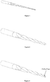
- the angles of the parallelogram are ground directly into the file and the acute and obtuse angles of the parallelogram-shaped cross section vary along the axis of the file ( Figure 4 ).
- Another variation of the parallelogram-shaped cross section contains C-shaped or concave geometries along one, two, three or four sides of the parallelogram ( Figure 5 ).
- the first approach which is disclosed for reference purposes, is a parallelogram-shaped cross section that has an axis of rotation that is centered such that the center of mass (centroid) is located at the axis of rotation.
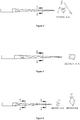
- the acute angle is different along the length of the file; preferably the acute angle is larger at the tip and decreases as it approaches the shank.
- the tip cross section has an acute angle of 70 degrees and decrease to an acute angle of 60 degrees as it approaches the shank ( Figure 6 ).
- the second approach which is in accordance with the present invention, is a parallelogram-shaped cross section that has an axis of rotation that is off-centered such that the center of mass (centroid) is not located at the axis of rotation.
- This is sometimes known as an asymmetric cross-section.
- the acute angle is different or the same along the length of the file. If the acute angle is different along the length of the file; preferably the acute angle is larger at the tip and decreases as it approaches the shank.
- the tip cross section has an acute angle of 80 degrees and decreases to an acute angle of 70 degrees as it approaches the shank ( Figure 7 ).
- the third embodiment which is disclosed for reference purposes, is a parallelogram-shaped cross section that has an axis of rotation that is centered such that the center of mass (centroid) is located at the axis of rotation and has 2 or 4 C-shaped or concave geometries along 2 symmetrical sides or all 4 sides of the cross section ( Figure 8 ).
- the acute angle is different or the same along the length of the file. If the acute angles are different along the length of the file, preferably the acute angle is larger at the tip and decreases as it approaches the shank.
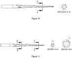
- the tip cross section has an acute angle of 80 degrees and decrease to an acute angle of 70 degrees as it approaches the shank ( Figure 9 ).
- the fourth approach which is in accordance with the present invention, is a parallelogram-shaped cross section that has a cross section which is off-centered such that the center of mass (centroid) is not located at the axis of rotation (asymmetric cross-section) and has 1, 2, 3 or 4 C-shaped or concave geometries along 1, 2, 3 or 4 sides of the parallelogram ( Figure 10 ).
- the acute angle is different or the same along the length of the file. If the acute angle is different along the length of the file; preferably the acute angle is larger at the tip and decreases as it approaches the shank.
- the tip cross section has an acute angle of 80 degrees and decrease to an acute angle of 70 degrees as it approaches the shank ( Figure 11 ).
- angles located proximate to the tip portion may be at least about 60 degrees and preferably at least about 65 degrees. Furthermore, the angle proximate to the tip portion may be less than about 85 degrees, and preferably less than about 80 degrees. For example, the angles located proximate to the tip portion may range from about 60 to about 85 degrees and preferably from about 65 to about 80 degrees. It is further contemplated that the angles located distally (toward the shank) from the tip portion may be at least about 40 degrees and preferably at least about 50 degrees. Furthermore, the angle located distally (toward the shank) from the tip portion may be less than about 85 degrees, and preferably less than about 80 degrees. For example, the angles located distally (toward the shank) from the tip portion may range from about 40 to about 85 degrees and preferably from about 50 to about 80 degrees.
- the lengths of the parallelogram may define various desirable ratios (e.g., from about 2:1 to about 1:4, from about 2:1 to about 1:2, from about 1:2 to about 1:1, from about 1:2 to about 4:5) of the helical angles between the acute angle helical angle and the obtuse angle helical angle, the helical angles between a first acute angle helical angle and an adjacent second acute angle helical angle, the helical angles between a first obtuse angle helical angle and an adjacent second obtuse angle helical angle, and/or the offset heights between the acute angle cutting edge and the obtuse angle cutting edge.
- ratios e.g., from about 2:1 to about 1:4, from about 2:1 to about 1:2, from about 1:2 to about 1:1, from about 1:2 to about 4:5
- the ratio of the lengths of the edges of the parallelogram may be about 1 (e.g., for the on center design) and/or, the ratio may range from about 1.6 to about 1.1 (e.g., for the off center parallelogram).
- the ratio of the acute angle helical angle and the obtuse angle helical angle may range from about 1.8 to about 1.2 (e.g., for the on center design) and/or the ratio may range from about 1.7 to about 1.1 (e.g., for the off center parallelogram).
- the offset heights between the acute angle cutting edge and obtuse angle cutting edge may vary from about 0.17mm to about 0.05mm (e.g., for the on center design), and/or the heights may vary from about 0.15mm to about 0.1mm (e.g., for the off center parallelogram).
- Superelastic materials are typically metal alloys which return to their original shape after substantial deformation. Examples of efforts in the art towards superelastic materials are found in U.S. Pat. No. 6,149,501 .
- the endodontic instruments disclosed above can be made of shape memory alloys (e.g., NiTi based, Cu based, Fe based, or combinations thereof) in their martensitic state of the present invention may provide more flexibility and increase fatigue resistance by optimized microstructure, which is particularly effective in shaping and cleaning canals with severe curvatures.
- shape memory alloys e.g., NiTi based, Cu based, Fe based, or combinations thereof
- Superelastic alloys such as nickel titanium (NiTi) or otherwise can withstand several times more strain than conventional materials, such as stainless steel, without becoming plastically deformed.
- This invention relates to dental instruments disclosed above. Specifically, this invention relates to endodontic rotary instruments for use in root canal cleaning and shaping procedures.
- the present invention provides an innovation of endodontic instrument that is made of shape memory alloys (SMA) such as Nickel-Titanium (NiTi) based systems, Cu based systems Fe based systems, or any combination thereof (e.g., materials selected from a group consisting of near-equiatomic Ni--Ti, Ni--Ti--Nb alloys, Ni--Ti--Fe alloys, Ni--Ti--Cu alloys, beta-phase titanium and combinations thereof).
- SMA shape memory alloys
- the present invention comprises rotary instruments made of NiTi Shape Memory Alloys, which provide one or more of the following novel aspects:
- martensite is the primary metallurgical phase in the present invention instrument, which is different from standard NiTi rotary instruments with predominant austenite structure at ambient temperature.
- austenite finish temperature (the final A.sub.f temperature measured by Differential Scanning calorimetry): the austenite finish temperature is preferably higher (e.g., at least about 3.degree. C.) than the ambient temperature (25.degree. C.); in contrast, most standard superelastic NiTi rotary instruments have austenite finish temperatures lower than ambient temperature.
- NiTi rotary instruments Due to higher austenite finish temperature, the present invention instrument would not return to the original complete straight state after being bent or deflected; in contrast, most standard superelastic NiTi rotary instruments can return to the original straight form via reverse phase transformation (martensite-to-austenite) upon unloading.
- Endodontic instruments made of NiTi shape memory alloys in their martensitic state have significantly improved overall performance than their austenitic counterparts (regular superelastic NiTi instruments), especially on flexibility and resistance against cyclic fatigue.
- the strength and cutting efficiency of endodontic instruments can also be improved by using ternary shape memory alloys NiTiX (X: Co, Cr, Fe, Nb, etc) based on the mechanism of alloy strengthening.
- the present invention instrument has essential and most desired characteristics for successful root canal surgery, including higher flexibility and lower stiffness, improved resistance to cyclic fatigue, higher degree of rotation against torsional fracture, more conforming to the shape of highly curved canals (less likely for ledging or perforation), and minimum possibility of instrument separation in comparison against conventional endodontic instruments made of NiTi shape memory alloy in superelastic condition with fully austenitic phase in microstructure.
- Example #1 (on center file designs): 30.06 ISO Tapered files were manufactured with parallelogram-shaped cross sections with constant angles (e.g., constant acute angles generally throughout the working portion of the file). Table 1 provides the measured cutting efficiency for the on center file designs of these tapered files with parallelogram-shaped cross sections with constant angles as compared to a triangle cross section ISO Tapered file (Vortex). As shown in Table 1 and Charts 1-3 for endodontic files having parallelogram-shaped cross sections with constant angles (generally throughout the working portion of the file), the smaller the parallelogram angle resulted in higher the void volume and higher cutting efficiency.
- the definition of void volume is the amount of free volume between the file and the canal wall.
- Example #2 (on center file designs): 30.06 ISO tapered files were manufactured with parallelogram-shaped cross sections with variable angles (e.g., variable acute angles, generally throughout the working portion of the file).
- Table 2 provides measured cutting efficiency for on center file designs of 30.06 ISO Tapered files, which were manufactured with parallelogram-shaped cross sections having variable angles as compared to a triangle cross section ISO Tapered file (Vortex).
- Figure 12 provides an example of one of the endodontic files having a parallelogram-shaped cross sections with variable angles (generally throughout the working portion of the file)
- endodontic files having parallelogram-shaped cross sections with variable angles results in higher cutting efficiency (with the exception of higher angles apically).
- larger cross section angles at the tip of the file may reduce void volume while providing more mass at the tip to increase the strength of the file (which reduces file breakage).
- endodontic files having parallelogram-shaped cross sections with variable angles include larger cross section angles at or towards the tip portion and lower cross section angles towards the shank.
- Example #3 (off center file designs): 30.06 ISO Tapered files were manufactured with parallelogram-shaped cross sections with constant angles and compared to a triangle cross section ISO Tapered file for cutting efficiency.
- FIG. 13 provides an example of one of the endodontic files (off center file design) having a parallelogram-shaped cross sections with constant angles (generally throughout the working portion of the file).
Description
- The present invention relates to endodontic instruments.
-
WO 99/37235 -
US2006228668 discloses a multi-tapered endodontic file formed from shaft of material having a shaft including a working portion including at least a first flute and a second flute, whereby the first flute is tapered along its length in accordance with a first predetermined taper function and the second flute is tapered along its length in accordance with a second predetermined taper function. -
EP1709934 discloses endodontic instruments having at least a section with a center of mass offset from an axis of rotation so that when the instrument is rotated, the section bends away from the axis of rotation. - Endodontic instruments can be used for cleaning and enlarging the endodontic cavity space ("ECS"), also known as the root canal system of a human tooth. The unprepared root canal is usually a narrow channel that runs through the central portion of the root of the tooth. Cleaning and enlargement of the ECS can be necessitated by the death or necrosis of the dental pulp, which is the tissue that occupies that space in a healthy tooth. This tissue can degenerate for a multitude of reasons, which include tooth decay, deep dental restorations, complete and incomplete dental fractures, traumatic injuries or spontaneous necrosis due to the calcification and ischemia of the tissue, which usually accompanies the ageing process. Similar to a necrotic or gangrenous appendix, the complete removal of this tissue is paramount, if not urgent, because of the subsequent development of infections or dental abscesses, septicemia, and even death.
- The root canal system of a human tooth is often narrow, curved and calcified, and can be extremely difficult to negotiate or clean. Indeed, the conventional endodontic or root canal instruments currently available are frequently inadequate in the complete removal of the pulp and the efficient enlargement of the ECS. Furthermore, they are usually predisposed to breakage, causing further destruction to the tooth. Broken instruments are usually difficult, if not impossible to remove, often necessitating the removal of the tooth. Injury to the tooth, which occurs as the result of a frank perforation or alteration of the natural anatomy of the ECS, can also lead to failure of the root canal and tooth loss.
- The unprepared root canal of the tooth usually begins as a narrow and relatively parallel channel. The portal of entry or the orifice and the portal of exit or foramen are relatively equal in diameter. To accommodate complete cleaning and filling of the canal and to prevent further infection, the canal must usually be prepared. The endodontic cavity preparation ("ECP") generally includes progressively enlarging the orifice and the body of the canal, while leaving the foramen relatively small. The result is usually a continuous cone-shaped preparation.
- In general, endodontic instruments are used to prepare the endodontic cavity space as described above. Endodontic instruments can include hand instruments and engine driven instruments. The latter can but need not be a rotary instrument. Combinations of both conventional hand and engine-driven rotary instruments are usually required to perform an ECP successfully and safely.
- An endodontic instrument may include a shaft that includes a tip and a shank. The endodontic instrument also includes grooves that spiral around the shaft. The grooves are referred to in the instant specification as flutes, (
Figure 1 ).
- The cross section of a file shows flutes (
Figure 2 ).
- The flutes are generally the spacing on both sides of a helical structure (or helix) that spirals around the shaft. The bottom portion of a flute--seen as a line or curve is referred to in the instant specification as a spline. The portion of a spline that comes into contact with a surface being cut during cutting will be referred to in the instant specification as a radial land.
- A flute of an endodontic instrument usually includes a sharpened edge configured for cutting. Cutting Edge of
Figure 3 is an example of such a cutting edge.
- Generally, an instrument having right-handed cutting edges is one that will cut or remove material when rotated clockwise, as viewed from shank to tip. In this specification, a direction of rotation will be specified as viewed from the shank to the tip of the instrument. The cut direction of rotation for a right handed endodontic instrument is clockwise. An instrument having left-handed cutting edges is one that will cut or remove material when rotated counter-clockwise. The cut direction of rotation, in this case, is counter-clockwise.
- An endodontic instrument includes a working portion, which is the portion that can cut or remove material. The working portion is typically the portion along the shaft that is between the tip of the instrument and the shank end of the flutes. The working portion is also referred to in this specification as the cutting portion, and the working length as the cutting or working length.
- Hand instruments are typically manufactured from metal wire blanks of varying sizes. The metallurgical properties of these wires, in general, have been engineered to produce a wide range of physical properties. These wires are usually then twisted or cut to produce specific shapes and styles. Examples of hand instruments include K-type, H-type, and R-type hand instruments. The barbed broach is manufactured from soft iron wire that is tapered and notched to form barbs or rasps along its surface. These instruments are generally used in the gross removal of pulp tissue or debris from the root canal system. Another R-type file is a rat-tail file.
- K-type instruments in current usage include reamers and K-files. K files are generally available in carbon steel, stainless steel, and more recently, an alloy of nickel-titanium. To fabricate a K-type instrument, a round wire of varying diameters is usually grounded into three or four-sided pyramidal blanks and then rotated or twisted into the appropriate shapes. These shapes are specified and controlled by the American National Standards Institute ("ANSI") and the International Standards Organization ("ISO"). The manufacturing processes for reamers and files are similar; except however, files usually have a greater number of flutes per unit length than reamers. Reamers are used in a rotational direction only, whereas files can be used in a rotational or push-pull fashion. Files made from three-sided or triangular blanks have smaller cross sectional areas than files made from four-sided blanks. Thus, these instruments are usually more flexible and less likely to fracture. They also can display larger clearance angles and are more efficient during debridement. Triangular files, therefore, are generally considered more desirable for hand instrumentation.
- H-type files are usually manufactured by grinding flutes into tapered round metal blanks to form a series of intersecting cones. H-type files can usually cut only in the pull direction (i.e., a pull stroke). Primarily because they have positive cutting angles, H-type files can be extremely efficient cutting instruments.
- Hand instruments are usually manufactured according to guidelines of the ANSI and the ISO, which specified that a working portion of an instrument be 16 mm in length. ANSI and ISO further specified that a first diameter or D.sub.1 of the instrument, be 1 mm from the tip or D.sub.0. Other ANSI and ISO specifications require that: instruments have a standard taper of 0.02 mm per mm along the working portion; the tip maintains a pyramidal shape no greater than 75 degree. in linear cross section; and hand instruments are available in 21, 25, and 31 mm lengths.
- In addition to the hand instruments described above, there are rotary instruments that are usually motor driven. G-type drills are usually available in carbon or stainless steel. As is typical, the G-type drill 300 shown includes a short flame-shaped head attached to a long shank. The flutes, in this instance, have U-shaped splines. The instrument includes cutting edges that have negative rake-angles. In general, a rake angle is the angle between the leading edge of a cutting tool and a perpendicular to the surface being cut. Rake angle is further described below. The flame-shaped head includes a non-cutting surface to prevent perforation. The instrument is usually used as a side-cutting instrument only. The instrument is relatively rigid and, therefore, may incur problem while used in a curved space, for example, the ECS.
- The present invention discloses endodontic instruments having derivatives of parallelogram-shaped cross sections in an attempt to overcome the deficiencies of predicate endodontic files as well as files of US patent
US4260379 , which discloses a preform parallelogram wire blank (spiral free) that is then twisted to create the spiral in the files. - The present invention seeks to improve upon prior root canal cleaning and/or enlarging systems by providing an improved rotatable endodontic file for cleaning/shaping a tooth root canal, comprising: an elongated shaft having a proximal end portion, a distal end and a tapered working portion having a rotational axis, the working portion extending from said proximal portion to said distal end; the external surface of said shaft working portion having a plurality of at least two spirals, a plurality of parallelogram-shaped cross sections along the working portion, each parallelogram-shaped cross section having an acute angle and an axis of rotation that is asymmetric such that the center of mass (centroid) is not located at the axis of rotation, wherein an acute angle of a first parallelogram-shaped cross section is the same or different than an acute angle of a second parallelogram-shaped cross section of the working portion, wherein the endodontic file is a constant tapered file.
- In another aspect, the present invention contemplates a rotatable endodontic file for cleaning/shaping a tooth root canal, comprising: an elongated shaft having a proximal end portion, a distal end and a tapered working portion having a rotational axis, the working portion extending from said proximal portion to said distal end; the external surface of said shaft working portion having a plurality of at least two spirals, a plurality of parallelogram-shaped cross sections that extend along the working portion, at least one of the parallelogram-shaped cross sections having one, two, three, or four C-shaped or concave geometries along one, two, three, or four sides, wherein each parallelogram-shaped cross section having an acute angle and a center of mass (centroid) is not located on the axis of rotation, and wherein an acute angle of a first parallelogram-shaped cross section is different or the same as an acute angle of a second parallelogram-shaped cross section, wherein the endodontic file is a constant tapered file.
- In yet another aspect, any of the aspects of the present invention may be further characterized by one or any combination of the following features: wherein the acute angle of the first parallelogram-shaped cross section is towards the proximal end and is larger than the acute angle of the second parallelogram-shaped cross section that is towards the distal end; wherein the acute angles range between 50 degrees and 85 degrees, wherein the endodontic file is composed of a material selected from the group consisting of a Nitinol based material, a Cu based material, a titanium based material and a stainless steel based material; wherein the material is processed by high temperature, cold temperatures and/or strain; wherein the acute angle of the first parallelogram-shaped cross section is larger towards the proximal end than the acute angle of the second parallelogram-shaped cross section towards the distal end; wherein the acute angles range between 50 degrees and 85 degrees; wherein the acute angles of the first and second parallelogram-shaped cross sections range between 50 degrees and 85 degrees; wherein the material is processed by high temperature from about 100° C to 600° C, 100° C to 480° C, or about 100° C to 180° C; wherein the material is processed by cold temperature from about -100° C to 10° C, -60° C to 10° C, or about 0° C to 10° C; wherein the material is processed by strain and/or stress from about 1% to 10%, from about 2% to 9%, or from about 2% to 8%; wherein the acute angles decrease from the proximal end to the distal end and range between 50 degrees and 85 degrees, wherein a plurality of acute angles towards the proximal end are larger than a plurality of acute angles towards the distal end; wherein the a plurality of acute angles towards the proximal end are the same while being different than a plurality of acute angles towards the distal end; wherein the endodontic file is a constant tapered file.
- An improved rotatable endodontic file for cleaning/shaping a tooth root canal, comprising: an elongated shaft having a proximal end portion, a distal end and a tapered working portion having a rotational axis, the working portion extending from said proximal portion to said distal end; the external surface of said shaft working portion having a plurality of at least two spirals, a plurality of parallelogram-shaped cross sections along the working portion, each parallelogram-shaped cross sections having an acute angle and an axis of rotation that is centered such that the cross section center of mass (centroid) is located at the axis of rotation, wherein an acute angle of a first parallelogram-shaped cross section is different from an acute angle of a second parallelogram-shaped cross section, is also disclosed.
- A rotatable endodontic file for cleaning/shaping a tooth root canal is also disclosed, comprising: an elongated shaft having a proximal end portion, a distal end and a tapered working portion having a rotational axis, the working portion extending from said proximal portion to said distal end; the external surface of said shaft working portion having a plurality of at least two spirals, a plurality of parallelogram-shaped cross sections along the working portion, at least one of the plurality of parallelogram-shaped cross sections two C-shaped or concave geometries along two symmetrical sides or four C-shaped or concave geometries along all four sides, each parallelogram-shaped cross section having an acute angle and a center of mass (centroid) that is located on the axis of rotation, each parallelogram-shaped cross section, wherein an acute angle of a first parallelogram-shaped cross section is different or the same as an acute angle of a second parallelogram-shaped cross section.
-
-
FIG. 1 is a perspective view of a first embodiment of an endodontic file of the present invention. -
FIG. 2 is a perspective view of a second embodiment of an endodontic file of the present invention. -
FIG. 3 is a perspective view of a third embodiment of an endodontic file of the present invention. -
FIG. 4 is a perspective view of a forth embodiment of an endodontic file of the present invention and a parallelogram-shaped cross section taken across A-A of the endodontic file. -
FIG. 5 is a perspective view of a fifth embodiment of an endodontic file of the present invention and a parallelogram-shaped cross section taken across A-A of the endodontic file -
FIG. 6 is a perspective view of a sixth embodiment of an endodontic file of the present invention and two parallelogram-shaped cross sections taken across A-A and B-B of the endodontic file. -
FIG. 7 is a perspective view of a seventh embodiment of an endodontic file of the present invention and two parallelogram-shaped cross sections taken across A-A and B-B of the endodontic file. -
FIG. 8 is a perspective view of a eighth embodiment of an endodontic file of the present invention and two parallelogram-shaped cross section taken across A-A of the endodontic file. -
FIG. 9 is a perspective view of a ninth embodiment of an endodontic file of the present invention and two parallelogram-shaped cross sections taken across A-A and B-B of the endodontic file. -
FIG. 10 is a perspective view of a tenth embodiment of an endodontic file of the present invention and two parallelogram-shaped cross section taken across A-A of the endodontic file. -
FIG. 11 is a perspective view of an eleventh embodiment of an endodontic file of the present invention and two parallelogram-shaped cross sections taken across A-A and B-B of the endodontic file. -
FIG. 12 is a perspective view of a twelfth embodiment of an endodontic file of the present invention and two parallelogram-shaped cross sections taken across A-A through O-O of the endodontic file -
FIG. 13 is a perspective view of an eleventh embodiment of an endodontic file of the present invention and two parallelogram-shaped cross sections taken across A-A through G-G of the endodontic file. - The invention discloses several novel approaches to parallelogram-shaped cross section and derivatives of parallelogram-shaped cross section for dental instruments (e.g., endodontic instruments such as endodontic files). In this invention, the angles of the parallelogram are ground directly into the file and the acute and obtuse angles of the parallelogram-shaped cross section vary along the axis of the file (
Figure 4 ).
- Another variation of the parallelogram-shaped cross section contains C-shaped or concave geometries along one, two, three or four sides of the parallelogram (
Figure 5 ).
- Several novel approaches to parallelogram-shaped cross sections and derivatives of parallelogram-shaped cross section for endodontic files are disclosed.
- The first approach, which is disclosed for reference purposes, is a parallelogram-shaped cross section that has an axis of rotation that is centered such that the center of mass (centroid) is located at the axis of rotation. In this embodiment the acute angle is different along the length of the file; preferably the acute angle is larger at the tip and decreases as it approaches the shank. For example, the tip cross section has an acute angle of 70 degrees and decrease to an acute angle of 60 degrees as it approaches the shank (
Figure 6 ).
- The second approach which is in accordance with the present invention, is a parallelogram-shaped cross section that has an axis of rotation that is off-centered such that the center of mass (centroid) is not located at the axis of rotation. This is sometimes known as an asymmetric cross-section. In this embodiment the acute angle is different or the same along the length of the file. If the acute angle is different along the length of the file; preferably the acute angle is larger at the tip and decreases as it approaches the shank. For example, the tip cross section has an acute angle of 80 degrees and decreases to an acute angle of 70 degrees as it approaches the shank (
Figure 7 ).
- The third embodiment, which is disclosed for reference purposes, is a parallelogram-shaped cross section that has an axis of rotation that is centered such that the center of mass (centroid) is located at the axis of rotation and has 2 or 4 C-shaped or concave geometries along 2 symmetrical sides or all 4 sides of the cross section (
Figure 8 ).
- In this embodiment the acute angle is different or the same along the length of the file. If the acute angles are different along the length of the file, preferably the acute angle is larger at the tip and decreases as it approaches the shank. For example, the tip cross section has an acute angle of 80 degrees and decrease to an acute angle of 70 degrees as it approaches the shank (
Figure 9 ).
- The fourth approach which is in accordance with the present invention, is a parallelogram-shaped cross section that has a cross section which is off-centered such that the center of mass (centroid) is not located at the axis of rotation (asymmetric cross-section) and has 1, 2, 3 or 4 C-shaped or concave geometries along 1, 2, 3 or 4 sides of the parallelogram (
Figure 10 ).
- In this embodiment the acute angle is different or the same along the length of the file. If the acute angle is different along the length of the file; preferably the acute angle is larger at the tip and decreases as it approaches the shank. For example, the tip cross section has an acute angle of 80 degrees and decrease to an acute angle of 70 degrees as it approaches the shank (
Figure 11 ).
- It is contemplated that the angles located proximate to the tip portion may be at least about 60 degrees and preferably at least about 65 degrees. Furthermore, the angle proximate to the tip portion may be less than about 85 degrees, and preferably less than about 80 degrees. For example, the angles located proximate to the tip portion may range from about 60 to about 85 degrees and preferably from about 65 to about 80 degrees. It is further contemplated that the angles located distally (toward the shank) from the tip portion may be at least about 40 degrees and preferably at least about 50 degrees. Furthermore, the angle located distally (toward the shank) from the tip portion may be less than about 85 degrees, and preferably less than about 80 degrees. For example, the angles located distally (toward the shank) from the tip portion may range from about 40 to about 85 degrees and preferably from about 50 to about 80 degrees.
- The lengths of the parallelogram (both on center and off center) may define various desirable ratios (e.g., from about 2:1 to about 1:4, from about 2:1 to about 1:2, from about 1:2 to about 1:1, from about 1:2 to about 4:5) of the helical angles between the acute angle helical angle and the obtuse angle helical angle, the helical angles between a first acute angle helical angle and an adjacent second acute angle helical angle, the helical angles between a first obtuse angle helical angle and an adjacent second obtuse angle helical angle, and/or the offset heights between the acute angle cutting edge and the obtuse angle cutting edge. It is appreciated that in one embodiment, the ratio of the lengths of the edges of the parallelogram may be about 1 (e.g., for the on center design) and/or, the ratio may range from about 1.6 to about 1.1 (e.g., for the off center parallelogram).
- In another embodiment, the ratio of the acute angle helical angle and the obtuse angle helical angle may range from about 1.8 to about 1.2 (e.g., for the on center design) and/or the ratio may range from about 1.7 to about 1.1 (e.g., for the off center parallelogram).
- In yet another embodiment, the offset heights between the acute angle cutting edge and obtuse angle cutting edge may vary from about 0.17mm to about 0.05mm (e.g., for the on center design), and/or the heights may vary from about 0.15mm to about 0.1mm (e.g., for the off center parallelogram).
- Superelastic materials are typically metal alloys which return to their original shape after substantial deformation. Examples of efforts in the art towards superelastic materials are found in
U.S. Pat. No. 6,149,501 . - The endodontic instruments disclosed above can be made of shape memory alloys (e.g., NiTi based, Cu based, Fe based, or combinations thereof) in their martensitic state of the present invention may provide more flexibility and increase fatigue resistance by optimized microstructure, which is particularly effective in shaping and cleaning canals with severe curvatures. Superelastic alloys such as nickel titanium (NiTi) or otherwise can withstand several times more strain than conventional materials, such as stainless steel, without becoming plastically deformed.
- This invention relates to dental instruments disclosed above. Specifically, this invention relates to endodontic rotary instruments for use in root canal cleaning and shaping procedures. The present invention provides an innovation of endodontic instrument that is made of shape memory alloys (SMA) such as Nickel-Titanium (NiTi) based systems, Cu based systems Fe based systems, or any combination thereof (e.g., materials selected from a group consisting of near-equiatomic Ni--Ti, Ni--Ti--Nb alloys, Ni--Ti--Fe alloys, Ni--Ti--Cu alloys, beta-phase titanium and combinations thereof).
- The present invention comprises rotary instruments made of NiTi Shape Memory Alloys, which provide one or more of the following novel aspects:
- Primary metallurgical phase in microstructure: martensite is the primary metallurgical phase in the present invention instrument, which is different from standard NiTi rotary instruments with predominant austenite structure at ambient temperature.
- Higher austenite finish temperature (the final A.sub.f temperature measured by Differential Scanning calorimetry): the austenite finish temperature is preferably higher (e.g., at least about 3.degree. C.) than the ambient temperature (25.degree. C.); in contrast, most standard superelastic NiTi rotary instruments have austenite finish temperatures lower than ambient temperature.
- Due to higher austenite finish temperature, the present invention instrument would not return to the original complete straight state after being bent or deflected; in contrast, most standard superelastic NiTi rotary instruments can return to the original straight form via reverse phase transformation (martensite-to-austenite) upon unloading.
- Endodontic instruments made of NiTi shape memory alloys in their martensitic state have significantly improved overall performance than their austenitic counterparts (regular superelastic NiTi instruments), especially on flexibility and resistance against cyclic fatigue.
- The strength and cutting efficiency of endodontic instruments can also be improved by using ternary shape memory alloys NiTiX (X: Co, Cr, Fe, Nb, etc) based on the mechanism of alloy strengthening.
- Specifically, the present invention instrument has essential and most desired characteristics for successful root canal surgery, including higher flexibility and lower stiffness, improved resistance to cyclic fatigue, higher degree of rotation against torsional fracture, more conforming to the shape of highly curved canals (less likely for ledging or perforation), and minimum possibility of instrument separation in comparison against conventional endodontic instruments made of NiTi shape memory alloy in superelastic condition with fully austenitic phase in microstructure.
- Example #1 (on center file designs): 30.06 ISO Tapered files were manufactured with parallelogram-shaped cross sections with constant angles (e.g., constant acute angles generally throughout the working portion of the file). Table 1 provides the measured cutting efficiency for the on center file designs of these tapered files with parallelogram-shaped cross sections with constant angles as compared to a triangle cross section ISO Tapered file (Vortex).


 As shown in Table 1 and Charts 1-3 for endodontic files having parallelogram-shaped cross sections with constant angles (generally throughout the working portion of the file), the smaller the parallelogram angle resulted in higher the void volume and higher cutting efficiency. The definition of void volume is the amount of free volume between the file and the canal wall.
- Example #2 (on center file designs): 30.06 ISO tapered files were manufactured with parallelogram-shaped cross sections with variable angles (e.g., variable acute angles, generally throughout the working portion of the file). Table 2 provides measured cutting efficiency for on center file designs of 30.06 ISO Tapered files, which were manufactured with parallelogram-shaped cross sections having variable angles as compared to a triangle cross section ISO Tapered file (Vortex).
Figure 12 provides an example of one of the endodontic files having a parallelogram-shaped cross sections with variable angles (generally throughout the working portion of the file)

- As shown in Table 2: for endodontic files having parallelogram-shaped cross sections with variable angles (generally throughout the working portion of the file), larger cross section angles results in higher cutting efficiency (with the exception of higher angles apically). Furthermore, it is appreciated that larger cross section angles at the tip of the file may reduce void volume while providing more mass at the tip to increase the strength of the file (which reduces file breakage). Desirably, endodontic files having parallelogram-shaped cross sections with variable angles (generally throughout the working portion of the file) include larger cross section angles at or towards the tip portion and lower cross section angles towards the shank.
- Example #3 (off center file designs): 30.06 ISO Tapered files were manufactured with parallelogram-shaped cross sections with constant angles and compared to a triangle cross section ISO Tapered file for cutting efficiency.


- As shown in Charts 4-5 for off center file designs of 30.06 ISO Tapered files, which were manufactured with parallelogram-shaped cross sections having constant angles, smaller cross section angles results in higher cutting efficiency and higher void volume.
Figure 13 provides an example of one of the endodontic files (off center file design) having a parallelogram-shaped cross sections with constant angles (generally throughout the working portion of the file). - Examples of efforts in the art directed to methods of manufacturing endodontic instruments may be found in, but not limited to
U.S. Patent Application 20110271529 .
Claims (12)
- A rotatable endodontic file for cleaning/shaping a tooth root canal, comprising: an elongated shaft having a proximal end portion, a distal end and a tapered working portion having a rotational axis, the working portion extending from said proximal portion to said distal end; the external surface of said shaft working portion having a plurality of at least two spirals, a plurality of parallelogram-shaped cross sections (A-A to O-O) along the working portion, each parallelogram-shaped cross section (A-A to O-O) having an acute angle and an axis of rotation that is asymmetric such that the center of mass is not located at the axis of rotation, wherein an acute angle of a first parallelogram-shaped cross section (A-A) is the same or different than an acute angle of a second parallelogram-shaped cross section (B-B) of the working portion,
wherein the endodontic file is a constant tapered file. - An endodontic file according to claim 1, wherein the acute angle of the first parallelogram-shaped cross section (A-A) is larger towards the proximal end than the acute angle of the second parallelogram-shaped cross section (B-B) towards the distal end.
- An endodontic file according to claim 2, wherein the acute angles range between 50 degrees and 85 degrees.
- An endodontic file according to claim 1 wherein the acute angles range between 50 degrees and 85 degrees.
- An endodontic file according to claims 1, 2 , 3 and 4 is composed of a material selected from the group consisting of a Nitinol based material, Cu based material, titanium based material and a stainless steel based material.
- An endodontic file according to claim 5, wherein the material is processed by high temperature, cold temperatures and/or strain.
- A rotatable endodontic file for cleaning/shaping a tooth root canal, comprising: an elongated shaft having a proximal end portion, a distal end and a tapered working portion having a rotational axis, the working portion extending from said proximal portion to said distal end; the external surface of said shaft working portion having a plurality of at least two spirals, a plurality of parallelogram-shaped cross sections (A-A to O-O) that extend along the working portion, at least one of the parallelogram-shaped cross sections (A-A to O-O) having one, two, three, or four C-shaped or concave geometries along one, two, three, or four sides, wherein each parallelogram-shaped cross section (A-A to O-O) having an acute angle and a center of mass is not located on the axis of rotation, and wherein an acute angle of a first parallelogram-shaped cross section (A-A) is different or the same as an acute angle of a second parallelogram-shaped cross section (B-B),
wherein the endodontic file is a constant tapered file. - An endodontic file according to claim 7, wherein the acute angle of the first parallelogram-shaped cross section (A-A) is larger towards the proximal end than the acute angle of the second parallelogram-shaped cross section (B-B) towards the distal end.
- An endodontic file according to claim 8 wherein the acute angles of the first and second parallelogram-shaped cross section (A-A and B-B) range between 50 degrees and 85 degrees.
- An endodontic file according to claim 7 wherein the acute angles of the first and second parallelogram-shaped cross section (A-A and B-B) range between 50 degrees and 85 degrees.
- An endodontic file according to claims 7, 8, 9 and 10 is composed of a material selected from the group consisting of a Nitinol based material, Cu based material, titanium based material and a stainless steel based material.
- An endodontic file according to claim 11 wherein the material is processed by high temperature, cold temperatures and/or strain.
Applications Claiming Priority (2)
| Application Number | Priority Date | Filing Date | Title |
|---|---|---|---|
| US201361837312P | 2013-06-20 | 2013-06-20 | |
| PCT/US2014/043515 WO2014205411A2 (en) | 2013-06-20 | 2014-06-20 | Endodontic instruments |
Publications (2)
| Publication Number | Publication Date |
|---|---|
| EP3010439A2 EP3010439A2 (en) | 2016-04-27 |
| EP3010439B1 true EP3010439B1 (en) | 2019-03-20 |
Family
ID=52105539
Family Applications (1)
| Application Number | Title | Priority Date | Filing Date |
|---|---|---|---|
| EP14742026.9A Active EP3010439B1 (en) | 2013-06-20 | 2014-06-20 | Endodontic instruments |
Country Status (5)
| Country | Link |
|---|---|
| US (2) | US9901418B2 (en) |
| EP (1) | EP3010439B1 (en) |
| JP (1) | JP6370373B2 (en) |
| CA (1) | CA2916467C (en) |
| WO (1) | WO2014205411A2 (en) |
Families Citing this family (7)
| Publication number | Priority date | Publication date | Assignee | Title |
|---|---|---|---|---|
| WO2014118587A1 (en) * | 2013-01-30 | 2014-08-07 | Maillefer Instruments Holding Sàrl | Instrument for boring dental root canals |
| US10543060B2 (en) | 2015-12-03 | 2020-01-28 | Ormco Corporation | Fluted endodontic file |
| USD842474S1 (en) | 2017-10-20 | 2019-03-05 | Ormco Corporation | Endodontic file |
| JP2021029540A (en) * | 2019-08-22 | 2021-03-01 | マニー株式会社 | Dental root canal treatment tool |
| JP7143262B2 (en) | 2019-08-22 | 2022-09-28 | マニー株式会社 | dental root canal instrument |
| JP2022030793A (en) | 2020-08-07 | 2022-02-18 | マニー株式会社 | Dental file |
| DE102020128671B4 (en) | 2020-10-30 | 2023-02-02 | Gebr. Brasseler Gmbh & Co. Kg | root canal instrument |
Family Cites Families (25)
| Publication number | Priority date | Publication date | Assignee | Title |
|---|---|---|---|---|
| US4260379A (en) * | 1979-05-17 | 1981-04-07 | Sybron Corporation | Endodontic instrument |
| US4611508A (en) * | 1983-02-08 | 1986-09-16 | Roane James B | Endodontic instrument |
| US4443193A (en) * | 1983-02-08 | 1984-04-17 | Roane James B | Endodontic instrument |
| US5762497A (en) * | 1996-03-07 | 1998-06-09 | Tulsa Dental Products | Endodontic dental instrument |
| US5984679A (en) * | 1997-09-26 | 1999-11-16 | Ormco Corporation | Method of manufacturing superelastic endodontic files and files made therefrom |
| US6149501A (en) * | 1997-09-26 | 2000-11-21 | Kerr Corporation | Superelastic endodontic instrument, method of manufacture, and apparatus therefor |
| US6299445B1 (en) * | 1999-04-08 | 2001-10-09 | Ormco Corporation | Endodontic instrument, instrument blank and method of manufacture |
| JP4214285B2 (en) * | 1999-12-17 | 2009-01-28 | マニー株式会社 | Dental root canal treatment instrument and manufacturing method thereof |
| JP4214286B2 (en) * | 2000-01-05 | 2009-01-28 | マニー株式会社 | Dental root canal treatment instrument and manufacturing method thereof |
| US6966774B2 (en) * | 2001-08-16 | 2005-11-22 | Cloudland Institute, Llc. | Endodontic instrument having notched cutting surfaces |
| US6712611B2 (en) * | 2001-10-05 | 2004-03-30 | Ormco Corporation | Endodontic instrument with controlled flexibility and method of manufacturing same |
| US6783438B2 (en) * | 2002-04-18 | 2004-08-31 | Ormco Corporation | Method of manufacturing an endodontic instrument |
| DE10233030B3 (en) * | 2002-07-20 | 2004-02-19 | Gebr. Brasseler Gmbh & Co. Kg | Root canal instrument |
| JP4247345B2 (en) * | 2002-11-20 | 2009-04-02 | マニー株式会社 | Method for manufacturing dental root canal treatment instrument |
| US7955078B2 (en) * | 2003-05-01 | 2011-06-07 | Scianamblo Michael J | Endodontic instruments for preparing endodontic cavity spaces |
| US7094056B2 (en) * | 2003-05-01 | 2006-08-22 | Scianamblo Michael J | Endodontic instrument having reversed helix |
| US20080213720A1 (en) * | 2003-05-13 | 2008-09-04 | Ultradent Products, Inc. | Endodontic instruments manufactured using chemical milling |
| US7731498B2 (en) * | 2003-05-16 | 2010-06-08 | Mcspadden John T | Endododontic file with multi-tapered flutes |
| DE602006020949D1 (en) * | 2005-04-08 | 2011-05-12 | Michael J Scianamblo | Bending endodontic instruments |
| US7766657B2 (en) * | 2005-08-09 | 2010-08-03 | Andris Jaunberzins | Endodontic file combining active and passive cutting edges |
| US20100167243A1 (en) * | 2008-12-31 | 2010-07-01 | Anton Spiridonov | System and method for automatic construction of realistic looking tooth roots |
| JP5547711B2 (en) * | 2009-02-27 | 2014-07-16 | マニー株式会社 | Gutta-percha remover |
| WO2014118587A1 (en) * | 2013-01-30 | 2014-08-07 | Maillefer Instruments Holding Sàrl | Instrument for boring dental root canals |
| US20170135786A1 (en) * | 2013-07-18 | 2017-05-18 | Andris Jaunberzins | Endodontic Instrument With Narrow Radial Lands |
| US20150024342A1 (en) * | 2013-07-18 | 2015-01-22 | Andris Jaunberzins | Endodontic Instrument With Narrow Radial Lands |
-
2014
- 2014-06-20 CA CA2916467A patent/CA2916467C/en active Active
- 2014-06-20 EP EP14742026.9A patent/EP3010439B1/en active Active
- 2014-06-20 JP JP2016521869A patent/JP6370373B2/en active Active
- 2014-06-20 US US14/311,134 patent/US9901418B2/en active Active
- 2014-06-20 WO PCT/US2014/043515 patent/WO2014205411A2/en active Application Filing
-
2018
- 2018-01-15 US US15/871,523 patent/US10966801B2/en active Active
Non-Patent Citations (1)
| Title |
|---|
| None * |
Also Published As
| Publication number | Publication date |
|---|---|
| US10966801B2 (en) | 2021-04-06 |
| WO2014205411A2 (en) | 2014-12-24 |
| CA2916467C (en) | 2018-09-11 |
| US9901418B2 (en) | 2018-02-27 |
| US20150216624A1 (en) | 2015-08-06 |
| EP3010439A2 (en) | 2016-04-27 |
| WO2014205411A3 (en) | 2015-06-04 |
| CA2916467A1 (en) | 2014-12-24 |
| US20180325624A1 (en) | 2018-11-15 |
| JP6370373B2 (en) | 2018-08-08 |
| JP2016523637A (en) | 2016-08-12 |
Similar Documents
| Publication | Publication Date | Title |
|---|---|---|
| EP3010439B1 (en) | Endodontic instruments | |
| US7094056B2 (en) | Endodontic instrument having reversed helix | |
| US7955078B2 (en) | Endodontic instruments for preparing endodontic cavity spaces | |
| US8182265B2 (en) | Endodontic instrument with multi-tapered flutes | |
| CA2931240C (en) | Endodontic instruments formed from or coated with a porous material | |
| EP3777751B1 (en) | Dental file | |
| WO2015009814A1 (en) | Endodontic instrument with narrow radial lands | |
| JP2002537892A (en) | Non-circular endodontic instruments | |
| EP1716818B1 (en) | Endodontic files and reamers | |
| US10561475B2 (en) | Non-circular endodontic instruments | |
| US20170135786A1 (en) | Endodontic Instrument With Narrow Radial Lands | |
| WO2023172494A1 (en) | Endodontic instrument with enlarged chip space and reduced torque strength | |
| Kalita et al. | Rotary Endodontics–a Review |
Legal Events
| Date | Code | Title | Description |
|---|---|---|---|
| PUAI | Public reference made under article 153(3) epc to a published international application that has entered the european phase |
Free format text: ORIGINAL CODE: 0009012 |
|
| 17P | Request for examination filed |
Effective date: 20151217 |
|
| AK | Designated contracting states |
Kind code of ref document: A2 Designated state(s): AL AT BE BG CH CY CZ DE DK EE ES FI FR GB GR HR HU IE IS IT LI LT LU LV MC MK MT NL NO PL PT RO RS SE SI SK SM TR |
|
| AX | Request for extension of the european patent |
Extension state: BA ME |
|
| DAX | Request for extension of the european patent (deleted) | ||
| STAA | Information on the status of an ep patent application or granted ep patent |
Free format text: STATUS: EXAMINATION IS IN PROGRESS |
|
| 17Q | First examination report despatched |
Effective date: 20170818 |
|
| RAP1 | Party data changed (applicant data changed or rights of an application transferred) |
Owner name: DENTSPLY SIRONA INC. |
|
| REG | Reference to a national code |
Ref country code: DE Ref legal event code: R079 Ref document number: 602014043249 Country of ref document: DE Free format text: PREVIOUS MAIN CLASS: A61C0005020000 Ipc: A61C0005420000 |
|
| RIC1 | Information provided on ipc code assigned before grant |
Ipc: A61C 5/42 20170101AFI20180711BHEP |
|
| GRAP | Despatch of communication of intention to grant a patent |
Free format text: ORIGINAL CODE: EPIDOSNIGR1 |
|
| STAA | Information on the status of an ep patent application or granted ep patent |
Free format text: STATUS: GRANT OF PATENT IS INTENDED |
|
| INTG | Intention to grant announced |
Effective date: 20181018 |
|
| GRAS | Grant fee paid |
Free format text: ORIGINAL CODE: EPIDOSNIGR3 |
|
| RIC1 | Information provided on ipc code assigned before grant |
Ipc: A61C 5/42 20170101AFI20180711BHEP |
|
| GRAA | (expected) grant |
Free format text: ORIGINAL CODE: 0009210 |
|
| STAA | Information on the status of an ep patent application or granted ep patent |
Free format text: STATUS: THE PATENT HAS BEEN GRANTED |
|
| REG | Reference to a national code |
Ref country code: DE Ref legal event code: R082 Ref document number: 602014043249 Country of ref document: DE Representative=s name: WAECHTERSHAEUSER & HARTZ PATENTANWALTSPARTNERS, DE |
|
| AK | Designated contracting states |
Kind code of ref document: B1 Designated state(s): AL AT BE BG CH CY CZ DE DK EE ES FI FR GB GR HR HU IE IS IT LI LT LU LV MC MK MT NL NO PL PT RO RS SE SI SK SM TR |
|
| REG | Reference to a national code |
Ref country code: GB Ref legal event code: FG4D |
|
| REG | Reference to a national code |
Ref country code: CH Ref legal event code: EP |
|
| REG | Reference to a national code |
Ref country code: DE Ref legal event code: R096 Ref document number: 602014043249 Country of ref document: DE |
|
| REG | Reference to a national code |
Ref country code: AT Ref legal event code: REF Ref document number: 1109705 Country of ref document: AT Kind code of ref document: T Effective date: 20190415 |
|
| REG | Reference to a national code |
Ref country code: IE Ref legal event code: FG4D |
|
| REG | Reference to a national code |
Ref country code: SE Ref legal event code: TRGR |
|
| REG | Reference to a national code |
Ref country code: NL Ref legal event code: MP Effective date: 20190320 |
|
| PG25 | Lapsed in a contracting state [announced via postgrant information from national office to epo] |
Ref country code: LT Free format text: LAPSE BECAUSE OF FAILURE TO SUBMIT A TRANSLATION OF THE DESCRIPTION OR TO PAY THE FEE WITHIN THE PRESCRIBED TIME-LIMIT Effective date: 20190320 Ref country code: FI Free format text: LAPSE BECAUSE OF FAILURE TO SUBMIT A TRANSLATION OF THE DESCRIPTION OR TO PAY THE FEE WITHIN THE PRESCRIBED TIME-LIMIT Effective date: 20190320 Ref country code: NO Free format text: LAPSE BECAUSE OF FAILURE TO SUBMIT A TRANSLATION OF THE DESCRIPTION OR TO PAY THE FEE WITHIN THE PRESCRIBED TIME-LIMIT Effective date: 20190620 |
|
| REG | Reference to a national code |
Ref country code: LT Ref legal event code: MG4D |
|
| PG25 | Lapsed in a contracting state [announced via postgrant information from national office to epo] |
Ref country code: GR Free format text: LAPSE BECAUSE OF FAILURE TO SUBMIT A TRANSLATION OF THE DESCRIPTION OR TO PAY THE FEE WITHIN THE PRESCRIBED TIME-LIMIT Effective date: 20190621 Ref country code: BG Free format text: LAPSE BECAUSE OF FAILURE TO SUBMIT A TRANSLATION OF THE DESCRIPTION OR TO PAY THE FEE WITHIN THE PRESCRIBED TIME-LIMIT Effective date: 20190620 Ref country code: HR Free format text: LAPSE BECAUSE OF FAILURE TO SUBMIT A TRANSLATION OF THE DESCRIPTION OR TO PAY THE FEE WITHIN THE PRESCRIBED TIME-LIMIT Effective date: 20190320 Ref country code: RS Free format text: LAPSE BECAUSE OF FAILURE TO SUBMIT A TRANSLATION OF THE DESCRIPTION OR TO PAY THE FEE WITHIN THE PRESCRIBED TIME-LIMIT Effective date: 20190320 Ref country code: LV Free format text: LAPSE BECAUSE OF FAILURE TO SUBMIT A TRANSLATION OF THE DESCRIPTION OR TO PAY THE FEE WITHIN THE PRESCRIBED TIME-LIMIT Effective date: 20190320 Ref country code: NL Free format text: LAPSE BECAUSE OF FAILURE TO SUBMIT A TRANSLATION OF THE DESCRIPTION OR TO PAY THE FEE WITHIN THE PRESCRIBED TIME-LIMIT Effective date: 20190320 |
|
| REG | Reference to a national code |
Ref country code: AT Ref legal event code: MK05 Ref document number: 1109705 Country of ref document: AT Kind code of ref document: T Effective date: 20190320 |
|
| PG25 | Lapsed in a contracting state [announced via postgrant information from national office to epo] |
Ref country code: RO Free format text: LAPSE BECAUSE OF FAILURE TO SUBMIT A TRANSLATION OF THE DESCRIPTION OR TO PAY THE FEE WITHIN THE PRESCRIBED TIME-LIMIT Effective date: 20190320 Ref country code: SK Free format text: LAPSE BECAUSE OF FAILURE TO SUBMIT A TRANSLATION OF THE DESCRIPTION OR TO PAY THE FEE WITHIN THE PRESCRIBED TIME-LIMIT Effective date: 20190320 Ref country code: CZ Free format text: LAPSE BECAUSE OF FAILURE TO SUBMIT A TRANSLATION OF THE DESCRIPTION OR TO PAY THE FEE WITHIN THE PRESCRIBED TIME-LIMIT Effective date: 20190320 Ref country code: ES Free format text: LAPSE BECAUSE OF FAILURE TO SUBMIT A TRANSLATION OF THE DESCRIPTION OR TO PAY THE FEE WITHIN THE PRESCRIBED TIME-LIMIT Effective date: 20190320 Ref country code: AL Free format text: LAPSE BECAUSE OF FAILURE TO SUBMIT A TRANSLATION OF THE DESCRIPTION OR TO PAY THE FEE WITHIN THE PRESCRIBED TIME-LIMIT Effective date: 20190320 Ref country code: PT Free format text: LAPSE BECAUSE OF FAILURE TO SUBMIT A TRANSLATION OF THE DESCRIPTION OR TO PAY THE FEE WITHIN THE PRESCRIBED TIME-LIMIT Effective date: 20190720 Ref country code: EE Free format text: LAPSE BECAUSE OF FAILURE TO SUBMIT A TRANSLATION OF THE DESCRIPTION OR TO PAY THE FEE WITHIN THE PRESCRIBED TIME-LIMIT Effective date: 20190320 |
|
| PG25 | Lapsed in a contracting state [announced via postgrant information from national office to epo] |
Ref country code: SM Free format text: LAPSE BECAUSE OF FAILURE TO SUBMIT A TRANSLATION OF THE DESCRIPTION OR TO PAY THE FEE WITHIN THE PRESCRIBED TIME-LIMIT Effective date: 20190320 Ref country code: PL Free format text: LAPSE BECAUSE OF FAILURE TO SUBMIT A TRANSLATION OF THE DESCRIPTION OR TO PAY THE FEE WITHIN THE PRESCRIBED TIME-LIMIT Effective date: 20190320 |
|
| PG25 | Lapsed in a contracting state [announced via postgrant information from national office to epo] |
Ref country code: IS Free format text: LAPSE BECAUSE OF FAILURE TO SUBMIT A TRANSLATION OF THE DESCRIPTION OR TO PAY THE FEE WITHIN THE PRESCRIBED TIME-LIMIT Effective date: 20190720 Ref country code: AT Free format text: LAPSE BECAUSE OF FAILURE TO SUBMIT A TRANSLATION OF THE DESCRIPTION OR TO PAY THE FEE WITHIN THE PRESCRIBED TIME-LIMIT Effective date: 20190320 |
|
| REG | Reference to a national code |
Ref country code: DE Ref legal event code: R097 Ref document number: 602014043249 Country of ref document: DE |
|
| PLBE | No opposition filed within time limit |
Free format text: ORIGINAL CODE: 0009261 |
|
| STAA | Information on the status of an ep patent application or granted ep patent |
Free format text: STATUS: NO OPPOSITION FILED WITHIN TIME LIMIT |
|
| PG25 | Lapsed in a contracting state [announced via postgrant information from national office to epo] |
Ref country code: MC Free format text: LAPSE BECAUSE OF FAILURE TO SUBMIT A TRANSLATION OF THE DESCRIPTION OR TO PAY THE FEE WITHIN THE PRESCRIBED TIME-LIMIT Effective date: 20190320 Ref country code: DK Free format text: LAPSE BECAUSE OF FAILURE TO SUBMIT A TRANSLATION OF THE DESCRIPTION OR TO PAY THE FEE WITHIN THE PRESCRIBED TIME-LIMIT Effective date: 20190320 |
|
| 26N | No opposition filed |
Effective date: 20200102 |
|
| PG25 | Lapsed in a contracting state [announced via postgrant information from national office to epo] |
Ref country code: SI Free format text: LAPSE BECAUSE OF FAILURE TO SUBMIT A TRANSLATION OF THE DESCRIPTION OR TO PAY THE FEE WITHIN THE PRESCRIBED TIME-LIMIT Effective date: 20190320 |
|
| REG | Reference to a national code |
Ref country code: BE Ref legal event code: MM Effective date: 20190630 |
|
| PG25 | Lapsed in a contracting state [announced via postgrant information from national office to epo] |
Ref country code: TR Free format text: LAPSE BECAUSE OF FAILURE TO SUBMIT A TRANSLATION OF THE DESCRIPTION OR TO PAY THE FEE WITHIN THE PRESCRIBED TIME-LIMIT Effective date: 20190320 |
|
| PG25 | Lapsed in a contracting state [announced via postgrant information from national office to epo] |
Ref country code: IE Free format text: LAPSE BECAUSE OF NON-PAYMENT OF DUE FEES Effective date: 20190620 |
|
| PG25 | Lapsed in a contracting state [announced via postgrant information from national office to epo] |
Ref country code: BE Free format text: LAPSE BECAUSE OF NON-PAYMENT OF DUE FEES Effective date: 20190630 Ref country code: LU Free format text: LAPSE BECAUSE OF NON-PAYMENT OF DUE FEES Effective date: 20190620 |
|
| PG25 | Lapsed in a contracting state [announced via postgrant information from national office to epo] |
Ref country code: CY Free format text: LAPSE BECAUSE OF FAILURE TO SUBMIT A TRANSLATION OF THE DESCRIPTION OR TO PAY THE FEE WITHIN THE PRESCRIBED TIME-LIMIT Effective date: 20190320 |
|
| PG25 | Lapsed in a contracting state [announced via postgrant information from national office to epo] |
Ref country code: HU Free format text: LAPSE BECAUSE OF FAILURE TO SUBMIT A TRANSLATION OF THE DESCRIPTION OR TO PAY THE FEE WITHIN THE PRESCRIBED TIME-LIMIT; INVALID AB INITIO Effective date: 20140620 Ref country code: MT Free format text: LAPSE BECAUSE OF FAILURE TO SUBMIT A TRANSLATION OF THE DESCRIPTION OR TO PAY THE FEE WITHIN THE PRESCRIBED TIME-LIMIT Effective date: 20190320 |
|
| PG25 | Lapsed in a contracting state [announced via postgrant information from national office to epo] |
Ref country code: MK Free format text: LAPSE BECAUSE OF FAILURE TO SUBMIT A TRANSLATION OF THE DESCRIPTION OR TO PAY THE FEE WITHIN THE PRESCRIBED TIME-LIMIT Effective date: 20190320 |
|
| PGFP | Annual fee paid to national office [announced via postgrant information from national office to epo] |
Ref country code: IT Payment date: 20230510 Year of fee payment: 10 Ref country code: FR Payment date: 20230510 Year of fee payment: 10 Ref country code: DE Payment date: 20230502 Year of fee payment: 10 |
|
| PGFP | Annual fee paid to national office [announced via postgrant information from national office to epo] |
Ref country code: SE Payment date: 20230510 Year of fee payment: 10 |
|
| PGFP | Annual fee paid to national office [announced via postgrant information from national office to epo] |
Ref country code: GB Payment date: 20230504 Year of fee payment: 10 Ref country code: CH Payment date: 20230702 Year of fee payment: 10 |