EP3010123A1 - Magnet fracturing device - Google Patents
Magnet fracturing device Download PDFInfo
- Publication number
- EP3010123A1 EP3010123A1 EP14810548.9A EP14810548A EP3010123A1 EP 3010123 A1 EP3010123 A1 EP 3010123A1 EP 14810548 A EP14810548 A EP 14810548A EP 3010123 A1 EP3010123 A1 EP 3010123A1
- Authority
- EP
- European Patent Office
- Prior art keywords
- magnet
- supporting
- pair
- portions
- supporting tool
- Prior art date
- Legal status (The legal status is an assumption and is not a legal conclusion. Google has not performed a legal analysis and makes no representation as to the accuracy of the status listed.)
- Granted
Links
Images





Classifications
-
- B—PERFORMING OPERATIONS; TRANSPORTING
- B26—HAND CUTTING TOOLS; CUTTING; SEVERING
- B26F—PERFORATING; PUNCHING; CUTTING-OUT; STAMPING-OUT; SEVERING BY MEANS OTHER THAN CUTTING
- B26F3/00—Severing by means other than cutting; Apparatus therefor
-
- B—PERFORMING OPERATIONS; TRANSPORTING
- B26—HAND CUTTING TOOLS; CUTTING; SEVERING
- B26F—PERFORATING; PUNCHING; CUTTING-OUT; STAMPING-OUT; SEVERING BY MEANS OTHER THAN CUTTING
- B26F3/00—Severing by means other than cutting; Apparatus therefor
- B26F3/02—Tearing
-
- B—PERFORMING OPERATIONS; TRANSPORTING
- B28—WORKING CEMENT, CLAY, OR STONE
- B28D—WORKING STONE OR STONE-LIKE MATERIALS
- B28D1/00—Working stone or stone-like materials, e.g. brick, concrete or glass, not provided for elsewhere; Machines, devices, tools therefor
- B28D1/26—Working stone or stone-like materials, e.g. brick, concrete or glass, not provided for elsewhere; Machines, devices, tools therefor by impact tools, e.g. by chisels or other tools having a cutting edge
- B28D1/28—Working stone or stone-like materials, e.g. brick, concrete or glass, not provided for elsewhere; Machines, devices, tools therefor by impact tools, e.g. by chisels or other tools having a cutting edge without cutting edge, e.g. chiseling machines
-
- H—ELECTRICITY
- H01—ELECTRIC ELEMENTS
- H01F—MAGNETS; INDUCTANCES; TRANSFORMERS; SELECTION OF MATERIALS FOR THEIR MAGNETIC PROPERTIES
- H01F41/00—Apparatus or processes specially adapted for manufacturing or assembling magnets, inductances or transformers; Apparatus or processes specially adapted for manufacturing materials characterised by their magnetic properties
- H01F41/02—Apparatus or processes specially adapted for manufacturing or assembling magnets, inductances or transformers; Apparatus or processes specially adapted for manufacturing materials characterised by their magnetic properties for manufacturing cores, coils, or magnets
- H01F41/0253—Apparatus or processes specially adapted for manufacturing or assembling magnets, inductances or transformers; Apparatus or processes specially adapted for manufacturing materials characterised by their magnetic properties for manufacturing cores, coils, or magnets for manufacturing permanent magnets
-
- H—ELECTRICITY
- H01—ELECTRIC ELEMENTS
- H01F—MAGNETS; INDUCTANCES; TRANSFORMERS; SELECTION OF MATERIALS FOR THEIR MAGNETIC PROPERTIES
- H01F41/00—Apparatus or processes specially adapted for manufacturing or assembling magnets, inductances or transformers; Apparatus or processes specially adapted for manufacturing materials characterised by their magnetic properties
- H01F41/02—Apparatus or processes specially adapted for manufacturing or assembling magnets, inductances or transformers; Apparatus or processes specially adapted for manufacturing materials characterised by their magnetic properties for manufacturing cores, coils, or magnets
- H01F41/0253—Apparatus or processes specially adapted for manufacturing or assembling magnets, inductances or transformers; Apparatus or processes specially adapted for manufacturing materials characterised by their magnetic properties for manufacturing cores, coils, or magnets for manufacturing permanent magnets
- H01F41/0286—Trimming
-
- H—ELECTRICITY
- H04—ELECTRIC COMMUNICATION TECHNIQUE
- H04Q—SELECTING
- H04Q2213/00—Indexing scheme relating to selecting arrangements in general and for multiplex systems
- H04Q2213/13003—Constructional details of switching devices
Definitions
- This invention relates to a device for cutting a magnet.
- JP2009-142081A there is known a technology using a long plate-like magnet formed by dividing a long magnet into a plurality of magnet pieces and integrating the plurality of divided magnet pieces as a magnet to be inserted into a magnet insertion hole of a rotor core of a motor to reduce an eddy current possibly generated in the magnet.
- the long magnet provided with cuts is placed on a lower punch and cut at the position of the cut by pressing an upper punch downwardly from above the long magnet.
- the present invention aims to prevent a magnet piece after cutting from falling down between a pair of supporting portions and prevent a magnet from being caught by the pair of supporting portions at the time of feeding the magnet.
- the magnet cutting device in embodiment of the present invention includes a pair of supporting portions spaced apart by a predetermined distance, the pair of supporting portions being configured to support the magnet from bottom side of the magnet, a pressing portion configured to press the magnet supported by the pair of supporting portions from a upper side of the magnet, and a magnet supporting tool arranged between the pair of supporting portions to support the magnet from the bottom side of the magnet, the magnet supporting tool being configured to be vertically movable.
- a surface of the magnet supporting tool to be held in contact with the magnet is shaped such that a central part of an upper end of the magnet supporting tool is higher than the upper ends of the pair of supporting portions and an end part of the upper end of the magnet supporting tool is lower than the upper ends of the pair of supporting portions in a state where the magnet is placed on the surface, the upper end of the magnet supporting tool having a slope connecting the central part and the end part.
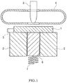
- FIG. 1 is a diagram showing the overall configuration of a magnet cutting device in a first embodiment.
- the magnet cutting device in one embodiment includes a pair of supporting portions 2, a blade 3, a magnet pressing portion 4, a positioning tool 5, a magnet piece supporting tool 6 and a spring 7.
- the pair of supporting portions 2 are spaced apart by a predetermined distance, the pair of supporting portions 2 being configured to support a magnet 1 from bottom side of the magnet.
- the magnet piece supporting tool 6 is arranged between the pair of supporting portions 2 and supports the magnet 1 from below.
- the magnet piece supporting tool 6 is vertically movable by an elastic force of the spring 7.
- FIG. 2 is a diagram enlargedly showing an upper end part of the magnet piece supporting tool 6.
- the magnet piece supporting tool 6 is shaped to be highest in an upper end central part thereof, become lower from the central part toward end parts and include slants connecting the upper end central part and the end parts. Further, in a state where the magnet 1 is placed on the magnet piece supporting tool 6, the upper end central part of the magnet piece supporting tool 6 is arranged to be higher than the upper ends of the pair of supporting portions 2 and both end parts of the upper end of the magnet piece supporting tool 6 are arranged to be lower than the upper ends of the pair of supporting portions 2.
- the shape of the magnet piece supporting tool 6, a spring constant of the spring 7 and the like are so determined that the upper end central part of the magnet piece supporting tool 6 is at a position higher than the pair of supporting portions 2 and the both end parts of the upper end of the magnet piece supporting tool 6 are at positions lower than the pair of supporting portions 2 in the state where the magnet 1 is placed on the magnet piece supporting tool 6.
- the magnet pressing portion 4 functions to press the magnet 1 from above.
- the blade 3 cuts the magnet 1 by pressing the magnet 1 fixed by being vertically sandwiched by the magnet pressing portion 4 and the magnet piece supporting tool 6 downwardly from above.
- a magnet cutting method using the magnet cutting device in the first embodiment is described below.
- Grooves are provided at positions planned to be cut in advance on the magnet 1.
- the magnet 1 is so placed on the supporting portions 2 that the grooves are located on a lower side, and positioned by the known positioning tool 5 (see FIG. 3 ). More specifically, by pushing the magnet 1 in a rightward direction of FIG. 3 by the positioning tool 5, the groove of the magnet 1 is positioned to be located immediately below a lateral center of the blade 3.
- the positioning tool 5 is controlled, for example, using a positioning mechanism such as an LM guide.
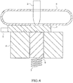
- the magnet pressing portion 4 and the blade 3 are moved downwardly to press the magnet 1 from above by the magnet pressing portion 4 (see FIG. 4 ).
- the blade 3 is pressed downwardly and the magnet 1 is cut by three-point bending by the pair of supporting portions 2 and the blade 3 (see FIG. 5 ). Note that the positioning tool 5 is retracted to a position away from the magnet 1 before the cutting of the magnet 1 so as not to obstruct a movement of the magnet 1 after cutting.
- the spring constant of the spring 7 for vertically moving the magnet piece supporting tool 6 by an elastic force is set at a suitable value so as not to affect cutting by three-point bending.
- the blade 3 and the magnet pressing portion 4 are elevated and the positioning tool 5 is returned to the position before retraction (see FIG. 6 ).
- burrs projections
- the upper end central part of the magnet piece supporting tool 6 is arranged at the position higher than the pair of supporting portions 2 and the both end parts of the upper end of the magnet piece supporting tool 6 are arranged at the positions lower than the upper ends of the pair of supporting portions 2 in the state where the magnet 1 is placed.
- the magnet cutting device in the first embodiment includes the pair of supporting portions 2 spaced apart by the predetermined distance, the pair of supporting portions 2 being configured to support the magnet from bottom side of the magnet, the magnet pressing portion 4 configured to press the magnet supported by the pair of supporting portions 2 from upper side of the magnet and the magnet piece supporting tool 6 vertically movable and arranged between the pair of supporting portions 2 to support the magnet from the bottom side of the magnet. Since the magnet piece supporting tool 6 is arranged between the pair of supporting portions 2, the magnet piece after cutting can be prevented from falling down between the pair of supporting portions.
- the magnet piece supporting tool 6 is so arranged that the upper end central part thereof is higher than the upper ends of the pair of supporting portions 2 and the end parts of the upper end thereof are lower than the upper ends of the pair of supporting portions 2 in the state where the magnet is placed and includes the slants connecting the central part and the end parts, the magnet can be prevented from being caught by the pair of supporting portions 2 when the magnet after cutting is fed.
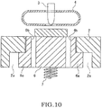
- FIG. 10 is a diagram showing the overall configuration of a magnet cutting device in a second embodiment.
- the magnet cutting device in the second embodiment differs from that in the first embodiment in the structure of a pair of supporting portions 2 and the configuration of a magnet piece supporting tool 6.
- the magnet piece supporting tool 6 includes protruding portions 6a.
- the protruding portions 6a being formed so that a part of an outer and part of the magnet supporting tool 6 protrudes toward the corresponding supporting portion 2 in a state where the magnet supporting tool 6 is arranged between the pair of supporting portions 2.
- These protruding portions 6a protrude outwardly from positions spaced downwardly a predetermined distance from the upper end of the magnet piece supporting tool 6.
- the pair of supporting portions 2 are provided with space portions 2a into which the protruding portions 6a of the magnet piece supporting tool 6 are held or housed.
- At least parts of the upper end of the magnet piece supporting tool 6 are open and air blows out from these opening ends 6b. Since this enables contaminants (crushed powder) to be blown off even if the contaminants are present around the opening ends 6b, a change in the height of the upper end of the magnet piece supporting tool 6 due to the presence of the contaminants can be prevented.
- the opening ends 6b may have a suction function.
- contaminants crushed powder
- the opening ends 6b may have a suction function.
- the magnet piece supporting tool 6 includes the protruding portions 6a protruding toward the pair of supporting portions 2 from the outer end parts of the magnet piece supporting tool 6 in the state where the magnet piece supporting tool 6 arranged between the pair of supporting portions 2, and the pair of supporting portions 2 are provided with the space portions 2a into which the protruding portions 6a of the magnet piece supporting tool 6 are held or housed
- the central part of the upper end of the magnet piece supporting tool 6 is higher than the upper ends of the pair of supporting portions 2 and the end parts of the upper end thereof are lower than the upper ends of the pair of supporting portions 2 in the state where the upper ends of the protruding portions 6a of the magnet piece supporting tool 6 are respectively in contact with the upper ends of the space portions 2a of the pair of supporting portions 2.
- the initial position can be accurately determined.
- the magnet piece supporting tool 6 since the central part of the upper end of the magnet piece supporting tool 6 is higher than the upper ends of the pair of supporting portions 2 and the end parts of the upper end thereof are lower than the upper ends of the pair of supporting portions 2 at the initial position, the magnet can be prevented from being caught by the pair of supporting portions 2 during the feeding of the magnet after cutting as in the magnet cutting device in the first embodiment.
- the magnet piece supporting tool 6 includes the opening ends 6b open in at least parts of the upper end and air blows out from the opening ends 6b, contaminants can be blown off even if the contaminants are present around the open parts. This can prevent a change in the height of the upper end of the magnet piece supporting tool 6 due to the presence of the contaminants.
- the opening ends 6b have the suction function, contaminants can be sucked even if the contaminants are present around the open parts. This can prevent a change in the height of the upper end of the magnet piece supporting tool 6 due to the presence of the contaminants.
- the present invention is not limited to the aforementioned embodiments.
- the pair of supporting portions 2 and the magnet piece supporting tool 6 may have the same configurations as those in the second embodiment.
- opening end(s) may be provided in at least part(s) of the upper end of the magnet piece supporting tool 6 to provide a function of blowing out air from the opening end(s) or a suction function as in the magnet cutting device in the second embodiment.
- the magnet piece supporting tool 6 has only to be shaped to be highest in the upper end central part and become lower from the central part toward the end parts and include the slants connecting the upper end central parts and the end parts, and there is no limitation to the shape shown in FIG. 2 .
- FIG. 11 is a diagram showing an example of another shape of the magnet piece supporting tool 6.
- the magnet piece supporting tool 6 may also be shaped as shown in FIG. 11 .
Landscapes
- Engineering & Computer Science (AREA)
- Power Engineering (AREA)
- Mechanical Engineering (AREA)
- Life Sciences & Earth Sciences (AREA)
- Forests & Forestry (AREA)
- Manufacturing & Machinery (AREA)
- Mining & Mineral Resources (AREA)
- Permanent Field Magnets Of Synchronous Machinery (AREA)
- Table Equipment (AREA)
- Filtering Of Dispersed Particles In Gases (AREA)
Abstract
Description
- This invention relates to a device for cutting a magnet.
- Conventionally, there is known a technology using a long plate-like magnet formed by dividing a long magnet into a plurality of magnet pieces and integrating the plurality of divided magnet pieces as a magnet to be inserted into a magnet insertion hole of a rotor core of a motor to reduce an eddy current possibly generated in the magnet (see
JP2009-142081A JP2009-142081A - Here, in the cutting method of
JP2009-142081A - The present invention aims to prevent a magnet piece after cutting from falling down between a pair of supporting portions and prevent a magnet from being caught by the pair of supporting portions at the time of feeding the magnet.
- The magnet cutting device in embodiment of the present invention includes a pair of supporting portions spaced apart by a predetermined distance, the pair of supporting portions being configured to support the magnet from bottom side of the magnet, a pressing portion configured to press the magnet supported by the pair of supporting portions from a upper side of the magnet, and a magnet supporting tool arranged between the pair of supporting portions to support the magnet from the bottom side of the magnet, the magnet supporting tool being configured to be vertically movable. A surface of the magnet supporting tool to be held in contact with the magnet is shaped such that a central part of an upper end of the magnet supporting tool is higher than the upper ends of the pair of supporting portions and an end part of the upper end of the magnet supporting tool is lower than the upper ends of the pair of supporting portions in a state where the magnet is placed on the surface, the upper end of the magnet supporting tool having a slope connecting the central part and the end part.
- Embodiments and advantages of the present invention will be described in detail below with reference to the attached figures.
-
-
FIG. 1 is a diagram showing the overall configuration of a magnet cutting device in a first embodiment, -
FIG. 2 is a diagram enlargedly showing an upper end part of a magnet piece supporting tool, -
FIG. 3 is a diagram showing a method for positioning a magnet for cutting, -
FIG. 4 is a diagram showing a state where the magnet is pressed from above by a magnet pressing portion, -
FIG. 5 is a diagram showing a state where the magnet is cut by pressing a blade downwardly, -
FIG. 6 is a diagram showing a state where the blade and the magnet pressing portion are elevated after the cutting of the magnet, -
FIG. 7 is a diagram showing a method for positioning such that the next groove of the magnet is located immediately below a lateral center of the blade, -
FIG. 8 is a diagram showing the method for positioning such that the next groove of the magnet is located immediately below the lateral center of the blade, -
FIG. 9 is a diagram showing an effect of the magnet cutting device in the first embodiment, -
FIG. 10 is a diagram showing the overall configuration of a magnet cutting device in a second embodiment, and -
FIG. 11 is a diagram showing an example of another shape of the magnet piece supporting tool. -
FIG. 1 is a diagram showing the overall configuration of a magnet cutting device in a first embodiment. The magnet cutting device in one embodiment includes a pair of supportingportions 2, ablade 3, amagnet pressing portion 4, apositioning tool 5, a magnetpiece supporting tool 6 and aspring 7. - The pair of supporting
portions 2 are spaced apart by a predetermined distance, the pair of supportingportions 2 being configured to support amagnet 1 from bottom side of the magnet. As shown inFIG. 1 , the magnetpiece supporting tool 6 is arranged between the pair of supportingportions 2 and supports themagnet 1 from below. The magnetpiece supporting tool 6 is vertically movable by an elastic force of thespring 7. -
FIG. 2 is a diagram enlargedly showing an upper end part of the magnetpiece supporting tool 6. As shown inFIG. 2 , the magnetpiece supporting tool 6 is shaped to be highest in an upper end central part thereof, become lower from the central part toward end parts and include slants connecting the upper end central part and the end parts. Further, in a state where themagnet 1 is placed on the magnetpiece supporting tool 6, the upper end central part of the magnetpiece supporting tool 6 is arranged to be higher than the upper ends of the pair of supportingportions 2 and both end parts of the upper end of the magnetpiece supporting tool 6 are arranged to be lower than the upper ends of the pair of supportingportions 2. Specifically, the shape of the magnetpiece supporting tool 6, a spring constant of thespring 7 and the like are so determined that the upper end central part of the magnetpiece supporting tool 6 is at a position higher than the pair of supportingportions 2 and the both end parts of the upper end of the magnetpiece supporting tool 6 are at positions lower than the pair of supportingportions 2 in the state where themagnet 1 is placed on the magnetpiece supporting tool 6. - The
magnet pressing portion 4 functions to press themagnet 1 from above. Theblade 3 cuts themagnet 1 by pressing themagnet 1 fixed by being vertically sandwiched by themagnet pressing portion 4 and the magnetpiece supporting tool 6 downwardly from above. - A magnet cutting method using the magnet cutting device in the first embodiment is described below.
- Grooves are provided at positions planned to be cut in advance on the
magnet 1. Themagnet 1 is so placed on the supportingportions 2 that the grooves are located on a lower side, and positioned by the known positioning tool 5 (seeFIG. 3 ). More specifically, by pushing themagnet 1 in a rightward direction ofFIG. 3 by thepositioning tool 5, the groove of themagnet 1 is positioned to be located immediately below a lateral center of theblade 3. Thepositioning tool 5 is controlled, for example, using a positioning mechanism such as an LM guide. - Subsequently, the
magnet pressing portion 4 and theblade 3 are moved downwardly to press themagnet 1 from above by the magnet pressing portion 4 (seeFIG. 4 ). - Subsequently, the
blade 3 is pressed downwardly and themagnet 1 is cut by three-point bending by the pair of supportingportions 2 and the blade 3 (seeFIG. 5 ). Note that thepositioning tool 5 is retracted to a position away from themagnet 1 before the cutting of themagnet 1 so as not to obstruct a movement of themagnet 1 after cutting. - Since the
spring 7 is compressed via the magnetpiece supporting tool 6 held in contact with themagnet 1 by a force for pressing theblade 3 downwardly, the magnetpiece supporting tool 6 is pressed downwardly. The spring constant of thespring 7 for vertically moving the magnetpiece supporting tool 6 by an elastic force is set at a suitable value so as not to affect cutting by three-point bending. - When the
magnet 1 is cut, theblade 3 and themagnet pressing portion 4 are elevated and thepositioning tool 5 is returned to the position before retraction (seeFIG. 6 ). - Thereafter, by pushing the
magnet 1 in a rightward direction ofFIG. 7 by thepositioning tool 5, the next groove of themagnet 1 is positioned to be located immediately below the lateral center of theblade 3. This causes acut magnet piece 1a to be also pushed and carried onto the supportingportion 2 located on the right side ofFIG. 7 (seeFIGS. 7 and8 ). It should be noted that the spring constant and an expansion and contraction amount of thespring 7 are so selected that the magnetpiece supporting tool 6 does not sink during the next positioning after the cutting of themagnet 1. - When the
magnet 1 is cut, burrs (projections) may be generated on and near a cut surface. In the magnet cutting device in the first embodiment, as described above, the upper end central part of the magnetpiece supporting tool 6 is arranged at the position higher than the pair of supportingportions 2 and the both end parts of the upper end of the magnetpiece supporting tool 6 are arranged at the positions lower than the upper ends of the pair of supportingportions 2 in the state where themagnet 1 is placed. Thus, even if burrs are present on themagnet 1 during the next positioning after magnet cutting, the magnet pushed by thepositioning tool 5 is not caught by the supportingportions 2. Specifically, since the upper end central part of the magnetpiece supporting tool 6 is at the position higher than the pair of supportingportions 2, a front end part of themagnet 1 pushed by thepositioning tool 5 in a moving direction is at a position higher than the supportingportions 2 and aburr 10 of themagnet 1 is not caught by the supportingportion 2 as shown inFIG. 9 . - As described above, the magnet cutting device in the first embodiment includes the pair of supporting
portions 2 spaced apart by the predetermined distance, the pair of supportingportions 2 being configured to support the magnet from bottom side of the magnet, themagnet pressing portion 4 configured to press the magnet supported by the pair of supportingportions 2 from upper side of the magnet and the magnetpiece supporting tool 6 vertically movable and arranged between the pair of supportingportions 2 to support the magnet from the bottom side of the magnet. Since the magnetpiece supporting tool 6 is arranged between the pair of supportingportions 2, the magnet piece after cutting can be prevented from falling down between the pair of supporting portions. Further, since the magnetpiece supporting tool 6 is so arranged that the upper end central part thereof is higher than the upper ends of the pair of supportingportions 2 and the end parts of the upper end thereof are lower than the upper ends of the pair of supportingportions 2 in the state where the magnet is placed and includes the slants connecting the central part and the end parts, the magnet can be prevented from being caught by the pair of supportingportions 2 when the magnet after cutting is fed. - It should be noted that if the
magnet 1 is lifted and fed during the next positioning after magnet cutting, themagnet 1 is not caught by the supportingportions 2 even if burrs are present on themagnet 1. However, if a configuration for lifting and feeding themagnet 1 is adopted, equipment cost increases and positioning takes time. However, according to the magnet cutting device in this embodiment, such problems do not occur. -
FIG. 10 is a diagram showing the overall configuration of a magnet cutting device in a second embodiment. The magnet cutting device in the second embodiment differs from that in the first embodiment in the structure of a pair of supportingportions 2 and the configuration of a magnetpiece supporting tool 6. - The magnet
piece supporting tool 6 includes protrudingportions 6a. the protrudingportions 6a being formed so that a part of an outer and part of themagnet supporting tool 6 protrudes toward the corresponding supportingportion 2 in a state where themagnet supporting tool 6 is arranged between the pair of supportingportions 2. These protrudingportions 6a protrude outwardly from positions spaced downwardly a predetermined distance from the upper end of the magnetpiece supporting tool 6. Further, the pair of supportingportions 2 are provided withspace portions 2a into which the protrudingportions 6a of the magnetpiece supporting tool 6 are held or housed. - In a state where the upper ends of the protruding
portions 6a of the magnetpiece supporting tool 6 are in contact with the upper ends of thespace portions 2a of the supporting portions 2 (state shown inFIG. 10 ), a central part of the upper end of the magnetpiece supporting tool 6 is higher than the upper ends of the pair of supportingportions 2 and end parts of the upper end thereof are lower than the upper ends of the pair of supportingportions 2. This enables the upper end of the magnetpiece supporting tool 6 to be more accurately positioned when the magnetpiece supporting tool 6 moved downwardly at the time of cutting themagnet 1 is elevated after the cutting of the magnet. - Further, at least parts of the upper end of the magnet
piece supporting tool 6 are open and air blows out from these opening ends 6b. Since this enables contaminants (crushed powder) to be blown off even if the contaminants are present around the opening ends 6b, a change in the height of the upper end of the magnetpiece supporting tool 6 due to the presence of the contaminants can be prevented. - Further, the opening ends 6b may have a suction function. By providing the opening ends 6b with the suction function, contaminants (crushed powder) can be sucked even if the contaminants are present around the opening ends 6b. Thus, a change in the height of the upper end of the magnet
piece supporting tool 6 due to the presence of the contaminants can be prevented. - As described above, according to the magnet cutting device in the second embodiment, the magnet
piece supporting tool 6 includes the protrudingportions 6a protruding toward the pair of supportingportions 2 from the outer end parts of the magnetpiece supporting tool 6 in the state where the magnetpiece supporting tool 6 arranged between the pair of supportingportions 2, and the pair of supportingportions 2 are provided with thespace portions 2a into which the protrudingportions 6a of the magnetpiece supporting tool 6 are held or housed The central part of the upper end of the magnetpiece supporting tool 6 is higher than the upper ends of the pair of supportingportions 2 and the end parts of the upper end thereof are lower than the upper ends of the pair of supportingportions 2 in the state where the upper ends of the protrudingportions 6a of the magnetpiece supporting tool 6 are respectively in contact with the upper ends of thespace portions 2a of the pair of supportingportions 2. This enables the upper end of the magnetpiece supporting tool 6 to be more accurately positioned when the magnetpiece supporting tool 6 moved downwardly at the time of cutting themagnet 1 is elevated after the cutting of the magnet. Specifically, the magnetpiece supporting tool 6 is elevated after the cutting of the magnet. Since a position where the upper ends of the protrudingportions 6a of the magnetpiece supporting tool 6 are in contact with the pair of supportingportions 2 is an initial position, the initial position can be accurately determined. Further, since the central part of the upper end of the magnetpiece supporting tool 6 is higher than the upper ends of the pair of supportingportions 2 and the end parts of the upper end thereof are lower than the upper ends of the pair of supportingportions 2 at the initial position, the magnet can be prevented from being caught by the pair of supportingportions 2 during the feeding of the magnet after cutting as in the magnet cutting device in the first embodiment. - Further, since the magnet
piece supporting tool 6 includes the opening ends 6b open in at least parts of the upper end and air blows out from the opening ends 6b, contaminants can be blown off even if the contaminants are present around the open parts. This can prevent a change in the height of the upper end of the magnetpiece supporting tool 6 due to the presence of the contaminants. - Further, if the opening ends 6b have the suction function, contaminants can be sucked even if the contaminants are present around the open parts. This can prevent a change in the height of the upper end of the magnet
piece supporting tool 6 due to the presence of the contaminants. - The present invention is not limited to the aforementioned embodiments. For example, in the magnet cutting device in the first embodiment, the pair of supporting
portions 2 and the magnetpiece supporting tool 6 may have the same configurations as those in the second embodiment. Further, in the magnet cutting device in the first embodiment, opening end(s) may be provided in at least part(s) of the upper end of the magnetpiece supporting tool 6 to provide a function of blowing out air from the opening end(s) or a suction function as in the magnet cutting device in the second embodiment. - The magnet
piece supporting tool 6 has only to be shaped to be highest in the upper end central part and become lower from the central part toward the end parts and include the slants connecting the upper end central parts and the end parts, and there is no limitation to the shape shown inFIG. 2 .FIG. 11 is a diagram showing an example of another shape of the magnetpiece supporting tool 6. The magnetpiece supporting tool 6 may also be shaped as shown inFIG. 11 . - This application claims priority based on
Japanese Patent Application No 2013-124806 filed with the Japan Patent Office on June 13, 2013
Claims (4)
- A magnet cutting device, comprising:a pair of supporting portions spaced apart by a predetermined distance, the pair of supporting portions being configured to support a magnet from bottom side of the magnet;a pressing portion configured to press the magnet supported by the pair of supporting portions from a upper side of the magnet; anda magnet supporting tool arranged between the pair of supporting portions to support the magnet from the bottom side of the magnet, the magnet supporting tool being configured to be vertically movable;wherein a surface of the magnet supporting tool to be held in contact with the magnet is shaped such that a central part of an upper end of the magnet supporting tool is higher than the upper ends of the pair of supporting portions and an end part of the upper end of the magnet supporting tool is lower than the upper ends of the pair of supporting portions in a state where the magnet is placed on the surface, the upper end of the magnet supporting tool having a slope connecting the central part and the end part.
- The magnet cutting device according to claim 1, wherein:the magnet supporting tool includes protruding portions, each of the protruding portions being formed so that a part of an outer and part of the magnet supporting tool protrudes toward the corresponding supporting portion in a state where the magnet supporting tool is arranged between the pair of supporting portions;each of the supporting portions includes a space portion, the protruding portions of the magnet supporting tool being respectively to be held in the space portions of the supporting portions; andthe central part of the upper end of the magnet supporting tool is higher than the upper ends of the pair of supporting portions and the end parts of the upper end of the magnet supporting tool are lower than the upper ends of the pair of supporting portions in a state where the upper ends of the protruding portions of the magnet supporting tool are respectively in contact with upper ends of the space portions of the pair of supporting portions.
- The magnet cutting device according to claim 1 or 2, wherein:the magnet supporting tool includes an opening end so that at least a part of the upper end is opened and air blows out from the opening end.
- The magnet cutting device according to any one of claims 1 to 3, wherein:the magnet supporting tool includes an opening end so that at least a part of the upper end is opened and the opening end has a suction function.
Applications Claiming Priority (2)
| Application Number | Priority Date | Filing Date | Title |
|---|---|---|---|
| JP2013124806 | 2013-06-13 | ||
| PCT/JP2014/061754 WO2014199734A1 (en) | 2013-06-13 | 2014-04-25 | Magnet fracturing device |
Publications (3)
| Publication Number | Publication Date |
|---|---|
| EP3010123A1 true EP3010123A1 (en) | 2016-04-20 |
| EP3010123A4 EP3010123A4 (en) | 2016-06-08 |
| EP3010123B1 EP3010123B1 (en) | 2017-03-29 |
Family
ID=52022036
Family Applications (1)
| Application Number | Title | Priority Date | Filing Date |
|---|---|---|---|
| EP14810548.9A Active EP3010123B1 (en) | 2013-06-13 | 2014-04-25 | Magnet fracturing device |
Country Status (5)
| Country | Link |
|---|---|
| US (1) | US10668641B2 (en) |
| EP (1) | EP3010123B1 (en) |
| JP (1) | JP5999263B2 (en) |
| CN (1) | CN105264754B (en) |
| WO (1) | WO2014199734A1 (en) |
Families Citing this family (4)
| Publication number | Priority date | Publication date | Assignee | Title |
|---|---|---|---|---|
| US10773420B2 (en) * | 2011-11-10 | 2020-09-15 | LatticeGear, LLC | Device and method for cleaving a substrate |
| US10065340B2 (en) * | 2011-11-10 | 2018-09-04 | LatticeGear, LLC | Device and method for cleaving |
| FR3007681B1 (en) * | 2013-07-01 | 2015-07-17 | Oberthur Technologies | MANUFACTURE OF A PLATE OF LARGE THICKNESS COMPRISING A DETACHABLE CARD OF SMALL THICKNESS |
| CN113315324B (en) * | 2021-07-07 | 2022-04-05 | 徐州给力磁业有限公司 | Magnetic steel production equipment for motor |
Family Cites Families (17)
| Publication number | Priority date | Publication date | Assignee | Title |
|---|---|---|---|---|
| US1874786A (en) * | 1930-09-29 | 1932-08-30 | Mitchell Peter | Ring fracturing machine |
| SE310768B (en) * | 1962-08-31 | 1969-05-12 | Lkb Produkter Ab | |
| US4730763A (en) * | 1984-07-12 | 1988-03-15 | Trw Inc. | Means and method for scoring and severing an optical fiber |
| AT391858B (en) * | 1988-04-25 | 1990-12-10 | Lisec Peter | DEVICE FOR BREAKING SINGLE-SIDED GLASS PANELS |
| AT399865B (en) * | 1990-05-15 | 1995-08-25 | Lisec Peter | METHOD AND DEVICE FOR BREAKING GLASS PANES |
| JP3326384B2 (en) * | 1998-03-12 | 2002-09-24 | 古河電気工業株式会社 | Method and apparatus for cleaving semiconductor wafer |
| WO2004082911A1 (en) * | 2003-03-17 | 2004-09-30 | Baumann Gmbh | Breaking device for separating ceramic printed circuit boards |
| ATE517849T1 (en) * | 2003-11-06 | 2011-08-15 | Peter Lisec | METHOD AND DEVICE FOR BREAKING SCRATCHED GLASS PANELS |
| US20080110952A1 (en) * | 2006-11-15 | 2008-05-15 | Marvin William Kemmerer | Sheet separation through fluid impact |
| JP4497198B2 (en) | 2007-12-06 | 2010-07-07 | トヨタ自動車株式会社 | Permanent magnet and method for manufacturing the same, and rotor and IPM motor |
| WO2011004490A1 (en) * | 2009-07-10 | 2011-01-13 | トヨタ自動車株式会社 | Device for cleaving magnet and method for cleaving magnet |
| JP5614096B2 (en) * | 2010-05-19 | 2014-10-29 | 日産自動車株式会社 | Permanent magnet embedded in rotor core of rotating electrical machine and method for manufacturing the same |
| KR101504441B1 (en) * | 2010-06-17 | 2015-03-19 | 닛산 지도우샤 가부시키가이샤 | Device and method for manufacturing permanent magnets provided to dynamo-electric machine |
| EP2738922B1 (en) * | 2011-07-27 | 2020-03-25 | Nissan Motor Co., Ltd | Device for producing field-pole magnet and method for producing same |
| JP6393019B2 (en) * | 2011-09-26 | 2018-09-19 | 日産自動車株式会社 | Field pole magnet body manufacturing apparatus and method |
| JP5929310B2 (en) * | 2012-02-28 | 2016-06-01 | 日産自動車株式会社 | Manufacturing method of magnet piece constituting magnetic body for field pole |
| EP2869440B1 (en) * | 2012-07-02 | 2017-02-01 | Nissan Motor Co., Ltd. | Apparatus and method for manufacturing magnet segments constituting field pole magnetic body |
-
2014
- 2014-04-25 US US14/896,979 patent/US10668641B2/en active Active
- 2014-04-25 EP EP14810548.9A patent/EP3010123B1/en active Active
- 2014-04-25 WO PCT/JP2014/061754 patent/WO2014199734A1/en not_active Ceased
- 2014-04-25 JP JP2015522633A patent/JP5999263B2/en active Active
- 2014-04-25 CN CN201480032743.5A patent/CN105264754B/en active Active
Also Published As
| Publication number | Publication date |
|---|---|
| JP5999263B2 (en) | 2016-09-28 |
| CN105264754B (en) | 2017-10-27 |
| JPWO2014199734A1 (en) | 2017-02-23 |
| EP3010123A4 (en) | 2016-06-08 |
| WO2014199734A1 (en) | 2014-12-18 |
| US20160136835A1 (en) | 2016-05-19 |
| CN105264754A (en) | 2016-01-20 |
| US10668641B2 (en) | 2020-06-02 |
| EP3010123B1 (en) | 2017-03-29 |
Similar Documents
| Publication | Publication Date | Title |
|---|---|---|
| EP3010123B1 (en) | Magnet fracturing device | |
| KR101932305B1 (en) | Press mold apparatus minimized failure probability of ejecting blank and scrap | |
| EP2573916A1 (en) | Permanent magnet provided to dynamo-electric machine, and method for manufacturing same | |
| CN210025562U (en) | Card cutting machine | |
| CN110364967B (en) | Cutting tool | |
| KR20130035710A (en) | Relay punching mold and method of punching using relay punching mold | |
| CN105580245B (en) | Cut-off method and chopping up apparatus that the field pole configured to being formed in electric rotating machine is manufactured with the magnetite pieces of magnetite body | |
| JP2012210643A (en) | Forming device | |
| US9597813B2 (en) | Method and device for producing a stripping tool | |
| CN101958500B (en) | Method for processing plug for electric socket and special mould | |
| CN207563520U (en) | Singles' copper belt machine | |
| JP4868460B2 (en) | Mold for processing base plate, method for manufacturing processed plate, and method for manufacturing product plate | |
| CN105081061A (en) | Punching die for stainless steel tube | |
| KR101103843B1 (en) | Metal strip punching device with change punch | |
| CN212760631U (en) | Die-cut mould of die casting | |
| CN213125017U (en) | Automobile wire harness terminal crimping blade and crimping die | |
| CN203171716U (en) | Head cutting and resetting structure of automobile decoration strip class products | |
| JP5005299B2 (en) | Press machine | |
| CN209935659U (en) | Small ring forging piece punching sheath die | |
| CN210475178U (en) | Motor casing perforating device | |
| CN103521650A (en) | PIN breaking machine | |
| JP2025095984A (en) | Press processing equipment | |
| KR101368389B1 (en) | Punch die aid for paper box | |
| JP4439563B2 (en) | Mold for shaving, manufacturing method of processed plate, and manufacturing method of product plate | |
| JPH0357524A (en) | Blanking device |
Legal Events
| Date | Code | Title | Description |
|---|---|---|---|
| PUAI | Public reference made under article 153(3) epc to a published international application that has entered the european phase |
Free format text: ORIGINAL CODE: 0009012 |
|
| 17P | Request for examination filed |
Effective date: 20151203 |
|
| AK | Designated contracting states |
Kind code of ref document: A1 Designated state(s): AL AT BE BG CH CY CZ DE DK EE ES FI FR GB GR HR HU IE IS IT LI LT LU LV MC MK MT NL NO PL PT RO RS SE SI SK SM TR |
|
| AX | Request for extension of the european patent |
Extension state: BA ME |
|
| A4 | Supplementary search report drawn up and despatched |
Effective date: 20160509 |
|
| RIC1 | Information provided on ipc code assigned before grant |
Ipc: H01F 41/02 20060101ALI20160502BHEP Ipc: B26F 3/00 20060101ALI20160502BHEP Ipc: B28D 1/28 20060101ALI20160502BHEP Ipc: H02K 15/03 20060101AFI20160502BHEP Ipc: B26F 3/02 20060101ALI20160502BHEP |
|
| DAX | Request for extension of the european patent (deleted) | ||
| RIC1 | Information provided on ipc code assigned before grant |
Ipc: H02K 15/03 20060101AFI20161027BHEP Ipc: B26F 3/00 20060101ALI20161027BHEP Ipc: B28D 1/28 20060101ALI20161027BHEP Ipc: H01F 41/02 20060101ALI20161027BHEP Ipc: B26F 3/02 20060101ALI20161027BHEP |
|
| GRAP | Despatch of communication of intention to grant a patent |
Free format text: ORIGINAL CODE: EPIDOSNIGR1 |
|
| INTG | Intention to grant announced |
Effective date: 20161202 |
|
| GRAS | Grant fee paid |
Free format text: ORIGINAL CODE: EPIDOSNIGR3 |
|
| GRAA | (expected) grant |
Free format text: ORIGINAL CODE: 0009210 |
|
| AK | Designated contracting states |
Kind code of ref document: B1 Designated state(s): AL AT BE BG CH CY CZ DE DK EE ES FI FR GB GR HR HU IE IS IT LI LT LU LV MC MK MT NL NO PL PT RO RS SE SI SK SM TR |
|
| RAP1 | Party data changed (applicant data changed or rights of an application transferred) |
Owner name: NISSAN MOTOR CO., LTD. |
|
| REG | Reference to a national code |
Ref country code: GB Ref legal event code: FG4D |
|
| RIN1 | Information on inventor provided before grant (corrected) |
Inventor name: NISHIMURA, KIMIO Inventor name: MATSUSHITA, YASUSHI Inventor name: SEKIKAWA, TAKASHI Inventor name: OHSHIMA, TAKUMI Inventor name: HORI, AKIHISA Inventor name: KISHI, MICHITO Inventor name: HASEGAWA, KIYOSHI |
|
| REG | Reference to a national code |
Ref country code: CH Ref legal event code: EP |
|
| REG | Reference to a national code |
Ref country code: AT Ref legal event code: REF Ref document number: 880604 Country of ref document: AT Kind code of ref document: T Effective date: 20170415 |
|
| REG | Reference to a national code |
Ref country code: IE Ref legal event code: FG4D |
|
| REG | Reference to a national code |
Ref country code: FR Ref legal event code: PLFP Year of fee payment: 4 |
|
| REG | Reference to a national code |
Ref country code: DE Ref legal event code: R096 Ref document number: 602014008176 Country of ref document: DE |
|
| PG25 | Lapsed in a contracting state [announced via postgrant information from national office to epo] |
Ref country code: HR Free format text: LAPSE BECAUSE OF FAILURE TO SUBMIT A TRANSLATION OF THE DESCRIPTION OR TO PAY THE FEE WITHIN THE PRESCRIBED TIME-LIMIT Effective date: 20170329 Ref country code: GR Free format text: LAPSE BECAUSE OF FAILURE TO SUBMIT A TRANSLATION OF THE DESCRIPTION OR TO PAY THE FEE WITHIN THE PRESCRIBED TIME-LIMIT Effective date: 20170630 Ref country code: LT Free format text: LAPSE BECAUSE OF FAILURE TO SUBMIT A TRANSLATION OF THE DESCRIPTION OR TO PAY THE FEE WITHIN THE PRESCRIBED TIME-LIMIT Effective date: 20170329 Ref country code: NO Free format text: LAPSE BECAUSE OF FAILURE TO SUBMIT A TRANSLATION OF THE DESCRIPTION OR TO PAY THE FEE WITHIN THE PRESCRIBED TIME-LIMIT Effective date: 20170629 Ref country code: FI Free format text: LAPSE BECAUSE OF FAILURE TO SUBMIT A TRANSLATION OF THE DESCRIPTION OR TO PAY THE FEE WITHIN THE PRESCRIBED TIME-LIMIT Effective date: 20170329 |
|
| REG | Reference to a national code |
Ref country code: NL Ref legal event code: MP Effective date: 20170329 |
|
| REG | Reference to a national code |
Ref country code: AT Ref legal event code: MK05 Ref document number: 880604 Country of ref document: AT Kind code of ref document: T Effective date: 20170329 |
|
| PG25 | Lapsed in a contracting state [announced via postgrant information from national office to epo] |
Ref country code: BG Free format text: LAPSE BECAUSE OF FAILURE TO SUBMIT A TRANSLATION OF THE DESCRIPTION OR TO PAY THE FEE WITHIN THE PRESCRIBED TIME-LIMIT Effective date: 20170629 Ref country code: RS Free format text: LAPSE BECAUSE OF FAILURE TO SUBMIT A TRANSLATION OF THE DESCRIPTION OR TO PAY THE FEE WITHIN THE PRESCRIBED TIME-LIMIT Effective date: 20170329 Ref country code: LV Free format text: LAPSE BECAUSE OF FAILURE TO SUBMIT A TRANSLATION OF THE DESCRIPTION OR TO PAY THE FEE WITHIN THE PRESCRIBED TIME-LIMIT Effective date: 20170329 Ref country code: SE Free format text: LAPSE BECAUSE OF FAILURE TO SUBMIT A TRANSLATION OF THE DESCRIPTION OR TO PAY THE FEE WITHIN THE PRESCRIBED TIME-LIMIT Effective date: 20170329 |
|
| PG25 | Lapsed in a contracting state [announced via postgrant information from national office to epo] |
Ref country code: NL Free format text: LAPSE BECAUSE OF FAILURE TO SUBMIT A TRANSLATION OF THE DESCRIPTION OR TO PAY THE FEE WITHIN THE PRESCRIBED TIME-LIMIT Effective date: 20170329 |
|
| PG25 | Lapsed in a contracting state [announced via postgrant information from national office to epo] |
Ref country code: EE Free format text: LAPSE BECAUSE OF FAILURE TO SUBMIT A TRANSLATION OF THE DESCRIPTION OR TO PAY THE FEE WITHIN THE PRESCRIBED TIME-LIMIT Effective date: 20170329 Ref country code: SK Free format text: LAPSE BECAUSE OF FAILURE TO SUBMIT A TRANSLATION OF THE DESCRIPTION OR TO PAY THE FEE WITHIN THE PRESCRIBED TIME-LIMIT Effective date: 20170329 Ref country code: ES Free format text: LAPSE BECAUSE OF FAILURE TO SUBMIT A TRANSLATION OF THE DESCRIPTION OR TO PAY THE FEE WITHIN THE PRESCRIBED TIME-LIMIT Effective date: 20170329 Ref country code: IT Free format text: LAPSE BECAUSE OF FAILURE TO SUBMIT A TRANSLATION OF THE DESCRIPTION OR TO PAY THE FEE WITHIN THE PRESCRIBED TIME-LIMIT Effective date: 20170329 Ref country code: CZ Free format text: LAPSE BECAUSE OF FAILURE TO SUBMIT A TRANSLATION OF THE DESCRIPTION OR TO PAY THE FEE WITHIN THE PRESCRIBED TIME-LIMIT Effective date: 20170329 Ref country code: AT Free format text: LAPSE BECAUSE OF FAILURE TO SUBMIT A TRANSLATION OF THE DESCRIPTION OR TO PAY THE FEE WITHIN THE PRESCRIBED TIME-LIMIT Effective date: 20170329 Ref country code: RO Free format text: LAPSE BECAUSE OF FAILURE TO SUBMIT A TRANSLATION OF THE DESCRIPTION OR TO PAY THE FEE WITHIN THE PRESCRIBED TIME-LIMIT Effective date: 20170329 |
|
| PG25 | Lapsed in a contracting state [announced via postgrant information from national office to epo] |
Ref country code: IS Free format text: LAPSE BECAUSE OF FAILURE TO SUBMIT A TRANSLATION OF THE DESCRIPTION OR TO PAY THE FEE WITHIN THE PRESCRIBED TIME-LIMIT Effective date: 20170729 Ref country code: PL Free format text: LAPSE BECAUSE OF FAILURE TO SUBMIT A TRANSLATION OF THE DESCRIPTION OR TO PAY THE FEE WITHIN THE PRESCRIBED TIME-LIMIT Effective date: 20170329 Ref country code: SM Free format text: LAPSE BECAUSE OF FAILURE TO SUBMIT A TRANSLATION OF THE DESCRIPTION OR TO PAY THE FEE WITHIN THE PRESCRIBED TIME-LIMIT Effective date: 20170329 |
|
| REG | Reference to a national code |
Ref country code: CH Ref legal event code: PL |
|
| REG | Reference to a national code |
Ref country code: DE Ref legal event code: R097 Ref document number: 602014008176 Country of ref document: DE |
|
| REG | Reference to a national code |
Ref country code: IE Ref legal event code: MM4A |
|
| PG25 | Lapsed in a contracting state [announced via postgrant information from national office to epo] |
Ref country code: DK Free format text: LAPSE BECAUSE OF FAILURE TO SUBMIT A TRANSLATION OF THE DESCRIPTION OR TO PAY THE FEE WITHIN THE PRESCRIBED TIME-LIMIT Effective date: 20170329 Ref country code: MC Free format text: LAPSE BECAUSE OF FAILURE TO SUBMIT A TRANSLATION OF THE DESCRIPTION OR TO PAY THE FEE WITHIN THE PRESCRIBED TIME-LIMIT Effective date: 20170329 |
|
| PLBE | No opposition filed within time limit |
Free format text: ORIGINAL CODE: 0009261 |
|
| STAA | Information on the status of an ep patent application or granted ep patent |
Free format text: STATUS: NO OPPOSITION FILED WITHIN TIME LIMIT |
|
| PG25 | Lapsed in a contracting state [announced via postgrant information from national office to epo] |
Ref country code: LU Free format text: LAPSE BECAUSE OF NON-PAYMENT OF DUE FEES Effective date: 20170425 Ref country code: CH Free format text: LAPSE BECAUSE OF NON-PAYMENT OF DUE FEES Effective date: 20170430 Ref country code: LI Free format text: LAPSE BECAUSE OF NON-PAYMENT OF DUE FEES Effective date: 20170430 |
|
| 26N | No opposition filed |
Effective date: 20180103 |
|
| REG | Reference to a national code |
Ref country code: FR Ref legal event code: PLFP Year of fee payment: 5 |
|
| REG | Reference to a national code |
Ref country code: BE Ref legal event code: MM Effective date: 20170430 |
|
| PG25 | Lapsed in a contracting state [announced via postgrant information from national office to epo] |
Ref country code: IE Free format text: LAPSE BECAUSE OF NON-PAYMENT OF DUE FEES Effective date: 20170425 |
|
| PG25 | Lapsed in a contracting state [announced via postgrant information from national office to epo] |
Ref country code: BE Free format text: LAPSE BECAUSE OF NON-PAYMENT OF DUE FEES Effective date: 20170430 Ref country code: SI Free format text: LAPSE BECAUSE OF FAILURE TO SUBMIT A TRANSLATION OF THE DESCRIPTION OR TO PAY THE FEE WITHIN THE PRESCRIBED TIME-LIMIT Effective date: 20170329 |
|
| PG25 | Lapsed in a contracting state [announced via postgrant information from national office to epo] |
Ref country code: MT Free format text: LAPSE BECAUSE OF NON-PAYMENT OF DUE FEES Effective date: 20170425 |
|
| PG25 | Lapsed in a contracting state [announced via postgrant information from national office to epo] |
Ref country code: HU Free format text: LAPSE BECAUSE OF FAILURE TO SUBMIT A TRANSLATION OF THE DESCRIPTION OR TO PAY THE FEE WITHIN THE PRESCRIBED TIME-LIMIT; INVALID AB INITIO Effective date: 20140425 |
|
| PG25 | Lapsed in a contracting state [announced via postgrant information from national office to epo] |
Ref country code: CY Free format text: LAPSE BECAUSE OF FAILURE TO SUBMIT A TRANSLATION OF THE DESCRIPTION OR TO PAY THE FEE WITHIN THE PRESCRIBED TIME-LIMIT Effective date: 20170329 |
|
| PG25 | Lapsed in a contracting state [announced via postgrant information from national office to epo] |
Ref country code: MK Free format text: LAPSE BECAUSE OF FAILURE TO SUBMIT A TRANSLATION OF THE DESCRIPTION OR TO PAY THE FEE WITHIN THE PRESCRIBED TIME-LIMIT Effective date: 20170329 |
|
| PG25 | Lapsed in a contracting state [announced via postgrant information from national office to epo] |
Ref country code: TR Free format text: LAPSE BECAUSE OF FAILURE TO SUBMIT A TRANSLATION OF THE DESCRIPTION OR TO PAY THE FEE WITHIN THE PRESCRIBED TIME-LIMIT Effective date: 20170329 |
|
| PG25 | Lapsed in a contracting state [announced via postgrant information from national office to epo] |
Ref country code: PT Free format text: LAPSE BECAUSE OF FAILURE TO SUBMIT A TRANSLATION OF THE DESCRIPTION OR TO PAY THE FEE WITHIN THE PRESCRIBED TIME-LIMIT Effective date: 20170329 |
|
| PG25 | Lapsed in a contracting state [announced via postgrant information from national office to epo] |
Ref country code: AL Free format text: LAPSE BECAUSE OF FAILURE TO SUBMIT A TRANSLATION OF THE DESCRIPTION OR TO PAY THE FEE WITHIN THE PRESCRIBED TIME-LIMIT Effective date: 20170329 |
|
| PGFP | Annual fee paid to national office [announced via postgrant information from national office to epo] |
Ref country code: DE Payment date: 20250319 Year of fee payment: 12 |
|
| PGFP | Annual fee paid to national office [announced via postgrant information from national office to epo] |
Ref country code: GB Payment date: 20260319 Year of fee payment: 13 |
|
| PGFP | Annual fee paid to national office [announced via postgrant information from national office to epo] |
Ref country code: FR Payment date: 20260319 Year of fee payment: 13 |