CN203171716U - Head cutting and resetting structure of automobile decoration strip class products - Google Patents

Head cutting and resetting structure of automobile decoration strip class products Download PDF

Info

Publication number
CN203171716U
CN203171716U CN 201320043189 CN201320043189U CN203171716U CN 203171716 U CN203171716 U CN 203171716U CN 201320043189 CN201320043189 CN 201320043189 CN 201320043189 U CN201320043189 U CN 201320043189U CN 203171716 U CN203171716 U CN 203171716U
Authority
CN
China
Prior art keywords
tool rest
accessory
cutter
resetting structure
furnished
Prior art date
Legal status (The legal status is an assumption and is not a legal conclusion. Google has not performed a legal analysis and makes no representation as to the accuracy of the status listed.)
Expired - Fee Related
Application number
CN 201320043189
Other languages
Chinese (zh)
Inventor
张啟金
刘玉权
傅碧存
Current Assignee (The listed assignees may be inaccurate. Google has not performed a legal analysis and makes no representation or warranty as to the accuracy of the list.)
NINGBO HONGXIECHENG AUTO PART CO., LTD.
Original Assignee
Ningbo Fuyao Automobile Parts Co Ltd
Priority date (The priority date is an assumption and is not a legal conclusion. Google has not performed a legal analysis and makes no representation as to the accuracy of the date listed.)
Filing date
Publication date
Application filed by Ningbo Fuyao Automobile Parts Co Ltd filed Critical Ningbo Fuyao Automobile Parts Co Ltd
Priority to CN 201320043189 priority Critical patent/CN203171716U/en
Application granted granted Critical
Publication of CN203171716U publication Critical patent/CN203171716U/en
Anticipated expiration legal-status Critical
Expired - Fee Related legal-status Critical Current

Links

Images

Abstract

The utility model relates to a head cutting and resetting structure of automobile decoration strip class products. The head cutting and resetting structure comprises an upper cutter base, wherein the upper cutter base is arranged on an upper formwork, a cutter is arranged on the upper cutter base, an inwards-concave cutter opening is formed in a cutter head of an upper cutter, the cutter face of the cutter aligns at the cutter matching face of a lower cutter base, a cutter base accessory is inserted in an inserting groove in the center of the lower cutter base, an installation hole is formed in the lower end face, inserting in the inserting groove in the center of the lower cutter base, of the cutter base accessory, a location block is arranged on the step face of the lower cutter base, the lower cutter base is arranged on a lower formwork, a front guide block is arranged on the lower formwork, the front guide block aligns at the front end face of the lower cutter base, and a guide block accessory is welded on the front guide block. The head cutting and resetting structure has the advantages of being convenient to install, simple in structure, economic and practical.

Description

A kind of automotive trim strip series products crop resetting structure
Technical field
The utility model relates to automobile fitting part process units technical field, particularly a kind of automotive trim strip series products crop resetting structure.
Background technology
In the automobile fitting part is produced, the production demand of the product of picture automotive trim strip class is all bigger, and requires than higher for size and the surface quality of this series products, and original mould that uses can't reach requirement fully, after use the saw blade sawing instead, though can reach the requirement standard, sawing is wasted time and energy, product picks and places and is inconvenient, cause production efficiency low, and saw blade breaks easily during sawing, and the production cost height also causes production accident easily.
Summary of the invention
Technical problem to be solved in the utility model provides a kind of automotive trim strip series products crop resetting structure, and is easy for installation, simple in structure, economical and practical, guaranteed the quality of product, improved production efficiency.
The technical scheme that its technical problem that solves the utility model adopts is: a kind of automotive trim strip series products crop resetting structure is provided, comprise the upper cutter seat, described upper cutter seat is arranged on the top mold frame, be furnished with cutting knife on the described upper cutter seat, the cutter head of described cutting knife is furnished with the edge of a knife of indent, the cutting knife of described cutting knife is in the face of the cutting knife mating surface of accurate incision tool rest, be inserted with the tool rest accessory in the slot of described incision tool rest center, be furnished with installing hole on the lower surface of described tool rest accessory insertion incision tool rest center slot, be furnished with locating piece on the step surface of described incision tool rest, described incision tool rest is arranged in down on the mould bases, be furnished with preceding guide pad on the mould bases under described, guide pad aligns with the front end face of incision tool rest before described, is welded with the guide pad accessory on the described preceding guide pad.
Be furnished with spring in the described installing hole.
The size of described tool rest accessory and incision tool rest center slot matches.
Described locating piece keeps smooth smooth with the surface that preceding guide pad contacts with product.
The end face of described tool rest accessory can not exceed the cutting knife mating surface of incision tool rest.
Beneficial effect
The utility model relates to a kind of automotive trim strip series products crop resetting structure, easy for installation, simple in structure, be active in one's movements, also reduced simultaneously the generation of production accident, guaranteed the quality of product, improved production efficiency, thereby and can do suitable adjustment according to the requirement of different product and can be adapted to various production.
Description of drawings
Fig. 1 is assembling schematic perspective view of the present utility model;
Fig. 2 is upper cutter seat of the present utility model and cutting knife assembling schematic perspective view;
Fig. 3 is that incision tool rest of the present utility model separates schematic perspective view with the tool rest accessory;
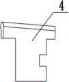
Fig. 4 is incision tool rest of the present utility model and tool rest accessory assembling schematic perspective view;
Fig. 5 is tool rest accessory front view of the present utility model;
Fig. 6 is tool rest accessory right view of the present utility model;
Fig. 7 is tool rest accessory upward view of the present utility model;
Fig. 8 is locating piece front view of the present utility model;
Fig. 9 is locating piece vertical view of the present utility model.
The specific embodiment
Below in conjunction with specific embodiment, further set forth the utility model.Should be understood that these embodiment only are used for explanation the utility model and are not used in the scope of the present utility model that limits.Should be understood that in addition those skilled in the art can make various changes or modifications the utility model after the content of having read the utility model instruction, these equivalent form of values fall within the application's appended claims institute restricted portion equally.
Shown in Fig. 1-9, the utility model relates to a kind of automotive trim strip series products crop resetting structure, comprise upper cutter seat 1, described upper cutter seat 1 is arranged on the top mold frame 8, be furnished with cutting knife 2 on the described upper cutter seat 1, the cutter head of described cutting knife 2 is furnished with the edge of a knife 13 of indent, the cutting knife face 12 of described cutting knife 2 is aimed at the cutting knife mating surface 11 of incision tool rest 3, be inserted with tool rest accessory 4 in the described incision tool rest 3 center slots, be furnished with installing hole 10 on the lower surface of described tool rest accessory 4 insertion incision tool rests 3 center slots, be furnished with locating piece 5 on the step surface of described incision tool rest 3, described incision tool rest 3 is arranged in down on the mould bases 9, guide pad 6 before being furnished with on the described mould bases 9 down, guide pad 6 aligns with the front end face of incision tool rest 3 before described, be welded with guide pad accessory 7 on the guide pad 6 before described, be furnished with spring in the described installing hole 10, described tool rest accessory 4 matches with the size of incision tool rest 3 center slots, described locating piece 5 keeps smooth smooth with the surface that preceding guide pad 6 contacts with product, and the end face of described tool rest accessory 4 can not exceed the cutting knife mating surface 11 of incision tool rest 3.
Embodiment 1
The need converted products is put into the upper surface of preceding guide pad 6 and the incision tool rest 3 of mould, spring in this moment installing hole 10 is with the certain height of upspringing of the tool rest accessory 4 in the incision tool rest 3 center slots, need converted products and locating piece 5 carry out contraposition, be adjusted to suitable position, this moment, the position to be sheared of need converted products should be under cutting knife 2, to need the side of converted products and incision tool rest 3 to clamp by tool rest accessory 4 again, and simultaneously the end that needs converted products is fixed, need this moment converted products to move, exert pressure for top mold frame 8 by punch press at last, force top mold frame 8 downward mould bases 9 to be drawn close, and drive cutting knife 2 moves downward the position to be sheared of cut-out need converted products.

Claims (5)

1. automotive trim strip series products crop resetting structure, comprise upper cutter seat (1), it is characterized in that, described upper cutter seat (1) is arranged on the top mold frame (8), be furnished with cutting knife (2) on the described upper cutter seat (1), the cutter head of described cutting knife (2) is furnished with the edge of a knife (13) of indent, the cutting knife face (12) of described cutting knife (2) is aimed at the cutting knife mating surface (11) of incision tool rest (3), be inserted with tool rest accessory (4) in the slot of described incision tool rest (3) center, be furnished with installing hole (10) on the lower surface of described tool rest accessory (4) insertion incision tool rest (3) center slot, be furnished with locating piece (5) on the step surface of described incision tool rest (3), described incision tool rest (3) is arranged in down on the mould bases (9), be furnished with preceding guide pad (6) on the mould bases (9) under described, guide pad (6) aligns with the front end face of incision tool rest (3) before described, is welded with guide pad accessory (7) on the described preceding guide pad (6).
2. a kind of automotive trim strip series products crop resetting structure according to claim 1 is characterized in that described installing hole is furnished with spring in (10).
3. a kind of automotive trim strip series products crop resetting structure according to claim 1 is characterized in that, described tool rest accessory (4) matches with the size of incision tool rest (3) center slot.
4. a kind of automotive trim strip series products crop resetting structure according to claim 1 is characterized in that, described locating piece (5) keeps smooth smooth with the surface that preceding guide pad (6) contacts with product.
5. a kind of automotive trim strip series products crop resetting structure according to claim 1 is characterized in that the end face of described tool rest accessory (4) can not exceed the cutting knife mating surface (11) of incision tool rest (3).
CN 201320043189 2013-01-24 2013-01-24 Head cutting and resetting structure of automobile decoration strip class products Expired - Fee Related CN203171716U (en)

Priority Applications (1)

Application Number Priority Date Filing Date Title
CN 201320043189 CN203171716U (en) 2013-01-24 2013-01-24 Head cutting and resetting structure of automobile decoration strip class products

Applications Claiming Priority (1)

Application Number Priority Date Filing Date Title
CN 201320043189 CN203171716U (en) 2013-01-24 2013-01-24 Head cutting and resetting structure of automobile decoration strip class products

Publications (1)

Publication Number Publication Date
CN203171716U true CN203171716U (en) 2013-09-04

Family

ID=49068467

Family Applications (1)

Application Number Title Priority Date Filing Date
CN 201320043189 Expired - Fee Related CN203171716U (en) 2013-01-24 2013-01-24 Head cutting and resetting structure of automobile decoration strip class products

Country Status (1)

Country Link
CN (1) CN203171716U (en)

Cited By (2)

* Cited by examiner, † Cited by third party
Publication number Priority date Publication date Assignee Title
CN104552448A (en) * 2014-12-05 2015-04-29 宁波福耀汽车零部件有限公司 Punching device for sealing strips for automobile foreside windscreen
WO2022095550A1 (en) * 2020-11-03 2022-05-12 宁波敏实汽车零部件技术研发有限公司 Single-module multi-position switching mechanism suitable for automobile trim strip

Cited By (3)

* Cited by examiner, † Cited by third party
Publication number Priority date Publication date Assignee Title
CN104552448A (en) * 2014-12-05 2015-04-29 宁波福耀汽车零部件有限公司 Punching device for sealing strips for automobile foreside windscreen
CN104552448B (en) * 2014-12-05 2016-06-15 宁波宏协承汽车部件有限公司 A kind of automobile front windshield sealing strip blanking units
WO2022095550A1 (en) * 2020-11-03 2022-05-12 宁波敏实汽车零部件技术研发有限公司 Single-module multi-position switching mechanism suitable for automobile trim strip

Similar Documents

Publication Publication Date Title
CN202105914U (en) Capacitor cover plate processing mold
CN204412878U (en) A kind of lateral cut structure for drawn products under diel
CN202668673U (en) Mold used in lateral cut turnup automobile decoration strip
CN203171716U (en) Head cutting and resetting structure of automobile decoration strip class products
CN203665597U (en) Punching and locating mechanism for end of trim strip
CN202963235U (en) Automobile aluminum part forming mould
CN204976732U (en) Mouth of a river machine is cut in many caves
CN202290957U (en) Joist steel cutting-off die
CN210450520U (en) Die structure of guide groove and knife beveling end
CN202606636U (en) Die oblique wedging punching device
CN201815594U (en) Structure for stamping binder surface of drawing die
CN205043875U (en) Car weather strip die
CN210847981U (en) Composite die for cutting, bending and one-step forming
CN203265470U (en) Valve key production device
CN205236765U (en) Installing support upgrades mould
CN202367077U (en) Punching die for separating vehicle wheel cover trimming
CN207288532U (en) A kind of brake dust side-cutting die
CN202861194U (en) Mobile phone upper cover stamping die
CN208867327U (en) A kind of diaphragm punching cutting die
CN110385365B (en) Panel cutting device
CN202516946U (en) Rapid die installing and regulating auxiliary device
CN207563581U (en) A kind of vehicle switch contact bridge shaping mould
CN205183485U (en) Lateral punching die
CN202507540U (en) Film tube cutting knife of film blowing machine
CN206184980U (en) It keeps off device of structure to have side suitable for unilateral blank

Legal Events

Date Code Title Description
C14 Grant of patent or utility model
GR01 Patent grant
C56 Change in the name or address of the patentee

Owner name: NINGBO HONGXIE AUTO PARTS CO., LTD.

Free format text: FORMER NAME: NINGBO FUYAO AUTOMOBILE PARTS CO., LTD.

CP03 Change of name, title or address

Address after: Beilun District of Zhejiang city in Ningbo province 315800 Kaohsiung Chen Shan Road 88, building 3, No. 1

Patentee after: NINGBO HONGXIECHENG AUTO PART CO., LTD.

Address before: 315800 No. 399 Mount Jiuhua, Beilun, Zhejiang, Ningbo (Songhua River junction)

Patentee before: Ningbo Fuyao Automobile Parts Co., Ltd.

CF01 Termination of patent right due to non-payment of annual fee

Granted publication date: 20130904

Termination date: 20190124