EP3010076A1 - Flat plate type solid oxide fuel cell stack unit and flat plate type solid oxide fuel cell stack module - Google Patents
Flat plate type solid oxide fuel cell stack unit and flat plate type solid oxide fuel cell stack module Download PDFInfo
- Publication number
- EP3010076A1 EP3010076A1 EP15152175.4A EP15152175A EP3010076A1 EP 3010076 A1 EP3010076 A1 EP 3010076A1 EP 15152175 A EP15152175 A EP 15152175A EP 3010076 A1 EP3010076 A1 EP 3010076A1
- Authority
- EP
- European Patent Office
- Prior art keywords
- fuel
- cathode
- anode
- flow channel
- output hole
- Prior art date
- Legal status (The legal status is an assumption and is not a legal conclusion. Google has not performed a legal analysis and makes no representation as to the accuracy of the status listed.)
- Granted
Links
- 239000000446 fuel Substances 0.000 title claims abstract description 281
- 239000007787 solid Substances 0.000 title claims abstract description 47
- 239000002184 metal Substances 0.000 claims abstract description 65
- 229910052751 metal Inorganic materials 0.000 claims abstract description 65
- 239000003566 sealing material Substances 0.000 claims abstract description 61
- 239000000463 material Substances 0.000 claims description 12
- 239000010410 layer Substances 0.000 description 27
- 230000015572 biosynthetic process Effects 0.000 description 8
- 229910000990 Ni alloy Inorganic materials 0.000 description 3
- 230000002708 enhancing effect Effects 0.000 description 3
- 238000012856 packing Methods 0.000 description 3
- 229910045601 alloy Inorganic materials 0.000 description 2
- 239000000956 alloy Substances 0.000 description 2
- 230000008901 benefit Effects 0.000 description 2
- 239000000919 ceramic Substances 0.000 description 2
- 238000006243 chemical reaction Methods 0.000 description 2
- 239000004020 conductor Substances 0.000 description 2
- 238000009434 installation Methods 0.000 description 2
- 238000010030 laminating Methods 0.000 description 2
- 239000011241 protective layer Substances 0.000 description 2
- 238000007789 sealing Methods 0.000 description 2
- 239000010935 stainless steel Substances 0.000 description 2
- 229910001220 stainless steel Inorganic materials 0.000 description 2
- 230000003319 supportive effect Effects 0.000 description 2
- PNEYBMLMFCGWSK-UHFFFAOYSA-N aluminium oxide Inorganic materials [O-2].[O-2].[O-2].[Al+3].[Al+3] PNEYBMLMFCGWSK-UHFFFAOYSA-N 0.000 description 1
- 230000005540 biological transmission Effects 0.000 description 1
- 229910010293 ceramic material Inorganic materials 0.000 description 1
- 230000001427 coherent effect Effects 0.000 description 1
- 229910052593 corundum Inorganic materials 0.000 description 1
- 230000005611 electricity Effects 0.000 description 1
- 238000003487 electrochemical reaction Methods 0.000 description 1
- 239000003792 electrolyte Substances 0.000 description 1
- 238000005516 engineering process Methods 0.000 description 1
- 239000011521 glass Substances 0.000 description 1
- 239000002241 glass-ceramic Substances 0.000 description 1
- 230000002401 inhibitory effect Effects 0.000 description 1
- 238000009413 insulation Methods 0.000 description 1
- 239000012774 insulation material Substances 0.000 description 1
- 239000002346 layers by function Substances 0.000 description 1
- 238000004519 manufacturing process Methods 0.000 description 1
- 239000000203 mixture Substances 0.000 description 1
- 238000007750 plasma spraying Methods 0.000 description 1
- 239000002574 poison Substances 0.000 description 1
- 231100000614 poison Toxicity 0.000 description 1
- 238000004064 recycling Methods 0.000 description 1
- 238000007650 screen-printing Methods 0.000 description 1
- 238000009834 vaporization Methods 0.000 description 1
- 230000008016 vaporization Effects 0.000 description 1
- 229910001845 yogo sapphire Inorganic materials 0.000 description 1
Images


Classifications
-
- H—ELECTRICITY
- H01—ELECTRIC ELEMENTS
- H01M—PROCESSES OR MEANS, e.g. BATTERIES, FOR THE DIRECT CONVERSION OF CHEMICAL ENERGY INTO ELECTRICAL ENERGY
- H01M8/00—Fuel cells; Manufacture thereof
- H01M8/002—Shape, form of a fuel cell
- H01M8/006—Flat
-
- H—ELECTRICITY
- H01—ELECTRIC ELEMENTS
- H01M—PROCESSES OR MEANS, e.g. BATTERIES, FOR THE DIRECT CONVERSION OF CHEMICAL ENERGY INTO ELECTRICAL ENERGY
- H01M8/00—Fuel cells; Manufacture thereof
- H01M8/04—Auxiliary arrangements, e.g. for control of pressure or for circulation of fluids
- H01M8/04082—Arrangements for control of reactant parameters, e.g. pressure or concentration
- H01M8/04201—Reactant storage and supply, e.g. means for feeding, pipes
-
- H—ELECTRICITY
- H01—ELECTRIC ELEMENTS
- H01M—PROCESSES OR MEANS, e.g. BATTERIES, FOR THE DIRECT CONVERSION OF CHEMICAL ENERGY INTO ELECTRICAL ENERGY
- H01M8/00—Fuel cells; Manufacture thereof
- H01M8/02—Details
- H01M8/0202—Collectors; Separators, e.g. bipolar separators; Interconnectors
- H01M8/0258—Collectors; Separators, e.g. bipolar separators; Interconnectors characterised by the configuration of channels, e.g. by the flow field of the reactant or coolant
- H01M8/0263—Collectors; Separators, e.g. bipolar separators; Interconnectors characterised by the configuration of channels, e.g. by the flow field of the reactant or coolant having meandering or serpentine paths
-
- H—ELECTRICITY
- H01—ELECTRIC ELEMENTS
- H01M—PROCESSES OR MEANS, e.g. BATTERIES, FOR THE DIRECT CONVERSION OF CHEMICAL ENERGY INTO ELECTRICAL ENERGY
- H01M8/00—Fuel cells; Manufacture thereof
- H01M8/02—Details
- H01M8/0271—Sealing or supporting means around electrodes, matrices or membranes
-
- H—ELECTRICITY
- H01—ELECTRIC ELEMENTS
- H01M—PROCESSES OR MEANS, e.g. BATTERIES, FOR THE DIRECT CONVERSION OF CHEMICAL ENERGY INTO ELECTRICAL ENERGY
- H01M8/00—Fuel cells; Manufacture thereof
- H01M8/02—Details
- H01M8/0271—Sealing or supporting means around electrodes, matrices or membranes
- H01M8/0273—Sealing or supporting means around electrodes, matrices or membranes with sealing or supporting means in the form of a frame
-
- H—ELECTRICITY
- H01—ELECTRIC ELEMENTS
- H01M—PROCESSES OR MEANS, e.g. BATTERIES, FOR THE DIRECT CONVERSION OF CHEMICAL ENERGY INTO ELECTRICAL ENERGY
- H01M8/00—Fuel cells; Manufacture thereof
- H01M8/10—Fuel cells with solid electrolytes
- H01M8/12—Fuel cells with solid electrolytes operating at high temperature, e.g. with stabilised ZrO2 electrolyte
- H01M8/124—Fuel cells with solid electrolytes operating at high temperature, e.g. with stabilised ZrO2 electrolyte characterised by the process of manufacturing or by the material of the electrolyte
- H01M8/1246—Fuel cells with solid electrolytes operating at high temperature, e.g. with stabilised ZrO2 electrolyte characterised by the process of manufacturing or by the material of the electrolyte the electrolyte consisting of oxides
-
- H—ELECTRICITY
- H01—ELECTRIC ELEMENTS
- H01M—PROCESSES OR MEANS, e.g. BATTERIES, FOR THE DIRECT CONVERSION OF CHEMICAL ENERGY INTO ELECTRICAL ENERGY
- H01M8/00—Fuel cells; Manufacture thereof
- H01M8/24—Grouping of fuel cells, e.g. stacking of fuel cells
-
- H—ELECTRICITY
- H01—ELECTRIC ELEMENTS
- H01M—PROCESSES OR MEANS, e.g. BATTERIES, FOR THE DIRECT CONVERSION OF CHEMICAL ENERGY INTO ELECTRICAL ENERGY
- H01M8/00—Fuel cells; Manufacture thereof
- H01M8/24—Grouping of fuel cells, e.g. stacking of fuel cells
- H01M8/241—Grouping of fuel cells, e.g. stacking of fuel cells with solid or matrix-supported electrolytes
- H01M8/2425—High-temperature cells with solid electrolytes
- H01M8/2432—Grouping of unit cells of planar configuration
-
- H—ELECTRICITY
- H01—ELECTRIC ELEMENTS
- H01M—PROCESSES OR MEANS, e.g. BATTERIES, FOR THE DIRECT CONVERSION OF CHEMICAL ENERGY INTO ELECTRICAL ENERGY
- H01M8/00—Fuel cells; Manufacture thereof
- H01M8/24—Grouping of fuel cells, e.g. stacking of fuel cells
- H01M8/2465—Details of groupings of fuel cells
- H01M8/2483—Details of groupings of fuel cells characterised by internal manifolds
-
- H—ELECTRICITY
- H01—ELECTRIC ELEMENTS
- H01M—PROCESSES OR MEANS, e.g. BATTERIES, FOR THE DIRECT CONVERSION OF CHEMICAL ENERGY INTO ELECTRICAL ENERGY
- H01M8/00—Fuel cells; Manufacture thereof
- H01M8/10—Fuel cells with solid electrolytes
- H01M8/12—Fuel cells with solid electrolytes operating at high temperature, e.g. with stabilised ZrO2 electrolyte
- H01M2008/1293—Fuel cells with solid oxide electrolytes
-
- H—ELECTRICITY
- H01—ELECTRIC ELEMENTS
- H01M—PROCESSES OR MEANS, e.g. BATTERIES, FOR THE DIRECT CONVERSION OF CHEMICAL ENERGY INTO ELECTRICAL ENERGY
- H01M2300/00—Electrolytes
- H01M2300/0017—Non-aqueous electrolytes
- H01M2300/0065—Solid electrolytes
- H01M2300/0068—Solid electrolytes inorganic
- H01M2300/0071—Oxides
-
- Y—GENERAL TAGGING OF NEW TECHNOLOGICAL DEVELOPMENTS; GENERAL TAGGING OF CROSS-SECTIONAL TECHNOLOGIES SPANNING OVER SEVERAL SECTIONS OF THE IPC; TECHNICAL SUBJECTS COVERED BY FORMER USPC CROSS-REFERENCE ART COLLECTIONS [XRACs] AND DIGESTS
- Y02—TECHNOLOGIES OR APPLICATIONS FOR MITIGATION OR ADAPTATION AGAINST CLIMATE CHANGE
- Y02E—REDUCTION OF GREENHOUSE GAS [GHG] EMISSIONS, RELATED TO ENERGY GENERATION, TRANSMISSION OR DISTRIBUTION
- Y02E60/00—Enabling technologies; Technologies with a potential or indirect contribution to GHG emissions mitigation
- Y02E60/30—Hydrogen technology
- Y02E60/50—Fuel cells
-
- Y—GENERAL TAGGING OF NEW TECHNOLOGICAL DEVELOPMENTS; GENERAL TAGGING OF CROSS-SECTIONAL TECHNOLOGIES SPANNING OVER SEVERAL SECTIONS OF THE IPC; TECHNICAL SUBJECTS COVERED BY FORMER USPC CROSS-REFERENCE ART COLLECTIONS [XRACs] AND DIGESTS
- Y02—TECHNOLOGIES OR APPLICATIONS FOR MITIGATION OR ADAPTATION AGAINST CLIMATE CHANGE
- Y02P—CLIMATE CHANGE MITIGATION TECHNOLOGIES IN THE PRODUCTION OR PROCESSING OF GOODS
- Y02P70/00—Climate change mitigation technologies in the production process for final industrial or consumer products
- Y02P70/50—Manufacturing or production processes characterised by the final manufactured product
Definitions
- the invention relates to a flat plate type solid oxide fuel cell stack unit and flat plate type solid oxide fuel cell stack module, and more particularly to the cell stack unit and the cell stack module that are characterized on a reduced size, high efficiency, easy packing and assembly, and can easily and modularly vary the stack arrangement so as to meet the different specifications of the generation systems.
- the solid oxide fuel cell is an energy conversion apparatus that utilizes the electrochemical reaction to convert the fuel into the respective electric energy for output.
- the energy conversion efficiency of the SOFC generation system can be raised up to 80-90%.
- the application size of the SOFC generation system can be small or portable sized for household, medical facilities, communities and so on, and may be large sized to serve a generation plant.
- the conventional SOFC stack is assembled by laminating with end plates, panel frames, cell units, seal materials and metal contact layers. Obviously, such a manufacturing process is complicated and can only produce a larger-size cell stack module. Hence, the complexity in assembling the aforesaid conventional SOFC stack would be inevitable, and also the generation system having the SOFC stack is quite possible to have a low electric generation per unit volume.
- the flat plate type solid oxide fuel cell stack unit comprises an anode plate, a cathode plate, a cell unit, an anode metal net, a cathode metal net, at least one anode sealing material and at least one cathode sealing material.
- the anode plate formed as a rectangle has a first flow channel structured on a surface thereof, four first fuel input holes located respectively to four corners thereof, and a first fuel output hole located at a center thereof.
- the cathode plate shaped as a rectangle has a second flow channel structured on a surface thereof, four second fuel input holes located at respective corners thereof, a second fuel output hole located at a center thereof, a plurality of second air input grooves disposed along a lateral side thereof, and a plurality of second air output grooves disposed along another lateral side thereof opposing to the lateral side, wherein the second air input grooves, the second air output grooves and the second flow channel are all communicative in space.
- the cell unit shaped as a rectangle has four third fuel input holes located at respective corners thereof, a third fuel output hole located at a center thereof, a cathode layer disposed at one side thereof to face the second flow channel, an anode layer disposed at another side thereof opposing to the side to face the first flow channel, wherein the four first fuel input holes, the four second fuel input holes and the four third fuel input holes are aligned respectively in positions, wherein the first fuel output hole, the second fuel output hole and the third fuel output hole are aligned respectively in positions.
- the anode metal net is located between the anode plate and the cell unit.
- the cathode metal net is located between the cathode plate and the cell unit.
- the at least one anode sealing material is disposed between the anode plate and the cell unit to surround the first fuel input holes, the first fuel output hole, the first flow channel, the cell unit and the anode metal net.
- the at least one cathode sealing material is disposed between the cathode plate and the cell unit to surround the second fuel input holes, the second fuel output hole, the second flow channel, the cell unit and the cathode metal net.
- the flat plate type solid oxide fuel cell stack module is obtained by stacking a plurality of the aforesaid flat plate type solid oxide fuel cell stack units.
- the flat plate type solid oxide fuel cell stack module comprises an anode plate, a cathode plate, a plurality of connection plates and a plurality of cell sets.
- the anode plate formed as a rectangle has a first flow channel structured on a surface thereof, four first fuel input holes located respectively to four corners thereof, and a first fuel output hole located at a center thereof.
- the cathode plate shaped as a rectangle has a second flow channel structured on a surface thereof, four second fuel input holes located at respective corners thereof, a second fuel output hole located at a center thereof, a plurality of second air input grooves disposed along a lateral side thereof, and a plurality of second air output grooves disposed along another lateral side thereof opposing to the lateral side, wherein the second air input grooves, the second air output grooves and the second flow channel are all communicative in space.
- connection plates is shaped as a rectangle and has four eighth fuel input holes located at respective corners thereof, an eighth fuel output hole located at a center thereof, an anode flow channel area disposed on one side thereof, a cathode flow channel area disposed on another side thereof opposing to the side, a plurality of eighth air input grooves disposed along a lateral side of the side thereof having the cathode flow channel area, and a plurality of eighth air output grooves disposed along another lateral side thereof opposing to the lateral side, wherein the eight air input grooves, the eight air output grooves and the cathode flow channel area are all communicative in space.
- Each of the cell units further includes an anode metal net, a cathode metal net, at least one anode sealing material and at least one cathode sealing material.
- the cell unit shaped as a rectangle has four third fuel input holes located at respective corners thereof, a third fuel output hole located at a center thereof, a cathode layer disposed on one side thereof and an anode layer disposed on another side thereof opposing to the side.
- the anode metal net is located between the anode plate and the cell unit.
- the cathode metal net is located between the cathode plate and the cell unit.
- the at least one anode sealing material is disposed on the side of the cell unit having the anode layer.
- the at least one cathode sealing material is disposed on the side of the cell unit having the cathode layer.
- one of the cell units is disposed between the anode plate and one of the connection plates, the anode sealing material of this cell unit is to surround the corresponding first fuel input holes, the corresponding first fuel output hole, the corresponding first flow channel, this cell unit and the corresponding anode metal net, and the cathode sealing material of this cell unit is to surround the corresponding eighth fuel input holes, the corresponding eighth fuel output hole, the corresponding cathode flow channel area, this cell unit and the corresponding cathode metal net.
- another one of the cell units is disposed between the cathode plate and another one of the connection plates, the anode sealing material of this cell unit is to surround the corresponding eighth fuel input holes, the corresponding eighth fuel output hole, the corresponding anode flow channel area, this cell unit and the corresponding anode metal net, and the cathode sealing material of this cell unit is to surround the corresponding second fuel input holes, the corresponding second fuel output hole, the corresponding second flow channel, this cell unit and the corresponding cathode metal net.
- one of the cell units is disposed between two neighboring said connection plates, the anode sealing material of this cell unit is to surround the corresponding eighth fuel input holes, the corresponding eighth fuel output hole, the corresponding anode flow channel area, this cell unit and the corresponding anode metal net, and the cathode sealing material of this cell unit is to surround the corresponding eighth fuel input holes, the corresponding eighth fuel output hole, the corresponding cathode flow channel area, this cell unit and the corresponding cathode metal net.
- the anode layer of each of the cell units is to face the first flow channel of the corresponding anode plate and the cathode layer of each of the cell units is to face the second flow channel of the corresponding cathode plate.
- the first fuel input holes, the second fuel input holes, the plurality of third fuel input holes and the plurality of eighth fuel input holes are aligned in respective positions
- the first fuel output holes, the second fuel output holes, the third fuel output holes and the eighth fuel output holes are aligned in respective positions
- the second air input grooves and the eighth air input grooves are aligned in respective positions
- the second air output grooves and the eighth air output grooves are aligned in respective positions.
- the invention disclosed herein is directed to a flat plate type solid oxide fuel cell stack unit and a flat plate type solid oxide fuel cell stack module.
- numerous details are set forth in order to provide a thorough understanding of the present invention. It will be appreciated by one skilled in the art that variations of these specific details are possible while still achieving the results of the present invention. In other instance, well-known components are not described in detail in order not to unnecessarily obscure the present invention.
- the cell stack unit 100 includes an anode plate 10, a cathode plate 20, a cell unit 30, two sets of anode sealing materials 40, an anode metal net 50, a cathode metal net 60 and two sets of cathode sealing materials 70.
- the anode plate 10 formed as a rectangular plate has a first flow channel 14 structured on the top surface thereof, four first fuel input holes 11 located respectively to four corners thereof, and a first fuel output hole 12 located at the center thereof surrounded by the four first fuel input holes 11.
- the first fuel input holes 11 and the first fuel output hole 12 are all through holes communicating both sides of the anode plate 10.
- the first flow channel 14 is structured with a plurality of first bumps 13 on the top surface of anode plate 10 in FIG.4 , where the plurality of first bumps 13 are arranged to encircle the first fuel output hole 12.
- the plurality of first bumps 13 are arranged symmetrically along circles with different radiuses to the center point of the first fuel output hole 12.
- the anode plate 10A has four first fuel input holes 11A, a first fuel output hole 12A, a plurality of first bumps 13A and a first flow channel 14A.
- the anode plate 10B has four first fuel input holes 11B, a first fuel output hole 12B, a plurality of first bumps 13B and a first flow channel 14B.
- the anode plate 10C has four first fuel input holes 11C, a first fuel output hole 12C, a plurality of first bumps 13C and a first flow channel 14C.
- the anode plate 10D has four first fuel input holes 11D, a first fuel output hole 12D, a plurality of first bumps 13D and a first flow channel 14D.
- the anode plate 10E has four first fuel input holes 11E, a first fuel output hole 12E, a plurality of first bumps 13E and a first flow channel 14E.
- the anode plate 10F has four first fuel input holes 11F, a first fuel output hole 12F, a plurality of first bumps 13F and a first flow channel 14F.
- the major difference between any of the anode plates 10A ⁇ 10F of FIG.5 ⁇ FIG.10 and the anode plate 10 of FIG.4 is the difference of the arrangement and the formation of the first bumps 13 ⁇ 13F. Nevertheless, no matter what kind of the arrangement and the formation of the first bumps is, all these first bumps 13, 13A ⁇ 13F are all surrounding the first fuel output hole 12 ⁇ 12F in a symmetrical manner. Upon such an arrangement, the flow field on the anode plate 10 ⁇ 10F can be evenly distributed.
- any of the anode plates 10 ⁇ 10F of FIG.4 ⁇ FIG.10 is rectangular shaped with the four first fuel input holes 11 ⁇ 11F located to the four corners, and with the fuel output holes 12 ⁇ 12F at the center thereof, such that the arrangement of the first bumps 13 ⁇ 13F in accordance with the symmetrical manner can be easily provided.
- the anode plate is other shaped, then the fuel input holes and the fuel output hole shall be embodied in a pattern other than any of FIG.4 ⁇ FIG.10 .
- the formation of the first bumps shall not be limited to that in any of FIG.4 ⁇ FIG.10 .
- any formation of the first bumps can be a candidate if and only if the formation of the bumps can achieve the goal of an even-distributed flow field.
- part of the first bumps 13 can be treated as supportive nodes for enhancing the structural strength and for bifurcating and disturbing the flow in the first flow channel 14 ⁇ 14F.
- the cathode plate 20 shaped as a rectangle has a second flow channel 24 structured on the top surface thereof, four second fuel input holes 21 located at respective corners thereof and a second fuel output hole 22 located at the center thereof.
- the plurality of second fuel input holes 21 are to surround the second fuel output hole 22, and the second fuel input holes 21 and the second fuel output hole 22 are all through holes for communicating both sides of the cathode plate 20.
- the second flow channel 24 is configured by a plurality of second bumps 23, in which the plurality of second bumps 23 are arranged to encircle the second fuel output hole 22.
- the plurality of second bumps 23 are arranged symmetrically along circles with different radiuses to the center point of the second fuel output hole 22.
- a plurality of second air input grooves 25 are disposed, while a plurality of second air output grooves 26 are disposed along the opposing lateral side thereof.
- the second air input grooves 25, the second air output grooves 26 and the second flow channel 24 are all communicative in space.
- the second bumps 23 include various shapes of bumps, such as a plurality of parallel longitudinal strips extending in a direction parallel to the second air input grooves 25 and the second air output grooves 26, such that the air can smoothly flow from the second air input grooves 25, through the second flow channel 24, and finally to the second air output grooves 26.
- the cathode plate 20A has four second fuel input holes 21A, a second fuel output hole 22A, a plurality of second bumps 23A, a second flow channel 24A, a plurality of second air input grooves 25A and a plurality of second air output grooves 26A.
- the cathode plate 20B has four second fuel input holes 21B, a second fuel output hole 22B, a plurality of second bumps 23B, a second flow channel 24B, a plurality of second air input grooves 25A and a plurality of second air output grooves 26A.
- the major difference between any of the cathode plates 20A ⁇ 10B of FIG.12 ⁇ FIG.13 and the cathode plate 20 of FIG.11 is the difference of the arrangement and the formation of the second bumps 23 ⁇ 23F. Nevertheless, no matter what kind of the arrangement and the formation of the second bumps is, all these second bumps 23 ⁇ 23B are all surrounding the second fuel output hole 22 ⁇ 22A in a symmetrical manner including parallel longitudinal strip or island structures. In particular, the extending direction of these island structures are parallel to that of the second air input grooves 25A, 25B and the second air output grooves 26A, 26B. Upon such an arrangement, the flow field on the cathode plate 20 ⁇ 20B can be evenly distributed.
- the cathode plates 20 ⁇ 20B are rectangular shaped, the four second fuel input holes 21 ⁇ 21B are located to respective corners, the second fuel output holes 22 ⁇ 22B are centrally located, the second air input grooves 25 ⁇ 25B, and the second air output grooves 26 ⁇ 26B are parallel extending.
- the second bumps 23 ⁇ 23B are symmetrically arranged and in a longitudinal island structures. Namely, Namely, if the cathode plate is other shaped, then the fuel input holes, the fuel output hole, the air input grooves and the air output grooves shall be embodied in a pattern other than any of FIG. 11 ⁇ FIG.13 .
- the formation of the second bumps shall not be limited to that in any of FIG. 11 ⁇ FIG.13 .
- part of the second bumps 23 can be treated as supportive nodes for enhancing the structural strength and for bifurcating and disturbing the flow in the second flow channel 24 ⁇ 24B.
- the material for the anode plates 10 ⁇ 10F of FIG.4 ⁇ FIG.10 and the cathode plates 20 ⁇ 20B of FIG. 11 ⁇ FIG. 13 can be one of a high temperature alloy and an electric conductive material, such as a high nickel alloy, a stainless steel 441, a Crofer 22 and so on.
- the cell unit 30 formed as a rectangle has four third fuel input holes 31 located at respective corners thereof and a third fuel output hole 32 located at the center thereof.
- the plurality of third fuel input holes 31 are to surround the third fuel output hole 32, and the third fuel input holes 31 and the third fuel output hole 32 are all through holes for communicating both sides of the cell unit 30.
- Two opposing sides of the cell unit 30 are disposed with a cathode layer 33 and an anode layer 34, respectively.
- An electrolyte layer 35 is disposed between the cathode layer 33 and the anode layer 34.
- the anode plate 10 is mounted onto the cell unit 30 at the side having the anode layer 34 in a manner of the first flow channel 14 facing the anode layer 34.
- the cathode plate 20 is mounted onto the cell unit 30 at the side having the cathode layer 33 in a manner of the second flow channel 24 facing the cathode layer 33.
- the cell unit 30 is mainly to fit a generation system, and thus the shape thereof is not limited to the aforesaid rectangle. If the cell unit 30 is other shaped, shapes of the anode plate 10 ⁇ 10F of FIG.4 ⁇ FIG.10 and the cathode plate 20 ⁇ 20B of FIG.11 ⁇ FIG.13 are varied accordingly.
- the cell unit 30 can be an anode-supported planar SOFC or an electrolyte-supported planar SOFC.
- the cell unit 30 can have (but not limited to) a size of 10.8cmx10.8cm.
- the anode metal net 50 formed as a rectangle to be mounted onto the anode layer 34 of the cell unit 30 has four cutouts 51 at respective corners thereof and a hole 52 at the center thereof.
- the hole 52 is to avoid possible installation interference between the anode metal net 50 and the anode sealing material 40.
- candidate shape for the anode metal net 50 is not limited to the shape shown in the illustrated embodiment, but is to satisfy the criterion that is able to contact the anode layer 34 of the cell unit 30 without influencing the inflow and outflow of the fuel.
- the cathode metal net 60 formed as a rectangle to be mounted onto the cathode layer 33 of the cell unit 30 has four cutouts 61 at respective corners thereof and a hole 62 at the center thereof.
- the hole 62 is to avoid possible installation interference between the cathode metal net 60 and the cathode sealing material 70.
- candidate shape for the cathode metal net 60 is not limited to the shape shown in the illustrated embodiment, but is to satisfy the criterion that is able to contact the cathode layer 33 of the cell unit 30 without influencing the inflow and outflow of the fuel.
- the anode sealing material 40 disposed between the anode plate 10 and the cell unit 30 is consisted of a rectangular frame portion 41 and a circular portion 42.
- the rectangular frame portion 41 has four corners to dispose fourth respective fuel input holes 411.
- a fourth fuel output hole 421 is disposed at the center of the circular portion 42.
- the cathode sealing material 70 disposed between the cathode plate 20 and the cell unit 30 is consisted of two longitudinal portions 71, a plurality of rectangular portions 72 and a circular portion 73, in which the two longitudinal portions 71 and the plurality of rectangular portions 72 are integrated to form a hollow rectangular frame having four corners disposed with respective seventh fuel input holes 711. Between every two neighboring rectangular portions, a passage 721 is formed. A seventh fuel output hole 731 is disposed at the center of the circular portion 73.
- the anode sealing material 40 and the cathode sealing material 70 are to serve an air-tight purpose for the engagement of the anode plate 10, the cell unit 30 and the cathode plate 20 so as to be insulated from the anode metal net 50 and the cathode metal net 60.
- the anode sealing material 40 and the cathode sealing material 70 can be made of a ceramic material, a mixed material of ceramics and glass, or a proper insulation material such as Al 2 O 3 or SiO 2 -B 2 O 3 -Al 2 O 3 -BaO glass-ceramics.
- shapes of the anode sealing material 40 and cathode sealing material 70 are not limited to the illustrated embodiments.
- an acceptable shape should meet the characteristics of surrounding the first fuel input holes 11, the first fuel output hole 12, the first flow channel 13, the cell unit 30 and the anode metal net 50, not to interference inflow and outflow of the fuel, sealing tightly the anode plate 10 and the cell unit 30, and insulating the anode metal net 50.
- an acceptable shape should meet the characteristics of surrounding the second fuel input holes 21, the second fuel output hole 22, the second flow channel 24, the cell unit 30 and the cathode metal net 60, not to interference the input and output of the air and the fuel, sealing tightly the cathode plate 20 and the cell unit 30, and insulating the cathode metal net 60.
- FIG.2 and FIG.3 two sets of the anode sealing material 40 and two sets of the cathode sealing material 70 are included.
- the application of the anode sealing material 40 and the cathode sealing material 70 are various in shapes and numbers, but meet the practical needs.
- the anode plate 10, the anode sealing material 40, the anode metal net 50, the cell unit 30, the cathode metal net 60, the cathode sealing material 70 and the cathode plate 20 are laminated in order, in which the first fuel input holes 11, the fourth fuel input holes 411, the third fuel input holes 31, the seventh fuel input holes 711, and the second fuel input holes 21 should be aligned in positions, and also the first fuel output hole 12, the fourth fuel output hole 421, the third fuel output hole 32, the seventh fuel output hole 731, and the second fuel output hole 22 shall be aligned in positions (referred also to FIG.2 .
- the air flows in the cell stack unit 100 via the second air input grooves 25, through cathode metal net 60, and out of the cell stack unit 100 via the second air output grooves 26 (as the dash-arrowed path).
- the fuel can flow in the cell stack unit 100 via the first fuel input holes 11, through the anode metal net 50, and leave the cell stack unit 100 via the first fuel output hole 12 (as the solid-arrowed path).
- the material for the seal material 27 is not limited to a specific one, and can adopt the same material for the cathode plate 20, a metal or ceramics with a sealing material for inhibiting leak of the fuel.
- the cell stack module 100A is produced by stacking a plurality the cell stack units 100 of FIG.1 in a laminating manner. Each of the cell stack units 100 is piled by having the anode plate 10 as the bottom to top the cathode plate 20 of a lower cell stack unit 100.
- the seal material 27 is disposed into the second fuel input holes 21 and the second fuel output hole 22 of the top cathode plate 20 so as to all the fuel input holes and the fuel output holes of the cell stack module 100A to be communicative in space.
- the fuel enters each of the cell stack units 100 from the respective first fuel input holes 11, flows through the respective anode metal nets 50, and then leave the cell stack module 100A via the first fuel output hole 12 at the bottom of the cell stack module 100A (as the solid-arrowed path).
- the cell stack module 200 includes an anode plate 10, a cathode plate 20, a plurality of connection plates 80 and a plurality of cell sets 90. In this embodiment with three cell sets 90, two connection plates 80 are required to separate the cells. It is noted that the anode plate 10 and the cathode plate 20 are structured as the same as the corresponding anode plate 10 and cathode plate 20 of FIG.2 .
- connection plate 80 shaped as a rectangle has four eighth fuel input holes 81 located at respective corners thereof and an eighth fuel output hole 82 located at the center thereof.
- the plurality of eighth fuel input holes 81 are to surround the eighth fuel output hole 32, and the eighth fuel input holes 81 and the eighth fuel output hole 82 are all through holes for communicating both sides of the connection plate 80.
- Two opposing sides of the connection plate 80 are defined as an anode flow channel area 83 and a cathode flow channel area 84, respectively.
- the anode flow channel area 83 is disposed with a plurality of anode bumps 831, where the plurality of anode bumps 831 encircle the eighth fuel output hole 82 in a manner of being arranged symmetrically along circles with different radiuses to the center point of the eighth fuel output hole 82.
- a plurality of cathode bumps 841 are disposed, where the plurality of cathode bumps 841 encircle the eighth fuel output hole 82 in a manner of being arranged symmetrically along circles with different radiuses to the center point of the eighth fuel output hole 82.
- connection plate 80 At a lateral side of the connection plate 80 on the surface defining the cathode flow channel area 84, a plurality of parallel eighth air input grooves 85 are constructed. At the other lateral side on the same surface of the connection plate 80, a plurality of parallel eighth air output grooves 86 are constructed by opposing to the eighth air input grooves 85.
- the eighth air input grooves 85, the eighth air output grooves 86 and the cathode flow channel area 84 are all communicative in space.
- the cathode bumps 841 may be various formed, including a plurality of parallel longitudinal island structures extending parallel to the eighth air input grooves 8 and the eighth air output grooves 86.
- the cathode flow channel area 84 can be embodied as that of the cathode plate 20.
- the connection plate 80 can be one of a high temperature alloy and an electric conductive material, such as a high nickel alloy, a stainless steel 441, a Crofer 22 and so on.
- the anode flow channel area 83 can be structured by resembling to the first flow channel 14 of the anode plate 10.
- the cathode flow channel area 84 can be structured by resembling to the second flow channel 24 of the cathode plate 20.
- the cell set 90 includes a cell unit 30, two anode sealing materials 40, an anode metal net 50, a cathode metal net 60 and two cathode sealing materials 70.
- the cell unit 30, the anode sealing material 40, the anode metal net 50, the cathode metal net 60 and the cathode sealing material 70 of this embodiment can be engineered by resembling to the cell unit 30, the anode sealing material 40, the anode metal net 50, the cathode metal net 60 and the cathode sealing material 70 of FIG.2 .
- the lower cell set 90 is disposed between the anode plate 10 and the lower connection plate 80.
- the anode sealing material 40 of the cell set 90 is mounted to surround the first fuel input holes 11, the first fuel output hole 12, the first flow channel 14, the cell unit 30 and the anode metal net 50.
- the cathode sealing material 70 of the cell set 90 is mounted to surround the eighth fuel input holes 81, the eighth fuel output hole 82, the cathode flow channel area 84, the cell unit 30 and the cathode metal net 60.
- the upper cell set 90 is disposed between the cathode plate 20 and the upper connection plate 80.
- the anode sealing material 40 of the cell set 90 is mounted to surround the eighth fuel input holes 81, the eighth fuel output hole 82, the anode flow channel area 83, the cell unit 30 and the anode metal net 50.
- the cathode sealing material 70 of the cell set 90 is mounted to surround the second fuel input holes 21, the second fuel output hole 22, the second flow channel 24, the cell unit 30 and the cathode metal net 60.
- the third cell set 90 of this embodiment is disposed between the two connection plates 80.
- the anode sealing material 40 of the cell set 90 is mounted to surround the eighth fuel input holes 81, the eighth fuel output hole 82, the anode flow channel area 83, the cell unit 30 and the anode metal net 50.
- the cathode sealing material 70 of the cell set 90 is mounted to surround the eighth fuel input holes 81, the eighth fuel output hole 82, the cathode flow channel area 84, the cell unit 30 and the cathode metal net 60.
- Each the anode layer 34 of the cell unit 30 is to face the anode plate 10 at the surface having the first flow channel 14, while each the cathode layer of the cell unit 30 is to face the cathode plate 20 at the surface having the second flow channel 24.
- the first fuel input holes 11, the second fuel input holes 21, the third fuel input holes 31 and the eighth fuel input holes 81 are aligned, respectively.
- the first fuel output hole 12, the second fuel output hole 22, the third fuel output hole 32 and the eighth fuel output hole 82 are aligned as well.
- the second air input holes 25 and the eighth air input holes 85 are aligned in position, while the second air output hole 26 and the eighth air output hole 86 are aligned, respectively.
- the second fuel input holes 21 and second fuel output hole 22 should be disposed with corresponding seal materials (not shown in the figure), and the fuel enters the cell stack module 200 via the first fuel input holes 11, then flows through every anode layer 34 of the corresponding cell unit 30, and finally leaves the cell stack module 200 via the first fuel output hole 12.
- the piling of three flat plate type solid oxide fuel cell stack units 100 of FIG.1 can also produce an apparatus resembling functionally to the flat plate type solid oxide fuel cell stack module 200 of FIG.22 .
- the thickness of the apparatus of FIG.21 would be larger.
- the connection plate 80 exists to replace the anode plate 10 and the neighboring cathode plate 20 of FIG.21 , such that the thickness of the flat plate type solid oxide fuel cell stack module 200 of FIG.22 can be substantially reduced.
- a protective layer shall be coated onto the surfaces of the cathode plate 20 and the cathode flow channel area 84 of the connection plate 80.
- Such a protective layer can be produced by screen-printing or plasma spraying a mixture of LSM, MnCo and perovskite so as to inhibit the vaporization of the Cr.
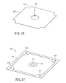
- FIG.27 a multi-unit cell stack module 300 is shown.
- Basic structuring for the cell stack module 300 is the same as that for the cell stack module 200 of FIG.22 .
- the cell stack module 300 includes one anode plate 10 as the bottom, one cathode plate 20 as the top, a plurality of the connection plates 80 and a plurality of the cell sets separated by the connection plates 80. From the descriptions of FIG.22 and FIG.27 , it is understood that, if the cell units 30 has a number N, then the number for the connection plates 80 would be N-1. Therefore, the embodiment of FIG.22 is disposed with three cell units 30 and two connection plates 80, and the embodiment of FIG.27 is disposed with 30 cell units 30 and 29 connection plates 80.
- the thickness of the anode plate 10 may be about 3 ⁇ 5mm, that of the cathode plate 20 may be about ⁇ 5mm, and that of the connection plate 80 may be about 2 ⁇ 3mm. Then, for the cell stack module of FIG.25 , the optimal performance contributed by coherent individual stack performance can be obtained at a loading of 20 ⁇ 50kg and an average stress of about 0.083 ⁇ 0.208kg/cm 2 .
- the fuel input holes are all to surround the fuel output hole.
- the reason for that is based on the consideration of even distribution of the incoming fuel.
- these two kinds of holes can be switched over in positions.
- the fuel output holes can be arranged to surround the fuel input hole.
- the flat plate type solid oxide fuel cell stack unit and the flat plate type solid oxide fuel cell stack module in accordance with the present invention are provided with advantages in a minimized volume, high efficiency, easy packing and assembling and can easily and modularly vary the stack arrangement so as to meet the specification needs of a generation system, Further, for the fuel input and output holes are all planar, so the objects in assembling, moving, loading and packing can be easily achieved. Also, while in application, the number of the cell units for stacking is not limited specifically, even that an optimal performance is demanded.
Abstract
Description
- This application claims the benefit of Taiwan Patent Application Serial No.
103135990, filed October 21, 2014 - The invention relates to a flat plate type solid oxide fuel cell stack unit and flat plate type solid oxide fuel cell stack module, and more particularly to the cell stack unit and the cell stack module that are characterized on a reduced size, high efficiency, easy packing and assembly, and can easily and modularly vary the stack arrangement so as to meet the different specifications of the generation systems.
- The solid oxide fuel cell (SOFC) is an energy conversion apparatus that utilizes the electrochemical reaction to convert the fuel into the respective electric energy for output. By further introducing an exhausted heat recycling system, the energy conversion efficiency of the SOFC generation system can be raised up to 80-90%. Further, the application size of the SOFC generation system can be small or portable sized for household, medical facilities, communities and so on, and may be large sized to serve a generation plant. Thus, all major countries in the world have been devoted huge money into developing the related technology of the SOFCs.
- In order to produce more electricity while in applying the ordinary flat plate type SOFC stack, a pile of more than 10 SOFC units are usually laminated together to form a SOFC stack by proper in-serial connections among these SOFC units.
- In the art, the conventional SOFC stack is assembled by laminating with end plates, panel frames, cell units, seal materials and metal contact layers. Obviously, such a manufacturing process is complicated and can only produce a larger-size cell stack module. Hence, the complexity in assembling the aforesaid conventional SOFC stack would be inevitable, and also the generation system having the SOFC stack is quite possible to have a low electric generation per unit volume.
- Accordingly, it is the primary object of the present invention to provide a flat plate type solid oxide fuel cell stack unit and a flat plate type solid oxide fuel cell stack module, each of which is characterized on a reduced size, high efficiency and easy assembly and can easily and modularly vary the stack arrangement so as to enhance the merchandise competence of the SOFC products.
- In the present invention, the flat plate type solid oxide fuel cell stack unit comprises an anode plate, a cathode plate, a cell unit, an anode metal net, a cathode metal net, at least one anode sealing material and at least one cathode sealing material.
- The anode plate formed as a rectangle has a first flow channel structured on a surface thereof, four first fuel input holes located respectively to four corners thereof, and a first fuel output hole located at a center thereof.
- The cathode plate shaped as a rectangle has a second flow channel structured on a surface thereof, four second fuel input holes located at respective corners thereof, a second fuel output hole located at a center thereof, a plurality of second air input grooves disposed along a lateral side thereof, and a plurality of second air output grooves disposed along another lateral side thereof opposing to the lateral side, wherein the second air input grooves, the second air output grooves and the second flow channel are all communicative in space.
- The cell unit shaped as a rectangle has four third fuel input holes located at respective corners thereof, a third fuel output hole located at a center thereof, a cathode layer disposed at one side thereof to face the second flow channel, an anode layer disposed at another side thereof opposing to the side to face the first flow channel, wherein the four first fuel input holes, the four second fuel input holes and the four third fuel input holes are aligned respectively in positions, wherein the first fuel output hole, the second fuel output hole and the third fuel output hole are aligned respectively in positions.
- The anode metal net is located between the anode plate and the cell unit.
- The cathode metal net is located between the cathode plate and the cell unit.
- The at least one anode sealing material is disposed between the anode plate and the cell unit to surround the first fuel input holes, the first fuel output hole, the first flow channel, the cell unit and the anode metal net.
- The at least one cathode sealing material is disposed between the cathode plate and the cell unit to surround the second fuel input holes, the second fuel output hole, the second flow channel, the cell unit and the cathode metal net.
- In the present invention, the flat plate type solid oxide fuel cell stack module is obtained by stacking a plurality of the aforesaid flat plate type solid oxide fuel cell stack units.
- Accordingly, the flat plate type solid oxide fuel cell stack module comprises an anode plate, a cathode plate, a plurality of connection plates and a plurality of cell sets.
- The anode plate formed as a rectangle has a first flow channel structured on a surface thereof, four first fuel input holes located respectively to four corners thereof, and a first fuel output hole located at a center thereof.
- The cathode plate shaped as a rectangle has a second flow channel structured on a surface thereof, four second fuel input holes located at respective corners thereof, a second fuel output hole located at a center thereof, a plurality of second air input grooves disposed along a lateral side thereof, and a plurality of second air output grooves disposed along another lateral side thereof opposing to the lateral side, wherein the second air input grooves, the second air output grooves and the second flow channel are all communicative in space.
- Each of the connection plates is shaped as a rectangle and has four eighth fuel input holes located at respective corners thereof, an eighth fuel output hole located at a center thereof, an anode flow channel area disposed on one side thereof, a cathode flow channel area disposed on another side thereof opposing to the side, a plurality of eighth air input grooves disposed along a lateral side of the side thereof having the cathode flow channel area, and a plurality of eighth air output grooves disposed along another lateral side thereof opposing to the lateral side, wherein the eight air input grooves, the eight air output grooves and the cathode flow channel area are all communicative in space.
- Each of the cell units further includes an anode metal net, a cathode metal net, at least one anode sealing material and at least one cathode sealing material.
- The cell unit shaped as a rectangle has four third fuel input holes located at respective corners thereof, a third fuel output hole located at a center thereof, a cathode layer disposed on one side thereof and an anode layer disposed on another side thereof opposing to the side.
- The anode metal net is located between the anode plate and the cell unit.
- The cathode metal net is located between the cathode plate and the cell unit.
- The at least one anode sealing material is disposed on the side of the cell unit having the anode layer.
- The at least one cathode sealing material is disposed on the side of the cell unit having the cathode layer.
- In this cell stack module, one of the cell units is disposed between the anode plate and one of the connection plates, the anode sealing material of this cell unit is to surround the corresponding first fuel input holes, the corresponding first fuel output hole, the corresponding first flow channel, this cell unit and the corresponding anode metal net, and the cathode sealing material of this cell unit is to surround the corresponding eighth fuel input holes, the corresponding eighth fuel output hole, the corresponding cathode flow channel area, this cell unit and the corresponding cathode metal net.
- In this cell stack module, another one of the cell units is disposed between the cathode plate and another one of the connection plates, the anode sealing material of this cell unit is to surround the corresponding eighth fuel input holes, the corresponding eighth fuel output hole, the corresponding anode flow channel area, this cell unit and the corresponding anode metal net, and the cathode sealing material of this cell unit is to surround the corresponding second fuel input holes, the corresponding second fuel output hole, the corresponding second flow channel, this cell unit and the corresponding cathode metal net.
- In this cell stack module, one of the cell units is disposed between two neighboring said connection plates, the anode sealing material of this cell unit is to surround the corresponding eighth fuel input holes, the corresponding eighth fuel output hole, the corresponding anode flow channel area, this cell unit and the corresponding anode metal net, and the cathode sealing material of this cell unit is to surround the corresponding eighth fuel input holes, the corresponding eighth fuel output hole, the corresponding cathode flow channel area, this cell unit and the corresponding cathode metal net.
- In this cell stack module, the anode layer of each of the cell units is to face the first flow channel of the corresponding anode plate and the cathode layer of each of the cell units is to face the second flow channel of the corresponding cathode plate.
- In this cell stack module, the first fuel input holes, the second fuel input holes, the plurality of third fuel input holes and the plurality of eighth fuel input holes are aligned in respective positions, the first fuel output holes, the second fuel output holes, the third fuel output holes and the eighth fuel output holes are aligned in respective positions, the second air input grooves and the eighth air input grooves are aligned in respective positions, and the second air output grooves and the eighth air output grooves are aligned in respective positions.
- All these objects are achieved by the flat plate type solid oxide fuel cell stack unit and the flat plate type solid oxide fuel cell stack module described below.
- The present invention will now be specified with reference to its preferred embodiment illustrated in the drawings, in which:
-
FIG.1 is a schematic perspective view of a preferred embodiment of the flat plate type solid oxide fuel cell stack unit in accordance with the present invention; -
FIG.2 is a schematic exploded view ofFIG.1 ; -
FIG.3 is another view ofFIG.2 ; -
FIG.4 shows the anode plate ofFIG. 1 ; -
FIG.5 through FIG.10 demonstrate other embodiments of the anode plate in accordance with the present invention; -
FIG.11 shows the cathode plate ofFIG.1 ; -
FIG.12 and FIG.13 demonstrate two other embodiments of the cathode plate in accordance with the present invention; -
FIG.14 shows the cell unit ofFIG. 1 ; -
FIG.15 shows the anode metal net ofFIG. 1 ; -
FIG.16 shows the cathode metal net ofFIG 1 ; -
FIG.17 shows the anode sealing material ofFIG.1 ; -
FIG.18 shows the cathode sealing material ofFIG.1 ; -
FIG. 19 is a cross-sectional view ofFIG.1 along line A-A; -
FIG.20 is a cross-sectional view ofFIG.1 along line B-B; -
FIG.21 is a schematic cross-sectional view of a preferred embodiment of the flat plate type solid oxide fuel cell stack module in accordance with the present invention; -
FIG.22 is a schematic perspective view ofFIG.21 ; -
FIG.23 is a schematic exploded view ofFIG.22 ; -
FIG.24 is another view ofFIG.23 ; -
FIG.25 shows the connection plate ofFIG.23 ; -
FIG.26 is another view ofFIG.25 ; and -
FIG.27 is a schematic perspective view of another embodiment of the flat plate type solid oxide fuel cell stack module in accordance with the present invention. - The invention disclosed herein is directed to a flat plate type solid oxide fuel cell stack unit and a flat plate type solid oxide fuel cell stack module. In the following description, numerous details are set forth in order to provide a thorough understanding of the present invention. It will be appreciated by one skilled in the art that variations of these specific details are possible while still achieving the results of the present invention. In other instance, well-known components are not described in detail in order not to unnecessarily obscure the present invention.
- Referring now to
FIG.1 through FIG.3 , a preferred embodiment of the flat plate type solid oxide fuel cell stack unit in accordance with the present invention is shown. Thecell stack unit 100 includes ananode plate 10, acathode plate 20, acell unit 30, two sets ofanode sealing materials 40, ananode metal net 50, acathode metal net 60 and two sets ofcathode sealing materials 70. - Referring now to
FIG.4 , theanode plate 10 formed as a rectangular plate has afirst flow channel 14 structured on the top surface thereof, four first fuel input holes 11 located respectively to four corners thereof, and a firstfuel output hole 12 located at the center thereof surrounded by the four first fuel input holes 11. The first fuel input holes 11 and the firstfuel output hole 12 are all through holes communicating both sides of theanode plate 10. Thefirst flow channel 14 is structured with a plurality offirst bumps 13 on the top surface ofanode plate 10 inFIG.4 , where the plurality offirst bumps 13 are arranged to encircle the firstfuel output hole 12. In particular, the plurality offirst bumps 13 are arranged symmetrically along circles with different radiuses to the center point of the firstfuel output hole 12. - Referring to
FIG.5 through FIG.10 , various patterns of structures on the top surface of the anode plate are shown, respectively. InFIG.5 , theanode plate 10A has four first fuel input holes 11A, a firstfuel output hole 12A, a plurality offirst bumps 13A and afirst flow channel 14A. InFIG.6 , theanode plate 10B has four first fuel input holes 11B, a firstfuel output hole 12B, a plurality offirst bumps 13B and afirst flow channel 14B. InFIG.7 , theanode plate 10C has four first fuel input holes 11C, a firstfuel output hole 12C, a plurality offirst bumps 13C and afirst flow channel 14C. InFIG.8 , theanode plate 10D has four first fuel input holes 11D, a firstfuel output hole 12D, a plurality offirst bumps 13D and afirst flow channel 14D. InFIG.9 , theanode plate 10E has four first fuel input holes 11E, a firstfuel output hole 12E, a plurality offirst bumps 13E and afirst flow channel 14E. InFIG.10 , theanode plate 10F has four first fuel input holes 11F, a firstfuel output hole 12F, a plurality offirst bumps 13F and afirst flow channel 14F. The major difference between any of theanode plates 10A∼10F ofFIG.5∼FIG.10 and theanode plate 10 ofFIG.4 is the difference of the arrangement and the formation of thefirst bumps 13∼13F. Nevertheless, no matter what kind of the arrangement and the formation of the first bumps is, all thesefirst bumps fuel output hole 12∼12F in a symmetrical manner. Upon such an arrangement, the flow field on theanode plate 10∼10F can be evenly distributed. Also, any of theanode plates 10∼10F ofFIG.4∼FIG.10 is rectangular shaped with the four first fuel input holes 11∼11F located to the four corners, and with the fuel output holes 12∼12F at the center thereof, such that the arrangement of thefirst bumps 13∼13F in accordance with the symmetrical manner can be easily provided. Namely, if the anode plate is other shaped, then the fuel input holes and the fuel output hole shall be embodied in a pattern other than any ofFIG.4∼FIG.10 . In the present invention, the formation of the first bumps shall not be limited to that in any ofFIG.4∼FIG.10 . As described above, any formation of the first bumps can be a candidate if and only if the formation of the bumps can achieve the goal of an even-distributed flow field. Further, by havingFIG.4 as an example, part of thefirst bumps 13 can be treated as supportive nodes for enhancing the structural strength and for bifurcating and disturbing the flow in thefirst flow channel 14∼14F. - Referring now to
FIG.11 , thecathode plate 20 shaped as a rectangle has asecond flow channel 24 structured on the top surface thereof, four second fuel input holes 21 located at respective corners thereof and a secondfuel output hole 22 located at the center thereof. The plurality of second fuel input holes 21 are to surround the secondfuel output hole 22, and the second fuel input holes 21 and the secondfuel output hole 22 are all through holes for communicating both sides of thecathode plate 20. Thesecond flow channel 24 is configured by a plurality ofsecond bumps 23, in which the plurality ofsecond bumps 23 are arranged to encircle the secondfuel output hole 22. In particular, the plurality ofsecond bumps 23 are arranged symmetrically along circles with different radiuses to the center point of the secondfuel output hole 22. In one lateral side of thecathode plate 20, a plurality of secondair input grooves 25 are disposed, while a plurality of secondair output grooves 26 are disposed along the opposing lateral side thereof. As shown, the secondair input grooves 25, the secondair output grooves 26 and thesecond flow channel 24 are all communicative in space. In this embodiment, thesecond bumps 23 include various shapes of bumps, such as a plurality of parallel longitudinal strips extending in a direction parallel to the secondair input grooves 25 and the secondair output grooves 26, such that the air can smoothly flow from the secondair input grooves 25, through thesecond flow channel 24, and finally to the secondair output grooves 26. - Referring now to
FIG.12 and FIG.13 , other two patterns of structures on the top surface of the cathode plate are shown, respectively. InFIG.12 , thecathode plate 20A has four second fuel input holes 21A, a secondfuel output hole 22A, a plurality ofsecond bumps 23A, asecond flow channel 24A, a plurality of second air input grooves 25A and a plurality of secondair output grooves 26A. InFIG.13 , thecathode plate 20B has four second fuel input holes 21B, a secondfuel output hole 22B, a plurality ofsecond bumps 23B, asecond flow channel 24B, a plurality of second air input grooves 25A and a plurality of secondair output grooves 26A. The major difference between any of thecathode plates 20A∼10B ofFIG.12∼FIG.13 and thecathode plate 20 ofFIG.11 is the difference of the arrangement and the formation of thesecond bumps 23∼23F. Nevertheless, no matter what kind of the arrangement and the formation of the second bumps is, all thesesecond bumps 23∼23B are all surrounding the secondfuel output hole 22∼22A in a symmetrical manner including parallel longitudinal strip or island structures. In particular, the extending direction of these island structures are parallel to that of the secondair input grooves 25A, 25B and the secondair output grooves cathode plate 20∼20B can be evenly distributed. As shown inFIG.11∼FIG.13 , thecathode plates 20∼20B are rectangular shaped, the four second fuel input holes 21∼21B are located to respective corners, the second fuel output holes 22∼22B are centrally located, the secondair input grooves 25∼25B, and the secondair output grooves 26∼26B are parallel extending. Further, thesecond bumps 23∼23B are symmetrically arranged and in a longitudinal island structures. Namely, Namely, if the cathode plate is other shaped, then the fuel input holes, the fuel output hole, the air input grooves and the air output grooves shall be embodied in a pattern other than any ofFIG. 11∼FIG.13 . In the present invention, the formation of the second bumps shall not be limited to that in any ofFIG. 11∼FIG.13 . Further, by havingFIG.11 as an example, part of thesecond bumps 23 can be treated as supportive nodes for enhancing the structural strength and for bifurcating and disturbing the flow in thesecond flow channel 24∼24B. - In the present invention, the material for the
anode plates 10∼10F ofFIG.4∼FIG.10 and thecathode plates 20∼20B ofFIG. 11∼FIG. 13 can be one of a high temperature alloy and an electric conductive material, such as a high nickel alloy, a stainless steel 441, aCrofer 22 and so on. - Referring now to
FIG.14 , thecell unit 30 formed as a rectangle has four third fuel input holes 31 located at respective corners thereof and a thirdfuel output hole 32 located at the center thereof. The plurality of third fuel input holes 31 are to surround the thirdfuel output hole 32, and the third fuel input holes 31 and the thirdfuel output hole 32 are all through holes for communicating both sides of thecell unit 30. Two opposing sides of thecell unit 30 are disposed with acathode layer 33 and ananode layer 34, respectively. Anelectrolyte layer 35 is disposed between thecathode layer 33 and theanode layer 34. Theanode plate 10 is mounted onto thecell unit 30 at the side having theanode layer 34 in a manner of thefirst flow channel 14 facing theanode layer 34. Thecathode plate 20 is mounted onto thecell unit 30 at the side having thecathode layer 33 in a manner of thesecond flow channel 24 facing thecathode layer 33. Thecell unit 30 is mainly to fit a generation system, and thus the shape thereof is not limited to the aforesaid rectangle. If thecell unit 30 is other shaped, shapes of theanode plate 10∼10F ofFIG.4∼FIG.10 and thecathode plate 20∼20B ofFIG.11∼FIG.13 are varied accordingly. Thecell unit 30 can be an anode-supported planar SOFC or an electrolyte-supported planar SOFC. If the anode-supported planar SOFC made of NiO, YSZ and LSM is applied, a functional layer shall be included for enhancing ion transmission and electron conduction thereof so as to promote the integral performance. In the present invention, thecell unit 30 can have (but not limited to) a size of 10.8cmx10.8cm. - Referring now to
FIG.2 ,FIG.14 and FIG.15 , theanode metal net 50 formed as a rectangle to be mounted onto theanode layer 34 of thecell unit 30 has fourcutouts 51 at respective corners thereof and ahole 52 at the center thereof. Thehole 52 is to avoid possible installation interference between theanode metal net 50 and theanode sealing material 40. In the present invention, candidate shape for theanode metal net 50 is not limited to the shape shown in the illustrated embodiment, but is to satisfy the criterion that is able to contact theanode layer 34 of thecell unit 30 without influencing the inflow and outflow of the fuel. - Referring now to
FIG.2 ,FIG.14 andFIG.16 , thecathode metal net 60 formed as a rectangle to be mounted onto thecathode layer 33 of thecell unit 30 has fourcutouts 61 at respective corners thereof and ahole 62 at the center thereof. Thehole 62 is to avoid possible installation interference between thecathode metal net 60 and thecathode sealing material 70. In the present invention, candidate shape for thecathode metal net 60 is not limited to the shape shown in the illustrated embodiment, but is to satisfy the criterion that is able to contact thecathode layer 33 of thecell unit 30 without influencing the inflow and outflow of the fuel. - Referring now to
FIG.2 andFIG.17 , theanode sealing material 40 disposed between theanode plate 10 and thecell unit 30 is consisted of arectangular frame portion 41 and acircular portion 42. Therectangular frame portion 41 has four corners to dispose fourth respective fuel input holes 411. A fourthfuel output hole 421 is disposed at the center of thecircular portion 42. - Referring now to
FIG.2 andFIG.18 , thecathode sealing material 70 disposed between thecathode plate 20 and thecell unit 30 is consisted of twolongitudinal portions 71, a plurality ofrectangular portions 72 and acircular portion 73, in which the twolongitudinal portions 71 and the plurality ofrectangular portions 72 are integrated to form a hollow rectangular frame having four corners disposed with respective seventh fuel input holes 711. Between every two neighboring rectangular portions, apassage 721 is formed. A seventhfuel output hole 731 is disposed at the center of thecircular portion 73. - Referring now to
FIG.2 ,FIG.17 andFIG.18 , theanode sealing material 40 and thecathode sealing material 70 are to serve an air-tight purpose for the engagement of theanode plate 10, thecell unit 30 and thecathode plate 20 so as to be insulated from theanode metal net 50 and thecathode metal net 60. In the present invention, theanode sealing material 40 and thecathode sealing material 70 can be made of a ceramic material, a mixed material of ceramics and glass, or a proper insulation material such as Al2O3 or SiO2-B2O3-Al2O3-BaO glass-ceramics. - In accordance with the air-tightness and the insulation, shapes of the
anode sealing material 40 andcathode sealing material 70 are not limited to the illustrated embodiments. For theanode sealing material 40, an acceptable shape should meet the characteristics of surrounding the first fuel input holes 11, the firstfuel output hole 12, thefirst flow channel 13, thecell unit 30 and theanode metal net 50, not to interference inflow and outflow of the fuel, sealing tightly theanode plate 10 and thecell unit 30, and insulating theanode metal net 50. On the other hand, for thecathode sealing material 70, an acceptable shape should meet the characteristics of surrounding the second fuel input holes 21, the secondfuel output hole 22, thesecond flow channel 24, thecell unit 30 and thecathode metal net 60, not to interference the input and output of the air and the fuel, sealing tightly thecathode plate 20 and thecell unit 30, and insulating thecathode metal net 60. InFIG.2 andFIG.3 , two sets of theanode sealing material 40 and two sets of thecathode sealing material 70 are included. However, it shall be understood that the application of theanode sealing material 40 and thecathode sealing material 70 are various in shapes and numbers, but meet the practical needs. - Referring now to
FIG.19 andFIG.20 , theanode plate 10, theanode sealing material 40, theanode metal net 50, thecell unit 30, thecathode metal net 60, thecathode sealing material 70 and thecathode plate 20 are laminated in order, in which the first fuel input holes 11, the fourth fuel input holes 411, the third fuel input holes 31, the seventh fuel input holes 711, and the second fuel input holes 21 should be aligned in positions, and also the firstfuel output hole 12, the fourthfuel output hole 421, the thirdfuel output hole 32, the seventhfuel output hole 731, and the secondfuel output hole 22 shall be aligned in positions (referred also toFIG.2 . - As shown in
FIG.19 , the air flows in thecell stack unit 100 via the secondair input grooves 25, throughcathode metal net 60, and out of thecell stack unit 100 via the second air output grooves 26 (as the dash-arrowed path). - Referring to
FIG 19 andFIG.20 , while in application, for the second fuel input holes 21 and the secondfuel output hole 22 are disposed with theseal material 27, the fuel can flow in thecell stack unit 100 via the first fuel input holes 11, through theanode metal net 50, and leave thecell stack unit 100 via the first fuel output hole 12 (as the solid-arrowed path). The material for theseal material 27 is not limited to a specific one, and can adopt the same material for thecathode plate 20, a metal or ceramics with a sealing material for inhibiting leak of the fuel. - Referring now to
FIG.21 , a preferred embodiment of the flat plate type solid oxide fuel cell stack module in accordance with the present invention is shown. Thecell stack module 100A is produced by stacking a plurality thecell stack units 100 ofFIG.1 in a laminating manner. Each of thecell stack units 100 is piled by having theanode plate 10 as the bottom to top thecathode plate 20 of a lowercell stack unit 100. Theseal material 27 is disposed into the second fuel input holes 21 and the secondfuel output hole 22 of thetop cathode plate 20 so as to all the fuel input holes and the fuel output holes of thecell stack module 100A to be communicative in space. The fuel enters each of thecell stack units 100 from the respective first fuel input holes 11, flows through the respectiveanode metal nets 50, and then leave thecell stack module 100A via the firstfuel output hole 12 at the bottom of thecell stack module 100A (as the solid-arrowed path). - Referring now to
FIG.22 through FIG.24 , an embodiment of the flat plate type solid oxide fuel cell stack module in accordance with the present invention is shown. Thecell stack module 200 includes ananode plate 10, acathode plate 20, a plurality ofconnection plates 80 and a plurality of cell sets 90. In this embodiment with three cell sets 90, twoconnection plates 80 are required to separate the cells. It is noted that theanode plate 10 and thecathode plate 20 are structured as the same as the correspondinganode plate 10 andcathode plate 20 ofFIG.2 . - Referring now to
FIG.25 and FIG.26 , theconnection plate 80 shaped as a rectangle has four eighth fuel input holes 81 located at respective corners thereof and an eighthfuel output hole 82 located at the center thereof. The plurality of eighth fuel input holes 81 are to surround the eighthfuel output hole 32, and the eighth fuel input holes 81 and the eighthfuel output hole 82 are all through holes for communicating both sides of theconnection plate 80. Two opposing sides of theconnection plate 80 are defined as an anodeflow channel area 83 and a cathodeflow channel area 84, respectively. The anodeflow channel area 83 is disposed with a plurality of anode bumps 831, where the plurality of anode bumps 831 encircle the eighthfuel output hole 82 in a manner of being arranged symmetrically along circles with different radiuses to the center point of the eighthfuel output hole 82. In the cathodeflow channel area 84, a plurality ofcathode bumps 841 are disposed, where the plurality ofcathode bumps 841 encircle the eighthfuel output hole 82 in a manner of being arranged symmetrically along circles with different radiuses to the center point of the eighthfuel output hole 82. At a lateral side of theconnection plate 80 on the surface defining the cathodeflow channel area 84, a plurality of parallel eighthair input grooves 85 are constructed. At the other lateral side on the same surface of theconnection plate 80, a plurality of parallel eighthair output grooves 86 are constructed by opposing to the eighthair input grooves 85. The eighthair input grooves 85, the eighthair output grooves 86 and the cathodeflow channel area 84 are all communicative in space. The cathode bumps 841 may be various formed, including a plurality of parallel longitudinal island structures extending parallel to the eighth air input grooves 8 and the eighthair output grooves 86. In this embodiment, the cathodeflow channel area 84 can be embodied as that of thecathode plate 20. Theconnection plate 80 can be one of a high temperature alloy and an electric conductive material, such as a high nickel alloy, a stainless steel 441, aCrofer 22 and so on. In this embodiment, the anodeflow channel area 83 can be structured by resembling to thefirst flow channel 14 of theanode plate 10. Similarly, the cathodeflow channel area 84 can be structured by resembling to thesecond flow channel 24 of thecathode plate 20. - Referring to
FIG.23 through FIG.26 , the cell set 90 includes acell unit 30, twoanode sealing materials 40, ananode metal net 50, acathode metal net 60 and twocathode sealing materials 70. Thecell unit 30, theanode sealing material 40, theanode metal net 50, thecathode metal net 60 and thecathode sealing material 70 of this embodiment can be engineered by resembling to thecell unit 30, theanode sealing material 40, theanode metal net 50, thecathode metal net 60 and thecathode sealing material 70 ofFIG.2 . - In this embodiment, the lower cell set 90 is disposed between the
anode plate 10 and thelower connection plate 80. Theanode sealing material 40 of the cell set 90 is mounted to surround the first fuel input holes 11, the firstfuel output hole 12, thefirst flow channel 14, thecell unit 30 and theanode metal net 50. Similarly, thecathode sealing material 70 of the cell set 90 is mounted to surround the eighth fuel input holes 81, the eighthfuel output hole 82, the cathodeflow channel area 84, thecell unit 30 and thecathode metal net 60. - On the opposite end of this embodiment, the upper cell set 90 is disposed between the
cathode plate 20 and theupper connection plate 80. Theanode sealing material 40 of the cell set 90 is mounted to surround the eighth fuel input holes 81, the eighthfuel output hole 82, the anodeflow channel area 83, thecell unit 30 and theanode metal net 50. Similarly, thecathode sealing material 70 of the cell set 90 is mounted to surround the second fuel input holes 21, the secondfuel output hole 22, thesecond flow channel 24, thecell unit 30 and thecathode metal net 60. - As shown, the third cell set 90 of this embodiment is disposed between the two
connection plates 80. Theanode sealing material 40 of the cell set 90 is mounted to surround the eighth fuel input holes 81, the eighthfuel output hole 82, the anodeflow channel area 83, thecell unit 30 and theanode metal net 50. Similarly, thecathode sealing material 70 of the cell set 90 is mounted to surround the eighth fuel input holes 81, the eighthfuel output hole 82, the cathodeflow channel area 84, thecell unit 30 and thecathode metal net 60. - Each the
anode layer 34 of thecell unit 30 is to face theanode plate 10 at the surface having thefirst flow channel 14, while each the cathode layer of thecell unit 30 is to face thecathode plate 20 at the surface having thesecond flow channel 24. The first fuel input holes 11, the second fuel input holes 21, the third fuel input holes 31 and the eighth fuel input holes 81 are aligned, respectively. Also, the firstfuel output hole 12, the secondfuel output hole 22, the thirdfuel output hole 32 and the eighthfuel output hole 82 are aligned as well. The second air input holes 25 and the eighth air input holes 85 are aligned in position, while the secondair output hole 26 and the eighthair output hole 86 are aligned, respectively. - While in application of this embodiment, the second fuel input holes 21 and second
fuel output hole 22 should be disposed with corresponding seal materials (not shown in the figure), and the fuel enters thecell stack module 200 via the first fuel input holes 11, then flows through everyanode layer 34 of thecorresponding cell unit 30, and finally leaves thecell stack module 200 via the firstfuel output hole 12. On the other hand, the air enters thecell stack module 200 via the second air input holes and the eighth air input holes 85, flows through every cathode layer of thecorresponding cell unit 30, and finally leaves thecell stack module 200 via the second air output holes 26 and the eighth air output holes 86. - By comparing
FIG.21 andFIG.22 , the piling of three flat plate type solid oxide fuelcell stack units 100 ofFIG.1 can also produce an apparatus resembling functionally to the flat plate type solid oxide fuelcell stack module 200 ofFIG.22 . Definitely, the thickness of the apparatus ofFIG.21 would be larger. InFIG.22 , for theconnection plate 80 exists to replace theanode plate 10 and the neighboringcathode plate 20 ofFIG.21 , such that the thickness of the flat plate type solid oxide fuelcell stack module 200 ofFIG.22 can be substantially reduced. - Further, for the high nickel alloy would relieve Cr under a high temperature to poison the
cathode layer 33 of thecell unit 30 and to further degrade the performance, a protective layer shall be coated onto the surfaces of thecathode plate 20 and the cathodeflow channel area 84 of theconnection plate 80. Such a protective layer can be produced by screen-printing or plasma spraying a mixture of LSM, MnCo and perovskite so as to inhibit the vaporization of the Cr. - Referring now to
FIG.27 , a multi-unitcell stack module 300 is shown. Basic structuring for thecell stack module 300 is the same as that for thecell stack module 200 ofFIG.22 . Thecell stack module 300 includes oneanode plate 10 as the bottom, onecathode plate 20 as the top, a plurality of theconnection plates 80 and a plurality of the cell sets separated by theconnection plates 80. From the descriptions ofFIG.22 andFIG.27 , it is understood that, if thecell units 30 has a number N, then the number for theconnection plates 80 would be N-1. Therefore, the embodiment ofFIG.22 is disposed with threecell units 30 and twoconnection plates 80, and the embodiment ofFIG.27 is disposed with 30cell units 30 and 29connection plates 80. - According to prototypes, the thickness of the
anode plate 10 may be about 3∼5mm, that of thecathode plate 20 may be about ∼5mm, and that of theconnection plate 80 may be about 2∼3mm. Then, for the cell stack module ofFIG.25 , the optimal performance contributed by coherent individual stack performance can be obtained at a loading of 20∼50kg and an average stress of about 0.083∼0.208kg/cm2. - In all the aforesaid embodiments, the fuel input holes are all to surround the fuel output hole. The reason for that is based on the consideration of even distribution of the incoming fuel. Alternatively, these two kinds of holes can be switched over in positions. Namely, the fuel output holes can be arranged to surround the fuel input hole.
- In summary, the flat plate type solid oxide fuel cell stack unit and the flat plate type solid oxide fuel cell stack module in accordance with the present invention are provided with advantages in a minimized volume, high efficiency, easy packing and assembling and can easily and modularly vary the stack arrangement so as to meet the specification needs of a generation system, Further, for the fuel input and output holes are all planar, so the objects in assembling, moving, loading and packing can be easily achieved. Also, while in application, the number of the cell units for stacking is not limited specifically, even that an optimal performance is demanded.
- While the present invention has been particularly shown and described with reference to a preferred embodiment, it will be understood by those skilled in the art that various changes in form and detail may be without departing from the spirit and scope of the present invention.
Claims (15)
- A flat plate type solid oxide fuel cell stack unit, comprising:an anode plate, formed as a rectangle, having a first flow channel structured on a surface thereof, four first fuel input holes located respectively to four corners thereof, and a first fuel output hole located at a center thereof;a cathode plate, shaped as a rectangle, having a second flow channel structured on a surface thereof, four second fuel input holes located at respective corners thereof, a second fuel output hole located at a center thereof, a plurality of second air input grooves disposed along a lateral side thereof, and a plurality of second air output grooves disposed along another lateral side thereof opposing to the lateral side, wherein the second air input grooves, the second air output grooves and the second flow channel are all communicative in space;a cell unit, shaped as a rectangle, having four third fuel input holes located at respective corners thereof, a third fuel output hole located at a center thereof, a cathode layer disposed at one side thereof to face the second flow channel, an anode layer disposed at another side thereof opposing to the side to face the first flow channel, wherein the four first fuel input holes, the four second fuel input holes and the four third fuel input holes are aligned respectively in positions, wherein the first fuel output hole, the second fuel output hole and the third fuel output hole are aligned respectively in positions;an anode metal net, located between the anode plate and the cell unit;a cathode metal net, located between the cathode plate and the cell unit;at least one anode sealing material, disposed between the anode plate and the cell unit to surround the first fuel input holes, the first fuel output hole, the first flow channel, the cell unit and the anode metal net; andat least one cathode sealing material, disposed between the cathode plate and the cell unit to surround the second fuel input holes, the second fuel output hole, the second flow channel, the cell unit and the cathode metal net.
- The flat plate type solid oxide fuel cell stack unit of claim 1, wherein the first flow channel is disposed with a plurality of first bumps, the plurality of first bumps being arranged to encircle the first fuel output hole symmetrically along circles with different radiuses to a center point of the first fuel output hole.
- The flat plate type solid oxide fuel cell stack unit of claim 1, wherein the second flow channel is disposed with a plurality of second bumps, the plurality of second bumps being arranged to encircle the second fuel output hole symmetrically along circles with different radiuses to a center point of the second fuel output hole.
- The flat plate type solid oxide fuel cell stack unit of claim 3, wherein the second bump includes a plurality of parallel longitudinal strips extending in a direction parallel to the second air input grooves.
- The flat plate type solid oxide fuel cell stack unit of claim 1, wherein a seal material is disposed inside each of the four second fuel input holes and the second fuel output hole.
- A flat plate type solid oxide fuel cell stack module, including a plurality of the flat plate type solid oxide fuel cell stack units of claim 1, the flat plate type solid oxide fuel cell stack units being stacked by having the anode plate of one upper flat plate type solid oxide fuel cell stack unit to sit on the cathode plate of one lower flat plate type solid oxide fuel cell stack unit.
- The flat plate type solid oxide fuel cell stack module of claim 6, wherein a seal material is disposed inside each of the four second fuel input holes and the second fuel output hole of the most upper cathode plate.
- A flat plate type solid oxide fuel cell stack module, comprising:an anode plate, formed as a rectangle, having a first flow channel structured on a surface thereof, four first fuel input holes located respectively to four corners thereof, and a first fuel output hole located at a center thereof;a cathode plate, shaped as a rectangle, having a second flow channel structured on a surface thereof, four second fuel input holes located at respective corners thereof, a second fuel output hole located at a center thereof, a plurality of second air input grooves disposed along a lateral side thereof, and a plurality of second air output grooves disposed along another lateral side thereof opposing to the lateral side, wherein the second air input grooves, the second air output grooves and the second flow channel are all communicative in space;a plurality of connection plates, each of the connection plates being shaped as a rectangle and having four eighth fuel input holes located at respective corners thereof, an eighth fuel output hole located at a center thereof, an anode flow channel area disposed on one side thereof, a cathode flow channel area disposed on another side thereof opposing to the side, a plurality of eighth air input grooves disposed along a lateral side of the side thereof having the cathode flow channel area, and a plurality of eighth air output grooves disposed along another lateral side thereof opposing to the lateral side, wherein the eight air input grooves, the eight air output grooves and the cathode flow channel area are all communicative in space; anda plurality of cell sets, each of the cell sets comprising:a cell unit, shaped as a rectangle, having four third fuel input holes located at respective corners thereof, a third fuel output hole located at a center thereof, a cathode layer disposed on one side thereof and an anode layer disposed on another side thereof opposing to the side;an anode metal net, located between the anode plate and the cell unit;a cathode metal net, located between the cathode plate and the cell unit;at least one anode sealing material, disposed on the side of the cell unit having the anode layer; andat least one cathode sealing material, disposed on the side of the cell unit having the cathode layer;wherein one of the cell units is disposed between the anode plate and one of the connection plates, the anode sealing material of this cell unit is to surround the corresponding first fuel input holes, the corresponding first fuel output hole, the corresponding first flow channel, this cell unit and the corresponding anode metal net, and the cathode sealing material of this cell unit is to surround the corresponding eighth fuel input holes, the corresponding eighth fuel output hole, the corresponding cathode flow channel area, this cell unit and the corresponding cathode metal net;wherein another one of the cell units is disposed between the cathode plate and another one of the connection plates, the anode sealing material of this cell unit is to surround the corresponding eighth fuel input holes, the corresponding eighth fuel output hole, the corresponding anode flow channel area, this cell unit and the corresponding anode metal net, and the cathode sealing material of this cell unit is to surround the corresponding second fuel input holes, the corresponding second fuel output hole, the corresponding second flow channel, this cell unit and the corresponding cathode metal net;wherein one of the cell units is disposed between two neighboring said connection plates, the anode sealing material of this cell unit is to surround the corresponding eighth fuel input holes, the corresponding eighth fuel output hole, the corresponding anode flow channel area, this cell unit and the corresponding anode metal net, and the cathode sealing material of this cell unit is to surround the corresponding eighth fuel input holes, the corresponding eighth fuel output hole, the corresponding cathode flow channel area, this cell unit and the corresponding cathode metal net;wherein the anode layer of each of the cell units is to face the first flow channel of the corresponding anode plate and the cathode layer of each of the cell units is to face the second flow channel of the corresponding cathode plate;wherein the first fuel input holes, the second fuel input holes, the plurality of third fuel input holes and the plurality of eighth fuel input holes are aligned in respective positions, the first fuel output holes, the second fuel output holes, the third fuel output holes and the eighth fuel output holes are aligned in respective positions, the second air input grooves and the eighth air input grooves are aligned in respective positions, and the second air output grooves and the eighth air output grooves are aligned in respective positions.
- The flat plate type solid oxide fuel cell stack module of claim 8, wherein the anode flow channel area is disposed with a plurality of anode bumps, the plurality of anode bumps being arranged to encircle the eighth fuel output hole symmetrically along circles with different radiuses to a center point of the eighth fuel output hole, wherein the cathode flow channel area is disposed with a plurality of cathode bumps, the plurality of cathode bumps being arranged to encircle the eighth fuel output hole symmetrically along circles with different radiuses to a center point of the eighth fuel output hole.
- The flat plate type solid oxide fuel cell stack module of claim 8, wherein the first flow channel is disposed with a plurality of first bumps, the plurality of first bumps being arranged to encircle the first fuel output hole symmetrically along circles with different radiuses to a center point of the first fuel output hole.
- The flat plate type solid oxide fuel cell stack module of claim 10, wherein the anode flow channel area is structured the same as the first flow channel.
- The flat plate type solid oxide fuel cell stack module of claim 8, wherein the second flow channel is disposed with a plurality of second bumps, the plurality of second bumps being arranged to encircle the second fuel output hole symmetrically along circles with different radiuses to a center point of the second fuel output hole.
- The flat plate type solid oxide fuel cell stack module of claim 12, wherein the second bump includes a plurality of parallel longitudinal strips extending in a direction parallel to the second air input grooves.
- The flat plate type solid oxide fuel cell stack module of claim 13, wherein the cathode flow channel area is structured the same as the second flow channel.
- The flat plate type solid oxide fuel cell stack module of claim 8, wherein a seal material is disposed inside each of the four second fuel input holes and the second fuel output hole.
Applications Claiming Priority (1)
| Application Number | Priority Date | Filing Date | Title |
|---|---|---|---|
| TW103135990A TWI513090B (en) | 2014-10-17 | 2014-10-17 | Flat type solid oxide fuel cell stack unit and flat type solid oxide fuel cell stack module |
Publications (2)
| Publication Number | Publication Date |
|---|---|
| EP3010076A1 true EP3010076A1 (en) | 2016-04-20 |
| EP3010076B1 EP3010076B1 (en) | 2017-08-16 |
Family
ID=52394152
Family Applications (1)
| Application Number | Title | Priority Date | Filing Date |
|---|---|---|---|
| EP15152175.4A Not-in-force EP3010076B1 (en) | 2014-10-17 | 2015-01-22 | Flat plate type solid oxide fuel cell stack unit and flat plate type solid oxide fuel cell stack module |
Country Status (3)
| Country | Link |
|---|---|
| US (1) | US10218013B2 (en) |
| EP (1) | EP3010076B1 (en) |
| TW (1) | TWI513090B (en) |
Cited By (2)
| Publication number | Priority date | Publication date | Assignee | Title |
|---|---|---|---|---|
| CN111048810A (en) * | 2019-12-25 | 2020-04-21 | 武汉理工氢电科技有限公司 | Method for producing fuel cell membrane electrode |
| WO2021110539A1 (en) * | 2019-12-03 | 2021-06-10 | Ceres Intellectual Property Company Limited | Cell unit and cell stack |
Families Citing this family (7)
| Publication number | Priority date | Publication date | Assignee | Title |
|---|---|---|---|---|
| US10170773B2 (en) | 2016-12-22 | 2019-01-01 | National Taipei University Of Technology | Modular planar interconnect device for a solid oxide fuel cell and the solid oxide fuel cell containing the same |
| US10170786B1 (en) | 2016-12-22 | 2019-01-01 | National Taipei University Of Technology | Modular planar interconnect device for a solid oxide fuel cell and the solid oxide fuel cell containing the same |
| CN106784957B (en) * | 2016-12-23 | 2019-04-30 | 宁波索福人能源技术有限公司 | Conductive structure is sealed between a kind of fuel cell pack and fixed block |
| CN108365242A (en) * | 2018-02-09 | 2018-08-03 | 东莞深圳清华大学研究院创新中心 | A kind of solid oxide fuel cell |
| TWI708955B (en) * | 2018-10-19 | 2020-11-01 | 行政院原子能委員會核能研究所 | Solid oxide electrolysis cell test and hydrogen generating device |
| CN109509895A (en) * | 2018-12-20 | 2019-03-22 | 中国地质大学(武汉) | A kind of solid oxide fuel cell |
| CN109830732A (en) * | 2019-01-25 | 2019-05-31 | 哈尔滨工业大学(深圳) | A kind of electric pile structure of asymmetry flat structure high-temperature solid fuel cell |
Citations (4)
| Publication number | Priority date | Publication date | Assignee | Title |
|---|---|---|---|---|
| US5922485A (en) * | 1996-10-22 | 1999-07-13 | Fuji Electric Co., Ltd. | Solid polymer electrolyte fuel cell |
| US6051330A (en) * | 1998-01-15 | 2000-04-18 | International Business Machines Corporation | Solid oxide fuel cell having vias and a composite interconnect |
| JP2003157865A (en) * | 2001-11-19 | 2003-05-30 | Honda Motor Co Ltd | Fuel cell stack |
| US20120052410A1 (en) * | 2009-04-30 | 2012-03-01 | Maria Simpson | High-Volume-Manufacture Fuel Cell Arrangement and Method for Production Thereof |
Family Cites Families (6)
| Publication number | Priority date | Publication date | Assignee | Title |
|---|---|---|---|---|
| US5851689A (en) * | 1997-01-23 | 1998-12-22 | Bechtel Corporation | Method for operating a fuel cell assembly |
| JP2007335353A (en) * | 2006-06-19 | 2007-12-27 | Toyota Motor Corp | Fuel cell |
| JP2009245632A (en) * | 2008-03-28 | 2009-10-22 | Mitsubishi Materials Corp | Flat-plate solid oxide fuel cell |
| US8968956B2 (en) * | 2010-09-20 | 2015-03-03 | Nextech Materials, Ltd | Fuel cell repeat unit and fuel cell stack |
| JP5684664B2 (en) * | 2011-07-13 | 2015-03-18 | 本田技研工業株式会社 | Fuel cell stack |
| JP6214279B2 (en) * | 2012-09-21 | 2017-10-18 | 住友精密工業株式会社 | Fuel cell |
-
2014
- 2014-10-17 TW TW103135990A patent/TWI513090B/en active
-
2015
- 2015-01-02 US US14/588,483 patent/US10218013B2/en active Active
- 2015-01-22 EP EP15152175.4A patent/EP3010076B1/en not_active Not-in-force
Patent Citations (4)
| Publication number | Priority date | Publication date | Assignee | Title |
|---|---|---|---|---|
| US5922485A (en) * | 1996-10-22 | 1999-07-13 | Fuji Electric Co., Ltd. | Solid polymer electrolyte fuel cell |
| US6051330A (en) * | 1998-01-15 | 2000-04-18 | International Business Machines Corporation | Solid oxide fuel cell having vias and a composite interconnect |
| JP2003157865A (en) * | 2001-11-19 | 2003-05-30 | Honda Motor Co Ltd | Fuel cell stack |
| US20120052410A1 (en) * | 2009-04-30 | 2012-03-01 | Maria Simpson | High-Volume-Manufacture Fuel Cell Arrangement and Method for Production Thereof |
Cited By (5)
| Publication number | Priority date | Publication date | Assignee | Title |
|---|---|---|---|---|
| WO2021110539A1 (en) * | 2019-12-03 | 2021-06-10 | Ceres Intellectual Property Company Limited | Cell unit and cell stack |
| GB2603882A (en) * | 2019-12-03 | 2022-08-17 | Ceres Ip Co Ltd | Cell unit and cell stack |
| GB2603882B (en) * | 2019-12-03 | 2024-03-06 | Ceres Ip Co Ltd | Cell unit and cell stack |
| CN111048810A (en) * | 2019-12-25 | 2020-04-21 | 武汉理工氢电科技有限公司 | Method for producing fuel cell membrane electrode |
| CN111048810B (en) * | 2019-12-25 | 2021-04-23 | 武汉理工氢电科技有限公司 | Method for producing fuel cell membrane electrode |
Also Published As
| Publication number | Publication date |
|---|---|
| EP3010076B1 (en) | 2017-08-16 |
| TW201616715A (en) | 2016-05-01 |
| US10218013B2 (en) | 2019-02-26 |
| TWI513090B (en) | 2015-12-11 |
| US20160111738A1 (en) | 2016-04-21 |
Similar Documents
| Publication | Publication Date | Title |
|---|---|---|
| EP3010076B1 (en) | Flat plate type solid oxide fuel cell stack unit and flat plate type solid oxide fuel cell stack module | |
| US8968956B2 (en) | Fuel cell repeat unit and fuel cell stack | |
| EP3279989B1 (en) | Flat plate type fuel cell | |
| JP5261440B2 (en) | Fuel cell stack | |
| JP5227543B2 (en) | Fuel cell | |
| CA2472138A1 (en) | End structure of a fuel cell stack | |
| WO2008021102A3 (en) | Fuel cell for use in a portable fuel cell system | |
| KR20150001402A (en) | Solid oxide fuel cell stack | |
| US20190036146A1 (en) | Flat plate type fuel cell | |
| CN108110300B (en) | Solid oxide fuel cell stack and gas flow distribution plate for distributing gas for the same | |
| US20180183072A1 (en) | Solid oxide fuel cell | |
| JP2012009211A (en) | Fuel cell | |
| US7645537B2 (en) | Multi-cell fuel cell layer and system | |
| US20090004531A1 (en) | Fuel cell stack having multiple parallel fuel cells | |
| JPH10199555A (en) | Gas sealing structure of solid electrolyte fuel cell | |
| JP3791702B2 (en) | Flat solid electrolyte fuel cell | |
| KR100808028B1 (en) | Equivalent large-area fuel cell with a planar array of unit cells and compressive sealant therefor | |
| KR102140468B1 (en) | A fuel cell with improving thermal distribution inside stack | |
| JPH10312818A (en) | Solid electrolyte type fuel cell | |
| JP6024930B2 (en) | Solid electrolyte fuel cell | |
| JP6193780B2 (en) | Fuel cell | |
| JP2020506514A (en) | Fuel cell stack | |
| JP5840983B2 (en) | Solid oxide fuel cell and fuel cell unit | |
| US20220393218A1 (en) | Metal-supported cell unit | |
| JP2011134558A (en) | Fuel cell system |
Legal Events
| Date | Code | Title | Description |
|---|---|---|---|
| PUAI | Public reference made under article 153(3) epc to a published international application that has entered the european phase |
Free format text: ORIGINAL CODE: 0009012 |
|
| 17P | Request for examination filed |
Effective date: 20150622 |
|
| AK | Designated contracting states |
Kind code of ref document: A1 Designated state(s): AL AT BE BG CH CY CZ DE DK EE ES FI FR GB GR HR HU IE IS IT LI LT LU LV MC MK MT NL NO PL PT RO RS SE SI SK SM TR |
|
| AX | Request for extension of the european patent |
Extension state: BA ME |
|
| RBV | Designated contracting states (corrected) |
Designated state(s): AL AT BE BG CH CY CZ DE DK EE ES FI FR GB GR HR HU IE IS IT LI LT LU LV MC MK MT NL NO PL PT RO RS SE SI SK SM TR |
|
| GRAP | Despatch of communication of intention to grant a patent |
Free format text: ORIGINAL CODE: EPIDOSNIGR1 |
|
| RIC1 | Information provided on ipc code assigned before grant |
Ipc: H01M 8/1246 20160101ALI20170206BHEP Ipc: H01M 8/00 20160101AFI20170206BHEP Ipc: H01M 8/0273 20160101ALI20170206BHEP Ipc: H01M 8/2432 20160101ALI20170206BHEP Ipc: H01M 8/2483 20160101ALI20170206BHEP Ipc: H01M 8/0263 20160101ALI20170206BHEP |
|
| INTG | Intention to grant announced |
Effective date: 20170221 |
|
| GRAS | Grant fee paid |
Free format text: ORIGINAL CODE: EPIDOSNIGR3 |
|
| GRAA | (expected) grant |
Free format text: ORIGINAL CODE: 0009210 |
|
| AK | Designated contracting states |
Kind code of ref document: B1 Designated state(s): AL AT BE BG CH CY CZ DE DK EE ES FI FR GB GR HR HU IE IS IT LI LT LU LV MC MK MT NL NO PL PT RO RS SE SI SK SM TR |
|
| REG | Reference to a national code |
Ref country code: GB Ref legal event code: FG4D |
|
| REG | Reference to a national code |
Ref country code: CH Ref legal event code: EP |
|
| REG | Reference to a national code |
Ref country code: IE Ref legal event code: FG4D |
|
| REG | Reference to a national code |
Ref country code: AT Ref legal event code: REF Ref document number: 919896 Country of ref document: AT Kind code of ref document: T Effective date: 20170915 |
|
| REG | Reference to a national code |
Ref country code: DE Ref legal event code: R096 Ref document number: 602015004071 Country of ref document: DE |
|
| REG | Reference to a national code |
Ref country code: DE Ref legal event code: R082 Ref document number: 602015004071 Country of ref document: DE Representative=s name: NEGENDANCK, MATTHIAS, DIPL.-PHYS. UNIV. DR.-IN, DE |
|
| REG | Reference to a national code |
Ref country code: NL Ref legal event code: MP Effective date: 20170816 |
|
| REG | Reference to a national code |
Ref country code: LT Ref legal event code: MG4D |
|
| REG | Reference to a national code |
Ref country code: AT Ref legal event code: MK05 Ref document number: 919896 Country of ref document: AT Kind code of ref document: T Effective date: 20170816 |
|
| REG | Reference to a national code |
Ref country code: FR Ref legal event code: PLFP Year of fee payment: 4 |
|
| PG25 | Lapsed in a contracting state [announced via postgrant information from national office to epo] |
Ref country code: AT Free format text: LAPSE BECAUSE OF FAILURE TO SUBMIT A TRANSLATION OF THE DESCRIPTION OR TO PAY THE FEE WITHIN THE PRESCRIBED TIME-LIMIT Effective date: 20170816 Ref country code: NL Free format text: LAPSE BECAUSE OF FAILURE TO SUBMIT A TRANSLATION OF THE DESCRIPTION OR TO PAY THE FEE WITHIN THE PRESCRIBED TIME-LIMIT Effective date: 20170816 Ref country code: FI Free format text: LAPSE BECAUSE OF FAILURE TO SUBMIT A TRANSLATION OF THE DESCRIPTION OR TO PAY THE FEE WITHIN THE PRESCRIBED TIME-LIMIT Effective date: 20170816 Ref country code: SE Free format text: LAPSE BECAUSE OF FAILURE TO SUBMIT A TRANSLATION OF THE DESCRIPTION OR TO PAY THE FEE WITHIN THE PRESCRIBED TIME-LIMIT Effective date: 20170816 Ref country code: LT Free format text: LAPSE BECAUSE OF FAILURE TO SUBMIT A TRANSLATION OF THE DESCRIPTION OR TO PAY THE FEE WITHIN THE PRESCRIBED TIME-LIMIT Effective date: 20170816 Ref country code: NO Free format text: LAPSE BECAUSE OF FAILURE TO SUBMIT A TRANSLATION OF THE DESCRIPTION OR TO PAY THE FEE WITHIN THE PRESCRIBED TIME-LIMIT Effective date: 20171116 |
|
| PG25 | Lapsed in a contracting state [announced via postgrant information from national office to epo] |
Ref country code: GR Free format text: LAPSE BECAUSE OF FAILURE TO SUBMIT A TRANSLATION OF THE DESCRIPTION OR TO PAY THE FEE WITHIN THE PRESCRIBED TIME-LIMIT Effective date: 20171117 Ref country code: RS Free format text: LAPSE BECAUSE OF FAILURE TO SUBMIT A TRANSLATION OF THE DESCRIPTION OR TO PAY THE FEE WITHIN THE PRESCRIBED TIME-LIMIT Effective date: 20170816 Ref country code: LV Free format text: LAPSE BECAUSE OF FAILURE TO SUBMIT A TRANSLATION OF THE DESCRIPTION OR TO PAY THE FEE WITHIN THE PRESCRIBED TIME-LIMIT Effective date: 20170816 Ref country code: IS Free format text: LAPSE BECAUSE OF FAILURE TO SUBMIT A TRANSLATION OF THE DESCRIPTION OR TO PAY THE FEE WITHIN THE PRESCRIBED TIME-LIMIT Effective date: 20171216 Ref country code: PL Free format text: LAPSE BECAUSE OF FAILURE TO SUBMIT A TRANSLATION OF THE DESCRIPTION OR TO PAY THE FEE WITHIN THE PRESCRIBED TIME-LIMIT Effective date: 20170816 Ref country code: BG Free format text: LAPSE BECAUSE OF FAILURE TO SUBMIT A TRANSLATION OF THE DESCRIPTION OR TO PAY THE FEE WITHIN THE PRESCRIBED TIME-LIMIT Effective date: 20171116 Ref country code: ES Free format text: LAPSE BECAUSE OF FAILURE TO SUBMIT A TRANSLATION OF THE DESCRIPTION OR TO PAY THE FEE WITHIN THE PRESCRIBED TIME-LIMIT Effective date: 20170816 |
|
| PG25 | Lapsed in a contracting state [announced via postgrant information from national office to epo] |
Ref country code: CZ Free format text: LAPSE BECAUSE OF FAILURE TO SUBMIT A TRANSLATION OF THE DESCRIPTION OR TO PAY THE FEE WITHIN THE PRESCRIBED TIME-LIMIT Effective date: 20170816 Ref country code: DK Free format text: LAPSE BECAUSE OF FAILURE TO SUBMIT A TRANSLATION OF THE DESCRIPTION OR TO PAY THE FEE WITHIN THE PRESCRIBED TIME-LIMIT Effective date: 20170816 Ref country code: RO Free format text: LAPSE BECAUSE OF FAILURE TO SUBMIT A TRANSLATION OF THE DESCRIPTION OR TO PAY THE FEE WITHIN THE PRESCRIBED TIME-LIMIT Effective date: 20170816 |
|
| REG | Reference to a national code |
Ref country code: DE Ref legal event code: R097 Ref document number: 602015004071 Country of ref document: DE |
|
| PG25 | Lapsed in a contracting state [announced via postgrant information from national office to epo] |
Ref country code: SK Free format text: LAPSE BECAUSE OF FAILURE TO SUBMIT A TRANSLATION OF THE DESCRIPTION OR TO PAY THE FEE WITHIN THE PRESCRIBED TIME-LIMIT Effective date: 20170816 Ref country code: IT Free format text: LAPSE BECAUSE OF FAILURE TO SUBMIT A TRANSLATION OF THE DESCRIPTION OR TO PAY THE FEE WITHIN THE PRESCRIBED TIME-LIMIT Effective date: 20170816 Ref country code: EE Free format text: LAPSE BECAUSE OF FAILURE TO SUBMIT A TRANSLATION OF THE DESCRIPTION OR TO PAY THE FEE WITHIN THE PRESCRIBED TIME-LIMIT Effective date: 20170816 Ref country code: SM Free format text: LAPSE BECAUSE OF FAILURE TO SUBMIT A TRANSLATION OF THE DESCRIPTION OR TO PAY THE FEE WITHIN THE PRESCRIBED TIME-LIMIT Effective date: 20170816 |
|
| PLBE | No opposition filed within time limit |
Free format text: ORIGINAL CODE: 0009261 |
|
| STAA | Information on the status of an ep patent application or granted ep patent |
Free format text: STATUS: NO OPPOSITION FILED WITHIN TIME LIMIT |
|
| 26N | No opposition filed |
Effective date: 20180517 |
|
| PG25 | Lapsed in a contracting state [announced via postgrant information from national office to epo] |
Ref country code: SI Free format text: LAPSE BECAUSE OF FAILURE TO SUBMIT A TRANSLATION OF THE DESCRIPTION OR TO PAY THE FEE WITHIN THE PRESCRIBED TIME-LIMIT Effective date: 20170816 |
|
| REG | Reference to a national code |
Ref country code: CH Ref legal event code: PL |
|
| PG25 | Lapsed in a contracting state [announced via postgrant information from national office to epo] |
Ref country code: LU Free format text: LAPSE BECAUSE OF NON-PAYMENT OF DUE FEES Effective date: 20180122 |
|
| REG | Reference to a national code |
Ref country code: IE Ref legal event code: MM4A |
|
| REG | Reference to a national code |
Ref country code: BE Ref legal event code: MM Effective date: 20180131 |
|
| PG25 | Lapsed in a contracting state [announced via postgrant information from national office to epo] |
Ref country code: CH Free format text: LAPSE BECAUSE OF NON-PAYMENT OF DUE FEES Effective date: 20180131 Ref country code: LI Free format text: LAPSE BECAUSE OF NON-PAYMENT OF DUE FEES Effective date: 20180131 Ref country code: BE Free format text: LAPSE BECAUSE OF NON-PAYMENT OF DUE FEES Effective date: 20180131 |
|
| PG25 | Lapsed in a contracting state [announced via postgrant information from national office to epo] |
Ref country code: IE Free format text: LAPSE BECAUSE OF NON-PAYMENT OF DUE FEES Effective date: 20180122 |
|
| PG25 | Lapsed in a contracting state [announced via postgrant information from national office to epo] |
Ref country code: MC Free format text: LAPSE BECAUSE OF FAILURE TO SUBMIT A TRANSLATION OF THE DESCRIPTION OR TO PAY THE FEE WITHIN THE PRESCRIBED TIME-LIMIT Effective date: 20170816 |
|
| PG25 | Lapsed in a contracting state [announced via postgrant information from national office to epo] |
Ref country code: MT Free format text: LAPSE BECAUSE OF NON-PAYMENT OF DUE FEES Effective date: 20180122 |
|
| PG25 | Lapsed in a contracting state [announced via postgrant information from national office to epo] |
Ref country code: TR Free format text: LAPSE BECAUSE OF FAILURE TO SUBMIT A TRANSLATION OF THE DESCRIPTION OR TO PAY THE FEE WITHIN THE PRESCRIBED TIME-LIMIT Effective date: 20170816 |
|
| PG25 | Lapsed in a contracting state [announced via postgrant information from national office to epo] |
Ref country code: PT Free format text: LAPSE BECAUSE OF FAILURE TO SUBMIT A TRANSLATION OF THE DESCRIPTION OR TO PAY THE FEE WITHIN THE PRESCRIBED TIME-LIMIT Effective date: 20170816 |
|
| PG25 | Lapsed in a contracting state [announced via postgrant information from national office to epo] |
Ref country code: HU Free format text: LAPSE BECAUSE OF FAILURE TO SUBMIT A TRANSLATION OF THE DESCRIPTION OR TO PAY THE FEE WITHIN THE PRESCRIBED TIME-LIMIT; INVALID AB INITIO Effective date: 20150122 Ref country code: CY Free format text: LAPSE BECAUSE OF FAILURE TO SUBMIT A TRANSLATION OF THE DESCRIPTION OR TO PAY THE FEE WITHIN THE PRESCRIBED TIME-LIMIT Effective date: 20170816 Ref country code: MK Free format text: LAPSE BECAUSE OF NON-PAYMENT OF DUE FEES Effective date: 20170816 Ref country code: HR Free format text: LAPSE BECAUSE OF FAILURE TO SUBMIT A TRANSLATION OF THE DESCRIPTION OR TO PAY THE FEE WITHIN THE PRESCRIBED TIME-LIMIT Effective date: 20170816 |
|
| PG25 | Lapsed in a contracting state [announced via postgrant information from national office to epo] |
Ref country code: AL Free format text: LAPSE BECAUSE OF FAILURE TO SUBMIT A TRANSLATION OF THE DESCRIPTION OR TO PAY THE FEE WITHIN THE PRESCRIBED TIME-LIMIT Effective date: 20170816 |
|
| PGFP | Annual fee paid to national office [announced via postgrant information from national office to epo] |
Ref country code: GB Payment date: 20220119 Year of fee payment: 8 Ref country code: DE Payment date: 20211104 Year of fee payment: 8 |
|
| PGFP | Annual fee paid to national office [announced via postgrant information from national office to epo] |
Ref country code: FR Payment date: 20220119 Year of fee payment: 8 |
|
| REG | Reference to a national code |
Ref country code: DE Ref legal event code: R119 Ref document number: 602015004071 Country of ref document: DE |
|
| GBPC | Gb: european patent ceased through non-payment of renewal fee |
Effective date: 20230122 |
|
| PG25 | Lapsed in a contracting state [announced via postgrant information from national office to epo] |
Ref country code: GB Free format text: LAPSE BECAUSE OF NON-PAYMENT OF DUE FEES Effective date: 20230122 Ref country code: DE Free format text: LAPSE BECAUSE OF NON-PAYMENT OF DUE FEES Effective date: 20230801 |
|
| PG25 | Lapsed in a contracting state [announced via postgrant information from national office to epo] |
Ref country code: FR Free format text: LAPSE BECAUSE OF NON-PAYMENT OF DUE FEES Effective date: 20230131 |