EP3009990B1 - Method and system for performing crash analysis of one or more vehicles - Google Patents
Method and system for performing crash analysis of one or more vehicles Download PDFInfo
- Publication number
- EP3009990B1 EP3009990B1 EP15159226.8A EP15159226A EP3009990B1 EP 3009990 B1 EP3009990 B1 EP 3009990B1 EP 15159226 A EP15159226 A EP 15159226A EP 3009990 B1 EP3009990 B1 EP 3009990B1
- Authority
- EP
- European Patent Office
- Prior art keywords
- score
- crash
- vehicle
- level segment
- macro level
- Prior art date
- Legal status (The legal status is an assumption and is not a legal conclusion. Google has not performed a legal analysis and makes no representation as to the accuracy of the status listed.)
- Active
Links
Images


Classifications
-
- G—PHYSICS
- G07—CHECKING-DEVICES
- G07C—TIME OR ATTENDANCE REGISTERS; REGISTERING OR INDICATING THE WORKING OF MACHINES; GENERATING RANDOM NUMBERS; VOTING OR LOTTERY APPARATUS; ARRANGEMENTS, SYSTEMS OR APPARATUS FOR CHECKING NOT PROVIDED FOR ELSEWHERE
- G07C5/00—Registering or indicating the working of vehicles
- G07C5/08—Registering or indicating performance data other than driving, working, idle, or waiting time, with or without registering driving, working, idle or waiting time
-
- G—PHYSICS
- G08—SIGNALLING
- G08G—TRAFFIC CONTROL SYSTEMS
- G08G1/00—Traffic control systems for road vehicles
- G08G1/01—Detecting movement of traffic to be counted or controlled
- G08G1/0104—Measuring and analyzing of parameters relative to traffic conditions
- G08G1/0108—Measuring and analyzing of parameters relative to traffic conditions based on the source of data
- G08G1/0112—Measuring and analyzing of parameters relative to traffic conditions based on the source of data from the vehicle, e.g. floating car data [FCD]
-
- G—PHYSICS
- G01—MEASURING; TESTING
- G01S—RADIO DIRECTION-FINDING; RADIO NAVIGATION; DETERMINING DISTANCE OR VELOCITY BY USE OF RADIO WAVES; LOCATING OR PRESENCE-DETECTING BY USE OF THE REFLECTION OR RERADIATION OF RADIO WAVES; ANALOGOUS ARRANGEMENTS USING OTHER WAVES
- G01S19/00—Satellite radio beacon positioning systems; Determining position, velocity or attitude using signals transmitted by such systems
- G01S19/01—Satellite radio beacon positioning systems transmitting time-stamped messages, e.g. GPS [Global Positioning System], GLONASS [Global Orbiting Navigation Satellite System] or GALILEO
- G01S19/13—Receivers
-
- G—PHYSICS
- G07—CHECKING-DEVICES
- G07C—TIME OR ATTENDANCE REGISTERS; REGISTERING OR INDICATING THE WORKING OF MACHINES; GENERATING RANDOM NUMBERS; VOTING OR LOTTERY APPARATUS; ARRANGEMENTS, SYSTEMS OR APPARATUS FOR CHECKING NOT PROVIDED FOR ELSEWHERE
- G07C5/00—Registering or indicating the working of vehicles
- G07C5/008—Registering or indicating the working of vehicles communicating information to a remotely located station
-
- G—PHYSICS
- G07—CHECKING-DEVICES
- G07C—TIME OR ATTENDANCE REGISTERS; REGISTERING OR INDICATING THE WORKING OF MACHINES; GENERATING RANDOM NUMBERS; VOTING OR LOTTERY APPARATUS; ARRANGEMENTS, SYSTEMS OR APPARATUS FOR CHECKING NOT PROVIDED FOR ELSEWHERE
- G07C5/00—Registering or indicating the working of vehicles
- G07C5/08—Registering or indicating performance data other than driving, working, idle, or waiting time, with or without registering driving, working, idle or waiting time
- G07C5/0841—Registering performance data
- G07C5/085—Registering performance data using electronic data carriers
-
- G—PHYSICS
- G08—SIGNALLING
- G08G—TRAFFIC CONTROL SYSTEMS
- G08G1/00—Traffic control systems for road vehicles
- G08G1/01—Detecting movement of traffic to be counted or controlled
- G08G1/0104—Measuring and analyzing of parameters relative to traffic conditions
- G08G1/0125—Traffic data processing
- G08G1/0133—Traffic data processing for classifying traffic situation
-
- B—PERFORMING OPERATIONS; TRANSPORTING
- B60—VEHICLES IN GENERAL
- B60R—VEHICLES, VEHICLE FITTINGS, OR VEHICLE PARTS, NOT OTHERWISE PROVIDED FOR
- B60R21/00—Arrangements or fittings on vehicles for protecting or preventing injuries to occupants or pedestrians in case of accidents or other traffic risks
- B60R2021/0027—Post collision measures, e.g. notifying emergency services
-
- B—PERFORMING OPERATIONS; TRANSPORTING
- B60—VEHICLES IN GENERAL
- B60R—VEHICLES, VEHICLE FITTINGS, OR VEHICLE PARTS, NOT OTHERWISE PROVIDED FOR
- B60R21/00—Arrangements or fittings on vehicles for protecting or preventing injuries to occupants or pedestrians in case of accidents or other traffic risks
- B60R21/01—Electrical circuits for triggering passive safety arrangements, e.g. airbags, safety belt tighteners, in case of vehicle accidents or impending vehicle accidents
- B60R21/013—Electrical circuits for triggering passive safety arrangements, e.g. airbags, safety belt tighteners, in case of vehicle accidents or impending vehicle accidents including means for detecting collisions, impending collisions or roll-over
- B60R21/0132—Electrical circuits for triggering passive safety arrangements, e.g. airbags, safety belt tighteners, in case of vehicle accidents or impending vehicle accidents including means for detecting collisions, impending collisions or roll-over responsive to vehicle motion parameters, e.g. to vehicle longitudinal or transversal deceleration or speed value
- B60R2021/01325—Vertical acceleration
-
- G—PHYSICS
- G01—MEASURING; TESTING
- G01M—TESTING STATIC OR DYNAMIC BALANCE OF MACHINES OR STRUCTURES; TESTING OF STRUCTURES OR APPARATUS, NOT OTHERWISE PROVIDED FOR
- G01M17/00—Testing of vehicles
-
- H—ELECTRICITY
- H04—ELECTRIC COMMUNICATION TECHNIQUE
- H04N—PICTORIAL COMMUNICATION, e.g. TELEVISION
- H04N9/00—Details of colour television systems
- H04N9/44—Colour synchronisation
- H04N9/47—Colour synchronisation for sequential signals
Definitions
- the present disclosure described herein in general, relates to systems and methods for crash analysis, more particularly ascertaining crash responsibility based on the crash analysis of one or more vehicles involved in a crash.
- Road accident is an unplanned event occurring suddenly, unexpectedly and inadvertently in an unforeseen circumstance. Rapid growth of population coupled with increased economic activities has favored tremendous growth of motor vehicles posing as one of primary factors responsible for the road accidents/crash.
- the highway network is accelerated at a fast rate and the safety of vehicular movements becomes a concern for everybody due to reporting of loss of lives and properties along with fatal injuries and periodical obstruction of traffic flow.
- National highways provide the efficient mobility and accessibility function.
- the road accidents/crashes are essentially caused by interactions of the vehicles, road users and roadway conditions.
- Each of these basic elements comprises a number of sub elements like pavement characteristics, geometric features, traffic characteristics, road user's behavior, vehicle design, driver's characteristics and environmental aspects.
- the black box technologies may include after-market solutions that may include GPS capabilities, video capture, and storage of crash data. Furthermore, the black box technologies are able to create 3D animated model of accident/crash for legal and insurance claim settlement purposes.
- Such existing solutions are mostly from representation purpose and not from an analysis point of view. Data recovered from devices/sensors present on the car in case of single car involved in the accident/crash or two cars involved in collision are subjected to study the nature of accident/crash. With advances in sensor technology it is possible to acquire data from moving car. Further, few tools for recreating trajectory of the car of 2D virtual recreation of the accident/crash exists, however are restricted to assist subjective analysis by human.
- US 2010/174449 A1 describes a method of storing accident data for a vehicle, in which image data taken by a camera during driving is stored in real time, a weight value is set according to a measured impulse value to calculate a priority index and data is stored in a memory based on the priority index, thereby preventing initial accident-cause data from being deleted over time.
- the document KR 2010 0081706 A describes an accident record system for a vehicle is provided to supply the operation information of operator during an accident in order to be quick scrambled with an accident image analysis, and to supply a function to recognize proviso information in a photographic image.
- the above mentioned systems does not provide a detailed analysis of a crash of one or more vehicles involved in the crash based on minimal number of sensor data. Also, these systems fails to assist a crash analyst to arrive at a conclusion which vehicle was at fault with respect to other vehicle during a crash.
- a method for performing crash analysis of one or more vehicles involved in a crash may comprise receiving a plurality of GPS samples associated with a vehicle at a predefined time interval.
- the method may further comprise generating a trajectory for the vehicle, wherein the trajectory is generated by tracing the plurality of GPS samples.
- the method may comprise segmenting the trajectory into one or more macro level segments, wherein each macro level segment is further segmented into one or more micro level segments.
- the method may comprise receiving a plurality of acceleration samples for at least one micro level segment of each macro level segment.
- the method may comprise computing at least one micro level segment score corresponding to at least one micro level segment. The at least one micro level segment score is computed based upon the plurality of acceleration samples.
- the method may further comprise computing at least one macro level score corresponding to at least one macro level segment, wherein the at least one macro level score is computed based upon one of the at least one micro level segment score and a reference speed of the vehicle, and wherein the reference speed is indicative of a speed measured corresponding to the at least one macro level segment and an adjacent macro level segment of the at least one macro level segment.
- the method may comprise determining a crash responsibility score based upon the at least one macro level score, wherein the crash responsibility score facilitates in performing crash analysis of the vehicle.
- a system for performing crash analysis of one or more vehicles involved in a crash may comprise a processor and a memory coupled to the processor, wherein the processor is capable of executing a plurality of modules stored in the memory, and wherein the plurality of module comprises a trajectory module, a scoring module, and a crash analysis module.
- the trajectory module may be configured to receive a plurality of GPS samples associated with a vehicle at a predefined time interval.
- the trajectory module may further be configured to generate a trajectory for the vehicle, wherein the trajectory is generated by tracing the plurality of GPS samples.
- the trajectory module may further segment the trajectory into one or more macro level segments. Each macro level segment is further segmented into one or more micro level segments.
- the scoring module may be configured to receive a plurality of acceleration samples for at least one micro level segment of each macro level segment.
- the scoring module may further be configured to compute at least one micro level segment score corresponding to at least one micro level segment, wherein the at least one micro level segment score is computed based upon the plurality of acceleration samples and at least one macro level score corresponding to at least one macro level segment. Further, the at least one macro level score is computed based upon one of the at least one micro level segment score and a reference speed of the vehicle. The reference speed is indicative of a speed measured corresponding to the at least one macro level segment and an adjacent macro level segment of the at least one macro level segment.
- the crash analysis module may be configured to determine a crash responsibility score based upon the at least one macro level score. The crash responsibility score may further facilitates in performing crash analysis of the vehicle.
- a non-transitory computer readable medium embodying a program executable in a computing device for performing crash analysis of one or more vehicles involved in a crash may comprise a program code for receiving a plurality of GPS samples associated with a vehicle at a predefined time interval.
- the computer program may further comprise a program code for receiving a plurality of GPS samples associated with a vehicle at a predefined time interval.
- the computer program may further comprise a program code for segmenting the trajectory into one or more macro level segments, wherein each macro level segment is further segmented into one or more micro level segments.
- the program may comprise a program code for receiving a plurality of acceleration samples for at least one micro level segment of each macro level segment.
- the program may further comprise a program code for computing at least one micro level segment score corresponding to at least one micro level segment, wherein the at least one micro level segment score is computed based upon the plurality of acceleration samples and at least one macro level score corresponding to at least one macro level segment, wherein the at least one macro level score is computed based upon one of the at least one micro level segment score and a reference speed of the vehicle, and wherein the reference speed is indicative of a speed measured corresponding to the at least one macro level segment and an adjacent macro level segment of the at least one macro level segment.
- the program may further comprise a program code for determining a crash responsibility score based upon the at least one macro level score, wherein the crash responsibility score facilitates in performing crash analysis of the vehicle.
- system 102 may also be implemented in a variety of computing systems, such as a laptop computer, a desktop computer, a notebook, a workstation, a mainframe computer, a network server, and the like.
- the system 102 may be implemented in a cloud-based environment. It will be understood that the system 102 may be accessed by multiple users through one or more user devices 104-1, 104-2...104-N, collectively also referred to as a user device 104, or a user 104, hereinafter, or applications residing on the user devices 104.
- Examples of the user devices 104 may include, but are not limited to, a portable computer, a personal digital assistant, a handheld device, and a workstation.
- the user devices 104 are communicatively coupled to the system 102 through a network 106.
- the network 106 may be a wireless network, a wired network or a combination thereof.
- the network 106 can be implemented as one of the different types of networks, such as intranet, local area network (LAN), wide area network (WAN), the internet, and the like.
- the network 106 may either be a dedicated network or a shared network.
- the shared network represents an association of the different types of networks that use a variety of protocols, for example, Hypertext Transfer Protocol (HTTP), Transmission Control Protocol/Internet Protocol (TCP/IP), Wireless Application Protocol (WAP), and the like, to communicate with one another.
- the network 106 may include a variety of network devices, including routers, bridges, servers, computing devices, storage devices, and the like.
- the system 102 may include at least one processor 202, an input/output (I/O) interface 204, and a memory 206.
- the at least one processor 202 may be implemented as one or more microprocessors, microcomputers, microcontrollers, digital signal processors, central processing units, state machines, logic circuitries, and/or any devices that manipulate signals based on operational instructions.
- the at least one processor 202 is configured to fetch and execute computer-readable instructions stored in the memory 206.
- the I/O interface 204 may include a variety of software and hardware interfaces, for example, a web interface, a graphical user interface, and the like.
- the I/O interface 204 may allow the system 102 to interact with a user directly or through the user device 104. Further, the I/O interface 204 may enable the system 102 to communicate with other computing devices, such as web servers and external data servers (not shown).
- the I/O interface 204 can facilitate multiple communications within a wide variety of networks and protocol types, including wired networks, for example, LAN, cable, etc., and wireless networks, such as WLAN, cellular, or satellite.
- the I/O interface 204 may include one or more ports for connecting a number of devices to one another or to another server.
- the memory 206 may include any computer-readable medium known in the art including, for example, volatile memory, such as static random access memory (SRAM) and dynamic random access memory (DRAM), and/or non-volatile memory, such as read only memory (ROM), erasable programmable ROM, flash memories, hard disks, optical disks, and magnetic tapes.
- volatile memory such as static random access memory (SRAM) and dynamic random access memory (DRAM)
- non-volatile memory such as read only memory (ROM), erasable programmable ROM, flash memories, hard disks, optical disks, and magnetic tapes.
- ROM read only memory
- erasable programmable ROM erasable programmable ROM
- the modules 208 include routines, programs, objects, components, data structures, etc., which perform particular tasks, functions or implement particular abstract data types.
- the modules 208 may include a trajectory module 216, a scoring module 218, a crash analysis module 220 and other module 222.
- the other module 222 may include programs or coded instructions that supplement applications and functions of the system 102.
- the data 210 serves as a repository for storing data processed, received, and generated by one or more of the modules 208.
- the data 210 may also include a data store 212 and other data 214.
- the other data 214 may include data generated as a result of the execution of one or more modules in the other module 228.
- a user may use the user device 104 to access the system 102 via the I/O interface 204.
- the user may register themselves using the I/O interface 204 in order to use the system 102.
- the working of the system 102 using the plurality of modules 208 along with other components is explained in detail referring to figure 3 as explained below.
- the architecture 300 may comprise of a data store 212, a trajectory module 216, a scoring module 218 and a crash analysis module 220.
- the trajectory module 216 may be configured to receive data samples from sensors integrated with one or more vehicles.
- the system and method may be explained by using minimal number of sensors to receive data samples indicative of crash data associated with the one or more vehicles involved in the crash.
- the crash data may further comprise data related to speed, location, and acceleration of the vehicle at a particular location during traverse of the vehicle.
- the data samples i.e. crash data received from the sensors may be stored in the data store 212.
- a GPS sensor may be adapted to sense the speed and location of the one or more vehicles.
- a 3 axis accelerometer may also be adapted to sense the acceleration of the one or more moving vehicles about three axes.
- the basic purpose of the crash analysis disclosed herein is to make use of minimum number of sensors for the crash analysis.
- the data store 212 may be adapted to store the GPS samples and the acceleration samples received from the GPS sensor and the 3 axis accelerometer respectively associated with the vehicle.
- the trajectory module 220 may be configured to generate a trajectory of the one or more vehicles, wherein the trajectory module 216 may be connected to the data store 212. The trajectory generated may be based on the GPS data samples. Furthermore, the trajectory module 216 may be configured to segment the trajectory into one or more macro level segments. Further, the trajectory module may be configured to segment the one or more macro level segment into one or more micro level segments. In next step, the scoring module 218 may be configured to compute at least one micro level score and at least one macro level score.
- the crash analysis module 220 may be configured to compute crash responsibility score based on at least one of the micro level score and the macro level score, based on which the crash analysis may be performed to identify which vehicle was at fault or responsible for the crash. It is important to note that, crash may be between two or more vehicles or only single vehicle may be involved wherein the said single vehicle may crash onto a stationary object.
- a series of scores for each vehicle may be generated from few minutes before the crash till the actual crash time.
- the series of scores may help visualize driving behavior for each vehicle involved in the crash chronologically till the actual crash.
- the present disclosure may adapt weighted moving average (WMA) having specific meaning of weights that increase in arithmetical progression.
- WMA weighted moving average
- the WMA may help in accommodate a fact that bad driving closer to the crash time may have more responsibility for the crash.
- the system and method may be enabled to analyze driving behavior in a decoupled manner so as to achieve different scores for lateral, longitudinal and vertical acceleration profile of the one or more vehicles.
- Crash Responsibility Score Crash Responsibility Score
- the trajectory module 220 may be configured to generate the trajectory for the one or more vehicles involved in the crash.
- longitudinal and latitudinal readings associated with the location of the vehicle may be captured for a predefined time interval.
- the acceleration samples may also be captured for the same time interval.
- number of acceleration samples may exist which may be captured by the GPS sensor and stored in the data store 212..
- (ali, a2i, a3i... ani) be the acceleration samples, where 'a' indicates 3-axis acceleration vector (X, Y, Z) and index 'i' corresponds to i th sample of the GPS sample.
- the three axis acceleration may be explained in detail by referring figure 4 .
- X-axis may indicate a lateral acceleration
- Y-axis may indicate a longitudinal acceleration
- Z-axis may indicate a vertical acceleration the vehicle.
- the GPS sample and the acceleration sample may be captured few minutes before the actual crash.
- a composite score at the at least one micro level segment may be computed.
- the composite score may indicative of road quality, vehicle state & driving pattern associated with the vehicle.
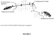
- the speed of the vehicle at each consecutive macro level segment may be captured. Using the speed at the macro level segment and the composite score the CRS may be computed using series of formulae as described in the following description referring to figure 5 .
- the trajectory of the vehicle A and the trajectory of the vehicle B may be generated using the GPS samples and the acceleration samples for the respective vehicles.
- a i (a x , ay, a z ) I
- X may be acceleration in the lateral direction
- Y may be acceleration in the longitudinal direction
- Z may be acceleration in the vertical direction of the traverse of the vehicle A and the vehicle B.
- points A1, A2 and A3 may indicate points along the traverse of the vehicle A, wherein A1 to A2 and A2 to A3 may indicate macro level segments.
- points B1, B2 and B3 may indicate macro level segment for the vehicle B.
- figure 5 shows micro level segments formed over the macro level segments for each vehicle. Also, possible point of crash may be seen from the figure 5 .
- Second score ⁇ a y > 0.3 g min a y g Ng
- Third score ⁇ a z > 0.3 g min a z g Ng
- all the weights may be determined by making judicious judgment about the driver's relative influence on each score.
- Table 1 EVENT RELATED SCORE DRIVER DEPENDANCY RISK RELEVANCE High acceleration Second score High Medium Hard brake Second score Medium High Cornering First score High Medium Swerving First score Medium Low Road roughness Third score Low Low Speeding beyond location based speed limit Third score High High
- the relative weights may be set as- Table 2 Weights Relevance Wsecond score HIGH Wfirst score MEDIUM Wthird score LOW
- v macro (v start +v end ) / 2.
- Vmacro (j) For j th macrotrip v macro may be denoted by Vmacro (j).
- MacVScore j min ⁇ 1, v macro (j)/ v limit ⁇ may be computed, where v limit may indicative of the speed limit for the location in which the crash has taken place.
- the composite score and the MacVScore j may be denoted on the macro level segment of the trajectory generated for the vehicles.
- a 2D trajectory may be generated for the vehicle A and the vehicle B as shown in the figure 5 using the GPS samples as follows-
- R e 6378100 m is earth's radius and all calculations and data captured may be in radian.
- the micro level segment score as MT may be computed.
- w i is indicative of the weights associated with the importance of the i th micro level segment with respect to the instance of the crash. That means, the micro level segment closer to the crash may get more weightage.
- w i 2 i k k + 1
- the CRS for each vehicle may be computed using the equation 10.
- the CRS computed for each vehicle may represent responsibility score of each vehicle involved in the crash. Value of the CRS may vary between 0 to 1, with 1 indicating full responsible for the crash and 0 indicating no responsibility. In simpler words higher score imply higher responsibility.
- the CRS may similarly be computed for the other vehicle involved in the crash by performing same steps as discussed earlier. Hence the CRS may assist a crash analyst to arrive at a conclusion which vehicle was at fault with respect to other vehicle based on the CRS.
- Some embodiments of the present disclosure allow analysis of the crash of the one or more vehicles based on minimal number of sensor data.
- Some embodiments of the present disclosure that allow responsibility analysis at each micro level as well as macro level segment of the trajectory of the vehicle traverse by facilitating plotting of the scores such as the at least one macro level score and the CRS at the macro level segments on the trajectory for clear understanding and analysis of the crash.
- Some embodiments of the present disclosure facilitate easy ascertainment of the responsibility of the vehicles at the crash.
- the order in which the method 600 is described is not intended to be construed as a limitation, and any number of the described method blocks can be combined in any order to implement the method 600 or alternate methods. Additionally, individual blocks may be deleted from the method 600 without departing from the spirit and scope of the disclosure described herein. Furthermore, the method can be implemented in any suitable hardware, software, firmware, or combination thereof. However, for ease of explanation, in the embodiments described below, the method 600 may be considered to be implemented in the above described system 102.
- the plurality of GPS samples associated with the vehicle at a predefined time interval may be received and subsequently stored in the data store 212.
- a trajectory may be by tracing the plurality of GPS samples.
- the trajectory may be segmented into one or more macro level segments and further into one or more micro level segments.
- the plurality of acceleration samples for at least one micro level segment may be received and subsequently stored in the data store 212.
- At block 610 at least one micro level segment score corresponding to the at least one micro level segment may be computed.
- At block 612 at least one macro level score corresponding to the at least one macro level segment may be computed.
- a crash responsibility score based upon the at least one macro level score may be determined and subsequently a crash analysis may be performed.
Landscapes
- Physics & Mathematics (AREA)
- General Physics & Mathematics (AREA)
- Chemical & Material Sciences (AREA)
- Analytical Chemistry (AREA)
- Engineering & Computer Science (AREA)
- Radar, Positioning & Navigation (AREA)
- Remote Sensing (AREA)
- Computer Networks & Wireless Communication (AREA)
- Traffic Control Systems (AREA)
Description
- The present disclosure described herein, in general, relates to systems and methods for crash analysis, more particularly ascertaining crash responsibility based on the crash analysis of one or more vehicles involved in a crash.
- Road accident is an unplanned event occurring suddenly, unexpectedly and inadvertently in an unforeseen circumstance. Rapid growth of population coupled with increased economic activities has favored tremendous growth of motor vehicles posing as one of primary factors responsible for the road accidents/crash. The highway network is accelerated at a fast rate and the safety of vehicular movements becomes a concern for everybody due to reporting of loss of lives and properties along with fatal injuries and periodical obstruction of traffic flow. National highways provide the efficient mobility and accessibility function. The road accidents/crashes are essentially caused by interactions of the vehicles, road users and roadway conditions. Each of these basic elements comprises a number of sub elements like pavement characteristics, geometric features, traffic characteristics, road user's behavior, vehicle design, driver's characteristics and environmental aspects.
- Today, numerous "black box" technologies exist to provide road accident investigators, insurance companies and legal counsel with significant information regarding a car accident. The black box technologies may include after-market solutions that may include GPS capabilities, video capture, and storage of crash data. Furthermore, the black box technologies are able to create 3D animated model of accident/crash for legal and insurance claim settlement purposes. Such existing solutions are mostly from representation purpose and not from an analysis point of view. Data recovered from devices/sensors present on the car in case of single car involved in the accident/crash or two cars involved in collision are subjected to study the nature of accident/crash. With advances in sensor technology it is possible to acquire data from moving car. Further, few tools for recreating trajectory of the car of 2D virtual recreation of the accident/crash exists, however are restricted to assist subjective analysis by human.
-
US 2010/174449 A1 describes a method of storing accident data for a vehicle, in which image data taken by a camera during driving is stored in real time, a weight value is set according to a measured impulse value to calculate a priority index and data is stored in a memory based on the priority index, thereby preventing initial accident-cause data from being deleted over time. Further, the documentKR 2010 0081706 A - However, the above mentioned systems does not provide a detailed analysis of a crash of one or more vehicles involved in the crash based on minimal number of sensor data. Also, these systems fails to assist a crash analyst to arrive at a conclusion which vehicle was at fault with respect to other vehicle during a crash.
- This summary is provided to introduce aspects related to systems and methods for performing crash analysis of one or more vehicles involved in a crash and the aspects are further described below in the detailed description. This summary is not intended to identify essential features of the claimed disclosure nor is it intended for use in determining or limiting the scope of the claimed disclosure.
- In one implementation, a method for performing crash analysis of one or more vehicles involved in a crash is disclosed. The method may comprise receiving a plurality of GPS samples associated with a vehicle at a predefined time interval. The method may further comprise generating a trajectory for the vehicle, wherein the trajectory is generated by tracing the plurality of GPS samples. Furthermore, the method may comprise segmenting the trajectory into one or more macro level segments, wherein each macro level segment is further segmented into one or more micro level segments. Furthermore, the method may comprise receiving a plurality of acceleration samples for at least one micro level segment of each macro level segment. In the next step the method may comprise computing at least one micro level segment score corresponding to at least one micro level segment. The at least one micro level segment score is computed based upon the plurality of acceleration samples. The method may further comprise computing at least one macro level score corresponding to at least one macro level segment, wherein the at least one macro level score is computed based upon one of the at least one micro level segment score and a reference speed of the vehicle, and wherein the reference speed is indicative of a speed measured corresponding to the at least one macro level segment and an adjacent macro level segment of the at least one macro level segment. Finally, the method may comprise determining a crash responsibility score based upon the at least one macro level score, wherein the crash responsibility score facilitates in performing crash analysis of the vehicle.
- In another implementation, a system for performing crash analysis of one or more vehicles involved in a crash is disclosed. The system may comprise a processor and a memory coupled to the processor, wherein the processor is capable of executing a plurality of modules stored in the memory, and wherein the plurality of module comprises a trajectory module, a scoring module, and a crash analysis module. The trajectory module may be configured to receive a plurality of GPS samples associated with a vehicle at a predefined time interval. The trajectory module may further be configured to generate a trajectory for the vehicle, wherein the trajectory is generated by tracing the plurality of GPS samples. Further, the trajectory module may further segment the trajectory into one or more macro level segments. Each macro level segment is further segmented into one or more micro level segments. The scoring module may be configured to receive a plurality of acceleration samples for at least one micro level segment of each macro level segment. The scoring module may further be configured to compute at least one micro level segment score corresponding to at least one micro level segment, wherein the at least one micro level segment score is computed based upon the plurality of acceleration samples and at least one macro level score corresponding to at least one macro level segment. Further, the at least one macro level score is computed based upon one of the at least one micro level segment score and a reference speed of the vehicle. The reference speed is indicative of a speed measured corresponding to the at least one macro level segment and an adjacent macro level segment of the at least one macro level segment. The crash analysis module may be configured to determine a crash responsibility score based upon the at least one macro level score. The crash responsibility score may further facilitates in performing crash analysis of the vehicle.
- In yet another implementation, a non-transitory computer readable medium embodying a program executable in a computing device for performing crash analysis of one or more vehicles involved in a crash is disclosed. The program may comprise a program code for receiving a plurality of GPS samples associated with a vehicle at a predefined time interval. The computer program may further comprise a program code for receiving a plurality of GPS samples associated with a vehicle at a predefined time interval. The computer program may further comprise a program code for segmenting the trajectory into one or more macro level segments, wherein each macro level segment is further segmented into one or more micro level segments. Furthermore, the program may comprise a program code for receiving a plurality of acceleration samples for at least one micro level segment of each macro level segment. The program may further comprise a program code for computing at least one micro level segment score corresponding to at least one micro level segment, wherein the at least one micro level segment score is computed based upon the plurality of acceleration samples and at least one macro level score corresponding to at least one macro level segment, wherein the at least one macro level score is computed based upon one of the at least one micro level segment score and a reference speed of the vehicle, and wherein the reference speed is indicative of a speed measured corresponding to the at least one macro level segment and an adjacent macro level segment of the at least one macro level segment. The program may further comprise a program code for determining a crash responsibility score based upon the at least one macro level score, wherein the crash responsibility score facilitates in performing crash analysis of the vehicle.
- The detailed description is described with reference to the accompanying figures. In the figures, the left-most digit(s) of a reference number identifies the figure in which the reference number first appears. The same numbers are used throughout the drawings to refer like features and components.
-
Figure 1 illustrates a network implementation of a system for crash analysis of one or more vehicles involved in a crash, in accordance with an embodiment of the present disclosure. -
Figure 2 illustrates the system, in accordance with an embodiment of the present disclosure. -
Figure 3 illustrates architecture of the system for crash analysis, in accordance with an embodiment of the present disclosure. -
Figure 4 illustrates Coordinate System for 3 axis accelerometer with respect to the vehicle, in accordance with an embodiment of the present disclosure. -
Figure 5 illustrates model based crash recreation for each vehicle. -
Figure 6 illustrates a method for the crash analysis of one or more vehicles involved in a crash, in accordance with an embodiment of the present disclosure. - Some embodiments of this disclosure, illustrating all its features, will now be discussed in detail. The words "comprising," "having," "containing," and "including," and other forms thereof, are intended to be equivalent in meaning and be open ended in that an item or items following any one of these words is not meant to be an exhaustive listing of such item or items, or meant to be limited to only the listed item or items. It must also be noted that the singular forms "a," "an," and "the" include plural references unless the context clearly dictates otherwise. Although any systems and methods similar or equivalent to those described herein can be used in the practice or testing of embodiments of the present disclosure, the exemplary, systems and methods are now described. The disclosed embodiments are merely exemplary of the disclosure, which may be embodied in various forms.
- Various modifications to the embodiment will be readily apparent to those skilled in the art and the generic principles herein may be applied to other embodiments. However, one of ordinary skill in the art will readily recognize that the present disclosure is not intended to be limited to the embodiments illustrated, but is to be accorded the widest scope consistent with the principles and features described herein.
- While aspects of the described system for crash analysis of one or more vehicles involved in a crash may be implemented in any number of different computing systems, environments, and/or configurations, the embodiments are described in the context of the following exemplary system.
- Although the present disclosure is explained considering that the
system 102 is implemented as a server, it may be understood that thesystem 102 may also be implemented in a variety of computing systems, such as a laptop computer, a desktop computer, a notebook, a workstation, a mainframe computer, a network server, and the like. In one implementation, thesystem 102 may be implemented in a cloud-based environment. It will be understood that thesystem 102 may be accessed by multiple users through one or more user devices 104-1, 104-2...104-N, collectively also referred to as auser device 104, or auser 104, hereinafter, or applications residing on theuser devices 104. Examples of theuser devices 104 may include, but are not limited to, a portable computer, a personal digital assistant, a handheld device, and a workstation. Theuser devices 104 are communicatively coupled to thesystem 102 through anetwork 106. - In one implementation, the
network 106 may be a wireless network, a wired network or a combination thereof. Thenetwork 106 can be implemented as one of the different types of networks, such as intranet, local area network (LAN), wide area network (WAN), the internet, and the like. Thenetwork 106 may either be a dedicated network or a shared network. The shared network represents an association of the different types of networks that use a variety of protocols, for example, Hypertext Transfer Protocol (HTTP), Transmission Control Protocol/Internet Protocol (TCP/IP), Wireless Application Protocol (WAP), and the like, to communicate with one another. Further thenetwork 106 may include a variety of network devices, including routers, bridges, servers, computing devices, storage devices, and the like. - Referring now to
Figure 2 , thesystem 102 is illustrated in accordance with an embodiment of the present disclosure. In one embodiment, thesystem 102 may include at least oneprocessor 202, an input/output (I/O)interface 204, and amemory 206. The at least oneprocessor 202 may be implemented as one or more microprocessors, microcomputers, microcontrollers, digital signal processors, central processing units, state machines, logic circuitries, and/or any devices that manipulate signals based on operational instructions. Among other capabilities, the at least oneprocessor 202 is configured to fetch and execute computer-readable instructions stored in thememory 206. - The I/
O interface 204 may include a variety of software and hardware interfaces, for example, a web interface, a graphical user interface, and the like. The I/O interface 204 may allow thesystem 102 to interact with a user directly or through theuser device 104. Further, the I/O interface 204 may enable thesystem 102 to communicate with other computing devices, such as web servers and external data servers (not shown). The I/O interface 204 can facilitate multiple communications within a wide variety of networks and protocol types, including wired networks, for example, LAN, cable, etc., and wireless networks, such as WLAN, cellular, or satellite. The I/O interface 204 may include one or more ports for connecting a number of devices to one another or to another server. - The
memory 206 may include any computer-readable medium known in the art including, for example, volatile memory, such as static random access memory (SRAM) and dynamic random access memory (DRAM), and/or non-volatile memory, such as read only memory (ROM), erasable programmable ROM, flash memories, hard disks, optical disks, and magnetic tapes. Thememory 206 may includemodules 208 anddata 210. - The
modules 208 include routines, programs, objects, components, data structures, etc., which perform particular tasks, functions or implement particular abstract data types. In one implementation, themodules 208 may include atrajectory module 216, ascoring module 218, acrash analysis module 220 andother module 222. Theother module 222 may include programs or coded instructions that supplement applications and functions of thesystem 102. - The
data 210, amongst other things, serves as a repository for storing data processed, received, and generated by one or more of themodules 208. Thedata 210 may also include adata store 212 andother data 214. Theother data 214 may include data generated as a result of the execution of one or more modules in the other module 228. - In one implementation, at first, a user may use the
user device 104 to access thesystem 102 via the I/O interface 204. The user may register themselves using the I/O interface 204 in order to use thesystem 102. The working of thesystem 102 using the plurality ofmodules 208 along with other components is explained in detail referring tofigure 3 as explained below. - Referring now to
figure 3 , in an embodiment,architecture 300 of the system for crash analysis involved in crash is shown. Thearchitecture 300 may comprise of adata store 212, atrajectory module 216, ascoring module 218 and acrash analysis module 220. Thetrajectory module 216 may be configured to receive data samples from sensors integrated with one or more vehicles. In an embodiment, the system and method may be explained by using minimal number of sensors to receive data samples indicative of crash data associated with the one or more vehicles involved in the crash. The crash data may further comprise data related to speed, location, and acceleration of the vehicle at a particular location during traverse of the vehicle. The data samples i.e. crash data received from the sensors may be stored in thedata store 212. - In the embodiment a GPS sensor may be adapted to sense the speed and location of the one or more vehicles. Furthermore, a 3 axis accelerometer may also be adapted to sense the acceleration of the one or more moving vehicles about three axes. In an aspect of the present disclosure, the basic purpose of the crash analysis disclosed herein is to make use of minimum number of sensors for the crash analysis. As shown in the
figure 3 , thedata store 212 may be adapted to store the GPS samples and the acceleration samples received from the GPS sensor and the 3 axis accelerometer respectively associated with the vehicle. Upon receiving the data samples from the GPS sensor and the 3 axis accelerometer by thedata store 212, thetrajectory module 220 may be configured to generate a trajectory of the one or more vehicles, wherein thetrajectory module 216 may be connected to thedata store 212. The trajectory generated may be based on the GPS data samples. Furthermore, thetrajectory module 216 may be configured to segment the trajectory into one or more macro level segments. Further, the trajectory module may be configured to segment the one or more macro level segment into one or more micro level segments. In next step, thescoring module 218 may be configured to compute at least one micro level score and at least one macro level score. In the final stage, thecrash analysis module 220 may be configured to compute crash responsibility score based on at least one of the micro level score and the macro level score, based on which the crash analysis may be performed to identify which vehicle was at fault or responsible for the crash. It is important to note that, crash may be between two or more vehicles or only single vehicle may be involved wherein the said single vehicle may crash onto a stationary object. - In an embodiment, a series of scores for each vehicle may be generated from few minutes before the crash till the actual crash time. Hence the series of scores may help visualize driving behavior for each vehicle involved in the crash chronologically till the actual crash. Further, the present disclosure may adapt weighted moving average (WMA) having specific meaning of weights that increase in arithmetical progression. The WMA may help in accommodate a fact that bad driving closer to the crash time may have more responsibility for the crash. Moreover, the system and method may be enabled to analyze driving behavior in a decoupled manner so as to achieve different scores for lateral, longitudinal and vertical acceleration profile of the one or more vehicles. Additionally, there may exist three cases in case of the crash such as a) generic situation in which two cars/vehicles are colliding with each other, b) single car/vehicle breakdown, and c) Single car/vehicle or hitting another stationary object. Taking these cases into account the score named a Crash Responsibility Score (CRS) may be computed to ascertain the responsibility. The computation of the CRS may be further explained in detail as discussed in following description.
- In an embodiment, the
trajectory module 220 may be configured to generate the trajectory for the one or more vehicles involved in the crash. In the first step, based on the GPS samples received at theData store 212, longitudinal and latitudinal readings associated with the location of the vehicle may be captured for a predefined time interval. Further, simultaneously the acceleration samples may also be captured for the same time interval. In other word, between two consecutive GPS samples, number of acceleration samples may exist which may be captured by the GPS sensor and stored in thedata store 212.. For example, (ali, a2i, a3i... ani) be the acceleration samples, where 'a' indicates 3-axis acceleration vector (X, Y, Z) and index 'i' corresponds to ith sample of the GPS sample. The three axis acceleration may be explained in detail by referringfigure 4 . - Referring to the
figure 4 is a co-ordinate system with respect to the vehicle. As shown in thefigure 4 , X-axis may indicate a lateral acceleration, Y-axis may indicate a longitudinal acceleration, and Z-axis may indicate a vertical acceleration the vehicle. In an embodiment, the GPS sample and the acceleration sample may be captured few minutes before the actual crash. In next step, based on the acceleration samples at three axes and the GPS samples, a composite score at the at least one micro level segment may be computed. The composite score may indicative of road quality, vehicle state & driving pattern associated with the vehicle. Further, based on the GPS samples, the speed of the vehicle at each consecutive macro level segment may be captured. Using the speed at the macro level segment and the composite score the CRS may be computed using series of formulae as described in the following description referring tofigure 5 . - Referring to the
figure 5 , the trajectory of the vehicle A and the trajectory of the vehicle B may be generated using the GPS samples and the acceleration samples for the respective vehicles. In an embodiment, let ai = (ax, ay, az)I, where X may be acceleration in the lateral direction, Y may be acceleration in the longitudinal direction and Z may be acceleration in the vertical direction of the traverse of the vehicle A and the vehicle B. further, as shown in thefigure 5 , points A1, A2 and A3 may indicate points along the traverse of the vehicle A, wherein A1 to A2 and A2 to A3 may indicate macro level segments. Similarly, points B1, B2 and B3 may indicate macro level segment for the vehicle B. Furthermore,figure 5 shows micro level segments formed over the macro level segments for each vehicle. Also, possible point of crash may be seen from thefigure 5 . Hence according to the embodiment, for N accelerometer samples in the micro level segment e.g. at 20 Hz sampling, N=20, various score may be computed as follows-


- Using
equations 
- In an embodiment, all the weights may be determined by making judicious judgment about the driver's relative influence on each score. For example, the common understanding is represented in the following table 1.
Table 1 EVENT RELATED SCORE DRIVER DEPENDANCY RISK RELEVANCE High acceleration Second score High Medium Hard brake Second score Medium High Cornering First score High Medium Swerving First score Medium Low Road roughness Third score Low Low Speeding beyond location based speed limit Third score High High - Thus, analyzing the table 1, the relative weights may be set as-
Table 2 Weights Relevance Wsecond score HIGH Wfirst score MEDIUM Wthird score LOW - In next step, for each macro level segment, there may exists two speed readings captured from the GPS sensor i.e. at start and end of each micro level segment, and may be denoted by macro level segment speed by vmacro = (vstart+vend) / 2. For jth macrotrip vmacro may be denoted by Vmacro(j). Hence, for the macro level segment j a speed score denoted by MacVScorej = min{ 1, vmacro(j)/ vlimit} may be computed, where vlimit may indicative of the speed limit for the location in which the crash has taken place. The composite score and the MacVScorej may be denoted on the macro level segment of the trajectory generated for the vehicles. A 2D trajectory may be generated for the vehicle A and the vehicle B as shown in the
figure 5 using the GPS samples as follows- - Initial location may be assumed to be (0, 0) i.e. x 0 = 0, y0 = 0. Subsequent (x, y) points may be calculated as


- Where, R e = 6378100 m is earth's radius and all calculations and data captured may be in radian.
- Using the GPS samples, for the vehicle A denoted by lati (1), loni (1) and the vehicle B may be denoted by lati (2), loni (2). Only initial location may be calculated differently using the GPS samples from both the vehicles to determine initial position. Then next locations may be determined recursively.


- Thus subsequent points:


- Hence, on the XY plane representative plot may be generated as given in the
figure 5 using (x, y) and (x ,y ) with the macro level segment and the micro level segment scores for each vehicle. Hence given two vehicles crash data, a graphic representation like thefigure 5 may be generated. - Now, in the next step, to compute the CRS for each vehicle, i macro level segment, which means k microtrips, where k= integer (k/FsGPS), FsGPS= sampling rate of the GPS sensor, and further k micro level segment may be computed before the instance of the crash. Typically, k = 15-300 may be considered. From the data captured, the micro level segment score as MT may be computed. Based on the scores the CRS_acc may be computed from acceleration data (CRS _acc ) for each vehicle for trip T containing k micro level segments i.e. trip duration T= k/Fs, where Fs is sampling rate of the 3 axis accelerometer.

- In the equation (6), wi is indicative of the weights associated with the importance of the ith micro level segment with respect to the instance of the crash. That means, the micro level segment closer to the crash may get more weightage.

- Then from velocity based scores MacVScore, the CRS from acceleration data (CRS_ speed ), further referred to as a second macro level score for each vehicle involved in the crash by using equation (8) may be computed.

- Where, wmi is the weights associated with the importance of i-th macro level segment with respect to the instance of the crash. That means, the macro levels segment closer to the crash may get more weightage.

- Using CRS_acc and CRS_speed, the CRS may be computed as

- Where, wacc + wspeed = 1,wspeedwacc > 0 may be specified by configuration settings at server side.
- In an aspect of the present disclosure, the CRS for each vehicle may be computed using the equation 10. The CRS computed for each vehicle may represent responsibility score of each vehicle involved in the crash. Value of the CRS may vary between 0 to 1, with 1 indicating full responsible for the crash and 0 indicating no responsibility. In simpler words higher score imply higher responsibility. Further, the CRS may similarly be computed for the other vehicle involved in the crash by performing same steps as discussed earlier. Hence the CRS may assist a crash analyst to arrive at a conclusion which vehicle was at fault with respect to other vehicle based on the CRS.
- Exemplary embodiments discussed above may provide certain advantages. Though not required to practice aspects of the disclosure, these advantages may include those provided by the following features.
- Some embodiments of the present disclosure allow analysis of the crash of the one or more vehicles based on minimal number of sensor data.
- Some embodiments of the present disclosure that allow responsibility analysis at each micro level as well as macro level segment of the trajectory of the vehicle traverse by facilitating plotting of the scores such as the at least one macro level score and the CRS at the macro level segments on the trajectory for clear understanding and analysis of the crash.
- Some embodiments of the present disclosure facilitate easy ascertainment of the responsibility of the vehicles at the crash.
- The order in which the
method 600 is described is not intended to be construed as a limitation, and any number of the described method blocks can be combined in any order to implement themethod 600 or alternate methods. Additionally, individual blocks may be deleted from themethod 600 without departing from the spirit and scope of the disclosure described herein. Furthermore, the method can be implemented in any suitable hardware, software, firmware, or combination thereof. However, for ease of explanation, in the embodiments described below, themethod 600 may be considered to be implemented in the above describedsystem 102. - At
block 602, the plurality of GPS samples associated with the vehicle at a predefined time interval may be received and subsequently stored in thedata store 212. - At
block 604, a trajectory may be by tracing the plurality of GPS samples. - At
block 606, upon generation of the trajectory, the trajectory may be segmented into one or more macro level segments and further into one or more micro level segments. - At
block 608, the plurality of acceleration samples for at least one micro level segment may be received and subsequently stored in thedata store 212. - At
block 610, at least one micro level segment score corresponding to the at least one micro level segment may be computed. - At
block 612, at least one macro level score corresponding to the at least one macro level segment may be computed. - At
block 614, a crash responsibility score based upon the at least one macro level score may be determined and subsequently a crash analysis may be performed. - Although implementations for methods and systems for crash analysis of one or more vehicles involved in a crash have been described in language specific to structural features and/or methods, it is to be understood that the appended claims are not necessarily limited to the specific features or methods described.
Claims (8)
- A method for performing crash analysis of one or more vehicles involved in a crash, the method comprising:receiving a plurality of GPS samples associated with a vehicle at a predefined time interval;generating a trajectory for the vehicle, wherein the trajectory is generated by tracing the plurality of GPS samples;segmenting the trajectory into one or more macro level segments,
wherein each macro level segment is further segmented into one or more micro level segments;receiving a plurality of acceleration samples for at least one micro level segment of each macro level segment;computingat least one micro level segment score corresponding to at least one micro level segment, wherein the at least one micro level segment score is computed based upon the plurality of acceleration samples, andat least one macro level score corresponding to at least one macro level segment, wherein the at least one macro level score is computed based upon one of the at least one micro level segment score and a reference speed of the vehicle, and wherein the reference speed is indicative of a speed measured corresponding to the at least one macro level segment and an adjacent macro level segment of the at least one macro level segment; anddetermining a crash responsibility score based upon the at least one macro level score, wherein the crash responsibility score facilitates in performing crash analysis of the vehicle. - The method of claim 1, wherein the at least one micro level segment score comprises at least one of a first score, a second score and a third score, and wherein the first score is indicative of longitudinal acceleration of the vehicle, and wherein the second score is indicative of lateral acceleration of the vehicle, and wherein the third score is indicative of vertical acceleration of the vehicle.
- The method of claim 2, wherein the at least one macro level score is computed based upon summation of the first score, the second score and the third score.
- The method of claim 1, wherein the plurality of GPS samples and the plurality acceleration samples are received from a GPS sensor and a 3 axis accelerometer sensor associated with the vehicle.
- The method of claim 1, wherein the at least one micro level score, the at least one macro level score and the crash responsibility score are displayed on the trajectory.
- The method of claim 1, wherein the crash responsibility score is having a value within a range of 0 to 1, wherein the value 0 indicates no responsibility and the value 1 indicates full responsibility of the vehicle in the crash.
- A system (102) for performing crash analysis of one or more vehicles involved in a crash, the system comprising:a processor (202); anda memory (206) coupled to the processor (202), wherein the processor (202)_is capable of executing a plurality of modules (208) stored in the memory (206), and wherein the plurality of modules (208) comprising:a trajectory module (216) configured toreceive a plurality of GPS samples associated with a vehicle at a predefined time interval;generate a trajectory for the vehicle, wherein the trajectory is generated by tracing the plurality of GPS samples; andsegment the trajectory into one or more macro level segments,
wherein each macro level segment is further segmented into one or more micro level segments;a scoring module (218) configured to
receive a plurality of acceleration samples for at least one micro level segment of each macro level segment; andcomputeat least one micro level segment score corresponding to at least one micro level segment, wherein the at least one micro level segment score is computed based upon the plurality of acceleration samples, andat least one macro level score corresponding to at least one macro level segment, wherein the at least one macro level score is computed based upon one of the at least one micro level segment score and a reference speed of the vehicle, and wherein the reference speed is indicative of a speed measured corresponding to the at least one macro level segment and an adjacent macro level segment of the at least one macro level segment; anda crash analysis module (220) configured to
determine a crash responsibility score based upon the at least one macro level score, wherein the crash responsibility score facilitates in performing crash analysis of the vehicle. - A non-transitory computer readable medium embodying a program executable in a computing device for crash analysis of one or more vehicles involved in a crash, the program comprising:a program code for receiving a plurality of GPS samples associated with a vehicle at a predefined time interval;a program code for receiving a plurality of GPS samples associated with a vehicle at a predefined time interval;a program code for segmenting the trajectory into one or more macro level segments, wherein each macro level segment is further segmented into one or more micro level segments;a program code for receiving a plurality of acceleration samples for at least one micro level segment of each macro level segment;a program code for computingat least one micro level segment score corresponding to at least one micro level segment, wherein the at least one micro level segment score is computed based upon the plurality of acceleration samples, andat least one macro level score corresponding to at least one macro level segment, wherein the at least one macro level score is computed based upon one of the at least one micro level segment score and a reference speed of the vehicle, and wherein the reference speed is indicative of a speed measured corresponding to the at least one macro level segment and an adjacent macro level segment of the at least one macro level segment; anda program code for determining a crash responsibility score based upon the at least one macro level score, wherein the crash responsibility score facilitates in performing crash analysis of the vehicle.
Applications Claiming Priority (1)
| Application Number | Priority Date | Filing Date | Title |
|---|---|---|---|
| IN3331MU2014 | 2014-10-18 |
Publications (2)
| Publication Number | Publication Date |
|---|---|
| EP3009990A1 EP3009990A1 (en) | 2016-04-20 |
| EP3009990B1 true EP3009990B1 (en) | 2017-11-22 |
Family
ID=52807550
Family Applications (1)
| Application Number | Title | Priority Date | Filing Date |
|---|---|---|---|
| EP15159226.8A Active EP3009990B1 (en) | 2014-10-18 | 2015-03-16 | Method and system for performing crash analysis of one or more vehicles |
Country Status (2)
| Country | Link |
|---|---|
| US (1) | US9665995B2 (en) |
| EP (1) | EP3009990B1 (en) |
Families Citing this family (5)
| Publication number | Priority date | Publication date | Assignee | Title |
|---|---|---|---|---|
| EP3009990B1 (en) * | 2014-10-18 | 2017-11-22 | Tata Consultancy Services Limited | Method and system for performing crash analysis of one or more vehicles |
| WO2017185114A1 (en) | 2016-04-27 | 2017-11-02 | Farmdok Gmbh | Method for detecting agricultural field work performed by a vehicle |
| WO2018002386A1 (en) * | 2016-06-30 | 2018-01-04 | Dirección General De Tráfico | Method for determining an index that allows the establishment and evaluation of policies for monitoring speed on roads in a territory |
| CN106558219B (en) * | 2016-10-20 | 2020-05-12 | 深圳市元征科技股份有限公司 | Vehicle track prediction method and device |
| CN110160541B (en) * | 2018-08-06 | 2022-02-22 | 腾讯大地通途(北京)科技有限公司 | Method and device for reconstructing motion trail, storage medium and electronic device |
Family Cites Families (21)
| Publication number | Priority date | Publication date | Assignee | Title |
|---|---|---|---|---|
| US7359821B1 (en) * | 2002-06-11 | 2008-04-15 | Injury Sciences Llc | Methods and apparatus for using black box data to analyze vehicular accidents |
| US7809586B2 (en) * | 2002-11-27 | 2010-10-05 | Computer Sciences Corporation | Computerized method and system for estimating an effect on liability using a comparison of the actual speed of a vehicle in an accident and time and distance traveled by the vehicles in a merging vehicle accident |
| DE102004039286A1 (en) * | 2003-12-31 | 2005-08-04 | Su, Hasan | System for evaluation of motor vehicle operating risk, comprises a vehicle onboard system which records sensor driving data and evaluates it using a computer observation module prior to transmitting it to a central unit |
| WO2006131926A2 (en) * | 2005-06-09 | 2006-12-14 | Drive Diagnostics Ltd. | System and method for displaying a driving profile |
| KR20070041279A (en) * | 2005-10-14 | 2007-04-18 | 여창동 | Black box system for vehicle |
| US9836716B2 (en) * | 2006-05-09 | 2017-12-05 | Lytx, Inc. | System and method for reducing driving risk with hindsight |
| TW200828193A (en) * | 2006-12-29 | 2008-07-01 | Inventec Appliances Corp | Method for dealing with a traffic accident and appratus thereof |
| KR100831667B1 (en) * | 2007-06-21 | 2008-05-22 | 주식회사 피엘케이 테크놀로지 | Method of storing accident data for a vehicle |
| WO2009133429A1 (en) * | 2008-04-30 | 2009-11-05 | Sabanci Universitesi | Traffic accident analysis sytem |
| JP5561847B2 (en) * | 2008-06-19 | 2014-07-30 | ローム株式会社 | Drive recorder |
| KR101049183B1 (en) * | 2009-01-07 | 2011-07-14 | 아진산업(주) | Car accident record system |
| US9401178B2 (en) * | 2010-08-26 | 2016-07-26 | Blast Motion Inc. | Event analysis system |
| US8749350B2 (en) * | 2010-12-10 | 2014-06-10 | General Motors Llc | Method of processing vehicle crash data |
| CN102034013B (en) | 2010-12-30 | 2012-10-10 | 长安大学 | Analysis, computation and simulative reappearance computer system for automobile oblique collision accident |
| IT1403839B1 (en) * | 2011-02-09 | 2013-11-08 | Infomobility It S P A | SAFETY DEVICE FOR VEHICLE. |
| US8762044B2 (en) * | 2011-07-13 | 2014-06-24 | Dynamic Research, Inc. | System and method for testing crash avoidance technologies |
| US8620518B2 (en) * | 2011-07-26 | 2013-12-31 | United Parcel Service Of America, Inc. | Systems and methods for accident reconstruction |
| US20140195071A1 (en) * | 2012-03-14 | 2014-07-10 | Zonar Systems, Inc. | Emergency event based vehicle data logging |
| US9852636B2 (en) * | 2012-05-18 | 2017-12-26 | International Business Machines Corproation | Traffic event data source identification, data collection and data storage |
| US8799034B1 (en) * | 2013-03-08 | 2014-08-05 | Allstate University Company | Automated accident detection, fault attribution, and claims processing |
| EP3009990B1 (en) * | 2014-10-18 | 2017-11-22 | Tata Consultancy Services Limited | Method and system for performing crash analysis of one or more vehicles |
-
2015
- 2015-03-16 EP EP15159226.8A patent/EP3009990B1/en active Active
- 2015-03-19 US US14/662,338 patent/US9665995B2/en active Active
Non-Patent Citations (1)
| Title |
|---|
| None * |
Also Published As
| Publication number | Publication date |
|---|---|
| US9665995B2 (en) | 2017-05-30 |
| US20160110931A1 (en) | 2016-04-21 |
| EP3009990A1 (en) | 2016-04-20 |
Similar Documents
| Publication | Publication Date | Title |
|---|---|---|
| EP3009990B1 (en) | Method and system for performing crash analysis of one or more vehicles | |
| CN109032102B (en) | Unmanned vehicle testing method, device, equipment and storage medium | |
| DE102017101466A1 (en) | TRACKING OBJECTS IN A DYNAMIC ENVIRONMENT FOR IMPROVED LOCALIZATION | |
| KR101689805B1 (en) | Apparatus and method for reconstructing scene of traffic accident using OBD, GPS and image information of vehicle blackbox | |
| CN111177887A (en) | Method and device for constructing simulation track data based on real driving scene | |
| Seppi et al. | Repeatability of a dynamic rollover test system | |
| CN102622885A (en) | Method and device for detecting traffic incidents | |
| DE102017118078A1 (en) | Localization device for a motor vehicle, driver assistance device, motor vehicle and method for locating a motor vehicle | |
| DE102018222169A1 (en) | On-board visual determination of kinematic parameters of a rail vehicle | |
| Gobbi et al. | The effect of mass properties on road accident reconstruction | |
| CN111967451B (en) | Road congestion detection method and device | |
| Chen et al. | Speed distribution prediction of freight vehicles on mountainous freeway using deep learning methods | |
| Ambros et al. | Proactive assessment of road curve safety using floating car data: An exploratory study | |
| EP2966476B1 (en) | A system and method for determining speed of a vehicle based on gps speed | |
| CN112432643A (en) | Driving data generation method and device, electronic equipment and storage medium | |
| CN113640760B (en) | Radar discovery probability evaluation method and equipment based on air situation data | |
| CN116304986A (en) | Vehicle event fusion method, device, equipment and readable storage medium | |
| CN116301464A (en) | Method and device for displaying digital twin information of road and terminal equipment | |
| CN112729862B (en) | Unmanned driving behavior safety assessment method and device and electronic equipment | |
| DE102021120968A1 (en) | VEHICLE SENSOR OPERATION | |
| Xu et al. | Novel fast safety assessment method for the buffer section of maintenance work zone | |
| Nishizaki et al. | Development of a method for marine accident analysis with bridge simulator | |
| DE102018125880B4 (en) | System, method and computer-readable memory for (online) monitoring the operation of at least one vehicle | |
| Wang et al. | A crowdsourcing-based road anomaly classification system | |
| Dang et al. | Building safety road maps based on difference of judgment of road users by their Smartphone |
Legal Events
| Date | Code | Title | Description |
|---|---|---|---|
| PUAI | Public reference made under article 153(3) epc to a published international application that has entered the european phase |
Free format text: ORIGINAL CODE: 0009012 |
|
| AK | Designated contracting states |
Kind code of ref document: A1 Designated state(s): AL AT BE BG CH CY CZ DE DK EE ES FI FR GB GR HR HU IE IS IT LI LT LU LV MC MK MT NL NO PL PT RO RS SE SI SK SM TR |
|
| AX | Request for extension of the european patent |
Extension state: BA ME |
|
| 17P | Request for examination filed |
Effective date: 20161020 |
|
| RBV | Designated contracting states (corrected) |
Designated state(s): AL AT BE BG CH CY CZ DE DK EE ES FI FR GB GR HR HU IE IS IT LI LT LU LV MC MK MT NL NO PL PT RO RS SE SI SK SM TR |
|
| GRAP | Despatch of communication of intention to grant a patent |
Free format text: ORIGINAL CODE: EPIDOSNIGR1 |
|
| RIC1 | Information provided on ipc code assigned before grant |
Ipc: G08G 1/00 20060101ALI20170512BHEP Ipc: B60R 21/0132 20060101ALN20170512BHEP Ipc: G06Q 30/02 20120101ALI20170512BHEP Ipc: G07C 5/00 20060101ALI20170512BHEP Ipc: B62D 41/00 20060101ALI20170512BHEP Ipc: G07C 5/08 20060101AFI20170512BHEP Ipc: G01D 9/00 20060101ALI20170512BHEP Ipc: B60R 21/00 20060101ALN20170512BHEP Ipc: G08G 1/0968 20060101ALI20170512BHEP Ipc: H04N 5/225 20060101ALI20170512BHEP |
|
| INTG | Intention to grant announced |
Effective date: 20170606 |
|
| GRAS | Grant fee paid |
Free format text: ORIGINAL CODE: EPIDOSNIGR3 |
|
| GRAA | (expected) grant |
Free format text: ORIGINAL CODE: 0009210 |
|
| AK | Designated contracting states |
Kind code of ref document: B1 Designated state(s): AL AT BE BG CH CY CZ DE DK EE ES FI FR GB GR HR HU IE IS IT LI LT LU LV MC MK MT NL NO PL PT RO RS SE SI SK SM TR |
|
| REG | Reference to a national code |
Ref country code: GB Ref legal event code: FG4D |
|
| REG | Reference to a national code |
Ref country code: CH Ref legal event code: EP |
|
| REG | Reference to a national code |
Ref country code: IE Ref legal event code: FG4D |
|
| REG | Reference to a national code |
Ref country code: AT Ref legal event code: REF Ref document number: 949069 Country of ref document: AT Kind code of ref document: T Effective date: 20171215 |
|
| REG | Reference to a national code |
Ref country code: DE Ref legal event code: R096 Ref document number: 602015006099 Country of ref document: DE |
|
| REG | Reference to a national code |
Ref country code: NL Ref legal event code: MP Effective date: 20171122 |
|
| REG | Reference to a national code |
Ref country code: LT Ref legal event code: MG4D |
|
| REG | Reference to a national code |
Ref country code: AT Ref legal event code: MK05 Ref document number: 949069 Country of ref document: AT Kind code of ref document: T Effective date: 20171122 |
|
| PG25 | Lapsed in a contracting state [announced via postgrant information from national office to epo] |
Ref country code: FI Free format text: LAPSE BECAUSE OF FAILURE TO SUBMIT A TRANSLATION OF THE DESCRIPTION OR TO PAY THE FEE WITHIN THE PRESCRIBED TIME-LIMIT Effective date: 20171122 Ref country code: SE Free format text: LAPSE BECAUSE OF FAILURE TO SUBMIT A TRANSLATION OF THE DESCRIPTION OR TO PAY THE FEE WITHIN THE PRESCRIBED TIME-LIMIT Effective date: 20171122 Ref country code: LT Free format text: LAPSE BECAUSE OF FAILURE TO SUBMIT A TRANSLATION OF THE DESCRIPTION OR TO PAY THE FEE WITHIN THE PRESCRIBED TIME-LIMIT Effective date: 20171122 Ref country code: NL Free format text: LAPSE BECAUSE OF FAILURE TO SUBMIT A TRANSLATION OF THE DESCRIPTION OR TO PAY THE FEE WITHIN THE PRESCRIBED TIME-LIMIT Effective date: 20171122 Ref country code: NO Free format text: LAPSE BECAUSE OF FAILURE TO SUBMIT A TRANSLATION OF THE DESCRIPTION OR TO PAY THE FEE WITHIN THE PRESCRIBED TIME-LIMIT Effective date: 20180222 Ref country code: ES Free format text: LAPSE BECAUSE OF FAILURE TO SUBMIT A TRANSLATION OF THE DESCRIPTION OR TO PAY THE FEE WITHIN THE PRESCRIBED TIME-LIMIT Effective date: 20171122 |
|
| PG25 | Lapsed in a contracting state [announced via postgrant information from national office to epo] |
Ref country code: RS Free format text: LAPSE BECAUSE OF FAILURE TO SUBMIT A TRANSLATION OF THE DESCRIPTION OR TO PAY THE FEE WITHIN THE PRESCRIBED TIME-LIMIT Effective date: 20171122 Ref country code: GR Free format text: LAPSE BECAUSE OF FAILURE TO SUBMIT A TRANSLATION OF THE DESCRIPTION OR TO PAY THE FEE WITHIN THE PRESCRIBED TIME-LIMIT Effective date: 20180223 Ref country code: BG Free format text: LAPSE BECAUSE OF FAILURE TO SUBMIT A TRANSLATION OF THE DESCRIPTION OR TO PAY THE FEE WITHIN THE PRESCRIBED TIME-LIMIT Effective date: 20180222 Ref country code: AT Free format text: LAPSE BECAUSE OF FAILURE TO SUBMIT A TRANSLATION OF THE DESCRIPTION OR TO PAY THE FEE WITHIN THE PRESCRIBED TIME-LIMIT Effective date: 20171122 Ref country code: HR Free format text: LAPSE BECAUSE OF FAILURE TO SUBMIT A TRANSLATION OF THE DESCRIPTION OR TO PAY THE FEE WITHIN THE PRESCRIBED TIME-LIMIT Effective date: 20171122 Ref country code: LV Free format text: LAPSE BECAUSE OF FAILURE TO SUBMIT A TRANSLATION OF THE DESCRIPTION OR TO PAY THE FEE WITHIN THE PRESCRIBED TIME-LIMIT Effective date: 20171122 |
|
| REG | Reference to a national code |
Ref country code: FR Ref legal event code: PLFP Year of fee payment: 4 |
|
| PG25 | Lapsed in a contracting state [announced via postgrant information from national office to epo] |
Ref country code: CY Free format text: LAPSE BECAUSE OF FAILURE TO SUBMIT A TRANSLATION OF THE DESCRIPTION OR TO PAY THE FEE WITHIN THE PRESCRIBED TIME-LIMIT Effective date: 20171122 Ref country code: DK Free format text: LAPSE BECAUSE OF FAILURE TO SUBMIT A TRANSLATION OF THE DESCRIPTION OR TO PAY THE FEE WITHIN THE PRESCRIBED TIME-LIMIT Effective date: 20171122 Ref country code: SK Free format text: LAPSE BECAUSE OF FAILURE TO SUBMIT A TRANSLATION OF THE DESCRIPTION OR TO PAY THE FEE WITHIN THE PRESCRIBED TIME-LIMIT Effective date: 20171122 Ref country code: CZ Free format text: LAPSE BECAUSE OF FAILURE TO SUBMIT A TRANSLATION OF THE DESCRIPTION OR TO PAY THE FEE WITHIN THE PRESCRIBED TIME-LIMIT Effective date: 20171122 Ref country code: EE Free format text: LAPSE BECAUSE OF FAILURE TO SUBMIT A TRANSLATION OF THE DESCRIPTION OR TO PAY THE FEE WITHIN THE PRESCRIBED TIME-LIMIT Effective date: 20171122 |
|
| REG | Reference to a national code |
Ref country code: DE Ref legal event code: R097 Ref document number: 602015006099 Country of ref document: DE |
|
| PG25 | Lapsed in a contracting state [announced via postgrant information from national office to epo] |
Ref country code: PL Free format text: LAPSE BECAUSE OF FAILURE TO SUBMIT A TRANSLATION OF THE DESCRIPTION OR TO PAY THE FEE WITHIN THE PRESCRIBED TIME-LIMIT Effective date: 20171122 Ref country code: RO Free format text: LAPSE BECAUSE OF FAILURE TO SUBMIT A TRANSLATION OF THE DESCRIPTION OR TO PAY THE FEE WITHIN THE PRESCRIBED TIME-LIMIT Effective date: 20171122 Ref country code: SM Free format text: LAPSE BECAUSE OF FAILURE TO SUBMIT A TRANSLATION OF THE DESCRIPTION OR TO PAY THE FEE WITHIN THE PRESCRIBED TIME-LIMIT Effective date: 20171122 Ref country code: IT Free format text: LAPSE BECAUSE OF FAILURE TO SUBMIT A TRANSLATION OF THE DESCRIPTION OR TO PAY THE FEE WITHIN THE PRESCRIBED TIME-LIMIT Effective date: 20171122 |
|
| PLBE | No opposition filed within time limit |
Free format text: ORIGINAL CODE: 0009261 |
|
| STAA | Information on the status of an ep patent application or granted ep patent |
Free format text: STATUS: NO OPPOSITION FILED WITHIN TIME LIMIT |
|
| 26N | No opposition filed |
Effective date: 20180823 |
|
| PG25 | Lapsed in a contracting state [announced via postgrant information from national office to epo] |
Ref country code: SI Free format text: LAPSE BECAUSE OF FAILURE TO SUBMIT A TRANSLATION OF THE DESCRIPTION OR TO PAY THE FEE WITHIN THE PRESCRIBED TIME-LIMIT Effective date: 20171122 Ref country code: MC Free format text: LAPSE BECAUSE OF FAILURE TO SUBMIT A TRANSLATION OF THE DESCRIPTION OR TO PAY THE FEE WITHIN THE PRESCRIBED TIME-LIMIT Effective date: 20171122 |
|
| REG | Reference to a national code |
Ref country code: BE Ref legal event code: MM Effective date: 20180331 |
|
| REG | Reference to a national code |
Ref country code: IE Ref legal event code: MM4A |
|
| PG25 | Lapsed in a contracting state [announced via postgrant information from national office to epo] |
Ref country code: LU Free format text: LAPSE BECAUSE OF NON-PAYMENT OF DUE FEES Effective date: 20180316 |
|
| PG25 | Lapsed in a contracting state [announced via postgrant information from national office to epo] |
Ref country code: IE Free format text: LAPSE BECAUSE OF NON-PAYMENT OF DUE FEES Effective date: 20180316 |
|
| PG25 | Lapsed in a contracting state [announced via postgrant information from national office to epo] |
Ref country code: BE Free format text: LAPSE BECAUSE OF NON-PAYMENT OF DUE FEES Effective date: 20180331 |
|
| PG25 | Lapsed in a contracting state [announced via postgrant information from national office to epo] |
Ref country code: MT Free format text: LAPSE BECAUSE OF NON-PAYMENT OF DUE FEES Effective date: 20180316 |
|
| PG25 | Lapsed in a contracting state [announced via postgrant information from national office to epo] |
Ref country code: TR Free format text: LAPSE BECAUSE OF FAILURE TO SUBMIT A TRANSLATION OF THE DESCRIPTION OR TO PAY THE FEE WITHIN THE PRESCRIBED TIME-LIMIT Effective date: 20171122 |
|
| PG25 | Lapsed in a contracting state [announced via postgrant information from national office to epo] |
Ref country code: PT Free format text: LAPSE BECAUSE OF FAILURE TO SUBMIT A TRANSLATION OF THE DESCRIPTION OR TO PAY THE FEE WITHIN THE PRESCRIBED TIME-LIMIT Effective date: 20171122 |
|
| PG25 | Lapsed in a contracting state [announced via postgrant information from national office to epo] |
Ref country code: HU Free format text: LAPSE BECAUSE OF FAILURE TO SUBMIT A TRANSLATION OF THE DESCRIPTION OR TO PAY THE FEE WITHIN THE PRESCRIBED TIME-LIMIT; INVALID AB INITIO Effective date: 20150316 Ref country code: MK Free format text: LAPSE BECAUSE OF NON-PAYMENT OF DUE FEES Effective date: 20171122 |
|
| PG25 | Lapsed in a contracting state [announced via postgrant information from national office to epo] |
Ref country code: AL Free format text: LAPSE BECAUSE OF FAILURE TO SUBMIT A TRANSLATION OF THE DESCRIPTION OR TO PAY THE FEE WITHIN THE PRESCRIBED TIME-LIMIT Effective date: 20171122 Ref country code: IS Free format text: LAPSE BECAUSE OF FAILURE TO SUBMIT A TRANSLATION OF THE DESCRIPTION OR TO PAY THE FEE WITHIN THE PRESCRIBED TIME-LIMIT Effective date: 20180322 |
|
| PGFP | Annual fee paid to national office [announced via postgrant information from national office to epo] |
Ref country code: FR Payment date: 20230323 Year of fee payment: 9 |
|
| PGFP | Annual fee paid to national office [announced via postgrant information from national office to epo] |
Ref country code: GB Payment date: 20230306 Year of fee payment: 9 Ref country code: DE Payment date: 20230322 Year of fee payment: 9 |
|
| P01 | Opt-out of the competence of the unified patent court (upc) registered |
Effective date: 20230526 |
|
| PGFP | Annual fee paid to national office [announced via postgrant information from national office to epo] |
Ref country code: CH Payment date: 20230402 Year of fee payment: 9 |