EP3009829A1 - Verfahren und vorrichtung zum messen der stoffkonzentration in gasförmigen oder fluiden medien über optische spektroskopie mittels breitbandiger lichtquellen - Google Patents
Verfahren und vorrichtung zum messen der stoffkonzentration in gasförmigen oder fluiden medien über optische spektroskopie mittels breitbandiger lichtquellen Download PDFInfo
- Publication number
- EP3009829A1 EP3009829A1 EP15192390.1A EP15192390A EP3009829A1 EP 3009829 A1 EP3009829 A1 EP 3009829A1 EP 15192390 A EP15192390 A EP 15192390A EP 3009829 A1 EP3009829 A1 EP 3009829A1
- Authority
- EP
- European Patent Office
- Prior art keywords
- measuring
- measuring cell
- light sources
- broadband light
- optical
- Prior art date
- Legal status (The legal status is an assumption and is not a legal conclusion. Google has not performed a legal analysis and makes no representation as to the accuracy of the status listed.)
- Granted
Links
Images


Classifications
-
- G—PHYSICS
- G01—MEASURING; TESTING
- G01N—INVESTIGATING OR ANALYSING MATERIALS BY DETERMINING THEIR CHEMICAL OR PHYSICAL PROPERTIES
- G01N21/00—Investigating or analysing materials by the use of optical means, i.e. using sub-millimetre waves, infrared, visible or ultraviolet light
- G01N21/17—Systems in which incident light is modified in accordance with the properties of the material investigated
- G01N21/25—Colour; Spectral properties, i.e. comparison of effect of material on the light at two or more different wavelengths or wavelength bands
- G01N21/31—Investigating relative effect of material at wavelengths characteristic of specific elements or molecules, e.g. atomic absorption spectrometry
- G01N21/33—Investigating relative effect of material at wavelengths characteristic of specific elements or molecules, e.g. atomic absorption spectrometry using ultraviolet light
-
- G—PHYSICS
- G01—MEASURING; TESTING
- G01J—MEASUREMENT OF INTENSITY, VELOCITY, SPECTRAL CONTENT, POLARISATION, PHASE OR PULSE CHARACTERISTICS OF INFRARED, VISIBLE OR ULTRAVIOLET LIGHT; COLORIMETRY; RADIATION PYROMETRY
- G01J3/00—Spectrometry; Spectrophotometry; Monochromators; Measuring colours
- G01J3/02—Details
-
- G—PHYSICS
- G01—MEASURING; TESTING
- G01J—MEASUREMENT OF INTENSITY, VELOCITY, SPECTRAL CONTENT, POLARISATION, PHASE OR PULSE CHARACTERISTICS OF INFRARED, VISIBLE OR ULTRAVIOLET LIGHT; COLORIMETRY; RADIATION PYROMETRY
- G01J3/00—Spectrometry; Spectrophotometry; Monochromators; Measuring colours
- G01J3/02—Details
- G01J3/0297—Constructional arrangements for removing other types of optical noise or for performing calibration
-
- G—PHYSICS
- G01—MEASURING; TESTING
- G01J—MEASUREMENT OF INTENSITY, VELOCITY, SPECTRAL CONTENT, POLARISATION, PHASE OR PULSE CHARACTERISTICS OF INFRARED, VISIBLE OR ULTRAVIOLET LIGHT; COLORIMETRY; RADIATION PYROMETRY
- G01J3/00—Spectrometry; Spectrophotometry; Monochromators; Measuring colours
- G01J3/28—Investigating the spectrum
- G01J3/42—Absorption spectrometry; Double beam spectrometry; Flicker spectrometry; Reflection spectrometry
-
- G—PHYSICS
- G01—MEASURING; TESTING
- G01N—INVESTIGATING OR ANALYSING MATERIALS BY DETERMINING THEIR CHEMICAL OR PHYSICAL PROPERTIES
- G01N21/00—Investigating or analysing materials by the use of optical means, i.e. using sub-millimetre waves, infrared, visible or ultraviolet light
- G01N21/01—Arrangements or apparatus for facilitating the optical investigation
- G01N21/03—Cuvette constructions
- G01N21/0303—Optical path conditioning in cuvettes, e.g. windows; adapted optical elements or systems; path modifying or adjustment
-
- G—PHYSICS
- G01—MEASURING; TESTING
- G01N—INVESTIGATING OR ANALYSING MATERIALS BY DETERMINING THEIR CHEMICAL OR PHYSICAL PROPERTIES
- G01N21/00—Investigating or analysing materials by the use of optical means, i.e. using sub-millimetre waves, infrared, visible or ultraviolet light
- G01N21/17—Systems in which incident light is modified in accordance with the properties of the material investigated
- G01N21/25—Colour; Spectral properties, i.e. comparison of effect of material on the light at two or more different wavelengths or wavelength bands
- G01N21/27—Colour; Spectral properties, i.e. comparison of effect of material on the light at two or more different wavelengths or wavelength bands using photo-electric detection ; circuits for computing concentration
- G01N21/274—Calibration, base line adjustment, drift correction
-
- G—PHYSICS
- G01—MEASURING; TESTING
- G01N—INVESTIGATING OR ANALYSING MATERIALS BY DETERMINING THEIR CHEMICAL OR PHYSICAL PROPERTIES
- G01N21/00—Investigating or analysing materials by the use of optical means, i.e. using sub-millimetre waves, infrared, visible or ultraviolet light
- G01N21/17—Systems in which incident light is modified in accordance with the properties of the material investigated
- G01N21/25—Colour; Spectral properties, i.e. comparison of effect of material on the light at two or more different wavelengths or wavelength bands
- G01N21/31—Investigating relative effect of material at wavelengths characteristic of specific elements or molecules, e.g. atomic absorption spectrometry
-
- G—PHYSICS
- G01—MEASURING; TESTING
- G01N—INVESTIGATING OR ANALYSING MATERIALS BY DETERMINING THEIR CHEMICAL OR PHYSICAL PROPERTIES
- G01N21/00—Investigating or analysing materials by the use of optical means, i.e. using sub-millimetre waves, infrared, visible or ultraviolet light
- G01N21/17—Systems in which incident light is modified in accordance with the properties of the material investigated
- G01N21/25—Colour; Spectral properties, i.e. comparison of effect of material on the light at two or more different wavelengths or wavelength bands
- G01N21/31—Investigating relative effect of material at wavelengths characteristic of specific elements or molecules, e.g. atomic absorption spectrometry
- G01N21/35—Investigating relative effect of material at wavelengths characteristic of specific elements or molecules, e.g. atomic absorption spectrometry using infrared light
- G01N21/3504—Investigating relative effect of material at wavelengths characteristic of specific elements or molecules, e.g. atomic absorption spectrometry using infrared light for analysing gases, e.g. multi-gas analysis
-
- G—PHYSICS
- G01—MEASURING; TESTING
- G01N—INVESTIGATING OR ANALYSING MATERIALS BY DETERMINING THEIR CHEMICAL OR PHYSICAL PROPERTIES
- G01N21/00—Investigating or analysing materials by the use of optical means, i.e. using sub-millimetre waves, infrared, visible or ultraviolet light
- G01N21/01—Arrangements or apparatus for facilitating the optical investigation
- G01N21/03—Cuvette constructions
- G01N21/0303—Optical path conditioning in cuvettes, e.g. windows; adapted optical elements or systems; path modifying or adjustment
- G01N2021/0307—Insert part in cell
-
- G—PHYSICS
- G01—MEASURING; TESTING
- G01N—INVESTIGATING OR ANALYSING MATERIALS BY DETERMINING THEIR CHEMICAL OR PHYSICAL PROPERTIES
- G01N2201/00—Features of devices classified in G01N21/00
- G01N2201/06—Illumination; Optics
- G01N2201/062—LED's
-
- G—PHYSICS
- G01—MEASURING; TESTING
- G01N—INVESTIGATING OR ANALYSING MATERIALS BY DETERMINING THEIR CHEMICAL OR PHYSICAL PROPERTIES
- G01N2201/00—Features of devices classified in G01N21/00
- G01N2201/06—Illumination; Optics
- G01N2201/063—Illuminating optical parts
- G01N2201/0631—Homogeneising elements
-
- G—PHYSICS
- G01—MEASURING; TESTING
- G01N—INVESTIGATING OR ANALYSING MATERIALS BY DETERMINING THEIR CHEMICAL OR PHYSICAL PROPERTIES
- G01N2201/00—Features of devices classified in G01N21/00
- G01N2201/06—Illumination; Optics
- G01N2201/066—Modifiable path; multiple paths in one sample
- G01N2201/0668—Multiple paths; optimisable path length
-
- G—PHYSICS
- G01—MEASURING; TESTING
- G01N—INVESTIGATING OR ANALYSING MATERIALS BY DETERMINING THEIR CHEMICAL OR PHYSICAL PROPERTIES
- G01N2201/00—Features of devices classified in G01N21/00
- G01N2201/08—Optical fibres; light guides
Definitions
- the invention relates to a method for referencing in optical absorption spectroscopy with broadband light sources for determining the substance concentration in gaseous or fluid media and to a device for measuring substance concentrations in gaseous or fluid media within the measuring section of a measuring cell by means of absorption spectroscopy of broadband light sources via light guiding optics emitted light ,
- the device is used inter alia for measuring nitrogen monoxide (NO), nitrogen dioxide (NO 2 ), sulfur dioxide (SO 2 ), ozone (O 3 ), as well as components in fluid media and the like.
- NO nitrogen monoxide
- NO 2 nitrogen dioxide
- SO 2 sulfur dioxide
- O 3 ozone
- spectroscopic measurements using broadband light sources and spectrally selective receivers such as spectrometers or filtered photoreceivers
- spectrally selective sources such as lasers or filtered broadband light sources
- filtered or unfiltered receivers for example to characterize gases and liquids.
- spectrally selective LED light sources with and without optical filters.
- LEDs are to be understood as broadband light sources, since they radiate a comparatively wide frequency spectrum in contrast to line light sources (eg lasers).
- LWL optical waveguides
- LWL optical waveguides
- the fundamental measuring principle of optical spectroscopy is based on the extinction measurement of light which has passed through a measuring cell.
- the inference to a defined molar concentration in the measuring cell is therefore only an indirect method.
- Measurement reliability can be achieved by the use of additional, so-called reference wavelengths, whereby the spectral characteristic of the substance to be measured is utilized.
- high-resolution spectroscopy uses tunable laser sources much more frequently.
- An absorption band of the substance sought is scanned by means of the laser line.
- the intensity of the received light outside the absorption band can be seen as a reference to the intensity at the location of the absorption band, since the light intensity is weakened in the region of the absorption band.
- broadband light sources in combination with spectrometers also leads to cost-intensive and not very sensitive measurement setups.
- the entire spectrum of the broadband light source is compared with the spectrum after passing through the measuring cell.
- Filtered broadband light sources and especially the LEDs are a cheaper alternative.
- the general problem of the arrangements with broadband light sources is the spectral and temporal variation of the light intensity or radiation characteristic, whereby the resolution and especially the maximum achievable accuracy are severely limited.
- due to the limited spectral optical power density (apart from some very special LEDs), high measurement times are required to achieve such high resolutions.
- the invention is therefore based on the object to provide a cost-effective, high-resolution and at the same time rapid spectroscopic method and apparatus for measuring concentrations in gaseous or fluid media, which is or which is robust against external influences.
- the solution of this object is achieved according to the characterizing features of the method claim, characterized in that the light emitted by the broadband light sources is partially fed through the measuring section of a self-referencing measuring cell a measuring detector and only partially through a reference path a reference detector, said measuring path and reference path partially identical and the measurement detector and the reference detector are identical, and the influences of the radiation characteristics of the wide-band light sources and the mode weighting of the optical components are eliminated by mode-couplers in the light paths.
- the object is achieved according to the characterizing features of the device claim in that the light emitted by the broadband light sources via light guiding optics through the measuring section of the self-referencing measuring cell or only partially through a measuring cell a measuring detector and partially via a reference path is fed to a reference detector and that for homogenization the temporally and locally fluctuating Abstrahl characterizing the broadband light sources the light guide optics or light paths is associated with a mode coupler.
- mode couplers should be designed so that they have the lowest possible attenuation or scattering. In this case, typically cost-effective spectrally selective broadband light sources are used whose light is coupled via a light guide in the measuring section and spectrally selectively evaluated.
- a problem with the known beam splits for spectroscopy is that the two partial flows can not be kept stable to each other with sufficient accuracy. This is due to the time-varying local fluctuation of the radiated intensity of the light to conditions.
- the instantaneous distribution of the light is dependent on the instantaneous, time-varying inhomogeneous emission characteristic of the broadband light sources.
- the homogenization of the emission characteristic is effected by the use of the mode couplers.
- the subsequent division of the light is therefore no longer dependent on the fluctuating intensity distribution of the light source.
- the incident light "forgets", as it were, where it came from. In principle, scattering plates (frosted glass, diffuser) can be used for this purpose, although a considerable loss of intensity is to be expected.
- the mode coupling is performed via the mode couplers in the light guiding optics or light paths.
- fiber optic cables are suitable because they can be integrated into this mode coupler. There are different ways of doing this, e.g. Use of very long fibers, taper, multi-dimensional bending couplers and the like.
- an efficient, optical component is used for homogenizing the emission characteristic.
- the remaining temporal fluctuations of the filtered broadband light sources, in particular LEDs are compensated with the aid of a suitable reference arrangement, ie the disturbance variables caused by the measuring arrangement and environment are compared with FIG Target size compensated.
- the measurement signal security is much larger and, in particular, higher measurement accuracies / resolutions are achieved.
- the mode-couplers executed e.g. As a ring coupler, and the fiber coupler for the division of the light, a source-independent, robust and thus exact referencing is possible, so as e.g. Measure gas concentrations of less than 1 ppm at an absorption length of a few centimeters with a measuring time of a few milliseconds.
- the invention provides a self-referencing measuring arrangement so as to achieve the desired accuracies.
- the coupling and mode mixing of the individual light sources with the aid of fiber optics are used first in order to obtain as far as possible the same path through the optical measuring cell for all wavelengths.
- interferences in the cell affect the absorption and reference wavelengths in the same way.
- the effective absorption length of the measuring cell is changed (self-referencing) and thus the measurement signal is modulated in a defined way, as it is not possible due to interference.
- the signal taken by the receiving part signal waveform can be demodulated accordingly.
- the path length through the medium to be measured can be varied and thus a reference can be generated by the measuring volume.
- the possible use of a concave mirror as a reflector further minimizes wave-dependent interference effects of the dispersion.
- part of the light is reflected directly at a first mirror to the receiver.
- a second part is forwarded and reflected as a function of the rotor position via a second mirror to the receiver.
- This rotor is e.g. driven by the flow of the medium to be measured and thus modulates the effective path length.
- another type of referencing can be realized by converting the indirect method of optical spectroscopy to another direct sensor effect.
- the measured variable eg by varying the pressure
- the volume concentration of the gas and thus the detected extinction measured values of the individual sources change.
- the effect of the modulation can be used to refer the entire system very accurately, disturbances are thus suppressed and the real concentration measured values at standard pressure determined. Since pressure fluctuations are inherent in many systems, this is a very simple and effective method for self-referencing the measuring cell.
- the exhaust gas sensor for combustion processes or engines based on novel UV LEDs is cited here.
- This sensor is also constructive for use in extremely harsh environments, e.g. the exhaust duct of a car, suitable and tested (including high temperatures, vibrations, chemically aggressive media).
- first embodiment of a device for measuring substance concentrations in media comprises 1 ... n spectrally selective broadband light sources 1, for example.
- LEDs which are supplied via optical waveguide 2 to a first fiber coupler 3, mixed there and coupled to a light path.
- An optical waveguide 4 connected to the first coupler 3 is fed via a mode coupler 5 to a second fiber coupler 6 (eg 75/25).
- optical waveguide 7 via a mode coupler 9 to a measurement medium containing the measuring medium 10, further to a first photoreceiver 11, to an A / D converter 12 and then to a computer 13, for example, a ⁇ C or a DSP is performed.
- the further optical waveguide 8 carries the source light via a mode coupler 14 to a second photoreceiver 15, an A / D converter 16 and then to the above-mentioned computer.
- suitable signal processing eg referencing by comparing the two receiving channels, a fiber optic referencing is possible.
- control line 18 which is favorable for synchronous control and signal recording regarding. High measurement rates.
- the homogenization of the radiation characteristic of the 1... Spectrally selective light sources 1 is effected by the use of the mode couplers 5, 9, 14.
- the subsequent division of the light is thus no longer dependent on the fluctuating intensity distribution of the light sources 1.
- the incident light "forgets", as it were, where it came from.
- the mode coupling is used here via the mode couplers 5, 9, 14 in the optical waveguides 2, 4, 7, 8.
- the mode couplers 5, 9, 14 an efficient optical component for homogenizing the radiation characteristic is used.
- the fluctuations of the filtered spectrally selective broadband light sources 1... N, in particular LEDs, are determined with the aid of the reference arrangement consisting of the light path of the optical waveguide 8, the mode coupler 14 and the second photoreceiver 15 and the associated A / D converter 16 Signal processing, compensated in the computer 13.
- the Disturbing variables caused by the measuring arrangement and surroundings are thus suppressed compared to the target size.
- the measurement signal safety is therefore considerably greater and, as a result, higher measurement accuracies / resolutions are achieved.
- FIG. 2 shown illustration of the second embodiment comprises in the same way as in Fig. 1 1
- 1 shows the spectrally selective broadband light sources 1, the optical waveguides 2, the fiber coupler 3, the mode coupler 5, the optical waveguides 4, 7, the measuring cell 20 with the measuring path, the photoreceiver 11, the A / D converter 12 and the computer 13.
- the fiber optic light distribution with the reference path is missing.
- the measuring cell 20 is designed self-referencing, to the light path is, for example.
- the senor 21 is integrated with the measuring line 19 which, like the photoreceptor, supplies measured values to the computer. In the computer, a corresponding demodulation of the measurement signals takes place, with the result of the referencing.
- a self-referencing measuring cell arrangement is provided so as to achieve a source independence and thus the desired accuracies.
- the coupling in the fiber coupler 3 and the mode mixing of the individual light sources 1 using fiber optics in the mode coupler 5 are used to provide a path as equal as possible to all wavelengths through the optical measuring cell 20 of To get the measuring section.
- interfering influences in the measuring cell 20 for example on the absorption and reference wavelengths in the same way.
- the effective absorption length of the measuring cell is changed (self-referencing) and thus the measurement signal is modulated in a defined way, as it is not possible due to interference.
- the signal taken by the one receiving part can be demodulated accordingly.
- at least two signals are generated, which are used for referencing each individual wavelength.
- the advantage of this arrangement is that the entire optical path outside the measuring cell 20 is the same and is changed only within the measuring cell 20 by the modulation. As a result, only one receiving unit is necessary, it must not be realized two identical receiver. Thus, reception interferences affect both the reference signal and the measurement signal in the same way.
- the disadvantage here is the more complex construction of the measuring cell 30, 40.
- another type of referencing can be realized by converting the indirect method of optical spectroscopy to a different direct sensor effect using a simple measuring cell as described in Application Example 1.
- This is realized by additional modulation of the measured variable, eg by varying the pressure, so the volume concentration of the gas and thus the detected extinction measured values of the individual sources change.
- a commercial sensor 21 eg, the pressure
- the effect of the modulation is used to refer to the entire system very accurately, disturbances are suppressed and the real concentration measured values determined at standard pressure. Since pressure fluctuations are inherent in many systems, this is a very simple and effective method for self-referencing the measuring cell.
- the further embodiment according to Fig. 3 shows the measuring cell 30, in which the substances to be measured are located, with inputs and outputs 31, 32 for the radiated from the light sources 1 and the optical waveguide 4 and the mode coupler 5 of the measuring cell 30 and from this via the optical waveguide 7 the photoreceptor 11 supplied light.
- a glass plate or a glass plate 33 is integrated, by tilting or rotating the effective path length is switched by the medium to be measured in the measuring cell 30 / varied.
- the light follows in principle the direction which is marked by the arrow 38.
- the position I of the glass plate 33 it follows the arrows 39 also via the inputs and outputs 35, 36.
- a reference is generated by the interaction with the medium in the measuring volume of the measuring cell 30. It proves advantageous here that the light has passed through the same optical components on both paths, ie on both positions I and II.
- a concave mirror 34 as a reflector at the right end of the measuring cell 30 (FIG. Fig. 3 )
- wave-dependent effects of the dispersion are minimized.
- a plane mirror could be used, but then the optional glass plate 37, which limits the measurement volume, would be replaced by a collimator lens.
- the self-referencing measuring cell 40 a part of the coupled via the input 31 and collimated in the collimator lens 41 light is reflected according to the direction 45 on the semitransparent mirror 42. This reflected light then passes through the collimator lens 41, is passed to the output 32 and finally to the receiving part 11, 12, 13.
- a second part of the coupled-in light passes through the semitransparent mirror 42 in accordance with the direction 4 6 and arrives in the second measuring volume II Orientation of a rotor 44 in the optical path becomes that part of the light at a full mirror 43 (in FIG Fig. 4 right) and, corresponding to the reflection 47, reaches the output 32 or the receiving unit 11, 12, 13.
- the rotor 44 is e.g. by the flow of the medium to be measured, which flows through the measuring cell 40 in the measuring volume II in the direction of the arrows 48, driven.
- the wings of the rotor 44 serve to Lichtabschottung and thus modulate the effective path length of the light or according to the strength of the interaction of the light with the medium.
- the measuring volume I and II of the measuring cell 40 is the same medium to be measured.
- the exhaust gas sensor for combustion processes or engines based on novel UV LEDs is cited here.
- This sensor is also designed and tested for use in extremely harsh environments, such as the exhaust port of a car, and tested (including high temperatures, vibrations, chemically aggressive media).
Landscapes
- Physics & Mathematics (AREA)
- Spectroscopy & Molecular Physics (AREA)
- General Physics & Mathematics (AREA)
- Analytical Chemistry (AREA)
- Health & Medical Sciences (AREA)
- Life Sciences & Earth Sciences (AREA)
- Chemical & Material Sciences (AREA)
- Biochemistry (AREA)
- General Health & Medical Sciences (AREA)
- Immunology (AREA)
- Pathology (AREA)
- Mathematical Physics (AREA)
- Theoretical Computer Science (AREA)
- Engineering & Computer Science (AREA)
- Investigating Or Analysing Materials By Optical Means (AREA)
Abstract
Description
- Die Erfindung bezieht sich auf ein Verfahren zur Referenzierung in der optischen Absorptionsspektroskopie mit Breitbandlichtquellen zur Bestimmung der Stoffkonzentration in gasförmigen oder fluiden Medien und auf eine Vorrichtung zum Messen von Stoffkonzentrationen in gasförmigen oder fluiden Medien innerhalb der Messtrecke einer Messzelle mittels Absorptionsspektroskopie von Breitbandlichtquellen über Lichtführungsoptiken abgestrahltem Licht. Die Vorrichtung dient unter anderem zum Messen von Stickstoffmonoxid (NO), Stickstoffdioxyd (NO2), Schwefeldioxyd (SO2), Ozon (O3), sowie Komponenten in fluiden Medien und dgl., für Verbrennungsmotoren, insbesondere bei der online Überwachung von Dieselmotoren, in der Umweltmesstechnik, in der Medizintechnik bspw. zur Messung der Atemluft u. dgl.
- Zum Messen von Stoffkonzentrationen sind spektroskopische Messungen mit Hilfe von Breitbandlichtquellen und spektral selektiven Empfängern, wie z.B. Spektrometern oder gefilterten Fotoempfängern, bekannt. Darüber hinaus ist es üblich, spektral selektive Quellen, wie z.B. Laser oder gefilterte Breitbandlichtquellen, über eine Messstrecke auf gefilterte oder ungefilterte Empfänger zu leiten, um so z.B. Gase und Flüssigkeiten zu charakterisieren. Eine logische Folgerung hieraus ist der Einsatz von ohnehin spektral selektiven LED-Lichtquellen mit und ohne optische Filter. LEDs sind hierbei als Breitbandlichtquellen zu verstehen, da sie im Gegensatz zu Linienlichtquellen (z.B. Laser) ein vergleichsweise breites Frequenzspektrum abstrahlen. Der Einsatz von Lichtführungsoptiken, z.B. Lichtwellenleitern (LWL), zur mechanischen und thermischen Entkopplung bzw. zur räumlichen Trennung von Messort und Sende-/Empfangseinheit ist ebenfalls in der Sensorik bekannt.
- Das grundlegende Messprinzip der optischen Spektroskopie basiert auf der Extinktionsmessung von Licht, welches eine Messzelle durchlaufen hat. Der Rückschluss auf eine definierte Stoffmengenkonzentration in der Messzelle ist also nur ein indirektes Verfahren. Messsicherheit kann durch den Einsatz zusätzlicher, so genannter Referenzwellenlangen, erreicht werden, wobei die spektrale Charakteristik des zu messenden Stoffes ausgenutzt wird. Diese Aussagen führen beispielsweise zu einem Messaufbau, der in Figur 5 im Aufsatz von M. Degner und H. Ewald "Low cost sensor for online detection of harmful diesel combustion gases in UV-VIS region" [SPIE Photonics Europe 2006, Photonics in the Automobile II, ISBN 0-8194-6254-3, FR Strasbourg, 04/2006] dargestellt ist. Neben breitbandigen Quellen werden in der Spektroskopie für hohe Auflösungen sehr viel häufiger durchstimmbare Laserquellen eingesetzt. Eine Absorptionsbande des gesuchten Stoffes wird dabei mittels der Laserlinie gescannt. Vereinfacht gesehen ist die Intensität des empfangenen Lichtes außerhalb der Absorptionsbande dabei als Referenz zur Intensität an der Stelle der Absorptionsbande zu sehen, da im Bereich der Absorptionsbande die Lichtintensität geschwächt wird.
- Nachteilig hierbei ist, dass sich mit Hilfe der so genannten Laserspektroskopie zwar hohe Konzentrations-Auflösungen erzielen lassen. Die Anzahl der zu detektierenden Stoffe ist jedoch durch das Vorhandensein einer geeigneten Laserquelle bei den entsprechenden Stoffinteraktionswellenlängen eingeschränkt. Zudem sind diese Anordnungen oft sehr teuer, wenig robust und somit nicht für Massenanwendungen in der Sensorik tauglich.
- Der Einsatz von Breitbandlichtquellen führt in Kombination mit Spektrometern ebenfalls zu kostenintensiven und zudem nicht sehr sensitiven Messaufbauten. Hierbei wird das gesamte Spektrum der Breitbandlichtquelle mit dem Spektrum nach Durchtritt durch die Messzelle verglichen. Gefilterte Breitbandlichtquellen und speziell die LEDs sind dagegen eine eher kostengünstige Alternative. Das generelle Problem der Anordnungen mit breitbandigen Lichtquellen ist die spektrale und zeitliche Schwankung der Lichtintensität bzw. Abstrahlcharakteristik, wodurch die Auflösung und vor allem die maximal erreichbare Genauigkeit stark eingeschränkt werden. Außerdem sind aufgrund der begrenzten spektralen optischen Leistungsdichte (abgesehen von einigen sehr speziellen LEDs) hohe Messzeiten erforderlich, um so hohe Auflösungen zu erzielen.
- Der Erfindung liegt von daher die Aufgabe zugrunde, ein kostengünstiges, hoch auflösendes und gleichzeitig schnelles spektroskopisches Verfahren sowie eine Vorrichtung zum Messen von Stoffkonzentrationen in gasförmigen oder fluiden Medien zu schaffen, welches bzw. welche robust gegenüber äußeren Einflüssen ist.
- Die vorliegende Erfindung betrifft die folgenden Gegenstände [1] bis [8] :
- [1] Verfahren zur Referenzierung in der optischen Absorptionsspektroskopie mit Breitbandlichtquellen zur Bestimmung der Stoffkonzentration in gasförmigen oder fluiden Medien, dadurch gekennzeichnet, dass das Licht der Breitbandlichtquellen teilweise durch die Messstrecke einer Messzelle einem Messdetektor und teilweise durch einen Referenzpfad einem Referenzdetektor, wobei Messstrecke und Referenzpfad teilweise identisch und Messdetektor und Referenzdetektor identisch sind, zugeleitet wird und die Einflüsse der Abstrahlcharakteristik der Breitbandquellen und der Modenwichtung der optischen Komponenten durch Modenkoppler in den Lichtpfaden beseitigt werden.
- [2] Vorrichtung zum Messen von Stoffkonzentrationen in gasförmigen oder fluiden Medien innerhalb der Messstrecke einer Messzelle mittels Absorptionsspektroskopie von Breitbandlichtquellen über Lichtführungsoptiken abgestrahltem Licht, dadurch gekennzeichnet, dass das von den Breitbandlichtquellen (1) über Lichtführungsoptiken (2, 4, 7, 8) abgestrahlte Licht durch die Messstrecke der selbstreferenzierenden Messzelle (20, 30, 40,) oder nur teilweise durch eine Messzelle (10) einem Messdetektor (Fotoempfänger 11) und teilweise über einen Referenzpfad (Lichtwellenleiter 8) einem Referenzdetektor (Fotoempfänger 15) zugeleitet wird und dass zur Homogenisierung der zeitlichen und örtlich schwankenden Abstrahlcharakteristik der Breitbandlichtquellen (1) jeder Lichtführungsoptik (2, 4, 7, 8) ein Modenkoppler (5, 9, 14) zugeordnet ist.
- [3] Vorrichtung nach Gegenstand [1], dadurch gekennzeichnet, dass die Lichtführung über Lichtwellenleiter (2, 4, 7, 8) erfolgt und mehrere Lichtwellenleiter (2) über Lichtwellenleiterkoppler (3, 6) zu gemeinsamen Lichtwellenleitern (4, 7, 8) verbunden sind und hinter jedem Lichtwellenleiterkoppler (3, 6) ein Modenkoppler (5, 9, 14) angeordnet ist.
- [4] Vorrichtung nach Gegenstand [1], dadurch gekennzeichnet, dass das von den Breitbandlichtquellen (1) über die Lichtwellenleiter (2, 7, 8) abgestrahlte Licht durch die Messstrecke der Messzelle (20) einem Messdetektor (Fotoempfänger 11) zugeleitet wird und dass die Messstrecke der Messzelle (20) als selbstreferenzierende Messstrecke ausgebildet ist.
- [5] Vorrichtung nach Gegenstand [1], dadurch gekennzeichnet, dass die selbstreferenzierende Messstrecke nach Gegenstand [4], in der Messzelle (30) durch ein kippendes oder rotierendes Glasplättchen (33) realisiert ist, wodurch die Interaktionslänge des zu messende Medium variiert/moduliert wird und somit eine Referenz erzeugt wird, wodurch Störungen unterdrückt und hohe Auflösungen erzielt werden.
- [6] Vorrichtung nach Gegenstand [5], dadurch gekennzeichnet, dass am Ende der Messzelle (30) ein Hohlspiegel (34) als Reflektor eingesetzt ist.
- [7] Vorrichtung nach Gegenstand [1], dadurch gekennzeichnet, dass die selbstreferenzierende Messstrecke nach Gegenstand [4] in einer Messzelle (40) über einen halbdurchlässigen Spiegel (42) und einen Vollspiegel (46) verfügt, wobei ein zusätzlicher Rotor, welcher durch das strömende zu messende Medium angetrieben ist und sich im optischen Pfad befindet, den Vollspiegel (43) zeitweise abschattet und somit die Interaktionslänge / das Messsignal moduliert, wodurch eine Referenzierung entsprechend Anspruch 1 realisier wird.
- [8] Vorrichtung nach Gegenstand [1], dadurch gekennzeichnet, dass die selbstreferenzierende Messstrecke nach Gegenstand [4] in einer Messzelle (10), in welcher das Messsignal durch einen zusätzlichen Einfluss (z.B. Druckvariation) in definierter Weise moduliert wird/ist, dies durch einen zusätzlichen Sensor detektiert und hiermit der optische aufgenommene Signalverlauf (Fotoempfänger 11) entsprechend demoduliert und somit das optische System referenziert wird.
- Die Lösung dieser Aufgabe ergibt sich gemäß den kennzeichnenden Merkmalen des Verfahrensanspruches dadurch, dass das von den Breitbandlichtquellen abgestrahlte Licht teilweise durch die Messstrecke einer selbstreferenzierenden Messzelle einem Messdetektor und nur teilweise durch einen Referenzpfad einem Referenzdetektor zugeleitet wird, wobei Messstrecke und Referenzpfad teilweise identisch und der Messdetektor und der Referenzdetektor identisch sind, und die Einflüsse der Abstrahlcharakteristik der Breitbandlichtquellen und der Modenwichtung der optischen Komponenten durch Modenkoppler in den Lichtpfaden beseitigt werden. Die Lösung der Aufgabe ergibt sich gemäß den kennzeichnenden Merkmalen des Vorrichtungsanspruches dadurch, dass das von den Breitbandlichtquellen über Lichtführungsoptiken abgestrahlte Licht durch die Messstrecke der selbstreferenzierenden Messzelle oder nur teilweise durch eine Messzelle einem Messdetektor und teilweise über einen Referenzpfad einem Referenzdetektor zugeleitet wird und dass zur Homogenisierung der zeitlichen und örtlich schwankenden Abstrahlcharakteristik der Breitbandlichtquellen den Lichtführungsoptiken bzw. Lichtpfaden ein Modenkoppler zugeordnet ist. Diese Modenkoppler sollten dabei so ausgelegt sein, dass sie eine möglichst geringe Dämpfung oder Streuung aufweisen. Dabei werden typischerweise kostengünstige spektral selektive Breitbandlichtquellen benutzt, deren Licht über eine Lichtführung in die Messstrecke eingekoppelt und spektral selektiv ausgewertet wird.
- Ein Problem bei den bekannten Strahlteilungen für die Spektroskopie ist, dass die beiden Teilströme nicht mit ausreichender Genauigkeit zueinander stabil gehalten werden können. Dies kommt aufgrund der zeitlich veränderlichen örtlichen Fluktuation der abgestrahlten Intensität des Lichtes zu Stande. Die momentane Aufteilung des Lichtes ist dabei von der momentanen, zeitlich veränderlichen inhomogenen Abstrahlcharakteristik der Breitbandlichtquellen abhängig. Erfindungsgemäß erfolgt die Homogenisierung der Abstrahlcharakteristik durch die Verwendung der Modenkoppler. Die anschließende Aufteilung des Lichtes ist somit nicht mehr von der schwankenden Intensitätsverteilung der Lichtquelle abhängig. Das eingestrahlte Licht "vergisst" quasi, wo es herkommt. Prinzipiell können hierfür Streuplatten (Milchglas, Diffusor) eingesetzt werden, wobei jedoch mit einem erheblichen Intensitätsverlust zu rechnen ist. Erfindungsgemäß wird die Modenkopplung über die Modenkoppler in den Lichtführungsoptiken bzw. Lichtpfaden vorgenommen. Hierfür bieten sich Lichtwellenleiter an, da in diesen Modenkoppler integriert werden können. Hierfür gibt es unterschiedliche Ausführungsmöglichkeiten, wie z.B. Nutzung sehr langer Fasern, Taper, mehrdimensionale Biegekoppler und dgl. Mit den Modenkopplern wird ein effizientes, optisches Bauelement zur Homogenisierung der Abstrahlcharakteristik verwendet.
- Erfindungsgemäß werden die verbleibenden zeitlichen Schwankungen der gefilterten Breitbandlichtquellen, insbesondere LEDs, mit Hilfe einer geeigneten Referenzanordnung kompensiert, d.h. die durch die Messanordnung und Umgebung bedingten Störgrößen werden gegenüber der Zielgröße kompensiert. Somit ist die Messsignalsicherheit wesentlich größer und speziell dadurch werden höhere Messgenauigkeiten/Auflösungen erreicht.
- Durch den Einsatz der Modenkoppler, ausgeführt z.B. als Ringkoppler, und der Faserkoppler zur Teilung des Lichtes wird eine quellenunabhängige, robuste und somit exakte Referenzierung ermöglicht, um so z.B. Gaskonzentrationen von unter 1 ppm bei einer Absorptionslange von wenigen Zentimetern bei einer Messzeit von wenigen Millisekunden zu messen.
- Darüber hinaus sieht die Erfindung in einer weiteren Ausführungsform eine selbstreferenzierende Messanordnung vor, um so die gewünschten Genauigkeiten zu erreichen. Auch hier werden zunächst die Kopplung und Modenmischung der einzelnen Lichtquellen mit Hilfe von Faseroptiken genutzt, um für alle Wellenlängen einen möglichst gleichen Pfad durch die optische Messzelle zu erhalten. Somit wirken sich Störeinflüsse in der Zelle z.B. auf die Absorptions- und Referenzwellenlängen in gleicher Weise aus. Im Gegensatz zu dem voranstehend beschriebenen Messaufbau wird hier auf Lichtteilung und somit auf einen zweiten Empfangskanal zur Referenzierung verzichtet. Stattdessen wird die effektive Absorptionslange der Messzelle verändert (selbstreferenzierend) und somit das Messsignal in definierter Weise moduliert, wie es durch Störungen nicht möglich ist. Der durch den Empfangsteil aufgenommene Signalverlauf kann entsprechend demoduliert werden. Hierdurch werden zumindest zwei Signale generiert, die zur Referenzierung jeder einzelnen Wellenlänge dienen. Der Vorteil dieser Anordnung liegt darin, dass der gesamte optische Pfad außerhalb der Messzelle derselbe ist und nur innerhalb der Messzelle durch die Modulation verändert wird. Dadurch ist nur eine Empfangseinheit notwendig, es müssen nicht zwei gleichartige Empfänger realisiert werden. Somit wirken sich Empfangsstörungen in gleicher Weise auf das Referenz- wie auf das Messsignal aus. Nachteilig ist hier der komplexere Aufbau der Messzelle.
- Bei einer beispielhaften Ausführungsform kann durch aktives Umschalten bzw. Kippen oder Rotieren einer kleinen, in die Messzelle eingesetzten Glasplatte die Weglänge durch das zu messende Medium variiert und somit eine Referenz durch das Messvolumen erzeugt werden. Durch die mögliche Verwendung eines Hohlspiegels als Reflektor werden weiterhin wellenabhängige Störeffekte der Dispersion minimiert.
- Bei einer weiteren beispielhaften Ausführungsform der selbstreferenzierenden Messzelle wird ein Teil des Lichtes direkt an einem ersten Spiegel zum Empfänger reflektiert. Ein zweiter Teil wird weitergeleitet und in Abhängigkeit von der Rotorstellung über einen zweiten Spiegel zum Empfänger reflektiert. Dieser Rotor wird z.B. durch die Strömung des zu messenden Mediums angetrieben und moduliert somit die effektive Weglänge. Auch hier liegt ein wesentlicher Vorteil gegenüber herkömmlichen Referenzanordnungen in der Bildung der Referenz innerhalb der Messzelle, wodurch es möglich wird, dass Störungen in gleicher Weise auf die Referenz und den Messpfad einwirken, wodurch eine starke Störgrößenunterdrückung gewährleistet wird.
- Speziell für gasförmige Medien kann eine weitere Art der Referenzierung realisiert werden, indem das indirekte Verfahren der optischen Spektroskopie auf einen anderen direkten Sensoreffekt überführt wird. Durch zusätzlich Modulation der Messgröße, z.B. durch Variation des Druckes, ändern sich die Volumenkonzentration des Gases und somit die detektierten Extinktionsmesswerte der einzelnen Quellen. Nimmt man synchron die Variation dieses zusätzlichen physikalischen Effektes bspw. unter Nutzung eines kommerziellen Sensors auf (z.B. den Druck) So lässt sich der Effekt der Modulation nutzen, um das gesamte System sehr genau zu referenzieren, Störungen werden so unterdrückt und die realen Konzentrationsmesswerte bei Normdruck ermittelt. Da in vielen Systemen Druckschwankungen innert sind, ist dies eine sehr einfache und effektive Methode zur Selbstreferenzierung der Messzelle.
- Als ein Anwendungsfall der oben beschriebenen Verfahren zur Referenzierung und zur Realisierung kostengünstiger, hochgenauer spektroskopischer Sensoren, wird hier der Abgassensor für Verbrennungsprozesse bzw. -motoren auf der Basis von neuartigen UV-LEDs angeführt. Dieser Sensor ist auch konstruktiv für den Einsatz in extrem rauer Umgebung, wie z.B. dem Abgaskanal eines Pkw, geeignet und erprobt (u.a. hohe Temperaturen, Vibrationen, chemisch aggressive Medien).
- Die erfindungsgemäße Vorrichtung zum Messen von Stoffkonzentrationen in gasförmigen oder fluiden Medien ist nachfolgend anhand von in den Zeichnungen dargestellter Ausführungsformen naher erläutert. Es zeigt:
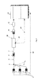
- Fig. 1
- eine prinzipielle Darstellung der ersten Ausführungsform,
- Fig. 2
- eine prinzipielle Darstellung der zweiten und dritten Ausführungsform,
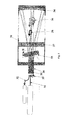
- Fig. 3
- einen prinzipiellen Längsschnitt durch eine selbstreferenzierende Messzelle gemäß der zweiten, in
Fig. 2 dargestellten Ausführungsform mit Hilfe eines kippenden Glasplättchens und - Fig. 4
- einen prinzipiellen Längsschnitt durch eine zweite selbstreferenzierende Messzelle gemäß der zweiten, in
Fig. 2 dargestellten Ausführungsform. - Die in
Fig. 1 dargestellte erste Ausführungsform einer Vorrichtung zum Messen von Stoffenkonzentrationen in Medien umfasst 1 ... n spektral selektive breitbandige Lichtquellen 1, bspw. LEDs, die über Lichtwellenleiter 2 einem ersten Faserkoppler 3 zugeführt, dort gemischt und auf einen Lichtpfad gekoppelt werden. Ein an den ersten Koppler 3 angeschlossener Lichtwellenleiter 4 ist über einen Modenkoppler 5 einem zweiten Faserkoppler 6 (z.B. 75/25) zugeführt. - Von diesem gehen zwei weitere Lichtwellenleiter 7 und 8 ab, von denen der Lichtwellenleiter 7 über einen Modenkoppler 9 zu einer das zu messende Medium enthaltenden Messzelle 10, weiter zu einem ersten Fotoempfänger 11, zu einem A/D-Wandler 12 und dann zu einem Rechner 13, z.B. einem µC oder einem DSP geführt ist. Der weitere Lichtwellenleiter 8 führt das Quellenlicht über einen Modenkoppler 14 zu einem zweiten Fotoempfänger 15, einem A/D- Wandler 16 und dann zu dem o.g. Rechner. Durch geeignete Signalverarbeitung, z.B. Referenzierung durch Vergleich der beiden Empfangskanäle, wird eine faseroptische Referenzierung ermöglicht. Somit ist eine sehr genaue Konzentrationsmessung der in der Messstrecke der Messzelle 10 befindlichen Stoffe realisierbar. Die elektronische Ansteuerung der spektral selektiven Lichtquellen erfolgt über den o.g. Rechner via Ansteuerleitung 18, was günstig für synchrone Ansteuerung und Signalaufnahme bzgl. hoher Messraten ist.
- Erfindungsgemäß erfolgt die Homogenisierung der Abstrahlcharakteristik der 1 ... n spektral selektiven Lichtquellen 1 durch die Verwendung der Modenkoppler 5, 9, 14. Die anschließende Aufteilung des Lichtes ist somit nicht mehr von der schwankenden Intensitätsverteilung der Lichtquellen 1 abhängig. Das eingestrahlte Licht "vergisst" quasi, wo es herkommt. Dabei wird die Modenkopplung hier über die Modenkoppler 5, 9, 14 in den optischen Lichtwellenleitern 2, 4, 7, 8 eingesetzt. Hierfür gibt es unterschiedliche Ausführungsmöglichkeiten, wie z.B. Nutzung sehr langer Fasern, Taper, mehrdimensionale Biegekoppler und dgl. Mit den Modenkopplern 5, 9, 14 wird ein effizientes optisches Bauelement zur Homogenisierung der Abstrahlcharakteristik verwendet.
- Die Schwankungen der gefilterten spektral selektiven breitbandigen Lichtquellen 1 ... n, insbesondere LEDs, werden mit Hilfe der Referenzanordnung, bestehend aus dem Lichtpfad des Lichtwellenleiters 8, mit Modenkoppler 14 und dem zweiten Fotoempfänger 15 sowie dem zugehörigen A/D-Wandler 16 mit entsprechender Signalverarbeitung, im Rechner 13 kompensiert. Die durch die Messanordnung und Umgebung bedingten Störgrößen werden somit gegenüber der Zielgröße unterdrückt. Die Messsignalsicherheit ist daher wesentlich größer und speziell dadurch werden höhere Messgenauigkeiten/Auflösungen erreicht. Durch den Einsatz der Modenkoppler 5, 9, 14, ausgeführt z.B. als Ringkoppler, und der Faserkoppler 3, 6 zur Teilung des Lichtes wird eine quellenunabhängige, robuste und somit exakte Referenzierung ermöglicht, um so z.B. Gaskonzentrationen von unter 1 ppm bei einer Absorptionslange von wenigen Zentimetern bei einer Messzeit von wenigen Millisekunden zu messen.
- Die in
Fig. 2 gezeigte Darstellung der zweiten Ausführungsform umfasst in gleicher Weise wie die inFig. 1 gezeigte erste Ausführungsform die 1 ... n spektral selektiven breitbandigen Lichtquellen 1, die Lichtwellenleiter 2, den Faserkoppler 3, den Modenkoppler 5, die Lichtwellenleiter 4, 7, die Messzelle 20 mit der Messstrecke, den Fotoempfänger 11, den A/D-Wandler 12 und den Rechner 13. Im Gegensatz zur ersten Ausführungsform nachFig. 1 fehlt hier die faseroptische Lichtaufteilung mit dem Referenzpfad. Hier ist die Messzelle 20 selbstreferenzierend ausgeführt, dazu wird der Lichtpfad bspw. entsprechend der Darstellungen inFig. 3 bzw.Fig. 4 oder entsprechend der dritten Ausführungsform moduliert. Zum Zwecke der Detektion der zuletzt genannten Modulation ist der Sensor 21 mit der Messleitung 19 integriert, welche genau wie der Fotoempfänger dem Rechner Messwerte zuführt. Im Rechner findet eine entsprechende Demodulation der Messsignale statt, mit deren Ergebnis die Referenzierung erfolgt. - In der zweiten Ausführungsform nach
Fig. 2 ist somit eine selbstreferenzierende Messzellenanordnung vorgesehen, um so eine Quellunabhängigkeit und somit die gewünschten Genauigkeiten zu erreichen. Auch hier werden zunächst die Kopplung im Faserkoppler 3 und die Modenmischung der einzelnen Lichtquellen 1 mit Hilfe von Faseroptiken in dem Modenkoppler 5 genutzt, um für alle Wellenlangen einen möglichst gleichen Pfad durch die optische Messzelle 20 der Messstrecke zu erhalten. Somit wirken sich Störeinflüsse in der Messzelle 20 z.B. auf die Absorptions-und Referenzwellenlangen in gleicher Weise aus. - Im Gegensatz zu der ersten Ausführungsform nach
Fig. 1 wird hier auf Lichtteilung und somit auf einen zweiten Empfangskanal zur Referenzierung verzichtet. Stattdessen wird die effektive Absorptionslange der Messzelle verändert (selbstreferenzierend) und somit das Messsignal in definierter Weise moduliert, wie es durch Störungen nicht möglich ist. Der durch den einen Empfangsteil aufgenommene Signalverlauf kann entsprechend demoduliert werden. Hierdurch werden zumindest zwei Signale generiert, die zur Referenzierung jeder einzelnen Wellenlange dienen. Der Vorteil dieser Anordnung liegt darin, dass der gesamte optische Pfad außerhalb der Messzelle 20 derselbe ist und nur innerhalb der Messzelle 20 durch die Modulation verändert wird. Dadurch ist nur eine Empfangseinheit notwendig, es müssen nicht zwei gleichartige Empfänger realisiert werden. Somit wirken sich Empfangsstörungen in gleicher Weise auf das Referenz- wie auf das Messsignal aus. Nachteilig ist hier der komplexere Aufbau der Messzelle 30, 40. - Speziell für gasförmige Medien kann eine weitere Art der Referenzierung realisiert werden, indem das indirekte Verfahren der optischen Spektroskopie mit Hilfe einer einfachen Messzelle wie sie in Anwendungsfall 1 beschrieben ist auf einen anderen direkten Sensoreffekt überführt wird. Dies wird durch zusätzliche Modulation der Messgröße, z.B. durch Variation des Druckes realisiert, so ändern sich die Volumenkonzentration des Gases und somit die detektierten Extinktionsmesswerte der einzelnen Quellen. Nimmt man synchron die Variation dieses zusätzlichen physikalischen Effektes bspw. unter Nutzung eines kommerziellen Sensors 21 auf (z.B. den Druck), so lasst sich der Effekt der Modulation nutzen, um das gesamte System sehr genau zu referenzieren, Störungen werden so unterdrückt und die realen Konzentrationsmesswerte bei Normdruck ermittelt. Da in vielen Systemen Druckschwankungen innert sind, ist dies eine sehr einfache und effektive Methode zur Selbstreferenzierung der Messzelle.
- Die weitere Ausführungsform nach
Fig. 3 zeigt die Messzelle 30, in der sich die zu messenden Stoffe befinden, mit Ein- und Ausgängen 31, 32 für das von den Lichtquellen 1 abgestrahlte und über den Lichtwellenleiter 4 und den Modenkoppler 5 der Messzelle 30 und von dieser über den Lichtwellenleiter 7 dem Fotoempfänger 11 zugeführte Licht. In die Messzelle 30 ist eine Glasplatte bzw. ein Glasplättchen 33 integriert, durch dessen Kippen oder Rotieren die effektive Weglänge durch das zu messende Medium in der Messzelle 30 umgeschaltet/variiert wird. In der Position II des Glasplättchens 33 folgt das Licht prinzipiell der Richtung, welche durch den Pfeil 38 markiert ist. In der Position I des Glasplättchens 33 folgt es den Pfeilen 39 auch über die Ein- und Ausgänge 35, 36. Somit wird eine Referenz durch die Interaktion mit dem Medium im Messvolumen der Messzelle 30 erzeugt. Vorteilhaft erweist sich hier, dass das Licht auf beiden Wegen, d.h. auf beiden Positionen I und II, dieselben optischen Komponenten durchlaufen hat. Durch die Verwendung eines Hohlspiegels 34 als Reflektor am rechten Ende der Messzelle 30 (Fig. 3 ) werden wellenabhängige Effekte der Dispersion minimiert. Hier konnte jedoch auch ein Planspiegel eingesetzt werden, dann würde jedoch die optionale Glasplatte 37, die das Messvolumen begrenzt, durch eine Kollimatorlinse ersetzt werden. - Bei der Ausführungsform gemäß
Fig. 4 der selbstreferenzierenden Messzelle 40 wird ein Teil des über den Eingang 31 eingekoppelten und in der Kollimatorlinse 41 kollimierten Lichtes entsprechend der Richtung 45 am halbdurchlässigen Spiegel 42 reflektiert. Dieses reflektierte Licht tritt dann wieder durch die Kollimatorlinse 41, wird zum Ausgang 32 und schließlich zum Empfangsteil 11, 12, 13 geleitet. Ein zweiter Teil des eingekoppelten Lichtes passiert entsprechend der Richtung 4 6 den halbdurchlässigen Spiegel 42 und gelangt in das zweite Messvolumen II. In Abhängigkeit von der Orientierung eines Rotors 44 im optischen Pfad wird dieser Teil des Lichtes an einem Vollspiegel 43 (inFig. 4 rechts) reflektiert und gelangt entsprechend der Reflexion 47 zum Ausgang 32 bzw. zur Empfangseinheit 11, 12, 13. - Der Rotor 44 wird z.B. durch die Strömung des zu messenden Mediums, welches die Messzelle 40 im Messvolumen II in Richtung der Pfeile 48 durchströmt, angetrieben. Die Flügel des Rotors 44 dienen der Lichtabschottung und modulieren somit die effektive Weglänge des Lichts bzw. entsprechend die Stärke der Interaktion des Lichtes mit dem Medium. Dabei befindet sich im Messvolumen I und II der Messzelle 40 dasselbe zu messende Medium.
- Als ein Anwendungsfall der oben abgehandelten Verfahren zur Referenzierung und zur Realisierung kostengünstiger, hochgenauer spektroskopischer Sensoren, wird hier der Abgassensor für Verbrennungsprozesse bzw. -motoren auf der Basis von neuartigen UV-LEDs angeführt. Dieser Sensor ist auch konstruktiv für den Einsatz in extrem rauer Umgebung, wie z.B. dem Abgaskanal eines Pkw, geeignet und erprobt (u.a. hohe Temperaturen, Vibrationen, chemisch aggressive Medien).
-
- 01
- Lichtquelle
- 02
- Lichtwellenleiter
- 03
- Faserkoppler
- 04
- Lichtwellenleiter
- 05
- Modenkoppler
- 06
- Faserkoppler
- 07
- Lichtwellenleiter
- 08
- Lichtwellenleiter
- 09
- Modemkoppler
- 10
- Messzelle
- 11
- Fotoempfänger
- 12
- Analog-/Digitalwandler (A/D-Wandler)
- 13
- Rechner
- 14
- Modenkoppler
- 15
- Fotoempfänger
- 16
- A/D-Wandler
- 18
- Quellenansteuerleitung
- 19
- Messleitung
- 20
- referenzierende Messzelle
- 22
- Sensor
- 30
- Messzelle
- 31
- Lichteingang für nicht stabilisierte Lichtquelle bzw. gestörte Zuleitung
- 32
- Lichtausgang, zum Fotoempfänger
- 33
- Glasplatte
- 34
- Hohlspiegel als Reflektor
- 35
- Eingang zur Lichtrückführung
- 36
- Ausgang der Lichtrückführung
- 37
- Optionale Glasplatte
- 38
- Richtung des ersten Lichtpfades
- 39
- Richtung des zweiten Lichtpfades
- 40
- Messzelle
- 41
- Kollimatorlinse
- 42
- Halbdurchlässiger Spiegel
- 43
- Vollspiegel
- 44
- Rotor
- 45
- Richtung des ersten Teillichtstromes
- 46
- Richtung des zweiten Teillichtstromes
- 47
- Reflexion des zweiten Teillichtstromes
- 48
- Richtung der Anströmung
Claims (7)
- Verfahren zur Bestimmung von Stoffkonzentrationen in gasförmigen oder fluiden Medien mittels optischer Absorptionsspektroskopie, mit 1 bis n spektral selektiven Breitbandlichtquellen (1), insbesondere LEDs, wobei das Licht der Breitbandlichtquellen (1) durch erste Lichtwellenleiter (2) in einen gemeinsamen zweiten Lichtwellenleiter (4) eines Lichtpfads gekoppelt und dann zu einer Messstrecke einer Messzelle (20, 30, 40) mit einem gasförmigen oder fluiden Medium geleitet wird, wobei die Messzelle (20, 30, 40) als selbstreferenzierende Messzelle (20, 30, 40) ausgebildet ist, in der die effektive Absorptionslänge der Messzelle (20, 30, 40) veränderbar ist, dadurch gekennzeichnet, dass die zeitlich und örtlich schwankende Abstrahlcharakteristik der Breitbandlichtquellen (1) mittels eines Modenkopplers (5) im Lichtpfad zwischen dem zweiten Lichtwellenleiter (4) und der Messzelle (20, 30, 40) homogenisiert wird.
- Vorrichtung zur Bestimmung von Stoffkonzentrationen in gasförmigen oder fluiden Medien mittels optischer Absorptionsspektroskopie, mit 1 bis n spektral selektiven Breitbandlichtquellen (1), insbesondere LEDs, die durch erste Lichtwellenleiter (2) mit einem ersten Lichtwellenleiter- oder Faserkoppler (3) verbunden sind, einem an den Lichtwellenleiter- oder Faserkoppler (3) angeschlossenen gemeinsamen zweiten Lichtwellenleiter (4), der das Licht der Breitbandlichtquellen (1) zu einer Messzelle (20, 30, 40) mit einer Messstrecke leitet, sowie einem Messdetektor (11), der mit der Messzelle (20, 30, 40) verbunden ist und dem das von den Breitbandlichtquellen (1) zugeführte Licht durch die Messstrecke zugeleitet wird, wobei die Messzelle (20, 30, 40) als selbstreferenzierenden Messzelle (20, 30, 40) ausgebildet ist, in der die effektive Absorptionslänge der Messzelle (20, 30, 40) veränderbar ist, gekennzeichnet durch einen Modenkoppler (5) im Lichtpfad zwischen dem ersten Lichtwellenleiter- oder Faserkoppler (3) und der Messzelle (20, 30, 40) zur Homogenisierung der zeitlichen und örtlich schwankenden Abstrahlcharakteristik der Breitbandlichtquellen (1).
- Vorrichtung nach Anspruch 2, dadurch gekennzeichnet, dass in der Messzelle (20, 30, 40) die Interaktionslänge des zu messenden Mediums zur Erzeugung eines Referenzsignals veränderbar ist.
- Vorrichtung nach Anspruch 3, dadurch gekennzeichnet, dass zur Veränderung der Interaktionslänge des zu messenden Mediums in der Messzelle (30) ein kippbares oder drehbares Glasplättchen (33) angeordnet ist.
- Vorrichtung nach Anspruch 4, dadurch gekennzeichnet, dass am Ende der Messzelle (30) ein Hohlspiegel (34) als Reflektor eingesetzt ist.
- Vorrichtung nach Anspruch 3, dadurch gekennzeichnet, dass die selbstreferenzierende Messstrecke der Messzelle (40) einen halbdurchlässigen Spiegel (42) und einen Vollspiegel (43) umfasst, wobei ein zusätzlicher Rotor (44), welcher durch das strömende zu messende Medium angetrieben sein kann und sich im optischen Pfad befindet, den Vollspiegel (43) zeitweise abschattet.
- Vorrichtung nach Anspruch 3, dadurch gekennzeichnet, dass die Messzelle (20) einen zusätzlichen Sensor (21) zur Erfassung einer Druckänderung umfasst, durch die ein vom Messdetektor (11) erfasstes Messsignal in definierter Weise verändert wird.
Applications Claiming Priority (2)
| Application Number | Priority Date | Filing Date | Title |
|---|---|---|---|
| DE102008064173A DE102008064173B4 (de) | 2008-12-22 | 2008-12-22 | Verfahren und Vorrichtung zur Bestimmung der Stoffkonzentration in gasförmigen oder fluiden Medien mittels optischer Absorptionsspektroskopie mit Breitbandlichtquellen |
| EP09796360.7A EP2380005B1 (de) | 2008-12-22 | 2009-12-10 | Verfahren und vorrichtung zum messen der stoffkonzentration in gasförmigen oder fluiden medien über optische spektroskopie mittels breitbandiger lichtquellen |
Related Parent Applications (2)
| Application Number | Title | Priority Date | Filing Date |
|---|---|---|---|
| EP09796360.7A Division-Into EP2380005B1 (de) | 2008-12-22 | 2009-12-10 | Verfahren und vorrichtung zum messen der stoffkonzentration in gasförmigen oder fluiden medien über optische spektroskopie mittels breitbandiger lichtquellen |
| EP09796360.7A Division EP2380005B1 (de) | 2008-12-22 | 2009-12-10 | Verfahren und vorrichtung zum messen der stoffkonzentration in gasförmigen oder fluiden medien über optische spektroskopie mittels breitbandiger lichtquellen |
Publications (2)
| Publication Number | Publication Date |
|---|---|
| EP3009829A1 true EP3009829A1 (de) | 2016-04-20 |
| EP3009829B1 EP3009829B1 (de) | 2017-03-08 |
Family
ID=41664703
Family Applications (2)
| Application Number | Title | Priority Date | Filing Date |
|---|---|---|---|
| EP09796360.7A Active EP2380005B1 (de) | 2008-12-22 | 2009-12-10 | Verfahren und vorrichtung zum messen der stoffkonzentration in gasförmigen oder fluiden medien über optische spektroskopie mittels breitbandiger lichtquellen |
| EP15192390.1A Active EP3009829B1 (de) | 2008-12-22 | 2009-12-10 | Verfahren und vorrichtung zum messen der stoffkonzentration in gasförmigen oder fluiden medien über optische spektroskopie mittels breitbandiger lichtquellen |
Family Applications Before (1)
| Application Number | Title | Priority Date | Filing Date |
|---|---|---|---|
| EP09796360.7A Active EP2380005B1 (de) | 2008-12-22 | 2009-12-10 | Verfahren und vorrichtung zum messen der stoffkonzentration in gasförmigen oder fluiden medien über optische spektroskopie mittels breitbandiger lichtquellen |
Country Status (6)
| Country | Link |
|---|---|
| US (2) | US20120006098A1 (de) |
| EP (2) | EP2380005B1 (de) |
| DE (1) | DE102008064173B4 (de) |
| ES (2) | ES2565413T3 (de) |
| GB (1) | GB2478254A (de) |
| WO (1) | WO2010072578A1 (de) |
Families Citing this family (18)
| Publication number | Priority date | Publication date | Assignee | Title |
|---|---|---|---|---|
| DE102010062027A1 (de) * | 2010-11-26 | 2012-05-31 | Siemens Aktiengesellschaft | Messaufbau für die optische Absorptions-Spektroskopie |
| DE102011116367A1 (de) | 2011-10-19 | 2013-04-25 | Bluepoint Medical Gmbh & Co. Kg | Vorrichtung zur hoch aufgelösten Bestimmung der Konzentration von Substanzen in fluiden Medien |
| US8953157B2 (en) * | 2012-02-01 | 2015-02-10 | Wisconsin Alumni Research Foundation | Monolithic fiber optic sensor assembly |
| US10151685B2 (en) | 2012-04-16 | 2018-12-11 | Sensor Electronic Technology, Inc. | Ultraviolet-based gas sensor |
| US9625372B2 (en) | 2012-04-16 | 2017-04-18 | Sensor Electronic Technology, Inc. | Ultraviolet-based ozone sensor |
| WO2017029792A1 (ja) * | 2015-08-18 | 2017-02-23 | 国立大学法人徳島大学 | 濃度測定装置 |
| DE102015221789A1 (de) | 2015-11-06 | 2017-05-11 | Robert Bosch Gmbh | Absorptionsspektroskopische Sensoranordnung und Verfahren zur Bestimmung einer Stoffkonzentration in einem gasförmigen Medium |
| EP3270045B1 (de) | 2016-07-11 | 2023-06-07 | Bluepoint Medical GmbH & Co. KG | Anordnung zum messen von gaskonzentrationen |
| JP6912766B2 (ja) * | 2016-07-29 | 2021-08-04 | 国立大学法人徳島大学 | 濃度測定装置 |
| CN107643260B (zh) * | 2017-11-06 | 2024-05-03 | 汉威科技集团股份有限公司 | 一种宽光谱多参数水质监测系统 |
| US11346772B2 (en) | 2018-01-16 | 2022-05-31 | Ows Agri Limited | Gas concentration measurement apparatus and techniques |
| WO2019147215A1 (en) * | 2018-01-23 | 2019-08-01 | Ows Agri Limited | System and method for ozone concentration measurement in liquids having a negative scaling index |
| WO2019147220A1 (en) | 2018-01-23 | 2019-08-01 | Ows Agri Limited | System and method for ozone concentration measurement in ice |
| WO2019147234A1 (en) | 2018-01-24 | 2019-08-01 | Ows Agri Limited | System and method for ozone concentration in liquids having a positive scaling factor |
| WO2019151976A1 (en) | 2018-01-30 | 2019-08-08 | Ows Agri Limited | Systems and methods for bulk sterilization using ozone |
| US11712052B2 (en) | 2018-02-09 | 2023-08-01 | Ows Agri Limited | Systems and methods for continuous flow sterilization |
| EP3779408A1 (de) * | 2019-08-15 | 2021-02-17 | optek-Danulat GmbH | Messvorrichtung und verfahren zur bestimmung einer stoffkonzentration |
| GB2702852A (en) * | 2024-12-05 | 2026-07-01 | Res & Innovation Uk | Spectroscopic monitoring of gas in liquid |
Citations (4)
| Publication number | Priority date | Publication date | Assignee | Title |
|---|---|---|---|---|
| EP0145877A2 (de) * | 1983-11-04 | 1985-06-26 | Hartmann & Braun Aktiengesellschaft | Fotometer zur kontinuierlichen Analyse eines Mediums (Gas oder Flüssigkeit) |
| GB2233087A (en) * | 1989-05-31 | 1991-01-02 | York Ltd | Apparatus for monitoring a gas or a flame |
| WO1993006458A1 (en) * | 1991-09-26 | 1993-04-01 | The Dow Chemical Company | Variable path length light transmission probe |
| WO2005108939A1 (en) * | 2004-05-12 | 2005-11-17 | Macquarie University | Cavity ringdown spectroscopy with swept-frequency laser |
Family Cites Families (11)
| Publication number | Priority date | Publication date | Assignee | Title |
|---|---|---|---|---|
| US3811776A (en) * | 1973-02-26 | 1974-05-21 | Environmental Res & Tech | Gas analyzer |
| US5012809A (en) * | 1986-10-10 | 1991-05-07 | Shulze John E | Fiber optic catheter system with fluorometric sensor and integral flexure compensation |
| SE8802536D0 (sv) * | 1988-07-07 | 1988-07-07 | Altoptronic Ab | Metod och apparat for spektroskopisk metning av koncentrationen av en gas i ett prov |
| JPH07151684A (ja) | 1993-11-29 | 1995-06-16 | Shimadzu Corp | 赤外線式ガス分析計 |
| US5445964A (en) * | 1994-05-11 | 1995-08-29 | Lee; Peter S. | Dynamic engine oil and fuel consumption measurements using tunable diode laser spectroscopy |
| US5693945A (en) * | 1994-07-30 | 1997-12-02 | Horiba Ltd. | Gas analyzer |
| US5528040A (en) * | 1994-11-07 | 1996-06-18 | Trustees Of Princeton University | Ring-down cavity spectroscopy cell using continuous wave excitation for trace species detection |
| US5572031A (en) * | 1994-11-23 | 1996-11-05 | Sri International | Pressure- and temperature-compensating oxygen sensor |
| US5818598A (en) * | 1996-12-20 | 1998-10-06 | Aerodyne Research, Inc. | Nondispersive optical monitor for nitrogen-oxygen compounds |
| KR100419094B1 (ko) * | 2001-06-28 | 2004-02-19 | (주)나노믹스 | 기체 식별기 |
| JP4411599B2 (ja) * | 2004-10-26 | 2010-02-10 | 横河電機株式会社 | 赤外線ガス分析計および赤外線ガス分析方法 |
-
2008
- 2008-12-22 DE DE102008064173A patent/DE102008064173B4/de active Active
-
2009
- 2009-12-10 US US13/141,380 patent/US20120006098A1/en not_active Abandoned
- 2009-12-10 ES ES09796360.7T patent/ES2565413T3/es active Active
- 2009-12-10 EP EP09796360.7A patent/EP2380005B1/de active Active
- 2009-12-10 EP EP15192390.1A patent/EP3009829B1/de active Active
- 2009-12-10 WO PCT/EP2009/066840 patent/WO2010072578A1/de not_active Ceased
- 2009-12-10 GB GB1111225A patent/GB2478254A/en not_active Withdrawn
- 2009-12-10 ES ES15192390.1T patent/ES2626574T3/es active Active
-
2016
- 2016-08-02 US US15/226,614 patent/US10408745B2/en not_active Expired - Fee Related
Patent Citations (4)
| Publication number | Priority date | Publication date | Assignee | Title |
|---|---|---|---|---|
| EP0145877A2 (de) * | 1983-11-04 | 1985-06-26 | Hartmann & Braun Aktiengesellschaft | Fotometer zur kontinuierlichen Analyse eines Mediums (Gas oder Flüssigkeit) |
| GB2233087A (en) * | 1989-05-31 | 1991-01-02 | York Ltd | Apparatus for monitoring a gas or a flame |
| WO1993006458A1 (en) * | 1991-09-26 | 1993-04-01 | The Dow Chemical Company | Variable path length light transmission probe |
| WO2005108939A1 (en) * | 2004-05-12 | 2005-11-17 | Macquarie University | Cavity ringdown spectroscopy with swept-frequency laser |
Non-Patent Citations (1)
| Title |
|---|
| M. DEGNER; H. EWALD: "Low cost sensor for online detection of harmful diesel combustion gases in UV-VIS region", SPIE PHOTONICS EUROPE 2006, PHOTONICS IN THE AUTOMOBILE, vol. II, April 2006 (2006-04-01) |
Also Published As
| Publication number | Publication date |
|---|---|
| GB201111225D0 (en) | 2011-08-17 |
| ES2626574T3 (es) | 2017-07-25 |
| US20160341660A1 (en) | 2016-11-24 |
| ES2565413T3 (es) | 2016-04-04 |
| DE102008064173A1 (de) | 2010-07-01 |
| WO2010072578A1 (de) | 2010-07-01 |
| EP2380005B1 (de) | 2016-01-27 |
| EP3009829B1 (de) | 2017-03-08 |
| DE102008064173B4 (de) | 2011-06-01 |
| EP2380005A1 (de) | 2011-10-26 |
| GB2478254A (en) | 2011-08-31 |
| US20120006098A1 (en) | 2012-01-12 |
| US10408745B2 (en) | 2019-09-10 |
Similar Documents
| Publication | Publication Date | Title |
|---|---|---|
| DE102008064173B4 (de) | Verfahren und Vorrichtung zur Bestimmung der Stoffkonzentration in gasförmigen oder fluiden Medien mittels optischer Absorptionsspektroskopie mit Breitbandlichtquellen | |
| DE68924163T2 (de) | Verfahren und vorrichtung zur spektroskopischen messung der gaskonzentration. | |
| EP3622270B1 (de) | Gasmesssystem | |
| DE102010037620B4 (de) | Systeme und Verfahren zur Regelung von Emissionen | |
| EP0318752B1 (de) | System zur Spuren- Gasanalyse | |
| EP0054292A2 (de) | Faseroptische Messeinrichtung | |
| DE19615366A1 (de) | Verfahren und Einrichtung zum Nachweis physikalischer, chemischer, biologischer oder biochemischer Reaktionen und Wechselwirkungen | |
| DE112011103836T5 (de) | Spektrophotometer | |
| EP3598103B1 (de) | Gasanalysator und gasanalyseverfahren | |
| AT525495A2 (de) | Ausgleichsdetektion mit ICAPS innerhalb einer optischen Kavität | |
| EP0401576B1 (de) | Interferometeranordnung | |
| EP3270045B1 (de) | Anordnung zum messen von gaskonzentrationen | |
| EP2584328A1 (de) | Vorrichtung zur hoch aufgelösten Bestimmung der Konzentration von Substanzen in fluiden Medien | |
| DE102006014568B4 (de) | Vorrichtung zur Bestimmung der Wellenlänge, Wellenlängenmessinstrument ausgerüstet mit der Vorrichtung, Verfahren, Programm und Speichermedium zur Bestimmung der Wellenlänge | |
| EP1780572A1 (de) | Anordnung zur Erfassung der Beleuchtungsstrahlung in einem Laser-Scanning-Mikroskop | |
| DE102004031643A1 (de) | Nichtdispersiver Infrarot-Gasanalysator | |
| DE4129085A1 (de) | Optischer sensor fuer rotationsbewegungen | |
| DE19541516C2 (de) | Vorrichtung zur optischen Bestimmung der Sauerstoffkonzentration und deren Änderung im Abgas eines Verbrennungssystems zur Kontrolle und/oder Regelung des Verbrennungsprozesses | |
| DE102005045538B3 (de) | Vorrichtung und Verfahren zur Bestimmung des Brechungsindex eines Fluids | |
| DE10202999B4 (de) | Verfahren und Vorrichtung zum Messen der Größenverteilung und Konzentration von Partikeln in einem Fluid | |
| DE102013205848B3 (de) | Optisches Temperatursensorsystem | |
| EP4553488A1 (de) | Reduktion von optischen störsignalen mittels schwingungsbewegungen von optisch aktiven elementen eines spektrometers | |
| EP0895588B1 (de) | Untersuchungsvorrichtung | |
| WO2025132052A2 (de) | Strahlungsquelleneinheit zum durchführen einer optischen messung, optisches messsystem und verfahren zum herstellen einer strahlungsquelleneinheit | |
| EP3575759B1 (de) | Spektrometer und verfahren zum betrieb |
Legal Events
| Date | Code | Title | Description |
|---|---|---|---|
| PUAI | Public reference made under article 153(3) epc to a published international application that has entered the european phase |
Free format text: ORIGINAL CODE: 0009012 |
|
| AC | Divisional application: reference to earlier application |
Ref document number: 2380005 Country of ref document: EP Kind code of ref document: P |
|
| AK | Designated contracting states |
Kind code of ref document: A1 Designated state(s): AT BE BG CH CY CZ DE DK EE ES FI FR GB GR HR HU IE IS IT LI LT LU LV MC MK MT NL NO PL PT RO SE SI SK SM TR |
|
| 17P | Request for examination filed |
Effective date: 20161007 |
|
| RBV | Designated contracting states (corrected) |
Designated state(s): AT BE BG CH CY CZ DE DK EE ES FI FR GB GR HR HU IE IS IT LI LT LU LV MC MK MT NL NO PL PT RO SE SI SK SM TR |
|
| GRAP | Despatch of communication of intention to grant a patent |
Free format text: ORIGINAL CODE: EPIDOSNIGR1 |
|
| INTG | Intention to grant announced |
Effective date: 20161122 |
|
| GRAS | Grant fee paid |
Free format text: ORIGINAL CODE: EPIDOSNIGR3 |
|
| GRAA | (expected) grant |
Free format text: ORIGINAL CODE: 0009210 |
|
| AC | Divisional application: reference to earlier application |
Ref document number: 2380005 Country of ref document: EP Kind code of ref document: P |
|
| AK | Designated contracting states |
Kind code of ref document: B1 Designated state(s): AT BE BG CH CY CZ DE DK EE ES FI FR GB GR HR HU IE IS IT LI LT LU LV MC MK MT NL NO PL PT RO SE SI SK SM TR |
|
| REG | Reference to a national code |
Ref country code: GB Ref legal event code: FG4D Free format text: NOT ENGLISH |
|
| REG | Reference to a national code |
Ref country code: CH Ref legal event code: EP Ref country code: AT Ref legal event code: REF Ref document number: 873963 Country of ref document: AT Kind code of ref document: T Effective date: 20170315 |
|
| REG | Reference to a national code |
Ref country code: IE Ref legal event code: FG4D Free format text: LANGUAGE OF EP DOCUMENT: GERMAN |
|
| REG | Reference to a national code |
Ref country code: DE Ref legal event code: R096 Ref document number: 502009013733 Country of ref document: DE |
|
| REG | Reference to a national code |
Ref country code: SE Ref legal event code: TRGR |
|
| REG | Reference to a national code |
Ref country code: CH Ref legal event code: NV Representative=s name: ISLER AND PEDRAZZINI AG, CH |
|
| REG | Reference to a national code |
Ref country code: LT Ref legal event code: MG4D |
|
| REG | Reference to a national code |
Ref country code: NL Ref legal event code: MP Effective date: 20170308 |
|
| REG | Reference to a national code |
Ref country code: ES Ref legal event code: FG2A Ref document number: 2626574 Country of ref document: ES Kind code of ref document: T3 Effective date: 20170725 |
|
| PG25 | Lapsed in a contracting state [announced via postgrant information from national office to epo] |
Ref country code: HR Free format text: LAPSE BECAUSE OF FAILURE TO SUBMIT A TRANSLATION OF THE DESCRIPTION OR TO PAY THE FEE WITHIN THE PRESCRIBED TIME-LIMIT Effective date: 20170308 Ref country code: FI Free format text: LAPSE BECAUSE OF FAILURE TO SUBMIT A TRANSLATION OF THE DESCRIPTION OR TO PAY THE FEE WITHIN THE PRESCRIBED TIME-LIMIT Effective date: 20170308 Ref country code: LT Free format text: LAPSE BECAUSE OF FAILURE TO SUBMIT A TRANSLATION OF THE DESCRIPTION OR TO PAY THE FEE WITHIN THE PRESCRIBED TIME-LIMIT Effective date: 20170308 Ref country code: GR Free format text: LAPSE BECAUSE OF FAILURE TO SUBMIT A TRANSLATION OF THE DESCRIPTION OR TO PAY THE FEE WITHIN THE PRESCRIBED TIME-LIMIT Effective date: 20170609 Ref country code: NO Free format text: LAPSE BECAUSE OF FAILURE TO SUBMIT A TRANSLATION OF THE DESCRIPTION OR TO PAY THE FEE WITHIN THE PRESCRIBED TIME-LIMIT Effective date: 20170608 |
|
| PG25 | Lapsed in a contracting state [announced via postgrant information from national office to epo] |
Ref country code: BG Free format text: LAPSE BECAUSE OF FAILURE TO SUBMIT A TRANSLATION OF THE DESCRIPTION OR TO PAY THE FEE WITHIN THE PRESCRIBED TIME-LIMIT Effective date: 20170608 Ref country code: LV Free format text: LAPSE BECAUSE OF FAILURE TO SUBMIT A TRANSLATION OF THE DESCRIPTION OR TO PAY THE FEE WITHIN THE PRESCRIBED TIME-LIMIT Effective date: 20170308 |
|
| PG25 | Lapsed in a contracting state [announced via postgrant information from national office to epo] |
Ref country code: NL Free format text: LAPSE BECAUSE OF FAILURE TO SUBMIT A TRANSLATION OF THE DESCRIPTION OR TO PAY THE FEE WITHIN THE PRESCRIBED TIME-LIMIT Effective date: 20170308 |
|
| PG25 | Lapsed in a contracting state [announced via postgrant information from national office to epo] |
Ref country code: EE Free format text: LAPSE BECAUSE OF FAILURE TO SUBMIT A TRANSLATION OF THE DESCRIPTION OR TO PAY THE FEE WITHIN THE PRESCRIBED TIME-LIMIT Effective date: 20170308 Ref country code: SK Free format text: LAPSE BECAUSE OF FAILURE TO SUBMIT A TRANSLATION OF THE DESCRIPTION OR TO PAY THE FEE WITHIN THE PRESCRIBED TIME-LIMIT Effective date: 20170308 Ref country code: RO Free format text: LAPSE BECAUSE OF FAILURE TO SUBMIT A TRANSLATION OF THE DESCRIPTION OR TO PAY THE FEE WITHIN THE PRESCRIBED TIME-LIMIT Effective date: 20170308 Ref country code: CZ Free format text: LAPSE BECAUSE OF FAILURE TO SUBMIT A TRANSLATION OF THE DESCRIPTION OR TO PAY THE FEE WITHIN THE PRESCRIBED TIME-LIMIT Effective date: 20170308 |
|
| PG25 | Lapsed in a contracting state [announced via postgrant information from national office to epo] |
Ref country code: PT Free format text: LAPSE BECAUSE OF FAILURE TO SUBMIT A TRANSLATION OF THE DESCRIPTION OR TO PAY THE FEE WITHIN THE PRESCRIBED TIME-LIMIT Effective date: 20170710 Ref country code: PL Free format text: LAPSE BECAUSE OF FAILURE TO SUBMIT A TRANSLATION OF THE DESCRIPTION OR TO PAY THE FEE WITHIN THE PRESCRIBED TIME-LIMIT Effective date: 20170308 Ref country code: SM Free format text: LAPSE BECAUSE OF FAILURE TO SUBMIT A TRANSLATION OF THE DESCRIPTION OR TO PAY THE FEE WITHIN THE PRESCRIBED TIME-LIMIT Effective date: 20170308 Ref country code: IS Free format text: LAPSE BECAUSE OF FAILURE TO SUBMIT A TRANSLATION OF THE DESCRIPTION OR TO PAY THE FEE WITHIN THE PRESCRIBED TIME-LIMIT Effective date: 20170708 |
|
| REG | Reference to a national code |
Ref country code: DE Ref legal event code: R097 Ref document number: 502009013733 Country of ref document: DE |
|
| REG | Reference to a national code |
Ref country code: FR Ref legal event code: PLFP Year of fee payment: 9 |
|
| PLBE | No opposition filed within time limit |
Free format text: ORIGINAL CODE: 0009261 |
|
| STAA | Information on the status of an ep patent application or granted ep patent |
Free format text: STATUS: NO OPPOSITION FILED WITHIN TIME LIMIT |
|
| PG25 | Lapsed in a contracting state [announced via postgrant information from national office to epo] |
Ref country code: DK Free format text: LAPSE BECAUSE OF FAILURE TO SUBMIT A TRANSLATION OF THE DESCRIPTION OR TO PAY THE FEE WITHIN THE PRESCRIBED TIME-LIMIT Effective date: 20170308 |
|
| 26N | No opposition filed |
Effective date: 20171211 |
|
| PG25 | Lapsed in a contracting state [announced via postgrant information from national office to epo] |
Ref country code: SI Free format text: LAPSE BECAUSE OF FAILURE TO SUBMIT A TRANSLATION OF THE DESCRIPTION OR TO PAY THE FEE WITHIN THE PRESCRIBED TIME-LIMIT Effective date: 20170308 |
|
| REG | Reference to a national code |
Ref country code: IE Ref legal event code: MM4A |
|
| PG25 | Lapsed in a contracting state [announced via postgrant information from national office to epo] |
Ref country code: MT Free format text: LAPSE BECAUSE OF FAILURE TO SUBMIT A TRANSLATION OF THE DESCRIPTION OR TO PAY THE FEE WITHIN THE PRESCRIBED TIME-LIMIT Effective date: 20170308 Ref country code: LU Free format text: LAPSE BECAUSE OF NON-PAYMENT OF DUE FEES Effective date: 20171210 |
|
| REG | Reference to a national code |
Ref country code: BE Ref legal event code: MM Effective date: 20171231 |
|
| PG25 | Lapsed in a contracting state [announced via postgrant information from national office to epo] |
Ref country code: IE Free format text: LAPSE BECAUSE OF NON-PAYMENT OF DUE FEES Effective date: 20171210 |
|
| PG25 | Lapsed in a contracting state [announced via postgrant information from national office to epo] |
Ref country code: BE Free format text: LAPSE BECAUSE OF NON-PAYMENT OF DUE FEES Effective date: 20171231 |
|
| PG25 | Lapsed in a contracting state [announced via postgrant information from national office to epo] |
Ref country code: HU Free format text: LAPSE BECAUSE OF FAILURE TO SUBMIT A TRANSLATION OF THE DESCRIPTION OR TO PAY THE FEE WITHIN THE PRESCRIBED TIME-LIMIT; INVALID AB INITIO Effective date: 20091210 Ref country code: MC Free format text: LAPSE BECAUSE OF FAILURE TO SUBMIT A TRANSLATION OF THE DESCRIPTION OR TO PAY THE FEE WITHIN THE PRESCRIBED TIME-LIMIT Effective date: 20170308 |
|
| PG25 | Lapsed in a contracting state [announced via postgrant information from national office to epo] |
Ref country code: CY Free format text: LAPSE BECAUSE OF FAILURE TO SUBMIT A TRANSLATION OF THE DESCRIPTION OR TO PAY THE FEE WITHIN THE PRESCRIBED TIME-LIMIT Effective date: 20170308 |
|
| PG25 | Lapsed in a contracting state [announced via postgrant information from national office to epo] |
Ref country code: MK Free format text: LAPSE BECAUSE OF FAILURE TO SUBMIT A TRANSLATION OF THE DESCRIPTION OR TO PAY THE FEE WITHIN THE PRESCRIBED TIME-LIMIT Effective date: 20170308 |
|
| PGFP | Annual fee paid to national office [announced via postgrant information from national office to epo] |
Ref country code: SE Payment date: 20191220 Year of fee payment: 11 |
|
| PGFP | Annual fee paid to national office [announced via postgrant information from national office to epo] |
Ref country code: FR Payment date: 20191219 Year of fee payment: 11 Ref country code: IT Payment date: 20191216 Year of fee payment: 11 |
|
| PG25 | Lapsed in a contracting state [announced via postgrant information from national office to epo] |
Ref country code: TR Free format text: LAPSE BECAUSE OF FAILURE TO SUBMIT A TRANSLATION OF THE DESCRIPTION OR TO PAY THE FEE WITHIN THE PRESCRIBED TIME-LIMIT Effective date: 20170308 |
|
| PGFP | Annual fee paid to national office [announced via postgrant information from national office to epo] |
Ref country code: CH Payment date: 20191220 Year of fee payment: 11 |
|
| PGFP | Annual fee paid to national office [announced via postgrant information from national office to epo] |
Ref country code: ES Payment date: 20200122 Year of fee payment: 11 Ref country code: GB Payment date: 20191220 Year of fee payment: 11 |
|
| REG | Reference to a national code |
Ref country code: CH Ref legal event code: PL |
|
| REG | Reference to a national code |
Ref country code: SE Ref legal event code: EUG |
|
| GBPC | Gb: european patent ceased through non-payment of renewal fee |
Effective date: 20201210 |
|
| PG25 | Lapsed in a contracting state [announced via postgrant information from national office to epo] |
Ref country code: IT Free format text: LAPSE BECAUSE OF NON-PAYMENT OF DUE FEES Effective date: 20201210 Ref country code: FR Free format text: LAPSE BECAUSE OF NON-PAYMENT OF DUE FEES Effective date: 20201231 |
|
| PG25 | Lapsed in a contracting state [announced via postgrant information from national office to epo] |
Ref country code: SE Free format text: LAPSE BECAUSE OF NON-PAYMENT OF DUE FEES Effective date: 20201211 Ref country code: CH Free format text: LAPSE BECAUSE OF NON-PAYMENT OF DUE FEES Effective date: 20201231 Ref country code: GB Free format text: LAPSE BECAUSE OF NON-PAYMENT OF DUE FEES Effective date: 20201210 Ref country code: LI Free format text: LAPSE BECAUSE OF NON-PAYMENT OF DUE FEES Effective date: 20201231 |
|
| REG | Reference to a national code |
Ref country code: ES Ref legal event code: FD2A Effective date: 20220221 |
|
| PG25 | Lapsed in a contracting state [announced via postgrant information from national office to epo] |
Ref country code: ES Free format text: LAPSE BECAUSE OF NON-PAYMENT OF DUE FEES Effective date: 20201211 |
|
| PGFP | Annual fee paid to national office [announced via postgrant information from national office to epo] |
Ref country code: DE Payment date: 20241216 Year of fee payment: 16 |
|
| PGFP | Annual fee paid to national office [announced via postgrant information from national office to epo] |
Ref country code: AT Payment date: 20241213 Year of fee payment: 16 |