EP3009772A1 - Sight-glass arrangement for a refrigerant carrying system - Google Patents
Sight-glass arrangement for a refrigerant carrying system Download PDFInfo
- Publication number
- EP3009772A1 EP3009772A1 EP14189123.4A EP14189123A EP3009772A1 EP 3009772 A1 EP3009772 A1 EP 3009772A1 EP 14189123 A EP14189123 A EP 14189123A EP 3009772 A1 EP3009772 A1 EP 3009772A1
- Authority
- EP
- European Patent Office
- Prior art keywords
- sight
- glass
- arrangement according
- ring shaped
- housing
- Prior art date
- Legal status (The legal status is an assumption and is not a legal conclusion. Google has not performed a legal analysis and makes no representation as to the accuracy of the status listed.)
- Granted
Links
Images
Classifications
-
- F—MECHANICAL ENGINEERING; LIGHTING; HEATING; WEAPONS; BLASTING
- F25—REFRIGERATION OR COOLING; COMBINED HEATING AND REFRIGERATION SYSTEMS; HEAT PUMP SYSTEMS; MANUFACTURE OR STORAGE OF ICE; LIQUEFACTION SOLIDIFICATION OF GASES
- F25B—REFRIGERATION MACHINES, PLANTS OR SYSTEMS; COMBINED HEATING AND REFRIGERATION SYSTEMS; HEAT PUMP SYSTEMS
- F25B41/00—Fluid-circulation arrangements
- F25B41/006—Fluid-circulation arrangements optical fluid control arrangements
Definitions
- the invention relates to a sight-glass arrangement for a refrigerant carrying system comprising a housing, a sight-glass through which an interior of said housing is visible, said sight-glass being arranged in an opening in said housing, and a moisture indicator in form of a hollow cylinder element having a ring shaped wall.
- Such a sight-glass arrangement is known, for example, from US 4 018 061 .
- the cylinder element is positioned perpendicular to the opening in the housing so that the radially outer side of the ring shaped wall faces the opening which is covered by the sight-glass.
- a preferred form of moisture indicating means vary the color in direct relation with the variation in moisture content of the refrigerant.
- the part of the moisture indicator visible through the sight-glass has a minimum size. This has the consequence that the moisture indicator covers a relative large part of the window in which the sight-glass is arranged thus preventing inspection of the interior of the housing or of the refrigerant carrying system.
- the moisture indicating means can be, for example, a cobalt salt or cobalt salt solution applied at least to the radially inner side of the hollow cylinder forming the moisture indicator. Since this radially inner side is visible through the sight-glass the area which can change the color in dependency of the variation of moisture content of the refrigerant can in this way have a considerable size which is sufficient to allow a reliable recognition of the change of color.
- said cylinder element is centered with respect to said sight-glass.
- the viewing angle of an operator to the moisture indicator does not play a major role. Independently of this viewing angle the operator is able to recognize a color variation of the moisture indicator or any other change of a visible appearance.
- said cylinder element follows immediately said sight-glass in a direction towards said interior part.
- said cylinder element contacts said sight-glass so that the distance to see the radially inner wall of the cylinder element is as short as possible.
- one of the ring shaped wall and housing comprises protrusions and the other one comprises at least one recess, said protrusion means extending in said recess.
- the protrusion means and the recess cooperate to fix the cylinder element in the housing with simple means.
- the fixing of the cylinder element in the housing defines the position of the cylinder element with respect to the sight-glass and allows for a precise alignment of the cylinder element and the sight-glass and of a distance as short as possible between the cylinder element and the sight-glass.
- said ring shaped wall is at least on a part of its axial lengths deformable in radial direction. This facilitates mounting of the moisture indicator in the housing. Before inserting the moisture indicator into the opening of the housing, it is radially slightly compressed. As soon as it is in the intended position, it can radially be expanded in order to fix it in the opening.
- said ring shaped wall has at least one slot running in a direction from one of the axial ends to the other of said axial ends.
- said slot runs parallel to a central axis of said moisture indicator.
- said slot runs under a predetermined angle with respect to a line parallel to said central axis. Such a slot allows for a radial deformation without affecting the material characteristics of the moisture indicator.
- said slot ends within said ring shaped wall.
- the ring shaped wall is in a first area closed in circumferential direction and in a second area has one or more slots so that legs are formed which can be radially deformed.
- said ring shaped wall comprises a pretension radially outwardly.
- said sight-glass has a glass thickness and said cylinder element has an axial length corresponding to at least 80 % of said glass thickness.
- the axial length of the cylinder element is quite large so that the area of the cylinder element which is visible through the sight-glass and which changes the visual appearance when the moisture contents of the refrigerant various is quite considerable.
- said ring shaped wall has a wall thickness and said sight-glass has a diameter, said wall thickness being 15 % or less of said diameter.
- said radially inner opening of the cylinder element is large enough to allow an inspection of the interior part of the refrigerant carrying system through the hollow cylinder element.
- said cylinder element has a sintered structure with capillaries.
- the sinter structure will allow said moisture indicating means, for example a cobalt salt solution, to penetrate into the cylinder element and to act as a moisture sensor.
- said cylinder element is made of a polymer.
- said polymer is nylon.
- Said polymer can be molded to have the above mentioned “sintered" structure.
- said interior part comprises a functional element of said refrigerant carrying system, said functional element being visible through said cylindrical element.
- said operator has a view to the functional element through the sight-glass and through the interior of the hollow cylinder element.
- said functional element is a valve having at least one movable part, said movable part being visible through said cylindrical element. In this case the operator can see how the valve works.
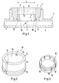
- Fig. 1 schematically shows a sight-glass arrangement 1 for a refrigerant carrying system 2.
- the sight-glass arrangement 1 comprises a housing 3 connected to nipples 4, 5 which are connected with the refrigerant carrying system 2 and form part of the refrigerant system 2, for example, a duct 6 in which a schematically illustrated valve element 7, i. e. a moving part of a valve, is shown.
- the valve element 7 is used to restrict a flow of refrigerant through the duct 6.
- the sight-glass arrangement 1 comprises a sight-glass 8 which is arranged in an opening 9 in said housing 3.
- the housing 3 itself is welded, brazed, glued or screwed into the refrigerant carrying system 2 or fixed therein in another way. Sealing means which are usually used to seal the interior of the refrigerant carrying system 2 against the outside are not shown. However, they are used as far as necessary.
- a moisture indicator 10 is arranged in the opening 9.
- Fig. 2 shows this moisture indicator 10 in a perspective view.
- the moisture indicator 10 is in form of a hollow cylinder 11 having a ring shaped wall.
- the wall 12 has a radially outer side 13 and a radially inner side 14.
- the ring shaped wall 12 has a slot 15 extending over an axial length of the ring shaped wall 12. This means, that the ring shaped wall 12 can be elastically deformed in radial direction.
- a ring shaped protrusion 16 is arranged at the radially outer side 13 of the wall 12.
- the protrusion 16 is closed in circumferential direction except the slot 15.
- the protrusion 16 can have a number of sections which are separated from each other.
- the housing 3 comprises a recess 17. As can be seen in fig. 1 the protrusion 16 extends in the recess 17 thus forming a positive locking of the moisture indicator 10 in the housing 3.
- the moisture indicator 10 comprises a recess 17 and the housing 3 comprises a protrusion 16.
- the ring shaped wall 12 is elastically deformable. When it is radially compressed it tends to return to the original diameter. When the moisture indicator 10 is inserted into the housing 3 and radially deformed inwardly, it is sufficient to release the moisture indicator 10 after the protrusion 16 reaches the recess 17. The elasticity moves the protrusion 16 into the recess 17.
- Fig. 3 shows a slightly modified form of a moisture indicator 10.
- the moisture indicator 10 has a ring shaped wall 12 as well.
- this ring shaped wall 12 comprises a number of legs 18.
- the legs 18 are separated from each other by slots 19 extending only over a part of the axial length of the wall 12.
- Each leg 18 comprises at its end a protrusion 16.
- the legs 18 are elastically deformable in radial direction and tend to return to their initial position after being deformed radially.
- the moisture indicator 10 follows immediately the sight-glass 8 in a direction towards the interior of the refrigerant carrying system 2, i. e. in a direction towards the duct 6. It is preferred that the moisture indicator 10 touches the sight-glass 8. However, this is not absolutely necessary.
- At least the inner side 14 of the wall 12 is provided with moisture indicating means, for example a cobalt salt.
- the moisture indicating means change, for example, color, when the moisture content in the refrigerant in duct 6 varies.
- the inner side 14 is visible through the sight-glass 8.
- the moisture indicator 10 can have an axial length which is sufficient to make the area of the inner side 14 large enough so that an operator looking though the sight-glass 8 can reliably recognize a change in color of the moisture indicator 10.
- the moisture indicator 10 does not cover a great area of the sight-glass 8 so that the operator at the same time has a free view into the interior of the refrigerant carrying system 2. This is in particular of advantage when the operator can see a functional element, like the valve element 7. In this case, the operator can examine the movement of the movable valve element 7 to discover whether the valve element 7 works properly.
- the sight-glass 8 has a glass thickness d and the moisture indicator 10 has an axial length l.
- the axial length l corresponds to at least 80% of the glass thickness d.
- the ring shaped wall 12 has a wall thickness w and a sight-glass 8 has a diameter D.
- the wall thickness w is 15% or less of the diameter D of the sight-glass 8.
- the moisture indicator 10 is formed as a spring clip made of a plastic material, like polymer or nylon.
- the spring clip material is molded to have a "sintered" structure.
- the sintered structure forms a lot of capillaries to allow a liquid to penetrate into the moisture indicator 10.
- the moisture indicator 10 can be dipped in a liquid, for example a cobalt salt solution so that this cobalt liquid penetrates into the polymer ring.
- the moisture indicator is ready for mounting within the housing 3. This mounting is rather simple, since it is only necessary to clip the moisture indicator 10 into the housing 3.
- the cylinder 11 is centered with respect to the sight-glass 8. Therefore, an operator has the same view into the interior of the refrigerant carrying system 2 independent of a viewing angle.
Landscapes
- Engineering & Computer Science (AREA)
- Physics & Mathematics (AREA)
- Mechanical Engineering (AREA)
- Thermal Sciences (AREA)
- General Engineering & Computer Science (AREA)
- Indicating Or Recording The Presence, Absence, Or Direction Of Movement (AREA)
- Indication Of The Valve Opening Or Closing Status (AREA)
- Measuring Volume Flow (AREA)
Abstract
Description
- The invention relates to a sight-glass arrangement for a refrigerant carrying system comprising a housing, a sight-glass through which an interior of said housing is visible, said sight-glass being arranged in an opening in said housing, and a moisture indicator in form of a hollow cylinder element having a ring shaped wall.
- Such a sight-glass arrangement is known, for example, from
US 4 018 061 . The cylinder element is positioned perpendicular to the opening in the housing so that the radially outer side of the ring shaped wall faces the opening which is covered by the sight-glass. - Other solutions in the prior art show moisture indicators in form of flat paper rings covering a major part of the opening so that it is difficult to view the interior part of the system through the sight-glass, see for example
US 3 142 287 ,US 3 371 648 orUS 3 100 691 . - As it is known, a preferred form of moisture indicating means vary the color in direct relation with the variation in moisture content of the refrigerant. In order to recognize such change of the color it is necessary that the part of the moisture indicator visible through the sight-glass has a minimum size. This has the consequence that the moisture indicator covers a relative large part of the window in which the sight-glass is arranged thus preventing inspection of the interior of the housing or of the refrigerant carrying system.
- It is an object of the present invention to allow a good inspection of a refrigerant carrying system through said sight-glass.
- This object is solved with a sight-glass arrangement as described above in that said cylinder element comprises at least on a part of the radially inner side of said wall moisture indicating means and in that said radially inner side of said wall is visible through said sight-glass.
- The moisture indicating means can be, for example, a cobalt salt or cobalt salt solution applied at least to the radially inner side of the hollow cylinder forming the moisture indicator. Since this radially inner side is visible through the sight-glass the area which can change the color in dependency of the variation of moisture content of the refrigerant can in this way have a considerable size which is sufficient to allow a reliable recognition of the change of color.
- Preferably said cylinder element is centered with respect to said sight-glass. In this case the viewing angle of an operator to the moisture indicator does not play a major role. Independently of this viewing angle the operator is able to recognize a color variation of the moisture indicator or any other change of a visible appearance.
- Preferably said cylinder element follows immediately said sight-glass in a direction towards said interior part. In a particular preferred embodiment said cylinder element contacts said sight-glass so that the distance to see the radially inner wall of the cylinder element is as short as possible.
- In a preferred embodiment one of the ring shaped wall and housing comprises protrusions and the other one comprises at least one recess, said protrusion means extending in said recess. The protrusion means and the recess cooperate to fix the cylinder element in the housing with simple means. The fixing of the cylinder element in the housing defines the position of the cylinder element with respect to the sight-glass and allows for a precise alignment of the cylinder element and the sight-glass and of a distance as short as possible between the cylinder element and the sight-glass.
- Preferably said ring shaped wall is at least on a part of its axial lengths deformable in radial direction. This facilitates mounting of the moisture indicator in the housing. Before inserting the moisture indicator into the opening of the housing, it is radially slightly compressed. As soon as it is in the intended position, it can radially be expanded in order to fix it in the opening.
- Preferably said ring shaped wall has at least one slot running in a direction from one of the axial ends to the other of said axial ends. In a preferred embodiment, said slot runs parallel to a central axis of said moisture indicator. However, it is also possible that said slot runs under a predetermined angle with respect to a line parallel to said central axis. Such a slot allows for a radial deformation without affecting the material characteristics of the moisture indicator.
- In a preferred embodiment said slot ends within said ring shaped wall. In this embodiment the ring shaped wall is in a first area closed in circumferential direction and in a second area has one or more slots so that legs are formed which can be radially deformed.
- In a particular preferred embodiment said ring shaped wall comprises a pretension radially outwardly. This has the advantage that the fixation of the cylinder element in the opening is facilitated. It is just necessary to press the cylinder element into the opening under radial compression. As soon as the cylinder element has reached the desired position, it expands radially outwardly because of the pretension.
- In a preferred embodiment said sight-glass has a glass thickness and said cylinder element has an axial length corresponding to at least 80 % of said glass thickness. The axial length of the cylinder element is quite large so that the area of the cylinder element which is visible through the sight-glass and which changes the visual appearance when the moisture contents of the refrigerant various is quite considerable.
- Furthermore, it is preferred that said ring shaped wall has a wall thickness and said sight-glass has a diameter, said wall thickness being 15 % or less of said diameter. In this case the radially inner opening of the cylinder element is large enough to allow an inspection of the interior part of the refrigerant carrying system through the hollow cylinder element. At the same time, there is enough area of the hollow cylinder element visible to recognize any change of visual appearance, for example change of color.
- Preferably said cylinder element has a sintered structure with capillaries. The sinter structure will allow said moisture indicating means, for example a cobalt salt solution, to penetrate into the cylinder element and to act as a moisture sensor.
- Preferably said cylinder element is made of a polymer. In a preferred embodiment, said polymer is nylon. Said polymer can be molded to have the above mentioned "sintered" structure.
- Preferably said interior part comprises a functional element of said refrigerant carrying system, said functional element being visible through said cylindrical element. In this way the operator has a view to the functional element through the sight-glass and through the interior of the hollow cylinder element.
- Preferably said functional element is a valve having at least one movable part, said movable part being visible through said cylindrical element. In this case the operator can see how the valve works.
- Preferred examples of the invention will now be described in more detail with reference to the drawing, wherein:
- Fig. 1
- is a schematical sectional view of a sight-glass arrangement,
- Fig. 2
- is a perspective view of a moisture indicator,
- Fig. 3
- is a perspective view of another embodiment of the moisture indicator.
-
Fig. 1 schematically shows a sight-glass arrangement 1 for arefrigerant carrying system 2. The sight-glass arrangement 1 comprises ahousing 3 connected tonipples 4, 5 which are connected with the refrigerant carryingsystem 2 and form part of therefrigerant system 2, for example, aduct 6 in which a schematically illustratedvalve element 7, i. e. a moving part of a valve, is shown. Thevalve element 7 is used to restrict a flow of refrigerant through theduct 6. - The sight-glass arrangement 1 comprises a sight-
glass 8 which is arranged in anopening 9 in saidhousing 3. Thehousing 3 itself is welded, brazed, glued or screwed into the refrigerant carryingsystem 2 or fixed therein in another way. Sealing means which are usually used to seal the interior of the refrigerant carryingsystem 2 against the outside are not shown. However, they are used as far as necessary. - A
moisture indicator 10 is arranged in theopening 9.Fig. 2 shows thismoisture indicator 10 in a perspective view. Themoisture indicator 10 is in form of a hollow cylinder 11 having a ring shaped wall. Thewall 12 has a radiallyouter side 13 and a radiallyinner side 14. Furthermore, the ring shapedwall 12 has aslot 15 extending over an axial length of the ring shapedwall 12. This means, that the ring shapedwall 12 can be elastically deformed in radial direction. - A ring shaped
protrusion 16 is arranged at the radiallyouter side 13 of thewall 12. In the present embodiment, theprotrusion 16 is closed in circumferential direction except theslot 15. However, theprotrusion 16 can have a number of sections which are separated from each other. - The
housing 3 comprises arecess 17. As can be seen infig. 1 theprotrusion 16 extends in therecess 17 thus forming a positive locking of themoisture indicator 10 in thehousing 3. - It is of course possible, that the
moisture indicator 10 comprises arecess 17 and thehousing 3 comprises aprotrusion 16. - In order to facilitate the mounting of the
moisture indicator 10 in thehousing 3, the ring shapedwall 12 is elastically deformable. When it is radially compressed it tends to return to the original diameter. When themoisture indicator 10 is inserted into thehousing 3 and radially deformed inwardly, it is sufficient to release themoisture indicator 10 after theprotrusion 16 reaches therecess 17. The elasticity moves theprotrusion 16 into therecess 17. -
Fig. 3 shows a slightly modified form of amoisture indicator 10. Themoisture indicator 10 has a ring shapedwall 12 as well. However, this ring shapedwall 12 comprises a number oflegs 18. Thelegs 18 are separated from each other byslots 19 extending only over a part of the axial length of thewall 12. Eachleg 18 comprises at its end aprotrusion 16. - The
legs 18 are elastically deformable in radial direction and tend to return to their initial position after being deformed radially. - As can be seen in
fig. 1 themoisture indicator 10 follows immediately the sight-glass 8 in a direction towards the interior of therefrigerant carrying system 2, i. e. in a direction towards theduct 6. It is preferred that themoisture indicator 10 touches the sight-glass 8. However, this is not absolutely necessary. - At least the
inner side 14 of thewall 12 is provided with moisture indicating means, for example a cobalt salt. The moisture indicating means change, for example, color, when the moisture content in the refrigerant induct 6 varies. - The
inner side 14 is visible through the sight-glass 8. Themoisture indicator 10 can have an axial length which is sufficient to make the area of theinner side 14 large enough so that an operator looking though the sight-glass 8 can reliably recognize a change in color of themoisture indicator 10. On the other hand, themoisture indicator 10 does not cover a great area of the sight-glass 8 so that the operator at the same time has a free view into the interior of therefrigerant carrying system 2. This is in particular of advantage when the operator can see a functional element, like thevalve element 7. In this case, the operator can examine the movement of themovable valve element 7 to discover whether thevalve element 7 works properly. - The sight-
glass 8 has a glass thickness d and themoisture indicator 10 has an axial length l. The axial length l corresponds to at least 80% of the glass thickness d. - Furthermore, the ring shaped
wall 12 has a wall thickness w and a sight-glass 8 has a diameter D. The wall thickness w is 15% or less of the diameter D of the sight-glass 8. - The
moisture indicator 10 is formed as a spring clip made of a plastic material, like polymer or nylon. The spring clip material is molded to have a "sintered" structure. The sintered structure forms a lot of capillaries to allow a liquid to penetrate into themoisture indicator 10. After forming of the spring clip themoisture indicator 10 can be dipped in a liquid, for example a cobalt salt solution so that this cobalt liquid penetrates into the polymer ring. After drying of themoisture indicator 10, the moisture indicator is ready for mounting within thehousing 3. This mounting is rather simple, since it is only necessary to clip themoisture indicator 10 into thehousing 3. - After that, not only the
inner side 14 is visible through the sight-glass 8 allowing a reliable recognition of a change of color of themoisture indicator 10, but also the interior of therefrigerant carrying system 2 is visible, in particular a movable part of a functional element, like thevalve element 7. - As can be seen in
fig. 1 , the cylinder 11 is centered with respect to the sight-glass 8. Therefore, an operator has the same view into the interior of therefrigerant carrying system 2 independent of a viewing angle.
Claims (14)
- Sight-glass arrangement (1) for a refrigerant carrying system (2) comprising a housing, a sight-glass (8) through which an interior of said housing (3) is visible, said sight-glass (8) being arranged in an opening (9) in said housing (3), and a moisture indicator (10) in form of a hollow cylinder element (11) having a ring shaped wall (12), characterized in that said cylinder element (11) comprises at least on a part of the radially inner side (14) of said wall (12) moisture indicating means and in that said radially inner side (14) of said wall is visible through said sight-glass (8).
- Sight-glass arrangement according to claim 1, characterized in that said cylinder element (11) is centered with respect to said sight-glass (8).
- Sight-glass arrangement according to claim 1 or 2, characterized in that said cylinder element (11) follows immediately said sight-glass (8) in a direction towards said interior part (6).
- Sight-glass arrangement according to any of claims 1 to 3, characterized in that one of the ring shaped wall (12) and housing (3) comprises protrusion means (16) and the other one comprises at least one recess (17), said protrusion means (16) extending in said recess (17).
- Sight-glass arrangement according to any of claims 1 to 4, characterized in that said ring shaped wall (12) is at least on a part of its axial length deformable in radial direction.
- Sight-glass arrangement according to any of claims 1 to 5, characterized in that said ring shaped wall (12) has at least one slot (15, 19) running in a direction from one of the axial ends to the other of said axial ends.
- Sight-glass arrangement according to claim 6, characterized in that said slot (19) ends within said ring shaped wall (12).
- Sight-glass arrangement according to claim 6 or 7, characterized in that said ring shaped wall (12) comprises a pretension radially outwardly.
- Sight-glass arrangement according to any of claims 1 to 8, characterized in that said sight-glass (8) has a glass thickness (d) and said cylinder element (11) has an axial length (l) corresponding to at least 80% of said glass thickness (d).
- Sight-glass arrangement according to any of claims 1 to 9, characterized in that said ring shaped wall (12) has a wall thickness (w) and said sight-glass (8) has a diameter (D), said wall thickness (w) being 15% or less of said diameter (D).
- Sight-glass arrangement according to any of claims 1 to 10, characterized in that said cylinder element (11) has a sintered structure with capillaries.
- Sight-glass arrangement according to claim 11, characterized in that said cylinder element (11) is made of a polymer.
- Sight-glass arrangement according to any of claims 1 to 12, characterized in that said interior part (6) comprises a functional element (7) of said refrigerant carrying system (2), said functional element (7) being visible through said cylindrical element (11).
- Sight-glass arrangement according to claim 13, characterized in that said functional element (7) is a valve having at least one movable part, said movable part being visible through said cylindrical element (11).
Priority Applications (1)
| Application Number | Priority Date | Filing Date | Title |
|---|---|---|---|
| EP14189123.4A EP3009772B1 (en) | 2014-10-16 | 2014-10-16 | Sight-glass arrangement for a refrigerant carrying system |
Applications Claiming Priority (1)
| Application Number | Priority Date | Filing Date | Title |
|---|---|---|---|
| EP14189123.4A EP3009772B1 (en) | 2014-10-16 | 2014-10-16 | Sight-glass arrangement for a refrigerant carrying system |
Publications (2)
| Publication Number | Publication Date |
|---|---|
| EP3009772A1 true EP3009772A1 (en) | 2016-04-20 |
| EP3009772B1 EP3009772B1 (en) | 2017-05-17 |
Family
ID=51753048
Family Applications (1)
| Application Number | Title | Priority Date | Filing Date |
|---|---|---|---|
| EP14189123.4A Not-in-force EP3009772B1 (en) | 2014-10-16 | 2014-10-16 | Sight-glass arrangement for a refrigerant carrying system |
Country Status (1)
| Country | Link |
|---|---|
| EP (1) | EP3009772B1 (en) |
Cited By (1)
| Publication number | Priority date | Publication date | Assignee | Title |
|---|---|---|---|---|
| US20190390885A1 (en) * | 2018-06-22 | 2019-12-26 | Emerson Climate Technologies Retail Solutions, Inc. | Systems And Methods For Optical Detection Of Refrigeration System Abnormalities |
Citations (6)
| Publication number | Priority date | Publication date | Assignee | Title |
|---|---|---|---|---|
| GB887404A (en) * | 1959-11-17 | 1962-01-17 | Ansul Chemical Co | Moisture indicator housing |
| US3100691A (en) | 1959-03-12 | 1963-08-13 | Henry Valve Co | Liquid indicator with moisture indication means |
| US3142287A (en) | 1961-12-22 | 1964-07-28 | Henry Valve Co | Refrigerant moisture-liquid indicator assembly and cap unit therefor |
| US3371648A (en) | 1966-03-24 | 1968-03-05 | Mueller Brass Co | Liquid indicator |
| DE2358654A1 (en) * | 1973-11-24 | 1975-05-28 | Hansa Metallwerke Ag | Indicator for liquid refrigerant - has glass ball beneath sight glass, and indicators for moisture and acid content |
| US4018061A (en) | 1974-11-27 | 1977-04-19 | General Motors Corporation | Moisture indicator |
-
2014
- 2014-10-16 EP EP14189123.4A patent/EP3009772B1/en not_active Not-in-force
Patent Citations (6)
| Publication number | Priority date | Publication date | Assignee | Title |
|---|---|---|---|---|
| US3100691A (en) | 1959-03-12 | 1963-08-13 | Henry Valve Co | Liquid indicator with moisture indication means |
| GB887404A (en) * | 1959-11-17 | 1962-01-17 | Ansul Chemical Co | Moisture indicator housing |
| US3142287A (en) | 1961-12-22 | 1964-07-28 | Henry Valve Co | Refrigerant moisture-liquid indicator assembly and cap unit therefor |
| US3371648A (en) | 1966-03-24 | 1968-03-05 | Mueller Brass Co | Liquid indicator |
| DE2358654A1 (en) * | 1973-11-24 | 1975-05-28 | Hansa Metallwerke Ag | Indicator for liquid refrigerant - has glass ball beneath sight glass, and indicators for moisture and acid content |
| US4018061A (en) | 1974-11-27 | 1977-04-19 | General Motors Corporation | Moisture indicator |
Cited By (2)
| Publication number | Priority date | Publication date | Assignee | Title |
|---|---|---|---|---|
| US20190390885A1 (en) * | 2018-06-22 | 2019-12-26 | Emerson Climate Technologies Retail Solutions, Inc. | Systems And Methods For Optical Detection Of Refrigeration System Abnormalities |
| US11085683B2 (en) * | 2018-06-22 | 2021-08-10 | Emerson Climate Technologies Retail Solutions, Inc. | Systems and methods for optical detection of refrigeration system abnormalities |
Also Published As
| Publication number | Publication date |
|---|---|
| EP3009772B1 (en) | 2017-05-17 |
Similar Documents
| Publication | Publication Date | Title |
|---|---|---|
| US9233652B2 (en) | Closure plug | |
| US10107433B2 (en) | Quick connector assembly and method of establishing and ensuring a fluid-tight connection between conduits | |
| US10550967B2 (en) | Connector assembly | |
| US20100156092A1 (en) | Device for axially connecting an external pipe section to a coaxial peg or an internal pipe section that engages in said section | |
| EP2341321A2 (en) | Snap-fit sensor assembly | |
| RU2599439C2 (en) | Element, preferably closure element for inserting into bore in component | |
| US10060776B2 (en) | Differential pressure sensor, and filtration device used therewith | |
| EP3009772B1 (en) | Sight-glass arrangement for a refrigerant carrying system | |
| US20200030724A1 (en) | Filter device | |
| RU2018146806A (en) | CAP ASSEMBLY FOR DEVICE OF DELIVERY OF MEDICINES AND METHOD OF ASSEMBLY OF CAP ASSEMBLY | |
| EP2811199A1 (en) | Sealing assembly adapted to be inserted between two relatively slidable members | |
| CN107869647B (en) | Overpressure indicator and its kit and method of setting its intervention pressure | |
| BRPI0608069A2 (en) | manufacture of casing for use in water desalination and liquid filtration | |
| CN208347964U (en) | sensor unit | |
| US20150233414A1 (en) | Terminal for a motion transmitting remote control assembly | |
| EP2853342A2 (en) | Switch target arrangement | |
| US9945402B2 (en) | Internal position sensor | |
| KR102555072B1 (en) | Instrumented bearing and manufacturing process of such instrumented bearing | |
| US11106962B2 (en) | Apparatus for arranging an electronic data carrier on a component of a fluidic system | |
| US12158170B2 (en) | Tool-free front attachment fitting | |
| JP2015141070A (en) | humidity sensor | |
| DE202013007490U1 (en) | Temperature sensor for a fluid | |
| GB2525027A (en) | Marking gauge | |
| EP3203203A1 (en) | Sensor device | |
| US10309563B2 (en) | Drive unit, internal combustion engine, spacer element for a fluid line arrangement, and tool kit for mounting a spacer element |
Legal Events
| Date | Code | Title | Description |
|---|---|---|---|
| PUAI | Public reference made under article 153(3) epc to a published international application that has entered the european phase |
Free format text: ORIGINAL CODE: 0009012 |
|
| AK | Designated contracting states |
Kind code of ref document: A1 Designated state(s): AL AT BE BG CH CY CZ DE DK EE ES FI FR GB GR HR HU IE IS IT LI LT LU LV MC MK MT NL NO PL PT RO RS SE SI SK SM TR |
|
| AX | Request for extension of the european patent |
Extension state: BA ME |
|
| 17P | Request for examination filed |
Effective date: 20161013 |
|
| RBV | Designated contracting states (corrected) |
Designated state(s): AL AT BE BG CH CY CZ DE DK EE ES FI FR GB GR HR HU IE IS IT LI LT LU LV MC MK MT NL NO PL PT RO RS SE SI SK SM TR |
|
| GRAP | Despatch of communication of intention to grant a patent |
Free format text: ORIGINAL CODE: EPIDOSNIGR1 |
|
| INTG | Intention to grant announced |
Effective date: 20161223 |
|
| GRAJ | Information related to disapproval of communication of intention to grant by the applicant or resumption of examination proceedings by the epo deleted |
Free format text: ORIGINAL CODE: EPIDOSDIGR1 |
|
| GRAP | Despatch of communication of intention to grant a patent |
Free format text: ORIGINAL CODE: EPIDOSNIGR1 |
|
| INTC | Intention to grant announced (deleted) | ||
| INTG | Intention to grant announced |
Effective date: 20170220 |
|
| GRAS | Grant fee paid |
Free format text: ORIGINAL CODE: EPIDOSNIGR3 |
|
| GRAA | (expected) grant |
Free format text: ORIGINAL CODE: 0009210 |
|
| AK | Designated contracting states |
Kind code of ref document: B1 Designated state(s): AL AT BE BG CH CY CZ DE DK EE ES FI FR GB GR HR HU IE IS IT LI LT LU LV MC MK MT NL NO PL PT RO RS SE SI SK SM TR |
|
| REG | Reference to a national code |
Ref country code: GB Ref legal event code: FG4D |
|
| REG | Reference to a national code |
Ref country code: CH Ref legal event code: EP |
|
| REG | Reference to a national code |
Ref country code: IE Ref legal event code: FG4D |
|
| REG | Reference to a national code |
Ref country code: AT Ref legal event code: REF Ref document number: 894840 Country of ref document: AT Kind code of ref document: T Effective date: 20170615 |
|
| REG | Reference to a national code |
Ref country code: DE Ref legal event code: R096 Ref document number: 602014009868 Country of ref document: DE |
|
| REG | Reference to a national code |
Ref country code: NL Ref legal event code: MP Effective date: 20170517 |
|
| REG | Reference to a national code |
Ref country code: LT Ref legal event code: MG4D |
|
| REG | Reference to a national code |
Ref country code: AT Ref legal event code: MK05 Ref document number: 894840 Country of ref document: AT Kind code of ref document: T Effective date: 20170517 |
|
| PG25 | Lapsed in a contracting state [announced via postgrant information from national office to epo] |
Ref country code: ES Free format text: LAPSE BECAUSE OF FAILURE TO SUBMIT A TRANSLATION OF THE DESCRIPTION OR TO PAY THE FEE WITHIN THE PRESCRIBED TIME-LIMIT Effective date: 20170517 Ref country code: GR Free format text: LAPSE BECAUSE OF FAILURE TO SUBMIT A TRANSLATION OF THE DESCRIPTION OR TO PAY THE FEE WITHIN THE PRESCRIBED TIME-LIMIT Effective date: 20170818 Ref country code: LT Free format text: LAPSE BECAUSE OF FAILURE TO SUBMIT A TRANSLATION OF THE DESCRIPTION OR TO PAY THE FEE WITHIN THE PRESCRIBED TIME-LIMIT Effective date: 20170517 Ref country code: HR Free format text: LAPSE BECAUSE OF FAILURE TO SUBMIT A TRANSLATION OF THE DESCRIPTION OR TO PAY THE FEE WITHIN THE PRESCRIBED TIME-LIMIT Effective date: 20170517 Ref country code: FI Free format text: LAPSE BECAUSE OF FAILURE TO SUBMIT A TRANSLATION OF THE DESCRIPTION OR TO PAY THE FEE WITHIN THE PRESCRIBED TIME-LIMIT Effective date: 20170517 Ref country code: NO Free format text: LAPSE BECAUSE OF FAILURE TO SUBMIT A TRANSLATION OF THE DESCRIPTION OR TO PAY THE FEE WITHIN THE PRESCRIBED TIME-LIMIT Effective date: 20170817 Ref country code: AT Free format text: LAPSE BECAUSE OF FAILURE TO SUBMIT A TRANSLATION OF THE DESCRIPTION OR TO PAY THE FEE WITHIN THE PRESCRIBED TIME-LIMIT Effective date: 20170517 |
|
| PG25 | Lapsed in a contracting state [announced via postgrant information from national office to epo] |
Ref country code: NL Free format text: LAPSE BECAUSE OF FAILURE TO SUBMIT A TRANSLATION OF THE DESCRIPTION OR TO PAY THE FEE WITHIN THE PRESCRIBED TIME-LIMIT Effective date: 20170517 Ref country code: IS Free format text: LAPSE BECAUSE OF FAILURE TO SUBMIT A TRANSLATION OF THE DESCRIPTION OR TO PAY THE FEE WITHIN THE PRESCRIBED TIME-LIMIT Effective date: 20170917 Ref country code: LV Free format text: LAPSE BECAUSE OF FAILURE TO SUBMIT A TRANSLATION OF THE DESCRIPTION OR TO PAY THE FEE WITHIN THE PRESCRIBED TIME-LIMIT Effective date: 20170517 Ref country code: RS Free format text: LAPSE BECAUSE OF FAILURE TO SUBMIT A TRANSLATION OF THE DESCRIPTION OR TO PAY THE FEE WITHIN THE PRESCRIBED TIME-LIMIT Effective date: 20170517 Ref country code: BG Free format text: LAPSE BECAUSE OF FAILURE TO SUBMIT A TRANSLATION OF THE DESCRIPTION OR TO PAY THE FEE WITHIN THE PRESCRIBED TIME-LIMIT Effective date: 20170817 Ref country code: SE Free format text: LAPSE BECAUSE OF FAILURE TO SUBMIT A TRANSLATION OF THE DESCRIPTION OR TO PAY THE FEE WITHIN THE PRESCRIBED TIME-LIMIT Effective date: 20170517 Ref country code: PL Free format text: LAPSE BECAUSE OF FAILURE TO SUBMIT A TRANSLATION OF THE DESCRIPTION OR TO PAY THE FEE WITHIN THE PRESCRIBED TIME-LIMIT Effective date: 20170517 |
|
| PG25 | Lapsed in a contracting state [announced via postgrant information from national office to epo] |
Ref country code: SK Free format text: LAPSE BECAUSE OF FAILURE TO SUBMIT A TRANSLATION OF THE DESCRIPTION OR TO PAY THE FEE WITHIN THE PRESCRIBED TIME-LIMIT Effective date: 20170517 Ref country code: RO Free format text: LAPSE BECAUSE OF FAILURE TO SUBMIT A TRANSLATION OF THE DESCRIPTION OR TO PAY THE FEE WITHIN THE PRESCRIBED TIME-LIMIT Effective date: 20170517 Ref country code: CZ Free format text: LAPSE BECAUSE OF FAILURE TO SUBMIT A TRANSLATION OF THE DESCRIPTION OR TO PAY THE FEE WITHIN THE PRESCRIBED TIME-LIMIT Effective date: 20170517 Ref country code: EE Free format text: LAPSE BECAUSE OF FAILURE TO SUBMIT A TRANSLATION OF THE DESCRIPTION OR TO PAY THE FEE WITHIN THE PRESCRIBED TIME-LIMIT Effective date: 20170517 Ref country code: DK Free format text: LAPSE BECAUSE OF FAILURE TO SUBMIT A TRANSLATION OF THE DESCRIPTION OR TO PAY THE FEE WITHIN THE PRESCRIBED TIME-LIMIT Effective date: 20170517 |
|
| REG | Reference to a national code |
Ref country code: DE Ref legal event code: R097 Ref document number: 602014009868 Country of ref document: DE |
|
| PG25 | Lapsed in a contracting state [announced via postgrant information from national office to epo] |
Ref country code: IT Free format text: LAPSE BECAUSE OF FAILURE TO SUBMIT A TRANSLATION OF THE DESCRIPTION OR TO PAY THE FEE WITHIN THE PRESCRIBED TIME-LIMIT Effective date: 20170517 Ref country code: SM Free format text: LAPSE BECAUSE OF FAILURE TO SUBMIT A TRANSLATION OF THE DESCRIPTION OR TO PAY THE FEE WITHIN THE PRESCRIBED TIME-LIMIT Effective date: 20170517 |
|
| PLBE | No opposition filed within time limit |
Free format text: ORIGINAL CODE: 0009261 |
|
| STAA | Information on the status of an ep patent application or granted ep patent |
Free format text: STATUS: NO OPPOSITION FILED WITHIN TIME LIMIT |
|
| 26N | No opposition filed |
Effective date: 20180220 |
|
| REG | Reference to a national code |
Ref country code: DE Ref legal event code: R119 Ref document number: 602014009868 Country of ref document: DE |
|
| PG25 | Lapsed in a contracting state [announced via postgrant information from national office to epo] |
Ref country code: MC Free format text: LAPSE BECAUSE OF FAILURE TO SUBMIT A TRANSLATION OF THE DESCRIPTION OR TO PAY THE FEE WITHIN THE PRESCRIBED TIME-LIMIT Effective date: 20170517 Ref country code: SI Free format text: LAPSE BECAUSE OF FAILURE TO SUBMIT A TRANSLATION OF THE DESCRIPTION OR TO PAY THE FEE WITHIN THE PRESCRIBED TIME-LIMIT Effective date: 20170517 |
|
| REG | Reference to a national code |
Ref country code: CH Ref legal event code: PL |
|
| REG | Reference to a national code |
Ref country code: IE Ref legal event code: MM4A |
|
| REG | Reference to a national code |
Ref country code: FR Ref legal event code: ST Effective date: 20180629 |
|
| PG25 | Lapsed in a contracting state [announced via postgrant information from national office to epo] |
Ref country code: CH Free format text: LAPSE BECAUSE OF NON-PAYMENT OF DUE FEES Effective date: 20171031 Ref country code: LU Free format text: LAPSE BECAUSE OF NON-PAYMENT OF DUE FEES Effective date: 20171016 Ref country code: DE Free format text: LAPSE BECAUSE OF NON-PAYMENT OF DUE FEES Effective date: 20180501 Ref country code: LI Free format text: LAPSE BECAUSE OF NON-PAYMENT OF DUE FEES Effective date: 20171031 |
|
| REG | Reference to a national code |
Ref country code: BE Ref legal event code: MM Effective date: 20171031 |
|
| PG25 | Lapsed in a contracting state [announced via postgrant information from national office to epo] |
Ref country code: BE Free format text: LAPSE BECAUSE OF NON-PAYMENT OF DUE FEES Effective date: 20171031 Ref country code: FR Free format text: LAPSE BECAUSE OF NON-PAYMENT OF DUE FEES Effective date: 20171031 |
|
| PG25 | Lapsed in a contracting state [announced via postgrant information from national office to epo] |
Ref country code: MT Free format text: LAPSE BECAUSE OF NON-PAYMENT OF DUE FEES Effective date: 20171016 |
|
| PG25 | Lapsed in a contracting state [announced via postgrant information from national office to epo] |
Ref country code: IE Free format text: LAPSE BECAUSE OF NON-PAYMENT OF DUE FEES Effective date: 20171016 |
|
| GBPC | Gb: european patent ceased through non-payment of renewal fee |
Effective date: 20181016 |
|
| PG25 | Lapsed in a contracting state [announced via postgrant information from national office to epo] |
Ref country code: HU Free format text: LAPSE BECAUSE OF FAILURE TO SUBMIT A TRANSLATION OF THE DESCRIPTION OR TO PAY THE FEE WITHIN THE PRESCRIBED TIME-LIMIT; INVALID AB INITIO Effective date: 20141016 |
|
| PG25 | Lapsed in a contracting state [announced via postgrant information from national office to epo] |
Ref country code: CY Free format text: LAPSE BECAUSE OF FAILURE TO SUBMIT A TRANSLATION OF THE DESCRIPTION OR TO PAY THE FEE WITHIN THE PRESCRIBED TIME-LIMIT Effective date: 20170517 Ref country code: GB Free format text: LAPSE BECAUSE OF NON-PAYMENT OF DUE FEES Effective date: 20181016 |
|
| PG25 | Lapsed in a contracting state [announced via postgrant information from national office to epo] |
Ref country code: MK Free format text: LAPSE BECAUSE OF FAILURE TO SUBMIT A TRANSLATION OF THE DESCRIPTION OR TO PAY THE FEE WITHIN THE PRESCRIBED TIME-LIMIT Effective date: 20170517 |
|
| PG25 | Lapsed in a contracting state [announced via postgrant information from national office to epo] |
Ref country code: TR Free format text: LAPSE BECAUSE OF FAILURE TO SUBMIT A TRANSLATION OF THE DESCRIPTION OR TO PAY THE FEE WITHIN THE PRESCRIBED TIME-LIMIT Effective date: 20170517 |
|
| PG25 | Lapsed in a contracting state [announced via postgrant information from national office to epo] |
Ref country code: PT Free format text: LAPSE BECAUSE OF FAILURE TO SUBMIT A TRANSLATION OF THE DESCRIPTION OR TO PAY THE FEE WITHIN THE PRESCRIBED TIME-LIMIT Effective date: 20170517 |
|
| PG25 | Lapsed in a contracting state [announced via postgrant information from national office to epo] |
Ref country code: AL Free format text: LAPSE BECAUSE OF FAILURE TO SUBMIT A TRANSLATION OF THE DESCRIPTION OR TO PAY THE FEE WITHIN THE PRESCRIBED TIME-LIMIT Effective date: 20170517 |