EP3009712A1 - Multi-stages automatic transmission for vehicle - Google Patents
Multi-stages automatic transmission for vehicle Download PDFInfo
- Publication number
- EP3009712A1 EP3009712A1 EP15168095.6A EP15168095A EP3009712A1 EP 3009712 A1 EP3009712 A1 EP 3009712A1 EP 15168095 A EP15168095 A EP 15168095A EP 3009712 A1 EP3009712 A1 EP 3009712A1
- Authority
- EP
- European Patent Office
- Prior art keywords
- rotation element
- planetary gear
- gear set
- carrier
- clutch
- Prior art date
- Legal status (The legal status is an assumption and is not a legal conclusion. Google has not performed a legal analysis and makes no representation as to the accuracy of the status listed.)
- Granted
Links
Images


Classifications
-
- F—MECHANICAL ENGINEERING; LIGHTING; HEATING; WEAPONS; BLASTING
- F16—ENGINEERING ELEMENTS AND UNITS; GENERAL MEASURES FOR PRODUCING AND MAINTAINING EFFECTIVE FUNCTIONING OF MACHINES OR INSTALLATIONS; THERMAL INSULATION IN GENERAL
- F16H—GEARING
- F16H3/00—Toothed gearings for conveying rotary motion with variable gear ratio or for reversing rotary motion
- F16H3/44—Toothed gearings for conveying rotary motion with variable gear ratio or for reversing rotary motion using gears having orbital motion
-
- F—MECHANICAL ENGINEERING; LIGHTING; HEATING; WEAPONS; BLASTING
- F16—ENGINEERING ELEMENTS AND UNITS; GENERAL MEASURES FOR PRODUCING AND MAINTAINING EFFECTIVE FUNCTIONING OF MACHINES OR INSTALLATIONS; THERMAL INSULATION IN GENERAL
- F16H—GEARING
- F16H3/00—Toothed gearings for conveying rotary motion with variable gear ratio or for reversing rotary motion
- F16H3/44—Toothed gearings for conveying rotary motion with variable gear ratio or for reversing rotary motion using gears having orbital motion
- F16H3/62—Gearings having three or more central gears
- F16H3/66—Gearings having three or more central gears composed of a number of gear trains without drive passing from one train to another
-
- F—MECHANICAL ENGINEERING; LIGHTING; HEATING; WEAPONS; BLASTING
- F16—ENGINEERING ELEMENTS AND UNITS; GENERAL MEASURES FOR PRODUCING AND MAINTAINING EFFECTIVE FUNCTIONING OF MACHINES OR INSTALLATIONS; THERMAL INSULATION IN GENERAL
- F16H—GEARING
- F16H3/00—Toothed gearings for conveying rotary motion with variable gear ratio or for reversing rotary motion
- F16H3/44—Toothed gearings for conveying rotary motion with variable gear ratio or for reversing rotary motion using gears having orbital motion
- F16H3/62—Gearings having three or more central gears
-
- F—MECHANICAL ENGINEERING; LIGHTING; HEATING; WEAPONS; BLASTING
- F16—ENGINEERING ELEMENTS AND UNITS; GENERAL MEASURES FOR PRODUCING AND MAINTAINING EFFECTIVE FUNCTIONING OF MACHINES OR INSTALLATIONS; THERMAL INSULATION IN GENERAL
- F16H—GEARING
- F16H2200/00—Transmissions for multiple ratios
- F16H2200/003—Transmissions for multiple ratios characterised by the number of forward speeds
- F16H2200/0069—Transmissions for multiple ratios characterised by the number of forward speeds the gear ratios comprising ten forward speeds
-
- F—MECHANICAL ENGINEERING; LIGHTING; HEATING; WEAPONS; BLASTING
- F16—ENGINEERING ELEMENTS AND UNITS; GENERAL MEASURES FOR PRODUCING AND MAINTAINING EFFECTIVE FUNCTIONING OF MACHINES OR INSTALLATIONS; THERMAL INSULATION IN GENERAL
- F16H—GEARING
- F16H2200/00—Transmissions for multiple ratios
- F16H2200/20—Transmissions using gears with orbital motion
- F16H2200/2002—Transmissions using gears with orbital motion characterised by the number of sets of orbital gears
- F16H2200/2012—Transmissions using gears with orbital motion characterised by the number of sets of orbital gears with four sets of orbital gears
-
- F—MECHANICAL ENGINEERING; LIGHTING; HEATING; WEAPONS; BLASTING
- F16—ENGINEERING ELEMENTS AND UNITS; GENERAL MEASURES FOR PRODUCING AND MAINTAINING EFFECTIVE FUNCTIONING OF MACHINES OR INSTALLATIONS; THERMAL INSULATION IN GENERAL
- F16H—GEARING
- F16H2200/00—Transmissions for multiple ratios
- F16H2200/20—Transmissions using gears with orbital motion
- F16H2200/203—Transmissions using gears with orbital motion characterised by the engaging friction means not of the freewheel type, e.g. friction clutches or brakes
- F16H2200/2046—Transmissions using gears with orbital motion characterised by the engaging friction means not of the freewheel type, e.g. friction clutches or brakes with six engaging means
Definitions
- the present invention relates to a multi-stages automatic transmission for a vehicle, and more particularly, to a multi-stages automatic transmission for a vehicle equipped with a gear train embodying 10 forward speeds and 1 reverse speed with gear efficiency 98.6%.
- Appropriate power train technologies corresponding to the need have been provided, including an engine downsizing technology and a multi-staging technology of an automatic transmission.
- the engine downsizing has merits of reducing weight and improving fuel efficiency, and particularly, the automatic transmission multi-staging has merits of securing drivability and competitiveness of fuel efficiency at the same time through design of an excellent gear ratio in terms of power performance and fuel efficiency by using more shift stages as compared to a 4-speed (or 5-speed), and 1 reverse speed automatic transmission.
- An instance of such multi-staging of the automatic transmission includes an 8 forward speed and 1 reverse speed automatic transmission by combining three planetary gear sets and six friction elements, and 9 forward speed and 1 reverse speed automatic transmission by combining four planetary gear sets, four friction elements and two dog clutches.
- Various aspects of the present invention are directed to providing a multi-stages automatic transmission for a vehicle that improves drivability of the vehicle using an operation point of a low RPM range of an engine by implementing 10 forward speeds and 1 reverse speed with the gear train using four planetary gear sets, four clutches and two brakes, and especially, achieves better fuel efficiency improvement with the gear train implementing gear efficiency of 98.6%.
- a multi-stages automatic transmission for a vehicle may include first, second, third and fourth planetary gear sets each including first, second and third rotation elements, respectively, and friction members including first, second, third and fourth clutches and first and second brakes, in which an input shaft may be fixedly connected to the second rotation element of the first planetary gear set and the second rotation element of the second planetary gear set, the third rotation element of the first planetary gear set may be fixedly connected to the second rotation element of the third planetary gear set, the first rotation element of the second planetary gear set may be fixedly connected to the first rotation element of the fourth planetary gear set, the first rotation element of the third planetary gear set may be fixedly connected to the first rotation element of the fourth planetary gear set, and an output shaft may be fixedly connected to the second rotation element of the fourth planetary gear set.
- the first break may fix the first rotation element of the first planetary gear set
- the second break may fix the third rotation element of the fourth planetary gear set
- the first clutch may connect the second rotation element of the second planetary gear set with the third rotation element of the third planetary gear set
- the second clutch may connect the first rotation element of the third planetary gear set with the third rotation element of the third planetary gear set
- the third clutch may connect the third rotation element of the first planetary gear set with the third rotation element of the fourth planetary gear set
- the fourth clutch may connect the third rotation element of the second planetary gear set with the output shaft.
- the first planetary gear set and the second planetary gear set may comprise a first complex planetary gear set
- the third planetary gear set and the fourth planetary gear set comprise a second complex planetary gear set
- the first planetary gear set may include a first sun gear as the first rotation element, a first carrier as the second rotation element, and a first ring gear as the third rotation element
- the second planetary gear set may include a second sun gear as the first rotation element, a second carrier as the second rotation element, and a second ring gear as the third rotation element
- the third planetary gear set may include a third sun gear as the first rotation element, a third carrier as the second rotation element, and a third ring gear as the third rotation element
- the fourth planetary gear set may include a fourth sun gear as the first rotation element, a fourth carrier as the second rotation element, and a fourth ring gear as the third rotation element.
- the first sun gear among the first sun gear, the first carrier and the first ring gear of the first planetary gear set may be fixed with the first brake, the first carrier may be continuously fixed with the input shaft to connect with the second carrier, and the first ring gear may be fixedly connected to the third carrier and selectively connected to the second brake through the third clutch.
- the second sun gear among the second sun gear, the second carrier and the second ring gear of the second planetary gear set may be continuously fixed with the fourth sun gear
- the second carrier may be continuously fixed to the input shaft and selectively connected with the third ring gear through the first clutch
- the second ring gear may be selectively connected with the output shaft through the fourth clutch.
- the third sun gear among the third sun gear, the third carrier, and the third ring gear of the third planetary gear set may be continuously fixed with the fourth sun gear, the third carrier may be selectively connected with the fourth ring gear through the third clutch, and the third ring gear may be selectively connected with the third carrier through the second clutch.
- the fourth sun gear among the fourth sun gear, the fourth carrier, and the fourth ring gear of the fourth planetary gear set may be continuously fixed with the third sun gear, the fourth carrier may be fixedly connected with the output shaft, and the fourth ring gear may be fixed with the second brake and selectively connected with the first ring gear through the third clutch.
- the multi-stages automatic transmission of the present invention implements 10 forward speeds and 1 reverse speed with the gear train using the four planetary gear sets, the four clutches, and the two brakes, thereby realizing an effect that the elements for a transmission implementing 10 forward speeds and 1 reverse speed are minimized.
- the multi-stages automatic transmission of the present invention has an effect that simultaneously achieves the fuel efficiency improvement according to forward 10-speeds by the structure of the optimized gear train with gear efficiency of 98.6% and improves drivability of the vehicle by using an operation point of a low RPM range of the engine.
- the present invention has an effect of responding quickly to a market for the multi-stages automatic transmissions having an increased mounting ratio of more than 7-speed automatic transmission.
- vehicle or “vehicular” or other similar terms as used herein is inclusive of motor vehicles in general such as passenger automobiles including sports utility vehicles (SUV), buses, trucks, various commercial vehicles, watercraft including a variety of boats and ships, aircraft, and the like, and includes hybrid vehicles, electric vehicles, plug-in hybrid electric vehicles, hydrogen-powered vehicles and other alternative fuel vehicles (e.g., fuel derived from resources other than petroleum).
- a hybrid vehicle is a vehicle that has two or more sources of power, for example, both gasoline-powered and electric-powered vehicles.
- FIG. 1 shows a configuration of a gear train of a multi-stages automatic transmission for a vehicle according to the present invention.
- an input at a gear train is achieved through an input shaft IN as an input member and an output gets out to an output shaft OUT as an output member.
- the input shaft IN means a turbine shaft of a torque convert into which the rotational power from an engine crank shaft is torque-converted and then inputted.
- the output shaft OUT is connected to a well-known differential device rotating driving wheels.
- the gear train may include four planetary gear sets 10, 20, 30 and 40 disposed in the same shaft line, a clutch set 50 including a first, second, third and fourth clutches C1, C2, C3, C4, a brake set 60 including first and second brakes B1, B2, thereby embodying a forward 10-speed and a reverse 1-speed through the selective operations of four planetary gear sets and six friction members.
- the four planetary gear sets 10, 20, 30, 40 may be classified into a first complex planetary gear device including the first planetary gear set 10 and the second planetary gear set 20 and a second complex planetary device including the third planetary gear set 30 and the fourth planetary gear set 40.
- the first complex planetary gear device and the second complex planetary gear device may be connected each other through at least one continuous combination route and through at least two selective combination route.
- a first rotation element of the first planetary gear set 10 may be fixed with a first brake B1
- a second rotation element of the first planetary gear set 10 may be continuously fixed with the input shaft IN to fixedly connect to a second rotation element of the second planetary gear set 20
- a third rotation element of the first planetary gear set 10 may be fixedly connected to a second rotation element of the third planetary gear set 30 and may be selectively connected to the second brake B2 through the third clutch C3.
- a first rotation element of the second planetary gear set 20 may be continuously fixed with a first rotation element of the fourth planetary gear set 40, a second rotation element of the second planetary gear set 20 may be continuously fixed to the input shaft IN to selectively connect to a third rotation element of the third planetary gear set 30 through the first clutch C1, and a third rotation element of the second planetary gear set 20 may be selectively connected to the output shaft OUT through the fourth clutch C4.
- a first rotation element of the third planetary gear set 30 may be continuously fixed with a first rotation element of the fourth planetary gear set 40, a second rotation element of the third planetary gear set 30 may be selectively connected to a third rotation element of the fourth planetary gear set 40 through the third clutch C3, and a third rotation element of the third planetary gear set 30 may be selectively connected to a third rotation element of the fourth planetary gear set 40 through the second and third clutches C2, C3.
- a first rotation element of the fourth planetary gear set 40 may be continuously fixed with a first rotation element of the third planetary gear set 30, a second rotation element of the fourth planetary gear set 40 may be fixedly connected to the output shaft OUT, and a third rotation element of the fourth planetary gear set 40 may be fixed with the second brake B2 and selectively connected to a third rotation element of the first planetary gear set 10 through the third clutch C3.
- the first, second, third and fourth planetary gear sets 10, 20, 30, 40 include the first, second and third rotation elements, respectively.
- the first, second and third rotation elements of the first planetary gear set 10 are a first sun gear S1 as the first rotation element, a first carrier CR1 as the second rotation element and a first ring gear R1 as the third rotation element, respectively.
- the first, second and third rotation elements of the second planetary gear set 20 are a second sun gear S2 as the first rotation element, a second carrier CR2 as the second rotation element and a second ring gear R2 as the third rotation element, respectively.
- the first, second and third rotation elements of the third planetary gear set 30 are a third sun gear S3 as the first rotation element, a third carrier CR3 as the second rotation element and a third ring gear R3 as the third rotation element, respectively.
- the first, second and third rotation elements of the fourth planetary gear set 40 are a fourth sun gear S4 as the first rotation element, a fourth carrier CR4 as the second rotation element and a fourth ring gear R4 as the third rotation element, respectively.
- the first sun gear S1 may be fixed with the first brake B1.
- the first carrier CR1 may be continuously fixed with the input shaft IN to fixedly connect to the second carrier CR2.
- the first ring gear R1 may be fixedly connected to the third carrier CR3 and may be selectively fixed with the second brake B2 through the third clutch C3.
- the continuous combination route between the first complex planetary gear set including the first and second planetary gear sets 10, 20 and the second complex planetary gear set including the third and fourth planetary gear sets 30, 40 may be formed to the first ring gear R1 and the third carrier CR3.
- the second sun gear S2 may be continuously connected to the fourth sun gear S4.
- the second carrier CR2 may be continuously fixed with the input shaft IN and selectively connected to the third ring gear R3 through the first clutch C1.
- the second ring gear R2 may be selectively connected to the output shaft OUT through the fourth clutch C4.
- the second ring gear R2 along with the fourth carrier CR4 acts selectively as a gear train output element.
- the third sun gear S3 may be continuously fixed with the fourth sun gear S4.
- the third carrier CR3 may be selectively connected with the fourth ring gear R4 through the third clutch C3.
- the third ring gear R3 may be selectively connected with the third carrier CR3 through the second clutch C2.
- the fourth sun gear S4 may be continuously connected to the third sun gear S3.
- the fourth carrier CR4 may be fixedly connected with the output shaft OUT.
- the fourth ring gear R4 may be fixed with the second brake B2 and selectively connected to the first ring gear R1 through the third clutch C3.
- the fourth carrier CR4 acts as a gear train output element.
- first, second, third and fourth clutches C1, C2, C3, C4 and the first and second brakes B1, B2 consisting of six friction members may be made up of a hydraulic multi-plates friction combination unit friction-coupled by hydraulic pressure, ordinary ways.
- the first brake B1 is disposed in front of the first planetary gear set 10
- the second brake B2 is disposed in the rear of the fourth planetary gear set 40
- the first clutch C1 is disposed between the rear of the second planetary gear set 20 and the front of the third planetary gear set 30
- the second and third clutches C2, C3 are disposed between the rear of the third planetary gear set 30 and the front of the fourth planetary gear set 40
- the fourth clutch C4 is disposed in the rear of the fourth planetary gear set 40.
- the first brake B1 may fix the first sun gear S1 and the second brake B2 may fix the fourth ring gear R4.
- the first clutch C1 may selectively connect the second carrier CR2 and the third ring gear R3, the second clutch C2 may selectively connect the third carrier CR3 and the third ring gear R3, the third clutch C3 may selectively connect the first ring rear R1 and the fourth ring gear R4, and the fourth clutch C4 may selectively connect the second ring gear R2 and the output shaft OUT.
- each shift stage may be embodied by coupling all three operation elements, the number of inoperative friction elements is reduced, thereby decreasing friction drag loss.
- FIG. 2 is operational elements at each shift stage of the friction members applied to a gear train in accordance with an exemplary embodiment of the present invention.
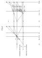
- FIG. 3 is a visible knowable lever diagram showing speed ratio relation embodying the shift stage of the 1st forward speed to the forward 10-speed and the shift stage of the 1st reverse speed in which the first clutch C1 to the fourth clutch C4, the first brake B1 and the second brake B2 at the gear train according to the present invention are operated in accordance with the operation table of FIG. 2 .
- a horizontal line where the first brake B 1 and the second brake B2 are positioned represents a rotational speed "0" and an upper horizontal line thereof represents a rotational speed "1.0" having the same rotational speed of the input shaft IN.
- a vertical line may be set with operation elements of the first, second, third and fourth planetary gear sets 10, 20, 30, 40 from the left sequentially, the intervals thereof are determined according to each gear ratio (the number of teeth of the sun gear/the number of teeth of the ring gear) of the operation elements which are directly connected with each other among the operation elements, and the position setting of each operation element has been well known to those skilled in the power train and thus omitted.
- the first clutch C1, the second clutch C2 and the second brake B2 are operated so that the 1st forward speed is embodied. Then, the operating of the first clutch C1 connects the input shaft IN at the second carrier CR2 to the third ring gear R3, the operating of the second clutch C2 connects the third carrier CR3 with the third ring gear R3 and the operating of the second brake B2 allows the fourth ring gear R4 to fix.
- the input of the input shaft IN is transmitted to the first carrier CR1 of the first planetary set 10 and the second carrier CR2 of the second planetary gear set 20, the output of the 1st forward speed is made at the fourth carrier CR4 of the fourth planetary gear set 40 as much as V1 of the horizontal line by forming a speed line of a lever line diagram by complementary operating rotation elements.
- the 1-speed output of the fourth carrier CR4 is transmitted to the differential device through the output shaft OUT, thereby the shifting of the 1 st forward speed is completed.
- the second clutch C2 the first and second brakes B1 and B2 are operated in order to form the shifting by releasing of the first clutch C1 and operating of the first brake B1 in the state of the 1 st forward speed. Then, the releasing of the first clutch C1 disconnects the third ring gear R3 from the input shaft IN, the operating of the second clutch C2 connects the third carrier CR3 to the third ring gear R3, and the operating of the first brake B1 fixes the first sun gear S 1. Due to this, the output of the 2nd forward speed is made at the fourth carrier CR4 of the fourth planetary gear set 40 as much as V2 of the horizontal line by forming a speed line of the lever line diagram by complementary operating rotation elements. The 2-speed output of the fourth carrier CR4 is transmitted to the differential device through the output shaft OUT, thereby the shifting of the 2nd forward speed is completed.
- the first clutch C1 and the first and second brakes B1 and B2 are operated to form the shifting by releasing of the second clutch C2 and operating of the first clutch C1 in the state of the 2nd forward speed. Then, the releasing of the second clutch C2 disconnects the third carrier CR3, the operating of the first clutch C1 connects the input shaft IN at the second carrier CR2 with the third ring gear R3. Due to this, the output of the forward 3-speed is made at the fourth carrier CR4 of the fourth planetary gear set 40 as much as V3 of the horizontal line by forming a speed line of the lever line diagram by complementary operating rotation elements. The 3-speed output of the fourth carrier CR4 is transmitted to the differential device through the output shaft OUT, thereby the shifting of the 3rd forward speed is completed.
- the B2 are operated to form the shifting by releasing of the first clutch C 1 and operating of the fourth clutch C4 in the state of the 3rd forward speed. Then, the releasing of the first clutch C1 disconnects the input shaft IN and the third ring gear R3, the operating of the fourth clutch C4 connects the second ring gear R2 with the output shaft OUT. Due to this, the output of the 4th forward speed is made at the fourth carrier CR4 of the fourth planetary gear set 40 as much as V4 of the horizontal line by forming a speed line of the lever line diagram by complementary operating rotation elements. The 4-speed output of the fourth carrier CR4 is transmitted to the differential device through the output shaft OUT, thereby the shifting of the 4th forward speed is completed.
- the first and fourth clutches C1 and C4 and the first brake B1 are operated to form the shifting by releasing of the second brake B2 and operating of the first clutch C1 in the state of the 4th forward speed. Then, the operating of the first clutch C1 connects the input shaft IN at the second carrier CR2 to the third ring gear R3, the releasing of the second brake B2 releases the fourth ring gear R4. Due to this, the output of the 5th forward speed is made at the fourth carrier CR4 of the fourth planetary gear set 40 as much as V5 of the horizontal line by forming a speed line of the lever line diagram by complementary operating rotation elements. The 5-speed output of the fourth carrier CR4 is transmitted to the differential device through the output shaft OUT, thereby the shifting of the 5th forward speed is completed.
- the second and fourth clutches C2 and C4 and the first brake B1 are operated to form the shifting by releasing of the first clutch C 1 and operating of the second clutch C2 in the state of the 5th forward speed. Then, the releasing of the first clutch C1 disconnects the third ring gear R3 and the input shaft IN, the operating of the second clutch C2 connects the third carrier CR3 with the third ring gear R3. Due to this, the output of the 6th forward speed is made at the fourth carrier CR4 of the fourth planetary gear set 40 as much as V6 of the horizontal line by forming a speed line of the lever line diagram by complementary operating rotation elements. The 6-speed output of the fourth carrier CR4 is transmitted to the differential device through the output shaft OUT, thereby the shifting of the 6th forward speed is completed.
- the second, third and fourth clutches C2, C3 and C4 are operated to form the shifting by releasing of the first brake B1 and operating of the third clutch C3 in the state of the 6th forward speed. Then, the releasing of the brake B 1 releases the first sun gear S1, the operating of the third clutch C3 connects the first ring gear R1 with the fourth ring gear R4. Due to this, the output of the 7th forward speed is made at the fourth carrier CR4 of the fourth planetary gear set 40 as much as V7 of the horizontal line by forming a speed line of the lever line diagram by complementary operating rotation elements. The 7-speed output of the fourth carrier CR4 is transmitted to the differential device through the output shaft OUT, thereby the shifting of the 7th forward speed is completed.
- the third and fourth clutches C3 and C4 and the first brake B1 are operated to form the shifting by releasing of the second clutch C2 and operating of the first brake B1 in the state of the 7th forward speed. Then, the releasing of the second clutch C2 disconnects the third carrier CR3, the operating of the first brake B1 fixes the first sun gear S1. Due to this, the output of the 8th forward speed is made at the fourth carrier CR4 of the fourth planetary gear set 40 as much as V8 of the horizontal line by forming a speed line of the lever line diagram by complementary operating rotation elements. The 8-speed output of the fourth carrier CR4 is transmitted to the differential device through the output shaft OUT, thereby the shifting of the 8th forward speed is completed.
- the second and third clutches C2 and C3 and the first brake B1 are operated to form the shifting by releasing of the fourth clutch C4 and operating of the second clutch C2 in the state of the 8th forward speed. Then, the releasing of the fourth clutch C4 disconnects the output shaft OUT with the second ring gear R2, the operating of the second clutch C2 connects the third carrier CR3 with the third ring gear R3. Due to this, the output of the forward 9-speed is made at the fourth carrier CR4 of the fourth planetary gear set 40 as much as V9 of the horizontal line by forming a speed line of the lever line diagram by complementary operating rotation elements. The 9-speed output of the fourth carrier CR4 is transmitted to the differential device through the output shaft OUT, thereby the shifting of the 9th forward speed is completed.
- the first and third clutches C 1 and C3 and the first brake B1 are operated to form the shifting by releasing of the second clutch C2 and operating of the first clutch C1 in the state of the 9th forward speed. Then, the releasing of the second clutch C2 disconnects the third carrier CR3, the operating of the first clutch C1 connects the input shaft IN at the second carrier CR2 with the third ring gear R3. Due to this, the output of the 10th forward speed is made at the fourth carrier CR4 of the fourth planetary gear set 40 as much as V10 of the horizontal line by forming a speed line of the lever line diagram by complementary operating rotation elements. The 10-speed output of the fourth carrier CR4 is transmitted to the differential device through the output shaft OUT, thereby the shifting of the 10th forward speed is completed.
- the first and third clutches C1 and C3 and the second brake B2 are operated to form the shifting. Then, the operating of the first clutch C1 connects the input shaft IN at the second carrier CR2 with the third ring gear R3, the operating of the third clutch C3 connects the first ring gear R1 with the fourth ring gear R4, and the operating of the second brake B2 allows the fourth ring gear R4 to fix.
- the input of the input shaft IN is transmitted to the first carrier CR1 of the first planetary gear set 10 and the fourth ring gear R4 of the fourth planetary gear set 40, and the output of the 1 reverse speed is made at the fourth carrier CR4 of the fourth planetary gear set 40 as much as R1 of the horizontal line by forming a speed line of the lever line diagram by complementary operating rotation elements, the reverse 1-speed output of the fourth carrier CR4 is transmitted to the differential device through the output shaft OUT, thereby the shifting of the 1st reverse speed is completed.
- the multi-stages automatic transmission for the vehicle includes a gear train including four planetary gear sets 10, 20, 30 and 40, six friction members made of the first, second, third and fourth clutches C1, C2, C3 and C4 and the first and second brakes B1 and B2, thereby the forward 10-speed and reverse 1-speed with a various array of the first, second, third and fourth clutches C1, C2, C3 and C4 on rotation elements may be embodied variously.
Landscapes
- Engineering & Computer Science (AREA)
- General Engineering & Computer Science (AREA)
- Mechanical Engineering (AREA)
- Structure Of Transmissions (AREA)
Abstract
Description
- The present application claims priority to Korean Patent Application No.
10-2014-0139590, filed October 16, 2014 - The present invention relates to a multi-stages automatic transmission for a vehicle, and more particularly, to a multi-stages automatic transmission for a vehicle equipped with a gear train embodying 10 forward speeds and 1 reverse speed with gear efficiency 98.6%.
- Recently, the technology development need for performance improvement has emerged similarly in the power train field by requirement of a higher need for fuel efficiency improvements due to strengthening of environmental regulations or rising oil prices.
- Appropriate power train technologies corresponding to the need have been provided, including an engine downsizing technology and a multi-staging technology of an automatic transmission. The engine downsizing has merits of reducing weight and improving fuel efficiency, and particularly, the automatic transmission multi-staging has merits of securing drivability and competitiveness of fuel efficiency at the same time through design of an excellent gear ratio in terms of power performance and fuel efficiency by using more shift stages as compared to a 4-speed (or 5-speed), and 1 reverse speed automatic transmission.
- An instance of such multi-staging of the automatic transmission, includes an 8 forward speed and 1 reverse speed automatic transmission by combining three planetary gear sets and six friction elements, and 9 forward speed and 1 reverse speed automatic transmission by combining four planetary gear sets, four friction elements and two dog clutches.
- The information disclosed in this Background of the Invention section is only for enhancement of understanding of the general background of the invention and should not be taken as an acknowledgement or any form of suggestion that this information forms the prior art already known to a person skilled in the art.
- In the related art, a problem arises in that in an automatic transmission, when the number of shift stages is increased, the number of internal components that make up the automatic transmission is increased when implementing the shift stages with a gear train through a planetary gear set. Thus, in the multi-staging of the automatic transmission, above all it is important to achieve drivability and fuel efficiency competitiveness with the gear train structure without increasing the number of internal components, thus worsening vehicle mount ability, decreasing power transmission efficiency, and increasing weight and manufacturing cost.
- Therefore, an optimal structure of the gear train which may lead to maximum efficiency with fewer components should be applied to the development of the 10 forward speed and 1 reverse speed automatic transmission to enhance the fuel efficiency effect with the increased shift stages compared to eight forward stages and one reverse stage of the automatic transmission or nine forward speed and 1 reverse speed automatic transmission.
- Various aspects of the present invention are directed to providing a multi-stages automatic transmission for a vehicle that improves drivability of the vehicle using an operation point of a low RPM range of an engine by implementing 10 forward speeds and 1 reverse speed with the gear train using four planetary gear sets, four clutches and two brakes, and especially, achieves better fuel efficiency improvement with the gear train implementing gear efficiency of 98.6%.
- According to various aspects of the present invention, a multi-stages automatic transmission for a vehicle may include first, second, third and fourth planetary gear sets each including first, second and third rotation elements, respectively, and friction members including first, second, third and fourth clutches and first and second brakes, in which an input shaft may be fixedly connected to the second rotation element of the first planetary gear set and the second rotation element of the second planetary gear set, the third rotation element of the first planetary gear set may be fixedly connected to the second rotation element of the third planetary gear set, the first rotation element of the second planetary gear set may be fixedly connected to the first rotation element of the fourth planetary gear set, the first rotation element of the third planetary gear set may be fixedly connected to the first rotation element of the fourth planetary gear set, and an output shaft may be fixedly connected to the second rotation element of the fourth planetary gear set.
- The first break may fix the first rotation element of the first planetary gear set, the second break may fix the third rotation element of the fourth planetary gear set, the first clutch may connect the second rotation element of the second planetary gear set with the third rotation element of the third planetary gear set, the second clutch may connect the first rotation element of the third planetary gear set with the third rotation element of the third planetary gear set, the third clutch may connect the third rotation element of the first planetary gear set with the third rotation element of the fourth planetary gear set, and the fourth clutch may connect the third rotation element of the second planetary gear set with the output shaft.
- The first planetary gear set and the second planetary gear set may comprise a first complex planetary gear set, and the third planetary gear set and the fourth planetary gear set comprise a second complex planetary gear set.
- The first planetary gear set may include a first sun gear as the first rotation element, a first carrier as the second rotation element, and a first ring gear as the third rotation element, the second planetary gear set may include a second sun gear as the first rotation element, a second carrier as the second rotation element, and a second ring gear as the third rotation element, the third planetary gear set may include a third sun gear as the first rotation element, a third carrier as the second rotation element, and a third ring gear as the third rotation element, and the fourth planetary gear set may include a fourth sun gear as the first rotation element, a fourth carrier as the second rotation element, and a fourth ring gear as the third rotation element.
- The first sun gear among the first sun gear, the first carrier and the first ring gear of the first planetary gear set may be fixed with the first brake, the first carrier may be continuously fixed with the input shaft to connect with the second carrier, and the first ring gear may be fixedly connected to the third carrier and selectively connected to the second brake through the third clutch.
- The second sun gear among the second sun gear, the second carrier and the second ring gear of the second planetary gear set may be continuously fixed with the fourth sun gear, the second carrier may be continuously fixed to the input shaft and selectively connected with the third ring gear through the first clutch, and the second ring gear may be selectively connected with the output shaft through the fourth clutch.
- The third sun gear among the third sun gear, the third carrier, and the third ring gear of the third planetary gear set may be continuously fixed with the fourth sun gear, the third carrier may be selectively connected with the fourth ring gear through the third clutch, and the third ring gear may be selectively connected with the third carrier through the second clutch.
- The fourth sun gear among the fourth sun gear, the fourth carrier, and the fourth ring gear of the fourth planetary gear set may be continuously fixed with the third sun gear, the fourth carrier may be fixedly connected with the output shaft, and the fourth ring gear may be fixed with the second brake and selectively connected with the first ring gear through the third clutch.
- As such, the multi-stages automatic transmission of the present invention implements 10 forward speeds and 1 reverse speed with the gear train using the four planetary gear sets, the four clutches, and the two brakes, thereby realizing an effect that the elements for a transmission implementing 10 forward speeds and 1 reverse speed are minimized.
- Also, the multi-stages automatic transmission of the present invention has an effect that simultaneously achieves the fuel efficiency improvement according to forward 10-speeds by the structure of the optimized gear train with gear efficiency of 98.6% and improves drivability of the vehicle by using an operation point of a low RPM range of the engine.
- In addition, the present invention has an effect of responding quickly to a market for the multi-stages automatic transmissions having an increased mounting ratio of more than 7-speed automatic transmission.
- It is understood that the term "vehicle" or "vehicular" or other similar terms as used herein is inclusive of motor vehicles in general such as passenger automobiles including sports utility vehicles (SUV), buses, trucks, various commercial vehicles, watercraft including a variety of boats and ships, aircraft, and the like, and includes hybrid vehicles, electric vehicles, plug-in hybrid electric vehicles, hydrogen-powered vehicles and other alternative fuel vehicles (e.g., fuel derived from resources other than petroleum). As referred to herein, a hybrid vehicle is a vehicle that has two or more sources of power, for example, both gasoline-powered and electric-powered vehicles.
- The methods and apparatuses of the present invention have other features and advantages which will be apparent from or are set forth in more detail in the accompanying drawings, which are incorporated herein, and the following Detailed Description, which together serve to explain certain principles of the present invention.
-
-
FIG. 1 is a gear train configuration of an exemplary multi-stages automatic transmission for a vehicle according to the present invention. -
FIG. 2 is an operational view at each shift stage of friction members applied to a gear train of the exemplary multi-stages automatic transmission according to the present invention. -
FIG. 3 is a lever diagram of a gear train according to the present invention. - It should be understood that the appended drawings are not necessarily to scale, presenting a somewhat simplified representation of various features illustrative of the basic principles of the invention. The specific design features of the present invention as disclosed herein, including, for example, specific dimensions, orientations, locations, and shapes will be determined in part by the particular intended application and use environment.
- Reference will now be made in detail to various embodiments of the present invention(s), examples of which are illustrated in the accompanying drawings and described below. While the invention(s) will be described in conjunction with exemplary embodiments, it will be understood that the present description is not intended to limit the invention(s) to those exemplary embodiments. On the contrary, the invention(s) is/are intended to cover not only the exemplary embodiments, but also various alternatives, modifications, equivalents and other embodiments, which may be included within the spirit and scope of the invention as defined by the appended claims.
-
FIG. 1 shows a configuration of a gear train of a multi-stages automatic transmission for a vehicle according to the present invention. As shown, an input at a gear train is achieved through an input shaft IN as an input member and an output gets out to an output shaft OUT as an output member. The input shaft IN means a turbine shaft of a torque convert into which the rotational power from an engine crank shaft is torque-converted and then inputted. The output shaft OUT is connected to a well-known differential device rotating driving wheels. - To achieve this, the gear train may include four
planetary gear sets clutch set 50 including a first, second, third and fourth clutches C1, C2, C3, C4, abrake set 60 including first and second brakes B1, B2, thereby embodying a forward 10-speed and a reverse 1-speed through the selective operations of four planetary gear sets and six friction members. Particularly, the four planetary gear sets 10, 20, 30, 40 may be classified into a first complex planetary gear device including the firstplanetary gear set 10 and the second planetary gear set 20 and a second complex planetary device including the third planetary gear set 30 and the fourth planetary gear set 40. The first complex planetary gear device and the second complex planetary gear device may be connected each other through at least one continuous combination route and through at least two selective combination route. - In the concrete, a first rotation element of the first
planetary gear set 10 may be fixed with a first brake B1, a second rotation element of the firstplanetary gear set 10 may be continuously fixed with the input shaft IN to fixedly connect to a second rotation element of the secondplanetary gear set 20, a third rotation element of the firstplanetary gear set 10 may be fixedly connected to a second rotation element of the thirdplanetary gear set 30 and may be selectively connected to the second brake B2 through the third clutch C3. A first rotation element of the secondplanetary gear set 20 may be continuously fixed with a first rotation element of the fourthplanetary gear set 40, a second rotation element of the secondplanetary gear set 20 may be continuously fixed to the input shaft IN to selectively connect to a third rotation element of the third planetary gear set 30 through the first clutch C1, and a third rotation element of the secondplanetary gear set 20 may be selectively connected to the output shaft OUT through the fourth clutch C4. A first rotation element of the thirdplanetary gear set 30 may be continuously fixed with a first rotation element of the fourthplanetary gear set 40, a second rotation element of the thirdplanetary gear set 30 may be selectively connected to a third rotation element of the fourth planetary gear set 40 through the third clutch C3, and a third rotation element of the thirdplanetary gear set 30 may be selectively connected to a third rotation element of the fourth planetary gear set 40 through the second and third clutches C2, C3. A first rotation element of the fourthplanetary gear set 40 may be continuously fixed with a first rotation element of the thirdplanetary gear set 30, a second rotation element of the fourthplanetary gear set 40 may be fixedly connected to the output shaft OUT, and a third rotation element of the fourthplanetary gear set 40 may be fixed with the second brake B2 and selectively connected to a third rotation element of the first planetary gear set 10 through the third clutch C3. - Therefore, the first, second, third and fourth
planetary gear sets planetary gear set 10 are a first sun gear S1 as the first rotation element, a first carrier CR1 as the second rotation element and a first ring gear R1 as the third rotation element, respectively. The first, second and third rotation elements of the secondplanetary gear set 20 are a second sun gear S2 as the first rotation element, a second carrier CR2 as the second rotation element and a second ring gear R2 as the third rotation element, respectively. The first, second and third rotation elements of the thirdplanetary gear set 30 are a third sun gear S3 as the first rotation element, a third carrier CR3 as the second rotation element and a third ring gear R3 as the third rotation element, respectively. The first, second and third rotation elements of the fourthplanetary gear set 40 are a fourth sun gear S4 as the first rotation element, a fourth carrier CR4 as the second rotation element and a fourth ring gear R4 as the third rotation element, respectively. - Specifically, the first sun gear S1 may be fixed with the first brake B1. The first carrier CR1 may be continuously fixed with the input shaft IN to fixedly connect to the second carrier CR2. The first ring gear R1 may be fixedly connected to the third carrier CR3 and may be selectively fixed with the second brake B2 through the third clutch C3. Thus, the continuous combination route between the first complex planetary gear set including the first and second
planetary gear sets planetary gear sets - Concretely, the second sun gear S2 may be continuously connected to the fourth sun gear S4. The second carrier CR2 may be continuously fixed with the input shaft IN and selectively connected to the third ring gear R3 through the first clutch C1. The second ring gear R2 may be selectively connected to the output shaft OUT through the fourth clutch C4. Thus, the second ring gear R2 along with the fourth carrier CR4 acts selectively as a gear train output element.
- Specifically, the third sun gear S3 may be continuously fixed with the fourth sun gear S4. The third carrier CR3 may be selectively connected with the fourth ring gear R4 through the third clutch C3. The third ring gear R3 may be selectively connected with the third carrier CR3 through the second clutch C2.
- Concretely, the fourth sun gear S4 may be continuously connected to the third sun gear S3. The fourth carrier CR4 may be fixedly connected with the output shaft OUT. The fourth ring gear R4 may be fixed with the second brake B2 and selectively connected to the first ring gear R1 through the third clutch C3. Thus, the fourth carrier CR4 acts as a gear train output element.
- Moreover, the first, second, third and fourth clutches C1, C2, C3, C4 and the first and second brakes B1, B2 consisting of six friction members may be made up of a hydraulic multi-plates friction combination unit friction-coupled by hydraulic pressure, ordinary ways.
- Specifically, the first brake B1 is disposed in front of the first planetary gear set 10, the second brake B2 is disposed in the rear of the fourth planetary gear set 40, the first clutch C1 is disposed between the rear of the second planetary gear set 20 and the front of the third planetary gear set 30, the second and third clutches C2, C3 are disposed between the rear of the third planetary gear set 30 and the front of the fourth planetary gear set 40, and the fourth clutch C4 is disposed in the rear of the fourth planetary gear set 40. By applying such arrangement, the hydraulic pressure passage supplied to the friction members may be easily formed and the distribution of weight is uniform, thereby improving the total weight balance of the automatic transmission.
- Concretely, the first brake B1 may fix the first sun gear S1 and the second brake B2 may fix the fourth ring gear R4. The first clutch C1 may selectively connect the second carrier CR2 and the third ring gear R3, the second clutch C2 may selectively connect the third carrier CR3 and the third ring gear R3, the third clutch C3 may selectively connect the first ring rear R1 and the fourth ring gear R4, and the fourth clutch C4 may selectively connect the second ring gear R2 and the output shaft OUT.
- As such, since each shift stage may be embodied by coupling all three operation elements, the number of inoperative friction elements is reduced, thereby decreasing friction drag loss.
- On the other hand,
FIG. 2 is operational elements at each shift stage of the friction members applied to a gear train in accordance with an exemplary embodiment of the present invention.FIG. 3 is a visible knowable lever diagram showing speed ratio relation embodying the shift stage of the 1st forward speed to the forward 10-speed and the shift stage of the 1st reverse speed in which the first clutch C1 to the fourth clutch C4, the first brake B1 and the second brake B2 at the gear train according to the present invention are operated in accordance with the operation table ofFIG. 2 . At the lever analysis diagram, a horizontal line where thefirst brake B 1 and the second brake B2 are positioned represents a rotational speed "0" and an upper horizontal line thereof represents a rotational speed "1.0" having the same rotational speed of the input shaft IN. Furthermore, a vertical line may be set with operation elements of the first, second, third and fourth planetary gear sets 10, 20, 30, 40 from the left sequentially, the intervals thereof are determined according to each gear ratio (the number of teeth of the sun gear/the number of teeth of the ring gear) of the operation elements which are directly connected with each other among the operation elements, and the position setting of each operation element has been well known to those skilled in the power train and thus omitted. - At the 1st forward speed, the first clutch C1, the second clutch C2 and the second brake B2 are operated so that the 1st forward speed is embodied. Then, the operating of the first clutch C1 connects the input shaft IN at the second carrier CR2 to the third ring gear R3, the operating of the second clutch C2 connects the third carrier CR3 with the third ring gear R3 and the operating of the second brake B2 allows the fourth ring gear R4 to fix. Due to this, the input of the input shaft IN is transmitted to the first carrier CR1 of the first planetary set 10 and the second carrier CR2 of the second planetary gear set 20, the output of the 1st forward speed is made at the fourth carrier CR4 of the fourth planetary gear set 40 as much as V1 of the horizontal line by forming a speed line of a lever line diagram by complementary operating rotation elements. The 1-speed output of the fourth carrier CR4 is transmitted to the differential device through the output shaft OUT, thereby the shifting of the 1 st forward speed is completed.
- At the 2nd forward speed, the second clutch C2, the first and second brakes B1 and B2 are operated in order to form the shifting by releasing of the first clutch C1 and operating of the first brake B1 in the state of the 1 st forward speed. Then, the releasing of the first clutch C1 disconnects the third ring gear R3 from the input shaft IN, the operating of the second clutch C2 connects the third carrier CR3 to the third ring gear R3, and the operating of the first brake B1 fixes the first
sun gear S 1. Due to this, the output of the 2nd forward speed is made at the fourth carrier CR4 of the fourth planetary gear set 40 as much as V2 of the horizontal line by forming a speed line of the lever line diagram by complementary operating rotation elements. The 2-speed output of the fourth carrier CR4 is transmitted to the differential device through the output shaft OUT, thereby the shifting of the 2nd forward speed is completed. - At the 3rd forward speed, the first clutch C1 and the first and second brakes B1 and B2 are operated to form the shifting by releasing of the second clutch C2 and operating of the first clutch C1 in the state of the 2nd forward speed. Then, the releasing of the second clutch C2 disconnects the third carrier CR3, the operating of the first clutch C1 connects the input shaft IN at the second carrier CR2 with the third ring gear R3. Due to this, the output of the forward 3-speed is made at the fourth carrier CR4 of the fourth planetary gear set 40 as much as V3 of the horizontal line by forming a speed line of the lever line diagram by complementary operating rotation elements. The 3-speed output of the fourth carrier CR4 is transmitted to the differential device through the output shaft OUT, thereby the shifting of the 3rd forward speed is completed.
- At the 4th forward speed, the fourth clutch C4 and the first and second brake B1,
- B2 are operated to form the shifting by releasing of the first
clutch C 1 and operating of the fourth clutch C4 in the state of the 3rd forward speed. Then, the releasing of the first clutch C1 disconnects the input shaft IN and the third ring gear R3, the operating of the fourth clutch C4 connects the second ring gear R2 with the output shaft OUT. Due to this, the output of the 4th forward speed is made at the fourth carrier CR4 of the fourth planetary gear set 40 as much as V4 of the horizontal line by forming a speed line of the lever line diagram by complementary operating rotation elements. The 4-speed output of the fourth carrier CR4 is transmitted to the differential device through the output shaft OUT, thereby the shifting of the 4th forward speed is completed. - At the 5th forward speed, the first and fourth clutches C1 and C4 and the first brake B1 are operated to form the shifting by releasing of the second brake B2 and operating of the first clutch C1 in the state of the 4th forward speed. Then, the operating of the first clutch C1 connects the input shaft IN at the second carrier CR2 to the third ring gear R3, the releasing of the second brake B2 releases the fourth ring gear R4. Due to this, the output of the 5th forward speed is made at the fourth carrier CR4 of the fourth planetary gear set 40 as much as V5 of the horizontal line by forming a speed line of the lever line diagram by complementary operating rotation elements. The 5-speed output of the fourth carrier CR4 is transmitted to the differential device through the output shaft OUT, thereby the shifting of the 5th forward speed is completed.
- At the 6th forward speed, the second and fourth clutches C2 and C4 and the first brake B1 are operated to form the shifting by releasing of the first
clutch C 1 and operating of the second clutch C2 in the state of the 5th forward speed. Then, the releasing of the first clutch C1 disconnects the third ring gear R3 and the input shaft IN, the operating of the second clutch C2 connects the third carrier CR3 with the third ring gear R3. Due to this, the output of the 6th forward speed is made at the fourth carrier CR4 of the fourth planetary gear set 40 as much as V6 of the horizontal line by forming a speed line of the lever line diagram by complementary operating rotation elements. The 6-speed output of the fourth carrier CR4 is transmitted to the differential device through the output shaft OUT, thereby the shifting of the 6th forward speed is completed. - At the 7th forward speed, the second, third and fourth clutches C2, C3 and C4 are operated to form the shifting by releasing of the first brake B1 and operating of the third clutch C3 in the state of the 6th forward speed. Then, the releasing of the
brake B 1 releases the first sun gear S1, the operating of the third clutch C3 connects the first ring gear R1 with the fourth ring gear R4. Due to this, the output of the 7th forward speed is made at the fourth carrier CR4 of the fourth planetary gear set 40 as much as V7 of the horizontal line by forming a speed line of the lever line diagram by complementary operating rotation elements. The 7-speed output of the fourth carrier CR4 is transmitted to the differential device through the output shaft OUT, thereby the shifting of the 7th forward speed is completed. - At the 8th forward speed, the third and fourth clutches C3 and C4 and the first brake B1 are operated to form the shifting by releasing of the second clutch C2 and operating of the first brake B1 in the state of the 7th forward speed. Then, the releasing of the second clutch C2 disconnects the third carrier CR3, the operating of the first brake B1 fixes the first sun gear S1. Due to this, the output of the 8th forward speed is made at the fourth carrier CR4 of the fourth planetary gear set 40 as much as V8 of the horizontal line by forming a speed line of the lever line diagram by complementary operating rotation elements. The 8-speed output of the fourth carrier CR4 is transmitted to the differential device through the output shaft OUT, thereby the shifting of the 8th forward speed is completed.
- At the 9th forward speed, the second and third clutches C2 and C3 and the first brake B1 are operated to form the shifting by releasing of the fourth clutch C4 and operating of the second clutch C2 in the state of the 8th forward speed. Then, the releasing of the fourth clutch C4 disconnects the output shaft OUT with the second ring gear R2, the operating of the second clutch C2 connects the third carrier CR3 with the third ring gear R3. Due to this, the output of the forward 9-speed is made at the fourth carrier CR4 of the fourth planetary gear set 40 as much as V9 of the horizontal line by forming a speed line of the lever line diagram by complementary operating rotation elements. The 9-speed output of the fourth carrier CR4 is transmitted to the differential device through the output shaft OUT, thereby the shifting of the 9th forward speed is completed.
- At the 10th forward speed, the first and
third clutches C 1 and C3 and the first brake B1 are operated to form the shifting by releasing of the second clutch C2 and operating of the first clutch C1 in the state of the 9th forward speed. Then, the releasing of the second clutch C2 disconnects the third carrier CR3, the operating of the first clutch C1 connects the input shaft IN at the second carrier CR2 with the third ring gear R3. Due to this, the output of the 10th forward speed is made at the fourth carrier CR4 of the fourth planetary gear set 40 as much as V10 of the horizontal line by forming a speed line of the lever line diagram by complementary operating rotation elements. The 10-speed output of the fourth carrier CR4 is transmitted to the differential device through the output shaft OUT, thereby the shifting of the 10th forward speed is completed. - At the 1 reverse speed, the first and third clutches C1 and C3 and the second brake B2 are operated to form the shifting. Then, the operating of the first clutch C1 connects the input shaft IN at the second carrier CR2 with the third ring gear R3, the operating of the third clutch C3 connects the first ring gear R1 with the fourth ring gear R4, and the operating of the second brake B2 allows the fourth ring gear R4 to fix. Due to this, the input of the input shaft IN is transmitted to the first carrier CR1 of the first planetary gear set 10 and the fourth ring gear R4 of the fourth planetary gear set 40, and the output of the 1 reverse speed is made at the fourth carrier CR4 of the fourth planetary gear set 40 as much as R1 of the horizontal line by forming a speed line of the lever line diagram by complementary operating rotation elements, the reverse 1-speed output of the fourth carrier CR4 is transmitted to the differential device through the output shaft OUT, thereby the shifting of the 1st reverse speed is completed.
- As described above, the multi-stages automatic transmission for the vehicle according to various embodiments of the present invention includes a gear train including four planetary gear sets 10, 20, 30 and 40, six friction members made of the first, second, third and fourth clutches C1, C2, C3 and C4 and the first and second brakes B1 and B2, thereby the forward 10-speed and reverse 1-speed with a various array of the first, second, third and fourth clutches C1, C2, C3 and C4 on rotation elements may be embodied variously.
- The foregoing descriptions of specific exemplary embodiments of the present invention have been presented for purposes of illustration and description. They are not intended to be exhaustive or to limit the invention to the precise forms disclosed, and obviously many modifications and variations are possible in light of the above teachings. The exemplary embodiments were chosen and described in order to explain certain principles of the invention and their practical application, to thereby enable others skilled in the art to make and utilize various exemplary embodiments of the present invention, as well as various alternatives and modifications thereof. It is intended that the scope of the invention be defined by the Claims appended hereto and their equivalents.
Claims (10)
- A multi-stages automatic transmission for a vehicle comprising:first, second, third and fourth planetary gear sets, each including first, second and third rotation elements, respectively; andfriction members including first, second, third and fourth clutches and first and second brakes,wherein an input shaft is fixedly connected to the second rotation element of the first planetary gear set and the second rotation element of the second planetary gear set, the third rotation element of the first planetary gear set is fixedly connected to the second rotation element of the third planetary gear set, the first rotation element of the second planetary gear set is fixedly connected to the first rotation element of the fourth planetary gear set, the first rotation element of the third planetary gear set is fixedly connected to the first rotation element of the fourth planetary gear set, and an output shaft is fixedly connected to the second rotation element of the fourth planetary gear set.
- The multi-stages automatic transmission for the vehicle of claim 1, wherein the first break selectively fixes the first rotation element of the first planetary gear set, the second break selectively fixes the third rotation element of the fourth planetary gear set, the first clutch selectively connects the second rotation element of the second planetary gear set with the third rotation element of the third planetary gear set, the second clutch selectively connects the first rotation element of the third planetary gear set with the third rotation element of the third planetary gear set, the third clutch selectively connects the third rotation element of the first planetary gear set with the third rotation element of the fourth planetary gear set, and the fourth clutch selectively connects the third rotation element of the second planetary gear set with the output shaft.
- The multi-stages automatic transmission for the vehicle of claim 1, wherein the first planetary gear set and the second planetary gear set comprise a first complex planetary gear set, and the third planetary gear set and the fourth planetary gear set comprise a second complex planetary gear set.
- The multi-stages automatic transmission for the vehicle of claim 1, wherein the first planetary gear set comprises a first sun gear as the first rotation element, a first carrier as the second rotation element, and a first ring gear as the third rotation element,
the second planetary gear set comprises a second sun gear as the first rotation element, a second carrier as the second rotation element, and a second ring gear as the third rotation element,
the third planetary gear set comprises a third sun gear as the first rotation element, a third carrier as the second rotation element, and a third ring gear as the third rotation element, and
the fourth planetary gear set comprises a fourth sun gear as the first rotation element, a fourth carrier as the second rotation element, and a fourth ring gear as the third rotation element. - The multi-stages automatic transmission for the vehicle of claim 2, wherein the first planetary gear set comprises a first sun gear as the first rotation element, a first carrier as the second rotation element, and a first ring gear as the third rotation element,
the second planetary gear set comprises a second sun gear as the first rotation element, a second carrier as the second rotation element, and a second ring gear as the third rotation element,
the third planetary gear set comprises a third sun gear as the first rotation element, a third carrier as the second rotation element, and a third ring gear as the third rotation element, and
the fourth planetary gear set comprises a fourth sun gear as the first rotation element, a fourth carrier as the second rotation element, and a fourth ring gear as the third rotation element. - The multi-stages automatic transmission for the vehicle of claim 3, wherein the first planetary gear set comprises a first sun gear as the first rotation element, a first carrier as the second rotation element, and a first ring gear as the third rotation element,
the second planetary gear set comprises a second sun gear as the first rotation element, a second carrier as the second rotation element, and a second ring gear as the third rotation element,
the third planetary gear set comprises a third sun gear as the first rotation element, a third carrier as the second rotation element, and a third ring gear as the third rotation element, and
the fourth planetary gear set comprises a fourth sun gear as the first rotation element, a fourth carrier as the second rotation element, and a fourth ring gear as the third rotation element. - The multi-stages automatic transmission for the vehicle according to any one of the claims 4, 5 or 6, wherein the first sun gear among the first sun gear, the first carrier and the first ring gear of the first planetary gear set is fixed with the first brake, the first carrier is continuously fixed with the input shaft to connect with the second carrier, and the first ring gear is fixedly connected to the third carrier and selectively connected to the second brake through the third clutch.
- The multi-stages automatic transmission for the vehicle according to any one of the of claims 4, 5 or 6, wherein the second sun gear among the second sun gear, the second carrier and the second ring gear of the second planetary gear set is continuously fixed with the fourth sun gear, the second carrier is continuously fixed to the input shaft and selectively connected with the third ring gear through the first clutch, and the second ring gear is selectively connected with the output shaft through the fourth clutch.
- The multi-stages automatic transmission for the vehicle according to any one of the claims 4, 5 or 6, wherein the third sun gear among the third sun gear, the third carrier, and the third ring gear of the third planetary gear set is continuously fixed with the fourth sun gear, the third carrier is selectively connected with the fourth ring gear through the third clutch, and the third ring gear is selectively connected with the third carrier through the second clutch.
- The multi-stages automatic transmission for the vehicle according to any one of the claims 4, 5 or 6, wherein the fourth sun gear among the fourth sun gear, the fourth carrier, and the fourth ring gear of the fourth planetary gear set is continuously fixed with the third sun gear, the fourth carrier is fixedly connected with the output shaft, and the fourth ring gear is fixed with the second brake and selectively connected with the first ring gear through the third clutch.
Applications Claiming Priority (1)
| Application Number | Priority Date | Filing Date | Title |
|---|---|---|---|
| KR1020140139590A KR101646352B1 (en) | 2014-10-16 | 2014-10-16 | Multi Stage Auto Transmission for Vehicle |
Publications (2)
| Publication Number | Publication Date |
|---|---|
| EP3009712A1 true EP3009712A1 (en) | 2016-04-20 |
| EP3009712B1 EP3009712B1 (en) | 2019-07-10 |
Family
ID=53268638
Family Applications (1)
| Application Number | Title | Priority Date | Filing Date |
|---|---|---|---|
| EP15168095.6A Active EP3009712B1 (en) | 2014-10-16 | 2015-05-19 | Multi-stages automatic transmission for vehicle |
Country Status (5)
| Country | Link |
|---|---|
| US (1) | US9453559B2 (en) |
| EP (1) | EP3009712B1 (en) |
| JP (1) | JP6541395B2 (en) |
| KR (1) | KR101646352B1 (en) |
| CN (1) | CN106195157B (en) |
Cited By (3)
| Publication number | Priority date | Publication date | Assignee | Title |
|---|---|---|---|---|
| CN107542862A (en) * | 2016-06-27 | 2018-01-05 | 现代自动车株式会社 | Epicyclic train for the automatic transmission of vehicle |
| CN107816523A (en) * | 2016-09-12 | 2018-03-20 | 现代自动车株式会社 | Epicyclic train for the automatic transmission of vehicle |
| DE102015108990B4 (en) | 2014-11-04 | 2022-03-31 | Hyundai Motor Company | Gear train of a multi-stage automatic transmission for a vehicle |
Families Citing this family (8)
| Publication number | Priority date | Publication date | Assignee | Title |
|---|---|---|---|---|
| KR101646353B1 (en) | 2014-10-16 | 2016-08-08 | 현대자동차주식회사 | Multi Stage Auto Transmission for Vehicle |
| KR101646352B1 (en) | 2014-10-16 | 2016-08-08 | 현대자동차주식회사 | Multi Stage Auto Transmission for Vehicle |
| KR101693933B1 (en) * | 2014-11-04 | 2017-01-06 | 현대자동차주식회사 | Multi Stage Auto Transmission for Vehicle |
| KR101765605B1 (en) * | 2015-09-14 | 2017-08-07 | 현대자동차 주식회사 | Planetary gear train of automatic transmission for vehicles |
| KR101896330B1 (en) * | 2016-09-12 | 2018-09-07 | 현대자동차 주식회사 | Planetary gear train of automatic transmission for vehicles |
| KR101896329B1 (en) * | 2016-09-12 | 2018-09-07 | 현대자동차 주식회사 | Planetary gear train of automatic transmission for vehicles |
| KR101916065B1 (en) * | 2016-10-25 | 2018-11-07 | 현대자동차 주식회사 | Planetary gear train of automatic transmission for vehicles |
| CN112096852B (en) * | 2020-09-27 | 2021-05-25 | 吉林大学 | A Design Method for Shifting Regularity of Ultra-multi-speed Automatic Transmission |
Citations (3)
| Publication number | Priority date | Publication date | Assignee | Title |
|---|---|---|---|---|
| US20050003924A1 (en) * | 2003-05-27 | 2005-01-06 | Toyota Jidosha Kabushiki Kaisha | Multistage transmission |
| DE102009019046A1 (en) * | 2009-04-28 | 2010-11-04 | Daimler Ag | Automatic transmission device for drive train of motor vehicle, has drift unit and planet pinion carrier connected with each other in torque proof manner, and three coupling elements connected with each other in torque proof manner |
| WO2013100620A1 (en) * | 2011-12-29 | 2013-07-04 | 현대 파워텍 주식회사 | 10-shift power train of automatic transmission for vehicle |
Family Cites Families (46)
| Publication number | Priority date | Publication date | Assignee | Title |
|---|---|---|---|---|
| CN100540943C (en) * | 2004-12-28 | 2009-09-16 | 丰田自动车株式会社 | Multi-speed transmission for vehicles |
| DE102005002337A1 (en) * | 2005-01-17 | 2006-08-10 | Zf Friedrichshafen Ag | Multi-speed transmission |
| DE102006006639A1 (en) | 2006-02-14 | 2007-08-30 | Zf Friedrichshafen Ag | Automatic transmission for a motor vehicle comprises a drive shaft and a driven shaft arranged in a housing with planetary sets and switching elements |
| DE102006006641A1 (en) | 2006-02-14 | 2007-08-30 | Zf Friedrichshafen Ag | Multi-step gear for planetary gear e.g. automatic gearbox for motor vehicle, has four planetary trains, seven rotational shafts and six shift elements, comprising brakes and clutches |
| KR100802954B1 (en) | 2006-10-26 | 2008-02-14 | 현대자동차주식회사 | Gear train of car automatic transmission |
| US7871352B2 (en) * | 2007-04-02 | 2011-01-18 | GM Global Technology Operations LLC | Eight speed automatic transmission |
| US7651431B2 (en) | 2007-07-09 | 2010-01-26 | Gm Global Technology Operations, Inc. | 10-speed transmission |
| US7993237B2 (en) * | 2007-11-09 | 2011-08-09 | GM Global Technology Operations LLC | Transmission having ten or more speeds |
| DE102007055808A1 (en) | 2007-12-14 | 2009-06-18 | Zf Friedrichshafen Ag | 10-speed automatic transmission |
| US7946949B2 (en) * | 2008-04-21 | 2011-05-24 | GM Global Technology Operations LLC | Eight speed automatic transmission |
| DE102008055626A1 (en) * | 2008-11-03 | 2010-05-06 | Daimler Ag | gear unit |
| US8038566B2 (en) * | 2009-02-13 | 2011-10-18 | GM Global Technology Operations LLC | Multi-speed transmission |
| DE102009028713A1 (en) | 2009-08-20 | 2011-02-24 | Zf Friedrichshafen Ag | Multi-speed transmission |
| DE102009028715B4 (en) * | 2009-08-20 | 2022-02-17 | Zf Friedrichshafen Ag | multi-speed gearbox |
| KR101063505B1 (en) * | 2010-03-31 | 2011-09-07 | 현대자동차주식회사 | Gear train of car automatic transmission |
| KR101090813B1 (en) * | 2010-06-30 | 2011-12-08 | 기아자동차주식회사 | Gear train of car automatic transmission |
| JP5530340B2 (en) | 2010-11-24 | 2014-06-25 | 株式会社ケーヒン | Engine control device |
| KR101209750B1 (en) | 2011-04-21 | 2012-12-07 | 현대자동차주식회사 | Planetary gear train of automatic transmission for vehicles |
| KR101807162B1 (en) | 2011-04-21 | 2017-12-11 | 주식회사 보령바이젠셀 | Tumor antigen protein or gene of polo-like kinase 1 |
| KR101220387B1 (en) * | 2011-06-22 | 2013-01-09 | 현대자동차주식회사 | Planetary gear train of automatic transmission for vehicles |
| KR101283035B1 (en) | 2011-09-21 | 2013-07-08 | 현대자동차주식회사 | Transmission for vehicle |
| JP2013072464A (en) | 2011-09-27 | 2013-04-22 | Aisin Aw Co Ltd | Automatic transmission |
| US8715131B2 (en) | 2011-11-30 | 2014-05-06 | Gm Global Technology Operations | Multi-speed transmission having a stacked planetary gear set |
| JP5789675B2 (en) | 2011-12-16 | 2015-10-07 | ジヤトコ株式会社 | Automatic transmission for vehicles |
| US8888648B2 (en) * | 2012-02-10 | 2014-11-18 | Gm Global Technology Operations, Llc | Multi-speed transmission |
| JP5780987B2 (en) * | 2012-03-14 | 2015-09-16 | ジヤトコ株式会社 | Automatic transmission for vehicles |
| JP2013199959A (en) | 2012-03-23 | 2013-10-03 | Jatco Ltd | Automatic transmission for vehicle |
| JP5733254B2 (en) | 2012-03-28 | 2015-06-10 | アイシン・エィ・ダブリュ株式会社 | Automatic transmission |
| JP5693510B2 (en) | 2012-03-28 | 2015-04-01 | ジヤトコ株式会社 | Automatic transmission for vehicles |
| JP5693509B2 (en) * | 2012-03-28 | 2015-04-01 | ジヤトコ株式会社 | Automatic transmission for vehicles |
| JP2013204706A (en) * | 2012-03-28 | 2013-10-07 | Jatco Ltd | Automatic transmission for vehicle |
| US8821336B2 (en) | 2012-05-16 | 2014-09-02 | Gm Global Technology Operations, Llc | Multi-speed transmission and backing plate |
| US9145953B2 (en) * | 2012-05-25 | 2015-09-29 | Ford Global Technologies, Llc | Multi-speed transmission |
| US8591377B1 (en) | 2012-05-29 | 2013-11-26 | Ford Global Technologies, Llc | Multi-speed automatic transmission |
| JP2014035056A (en) | 2012-08-10 | 2014-02-24 | Aisin Aw Co Ltd | Automatic transmission |
| JP2014035057A (en) | 2012-08-10 | 2014-02-24 | Aisin Aw Co Ltd | Automatic transmission |
| KR101394033B1 (en) | 2012-10-10 | 2014-05-09 | 현대자동차 주식회사 | Planetary gear train of automatic transmission for vehicles |
| US9039565B2 (en) | 2012-10-10 | 2015-05-26 | Gm Global Technology Operations, Llc | Multi-speed transmission |
| US8777798B2 (en) | 2012-10-12 | 2014-07-15 | Gm Global Technology Operations, Llc. | Ten-speed transmission |
| JP2014105850A (en) | 2012-11-30 | 2014-06-09 | Aisin Aw Co Ltd | Automatic transmission device |
| JP2014105849A (en) | 2012-11-30 | 2014-06-09 | Aisin Aw Co Ltd | Automatic transmission device |
| JP2014105848A (en) | 2012-11-30 | 2014-06-09 | Aisin Aw Co Ltd | Automatic transmission device |
| US8591376B1 (en) | 2012-12-13 | 2013-11-26 | Hyundia Motor Company | Planetary gear train of automatic transmission for vehicle |
| KR101416108B1 (en) | 2013-08-07 | 2014-07-09 | 현대 파워텍 주식회사 | Automatic transmission for car |
| US9175748B2 (en) * | 2013-10-04 | 2015-11-03 | Ford Global Technologies, Llc | Multi-speed transmission |
| KR101646352B1 (en) | 2014-10-16 | 2016-08-08 | 현대자동차주식회사 | Multi Stage Auto Transmission for Vehicle |
-
2014
- 2014-10-16 KR KR1020140139590A patent/KR101646352B1/en not_active Expired - Fee Related
-
2015
- 2015-04-03 JP JP2015076645A patent/JP6541395B2/en not_active Expired - Fee Related
- 2015-05-19 EP EP15168095.6A patent/EP3009712B1/en active Active
- 2015-05-22 US US14/720,244 patent/US9453559B2/en not_active Expired - Fee Related
- 2015-06-05 CN CN201510305436.6A patent/CN106195157B/en not_active Expired - Fee Related
Patent Citations (3)
| Publication number | Priority date | Publication date | Assignee | Title |
|---|---|---|---|---|
| US20050003924A1 (en) * | 2003-05-27 | 2005-01-06 | Toyota Jidosha Kabushiki Kaisha | Multistage transmission |
| DE102009019046A1 (en) * | 2009-04-28 | 2010-11-04 | Daimler Ag | Automatic transmission device for drive train of motor vehicle, has drift unit and planet pinion carrier connected with each other in torque proof manner, and three coupling elements connected with each other in torque proof manner |
| WO2013100620A1 (en) * | 2011-12-29 | 2013-07-04 | 현대 파워텍 주식회사 | 10-shift power train of automatic transmission for vehicle |
Non-Patent Citations (1)
| Title |
|---|
| "DAS NEUNGANG-AUTOMATIKGETRIEBE 9G-TRONIC VON MERCEDES-BENZ", 31 January 2014 (2014-01-31), XP055175590, Retrieved from the Internet <URL:http://download.springer.com/static/pdf/181/art%3A10.1007%2Fs35148-014-0012-3.pdf?auth66=1426248756_78b6cdb924a4a3cedf89e91536aaa6ee&ext=.pdf> [retrieved on 20150311] * |
Cited By (5)
| Publication number | Priority date | Publication date | Assignee | Title |
|---|---|---|---|---|
| DE102015108990B4 (en) | 2014-11-04 | 2022-03-31 | Hyundai Motor Company | Gear train of a multi-stage automatic transmission for a vehicle |
| CN107542862A (en) * | 2016-06-27 | 2018-01-05 | 现代自动车株式会社 | Epicyclic train for the automatic transmission of vehicle |
| CN107542862B (en) * | 2016-06-27 | 2021-02-05 | 现代自动车株式会社 | Planetary gear train of automatic transmission for vehicle |
| CN107816523A (en) * | 2016-09-12 | 2018-03-20 | 现代自动车株式会社 | Epicyclic train for the automatic transmission of vehicle |
| CN107816523B (en) * | 2016-09-12 | 2021-02-05 | 现代自动车株式会社 | Planetary gear train of automatic transmission for vehicle |
Also Published As
| Publication number | Publication date |
|---|---|
| KR101646352B1 (en) | 2016-08-08 |
| EP3009712B1 (en) | 2019-07-10 |
| KR20160045162A (en) | 2016-04-27 |
| US20160108995A1 (en) | 2016-04-21 |
| JP2016080163A (en) | 2016-05-16 |
| CN106195157A (en) | 2016-12-07 |
| CN106195157B (en) | 2019-04-30 |
| US9453559B2 (en) | 2016-09-27 |
| JP6541395B2 (en) | 2019-07-10 |
Similar Documents
| Publication | Publication Date | Title |
|---|---|---|
| EP3009712B1 (en) | Multi-stages automatic transmission for vehicle | |
| US9309951B1 (en) | Planetary gear train of automatic transmission for vehicles | |
| US9464694B2 (en) | Planetary gear train of automatic transmission for vehicle | |
| US9989126B2 (en) | Planetary gear train of automatic transmission for vehicle | |
| US9631704B2 (en) | Multi-stages automatic transmission for vehicle | |
| US9958035B2 (en) | Planetary gear train of automatic transmission for vehicles | |
| US9651115B2 (en) | Planetary gear train of automatic transmission for vehicles | |
| US10119596B2 (en) | Planetary gear train of automatic transmission for vehicle | |
| US20160169342A1 (en) | Planetary gear train of automatic transmission for vehicle | |
| US9810289B2 (en) | Planetary gear train of automatic transmission for vehicles | |
| US9927007B2 (en) | Multi-stages automatic transmission for vehicle | |
| US9631705B2 (en) | Multi-stages automatic transmission for vehicle | |
| US20160333973A1 (en) | Planetary gear train of automatic transmission for vehicles | |
| US9726257B2 (en) | Planetary gear train of automatic transmission for vehicles | |
| US9784342B1 (en) | Planetary gear train of automatic transmission for vehicle | |
| US9482320B2 (en) | Planetary gear train of automatic transmission for vehicles | |
| US9518637B2 (en) | Planetary gear train of automatic transmission for vehicles | |
| US9587712B2 (en) | Planetary gear train of automatic transmission for vehicles | |
| US9945452B2 (en) | Planetary gear train of automatic transmission for vehicles | |
| US9534666B2 (en) | Planetary gear train of automatic transmission for vehicles | |
| US9863508B2 (en) | Planetary gear train of automatic transmission for vehicle | |
| US9726262B1 (en) | Planetary gear train of automatic transmission for vehicle | |
| US9850988B2 (en) | Planetary gear train of automatic transmission for vehicle | |
| US20170284514A1 (en) | Planetary gear train of automatic transmission for vehicle |
Legal Events
| Date | Code | Title | Description |
|---|---|---|---|
| PUAI | Public reference made under article 153(3) epc to a published international application that has entered the european phase |
Free format text: ORIGINAL CODE: 0009012 |
|
| AK | Designated contracting states |
Kind code of ref document: A1 Designated state(s): AL AT BE BG CH CY CZ DE DK EE ES FI FR GB GR HR HU IE IS IT LI LT LU LV MC MK MT NL NO PL PT RO RS SE SI SK SM TR |
|
| AX | Request for extension of the european patent |
Extension state: BA ME |
|
| 17P | Request for examination filed |
Effective date: 20160601 |
|
| RBV | Designated contracting states (corrected) |
Designated state(s): AL AT BE BG CH CY CZ DE DK EE ES FI FR GB GR HR HU IE IS IT LI LT LU LV MC MK MT NL NO PL PT RO RS SE SI SK SM TR |
|
| GRAP | Despatch of communication of intention to grant a patent |
Free format text: ORIGINAL CODE: EPIDOSNIGR1 |
|
| RIC1 | Information provided on ipc code assigned before grant |
Ipc: F16H 3/66 20060101AFI20181115BHEP |
|
| STAA | Information on the status of an ep patent application or granted ep patent |
Free format text: STATUS: GRANT OF PATENT IS INTENDED |
|
| INTG | Intention to grant announced |
Effective date: 20181220 |
|
| GRAS | Grant fee paid |
Free format text: ORIGINAL CODE: EPIDOSNIGR3 |
|
| GRAA | (expected) grant |
Free format text: ORIGINAL CODE: 0009210 |
|
| STAA | Information on the status of an ep patent application or granted ep patent |
Free format text: STATUS: THE PATENT HAS BEEN GRANTED |
|
| AK | Designated contracting states |
Kind code of ref document: B1 Designated state(s): AL AT BE BG CH CY CZ DE DK EE ES FI FR GB GR HR HU IE IS IT LI LT LU LV MC MK MT NL NO PL PT RO RS SE SI SK SM TR |
|
| REG | Reference to a national code |
Ref country code: GB Ref legal event code: FG4D |
|
| REG | Reference to a national code |
Ref country code: CH Ref legal event code: EP Ref country code: AT Ref legal event code: REF Ref document number: 1153908 Country of ref document: AT Kind code of ref document: T Effective date: 20190715 |
|
| REG | Reference to a national code |
Ref country code: DE Ref legal event code: R096 Ref document number: 602015033405 Country of ref document: DE |
|
| REG | Reference to a national code |
Ref country code: IE Ref legal event code: FG4D |
|
| REG | Reference to a national code |
Ref country code: NL Ref legal event code: MP Effective date: 20190710 |
|
| REG | Reference to a national code |
Ref country code: LT Ref legal event code: MG4D |
|
| REG | Reference to a national code |
Ref country code: AT Ref legal event code: MK05 Ref document number: 1153908 Country of ref document: AT Kind code of ref document: T Effective date: 20190710 |
|
| PG25 | Lapsed in a contracting state [announced via postgrant information from national office to epo] |
Ref country code: SE Free format text: LAPSE BECAUSE OF FAILURE TO SUBMIT A TRANSLATION OF THE DESCRIPTION OR TO PAY THE FEE WITHIN THE PRESCRIBED TIME-LIMIT Effective date: 20190710 Ref country code: HR Free format text: LAPSE BECAUSE OF FAILURE TO SUBMIT A TRANSLATION OF THE DESCRIPTION OR TO PAY THE FEE WITHIN THE PRESCRIBED TIME-LIMIT Effective date: 20190710 Ref country code: LT Free format text: LAPSE BECAUSE OF FAILURE TO SUBMIT A TRANSLATION OF THE DESCRIPTION OR TO PAY THE FEE WITHIN THE PRESCRIBED TIME-LIMIT Effective date: 20190710 Ref country code: PT Free format text: LAPSE BECAUSE OF FAILURE TO SUBMIT A TRANSLATION OF THE DESCRIPTION OR TO PAY THE FEE WITHIN THE PRESCRIBED TIME-LIMIT Effective date: 20191111 Ref country code: NL Free format text: LAPSE BECAUSE OF FAILURE TO SUBMIT A TRANSLATION OF THE DESCRIPTION OR TO PAY THE FEE WITHIN THE PRESCRIBED TIME-LIMIT Effective date: 20190710 Ref country code: FI Free format text: LAPSE BECAUSE OF FAILURE TO SUBMIT A TRANSLATION OF THE DESCRIPTION OR TO PAY THE FEE WITHIN THE PRESCRIBED TIME-LIMIT Effective date: 20190710 Ref country code: NO Free format text: LAPSE BECAUSE OF FAILURE TO SUBMIT A TRANSLATION OF THE DESCRIPTION OR TO PAY THE FEE WITHIN THE PRESCRIBED TIME-LIMIT Effective date: 20191010 Ref country code: BG Free format text: LAPSE BECAUSE OF FAILURE TO SUBMIT A TRANSLATION OF THE DESCRIPTION OR TO PAY THE FEE WITHIN THE PRESCRIBED TIME-LIMIT Effective date: 20191010 Ref country code: AT Free format text: LAPSE BECAUSE OF FAILURE TO SUBMIT A TRANSLATION OF THE DESCRIPTION OR TO PAY THE FEE WITHIN THE PRESCRIBED TIME-LIMIT Effective date: 20190710 |
|
| PG25 | Lapsed in a contracting state [announced via postgrant information from national office to epo] |
Ref country code: AL Free format text: LAPSE BECAUSE OF FAILURE TO SUBMIT A TRANSLATION OF THE DESCRIPTION OR TO PAY THE FEE WITHIN THE PRESCRIBED TIME-LIMIT Effective date: 20190710 Ref country code: ES Free format text: LAPSE BECAUSE OF FAILURE TO SUBMIT A TRANSLATION OF THE DESCRIPTION OR TO PAY THE FEE WITHIN THE PRESCRIBED TIME-LIMIT Effective date: 20190710 Ref country code: IS Free format text: LAPSE BECAUSE OF FAILURE TO SUBMIT A TRANSLATION OF THE DESCRIPTION OR TO PAY THE FEE WITHIN THE PRESCRIBED TIME-LIMIT Effective date: 20191110 Ref country code: LV Free format text: LAPSE BECAUSE OF FAILURE TO SUBMIT A TRANSLATION OF THE DESCRIPTION OR TO PAY THE FEE WITHIN THE PRESCRIBED TIME-LIMIT Effective date: 20190710 Ref country code: RS Free format text: LAPSE BECAUSE OF FAILURE TO SUBMIT A TRANSLATION OF THE DESCRIPTION OR TO PAY THE FEE WITHIN THE PRESCRIBED TIME-LIMIT Effective date: 20190710 Ref country code: GR Free format text: LAPSE BECAUSE OF FAILURE TO SUBMIT A TRANSLATION OF THE DESCRIPTION OR TO PAY THE FEE WITHIN THE PRESCRIBED TIME-LIMIT Effective date: 20191011 |
|
| PG25 | Lapsed in a contracting state [announced via postgrant information from national office to epo] |
Ref country code: TR Free format text: LAPSE BECAUSE OF FAILURE TO SUBMIT A TRANSLATION OF THE DESCRIPTION OR TO PAY THE FEE WITHIN THE PRESCRIBED TIME-LIMIT Effective date: 20190710 |
|
| PG25 | Lapsed in a contracting state [announced via postgrant information from national office to epo] |
Ref country code: RO Free format text: LAPSE BECAUSE OF FAILURE TO SUBMIT A TRANSLATION OF THE DESCRIPTION OR TO PAY THE FEE WITHIN THE PRESCRIBED TIME-LIMIT Effective date: 20190710 Ref country code: IT Free format text: LAPSE BECAUSE OF FAILURE TO SUBMIT A TRANSLATION OF THE DESCRIPTION OR TO PAY THE FEE WITHIN THE PRESCRIBED TIME-LIMIT Effective date: 20190710 Ref country code: DK Free format text: LAPSE BECAUSE OF FAILURE TO SUBMIT A TRANSLATION OF THE DESCRIPTION OR TO PAY THE FEE WITHIN THE PRESCRIBED TIME-LIMIT Effective date: 20190710 Ref country code: PL Free format text: LAPSE BECAUSE OF FAILURE TO SUBMIT A TRANSLATION OF THE DESCRIPTION OR TO PAY THE FEE WITHIN THE PRESCRIBED TIME-LIMIT Effective date: 20190710 Ref country code: EE Free format text: LAPSE BECAUSE OF FAILURE TO SUBMIT A TRANSLATION OF THE DESCRIPTION OR TO PAY THE FEE WITHIN THE PRESCRIBED TIME-LIMIT Effective date: 20190710 |
|
| PG25 | Lapsed in a contracting state [announced via postgrant information from national office to epo] |
Ref country code: CZ Free format text: LAPSE BECAUSE OF FAILURE TO SUBMIT A TRANSLATION OF THE DESCRIPTION OR TO PAY THE FEE WITHIN THE PRESCRIBED TIME-LIMIT Effective date: 20190710 Ref country code: SK Free format text: LAPSE BECAUSE OF FAILURE TO SUBMIT A TRANSLATION OF THE DESCRIPTION OR TO PAY THE FEE WITHIN THE PRESCRIBED TIME-LIMIT Effective date: 20190710 Ref country code: IS Free format text: LAPSE BECAUSE OF FAILURE TO SUBMIT A TRANSLATION OF THE DESCRIPTION OR TO PAY THE FEE WITHIN THE PRESCRIBED TIME-LIMIT Effective date: 20200224 Ref country code: SM Free format text: LAPSE BECAUSE OF FAILURE TO SUBMIT A TRANSLATION OF THE DESCRIPTION OR TO PAY THE FEE WITHIN THE PRESCRIBED TIME-LIMIT Effective date: 20190710 |
|
| REG | Reference to a national code |
Ref country code: DE Ref legal event code: R097 Ref document number: 602015033405 Country of ref document: DE |
|
| PLBE | No opposition filed within time limit |
Free format text: ORIGINAL CODE: 0009261 |
|
| STAA | Information on the status of an ep patent application or granted ep patent |
Free format text: STATUS: NO OPPOSITION FILED WITHIN TIME LIMIT |
|
| PG2D | Information on lapse in contracting state deleted |
Ref country code: IS |
|
| 26N | No opposition filed |
Effective date: 20200603 |
|
| PG25 | Lapsed in a contracting state [announced via postgrant information from national office to epo] |
Ref country code: SI Free format text: LAPSE BECAUSE OF FAILURE TO SUBMIT A TRANSLATION OF THE DESCRIPTION OR TO PAY THE FEE WITHIN THE PRESCRIBED TIME-LIMIT Effective date: 20190710 |
|
| PG25 | Lapsed in a contracting state [announced via postgrant information from national office to epo] |
Ref country code: MC Free format text: LAPSE BECAUSE OF FAILURE TO SUBMIT A TRANSLATION OF THE DESCRIPTION OR TO PAY THE FEE WITHIN THE PRESCRIBED TIME-LIMIT Effective date: 20190710 Ref country code: LI Free format text: LAPSE BECAUSE OF NON-PAYMENT OF DUE FEES Effective date: 20200531 Ref country code: CH Free format text: LAPSE BECAUSE OF NON-PAYMENT OF DUE FEES Effective date: 20200531 |
|
| REG | Reference to a national code |
Ref country code: BE Ref legal event code: MM Effective date: 20200531 |
|
| PG25 | Lapsed in a contracting state [announced via postgrant information from national office to epo] |
Ref country code: LU Free format text: LAPSE BECAUSE OF NON-PAYMENT OF DUE FEES Effective date: 20200519 |
|
| PG25 | Lapsed in a contracting state [announced via postgrant information from national office to epo] |
Ref country code: IE Free format text: LAPSE BECAUSE OF NON-PAYMENT OF DUE FEES Effective date: 20200519 |
|
| PG25 | Lapsed in a contracting state [announced via postgrant information from national office to epo] |
Ref country code: BE Free format text: LAPSE BECAUSE OF NON-PAYMENT OF DUE FEES Effective date: 20200531 |
|
| PG25 | Lapsed in a contracting state [announced via postgrant information from national office to epo] |
Ref country code: MT Free format text: LAPSE BECAUSE OF FAILURE TO SUBMIT A TRANSLATION OF THE DESCRIPTION OR TO PAY THE FEE WITHIN THE PRESCRIBED TIME-LIMIT Effective date: 20190710 Ref country code: CY Free format text: LAPSE BECAUSE OF FAILURE TO SUBMIT A TRANSLATION OF THE DESCRIPTION OR TO PAY THE FEE WITHIN THE PRESCRIBED TIME-LIMIT Effective date: 20190710 |
|
| PG25 | Lapsed in a contracting state [announced via postgrant information from national office to epo] |
Ref country code: MK Free format text: LAPSE BECAUSE OF FAILURE TO SUBMIT A TRANSLATION OF THE DESCRIPTION OR TO PAY THE FEE WITHIN THE PRESCRIBED TIME-LIMIT Effective date: 20190710 |
|
| P01 | Opt-out of the competence of the unified patent court (upc) registered |
Effective date: 20230530 |
|
| PGFP | Annual fee paid to national office [announced via postgrant information from national office to epo] |
Ref country code: FR Payment date: 20230420 Year of fee payment: 9 Ref country code: DE Payment date: 20230420 Year of fee payment: 9 |
|
| PGFP | Annual fee paid to national office [announced via postgrant information from national office to epo] |
Ref country code: GB Payment date: 20230420 Year of fee payment: 9 |
|
| REG | Reference to a national code |
Ref country code: DE Ref legal event code: R119 Ref document number: 602015033405 Country of ref document: DE |
|
| GBPC | Gb: european patent ceased through non-payment of renewal fee |
Effective date: 20240519 |
|
| PG25 | Lapsed in a contracting state [announced via postgrant information from national office to epo] |
Ref country code: DE Free format text: LAPSE BECAUSE OF NON-PAYMENT OF DUE FEES Effective date: 20241203 |
|
| PG25 | Lapsed in a contracting state [announced via postgrant information from national office to epo] |
Ref country code: FR Free format text: LAPSE BECAUSE OF NON-PAYMENT OF DUE FEES Effective date: 20240531 |
|
| PG25 | Lapsed in a contracting state [announced via postgrant information from national office to epo] |
Ref country code: GB Free format text: LAPSE BECAUSE OF NON-PAYMENT OF DUE FEES Effective date: 20240519 |