EP3009662A1 - Nozzle body for a fluid injector and fluid injector - Google Patents
Nozzle body for a fluid injector and fluid injector Download PDFInfo
- Publication number
- EP3009662A1 EP3009662A1 EP14189019.4A EP14189019A EP3009662A1 EP 3009662 A1 EP3009662 A1 EP 3009662A1 EP 14189019 A EP14189019 A EP 14189019A EP 3009662 A1 EP3009662 A1 EP 3009662A1
- Authority
- EP
- European Patent Office
- Prior art keywords
- nozzle body
- longitudinal axis
- fluid
- hole
- flow
- Prior art date
- Legal status (The legal status is an assumption and is not a legal conclusion. Google has not performed a legal analysis and makes no representation as to the accuracy of the status listed.)
- Withdrawn
Links
Images
Classifications
-
- F—MECHANICAL ENGINEERING; LIGHTING; HEATING; WEAPONS; BLASTING
- F02—COMBUSTION ENGINES; HOT-GAS OR COMBUSTION-PRODUCT ENGINE PLANTS
- F02M—SUPPLYING COMBUSTION ENGINES IN GENERAL WITH COMBUSTIBLE MIXTURES OR CONSTITUENTS THEREOF
- F02M61/00—Fuel-injectors not provided for in groups F02M39/00 - F02M57/00 or F02M67/00
- F02M61/16—Details not provided for in, or of interest apart from, the apparatus of groups F02M61/02 - F02M61/14
- F02M61/18—Injection nozzles, e.g. having valve seats; Details of valve member seated ends, not otherwise provided for
- F02M61/1806—Injection nozzles, e.g. having valve seats; Details of valve member seated ends, not otherwise provided for characterised by the arrangement of discharge orifices, e.g. orientation or size
-
- F—MECHANICAL ENGINEERING; LIGHTING; HEATING; WEAPONS; BLASTING
- F02—COMBUSTION ENGINES; HOT-GAS OR COMBUSTION-PRODUCT ENGINE PLANTS
- F02M—SUPPLYING COMBUSTION ENGINES IN GENERAL WITH COMBUSTIBLE MIXTURES OR CONSTITUENTS THEREOF
- F02M61/00—Fuel-injectors not provided for in groups F02M39/00 - F02M57/00 or F02M67/00
- F02M61/16—Details not provided for in, or of interest apart from, the apparatus of groups F02M61/02 - F02M61/14
- F02M61/18—Injection nozzles, e.g. having valve seats; Details of valve member seated ends, not otherwise provided for
- F02M61/1806—Injection nozzles, e.g. having valve seats; Details of valve member seated ends, not otherwise provided for characterised by the arrangement of discharge orifices, e.g. orientation or size
- F02M61/1813—Discharge orifices having different orientations with respect to valve member direction of movement, e.g. orientations being such that fuel jets emerging from discharge orifices collide with each other
-
- F—MECHANICAL ENGINEERING; LIGHTING; HEATING; WEAPONS; BLASTING
- F02—COMBUSTION ENGINES; HOT-GAS OR COMBUSTION-PRODUCT ENGINE PLANTS
- F02M—SUPPLYING COMBUSTION ENGINES IN GENERAL WITH COMBUSTIBLE MIXTURES OR CONSTITUENTS THEREOF
- F02M61/00—Fuel-injectors not provided for in groups F02M39/00 - F02M57/00 or F02M67/00
- F02M61/16—Details not provided for in, or of interest apart from, the apparatus of groups F02M61/02 - F02M61/14
- F02M61/18—Injection nozzles, e.g. having valve seats; Details of valve member seated ends, not otherwise provided for
- F02M61/1806—Injection nozzles, e.g. having valve seats; Details of valve member seated ends, not otherwise provided for characterised by the arrangement of discharge orifices, e.g. orientation or size
- F02M61/1846—Dimensional characteristics of discharge orifices
-
- F—MECHANICAL ENGINEERING; LIGHTING; HEATING; WEAPONS; BLASTING
- F02—COMBUSTION ENGINES; HOT-GAS OR COMBUSTION-PRODUCT ENGINE PLANTS
- F02M—SUPPLYING COMBUSTION ENGINES IN GENERAL WITH COMBUSTIBLE MIXTURES OR CONSTITUENTS THEREOF
- F02M61/00—Fuel-injectors not provided for in groups F02M39/00 - F02M57/00 or F02M67/00
- F02M61/16—Details not provided for in, or of interest apart from, the apparatus of groups F02M61/02 - F02M61/14
- F02M61/18—Injection nozzles, e.g. having valve seats; Details of valve member seated ends, not otherwise provided for
- F02M61/1806—Injection nozzles, e.g. having valve seats; Details of valve member seated ends, not otherwise provided for characterised by the arrangement of discharge orifices, e.g. orientation or size
- F02M61/1833—Discharge orifices having changing cross sections, e.g. being divergent
Definitions
- the invention relates to a nozzle body for a fluid injector wherein one or more flow holes of an injector are specifically orientated and to a fluid injector with the nozzle body.
- Injectors are in widespread use, in particular for combustion engines where they may be arranged in order to dose a fluid into an intake manifold of the combustion engine or directly into a combustion chamber of a cylinder of the combustion engine.
- an injector has one or several flow holes to dispense a fluid, for example to generate a fluid spray in a combustion chamber of a combustion engine.
- a penetration of the fluid spray inside the combustion chamber is an important parameter to control the function of the injector and the combustion engine.
- the penetration of the fluid or the fluid spray describes a distance that is covered by the fluid for example with respect to a longitudinal axis after a specified delay from a starting point of injection.
- the length over diameter ratio the hole taper of the flow holes of the injector.
- the taper of the flow holes has a lower effect than the length over diameter ratio because the diameter is imposed by the fluid flow and the length is limited by the structural resistance of the injector. For this reason low penetration with enough thickness of injector walls is a desirable and demanding requirement.
- One object of the invention is to create an nozzle body for a fluid injector to reduce a penetration of a fluid spray of an injector.
- the invention makes use of the idea that the penetration of a fluid spray strongly depends from the non-axial turbulent kinetic energy of the fluid.
- a nozzle body for a fluid injector is disclosed.
- a fluid injector which comprises the nozzle body.
- the nozzle body is arranged at a fluid outlet end of a valve body of the injector or in one piece with the valve body.
- the nozzle body has a longitudinal axis, which is in particular also a longitudinal axis of the valve body.
- the nozzle body comprises a wall which forms a recess which is in particular configured for accommodating fluid.
- At least one flow hole penetrates the wall from the recess to an external surface of the nozzle body, in particular to enable a streaming fluid pass the assembly during an operation.
- fluid is dispensable from the nozzle body or the fluid injector, respectively, through the flow hole(s).
- the flow hole or each flow hole has a hole axis which is tilted with respect to the longitudinal axis and which extends completely spatially displaced to the longitudinal axis to reduce a penetration of the fluid into the external surface of the nozzle.
- the hole axis or each of the hole axes extends skew with respect to the longitudinal axis, i.e. it is not parallel to the longitudinal axis and does not intersect the longitudinal axis.
- This configuration of the nozzle body for a fluid injector describes a simple and reliable possibility to reduce the penetration of the fluid and the resulting fluid spray, for example of an injector inside a combustion chamber and hence enables an improved combustion process.
- the reduction of the penetration is achieved by arranging the one or more flow holes tilted and spatially shifted with respect to the longitudinal axis.
- the hole axis of the at least one flow hole and the longitudinal axis of the nozzle are arranged in such a way that there is no intersection between the hole axis and the longitudinal axis. In other words, it is not possible to span a plane by the hole axis and the longitudinal axis because these axes describe skew lines.
- Such a described arrangement of the at least one flow hole increases the non-axial kinetic energy of the streaming fluid by inducing a tangential velocity to it inside the at least one flow hole.
- a projection of the hole axis of the one or more flow holes onto a top view plane of a top view along the longitudinal axis is directed with an angle at least greater than zero and, for example, close to 90° to a the respective projection of a flow direction of the streaming fluid inside the recess.
- the flow direction substantially follows an inner surface of the wall - which inner surface defines the recess - in radial inward direction in the course along the longitudinal axis of the assembly inside the recess of the nozzle and substantially follows the hole axis inside the one or more flow holes.
- a projection of the hole axis or each of the hole axes as seen in top view along the longitudinal axis preferably extends tangentially to an (imaginary) circle around the longitudinal axis.
- the circle is perpendicular to the longitudinal axis, centered on the longitudinal axis and overlaps with the respective flow hole, in particular with a geometric center of gravity thereof.
- the streaming fluid gets a particular large rotation velocity around each hole axis when it enters the respective flow hole. This decreases the axial energy and increases the non-axial kinetic energy of the streaming fluid. This transfer of kinetic energy is well-founded by the specifically orientation of the at least one flow hole with respect to the longitudinal axis or the flow direction of the injector.
- the presented assembly it is not necessary to push other geometry parameters to the limit, for example the length to diameter ratio of the nozzle or the hole taper of the flow hole for example.
- the described orientation of the one or more flow holes is an additional step to further reduce the penetration of fluid significantly and keeping the possibility to use other driving parameters in parallel. For example, if a required penetration is reached using one embodiment of the assembly higher length over diameter ratio can be realized which can be beneficial for structural resistance of the assembly.
- the nozzle body comprises two or more flow holes which are circumferentially distributed around the longitudinal axis.
- the geometric centers of gravity of the flow holes are positioned on an imaginary circle around the longitudinal axis and preferably evenly spaced.
- the flow holes are distributed in such fashion around the longitudinal axis that the nozzle body has an n-fold rotational symmetry - at least with regard to the flow holes - with respect to the longitudinal axis, n being the number of flow holes.
- an n-fold rotational symmetry - also referred to as a rotational symmetry of order n or a discrete rotational symmetry of the n-th order - with respect to a particular axis means that rotation by an angle of 360°/n does not change the object having the symmetry.
- the positioning of the flow holes inside the nozzle enables a symmetrical fluid entrance and fluid exit of the streaming fluid during an operation of the assembly or a corresponding injector and hence enables a symmetrical fluid spray out of the nozzle during an operation of the assembly. This may be advantageous for a combustion process inside a combustion chamber of a combustion engine, for example.
- an outlet opening of the at least one flow hole is offset in radial and/or circumferential direction with respect to the longitudinal axis relative to an inlet opening of the flow hole.
- An offset in circumferential direction may also be denoted as an angular offset, referring in particular to a rotation around the longitudinal axis.
- This embodiment of the invention describes a possible geometry of the tilted flow hole with respect to the longitudinal axis of the assembly and realizes in a simple and competitive way a reduction of the penetration of the fluid or the fluid spray out of the nozzle.
- the one or more flow holes are drilled inclined into the nozzle of the assembly with specific and predetermined angle values in two spatial dimensions with respect to the longitudinal axis or the flow direction.
- the two or more flow holes are circularly arranged around the longitudinal axis.
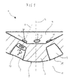
- Figure 1 shows an nozzle body 3 for a fluid injector 1 - which fluid injector 1 is in particular a fuel injector for a combustion engine - in a longitudinal section view.
- the nozzle body 3 comprises a wall 5 which forms a recess 7 and has a longitudinal axis L.
- a plurality of flow holes 9 penetrates the wall 5 from the recess 7 to an external surface 11 of the nozzle body 3 to enable a streaming fluid - which approaches the flow holes 9 in a flow direction D along an inner surface of the wall 5 - pass the nozzle body 3 during operation.
- the flow direction D in a region of the recess adjacent to the flow holes 9 is substantially directed in radial direction in top view along the longitudinal axis L.
- Each flow hole 9 comprises an inlet opening 15 which forms an entrance to each flow hole 9 and an outlet opening 13 which perforates the external surface 11 of the nozzle 3 and forms an exit of each flow hole 9.
- the hole axes H of the illustrated flow holes 9 are tilted and spatially shifted with respect to the longitudinal axis L to reduce a penetration of the fluid or a fluid spray into the outside 11 of a nozzle 3. Due to the longitudinal section view substantially, the tilt of the hole axes H of the flow holes 9 can only been illustrated in one plane.
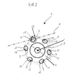
- the spatially displacement of the hole axes H of the flow holes 9 to the longitudinal axis L is illustrated in figure 2 and figure 3 which represent top view illustrations.
- the flow holes 9 are arranged in such a way that the longitudinal axis L and each hole axis H of the corresponding flow hole 9 do not intersect with another. In other words, the longitudinal axis L and the hole axes H are skew lines.
- the streaming fluid inside the nozzle 3 substantially flows in flow direction D until it enters the flow holes 9 by passing the corresponding inlet opening 15. Due to the tilt of the flow holes 9 the streaming fluid differs from the flow direction D not only in a vertical plane but also with an angle to it. Therefore, a swirling motion of the streaming fluid inside the flow holes 9 is induced and a transfer of axial kinetic energy to non-axial kinetic energy is initiated.
- the streaming fluid may substantially flow direction of the corresponding hole axis H of the respective flow hole 9 but also with a rotational velocity around each hole axis H.
- the hole axes H each extend tangential to an imaginary circle C centered on the longitudinal axis L and extending through the geometric centers of gravity of the flow holes 9.
- the non-axial kinetic energy of the streaming fluid in the flow holes 9 is particularly large wherein the axial kinetic energy is particularly small and as a consequence of this the penetration of the fluid or the fluid spray out of the nozzle 3 into the external surface 11 is particularly low.
- axial and non-axial kinetic energy refer to the hole axis H of the respective flow hole 9.
- the penetration of the fluid can be reduced from 77 mm to 66 mm compared to an assembly or injector with flow holes that extend obliquely to the longitudinal axis L and, in top view along the longitudinal axis L, in radial outward direction.
- the penetration is defined by a delay of 1.7 milliseconds after injection.
- the penetration of the fluid or the fluid spray into the external surface 11 of the nozzle 3 can be reduced about 11mm or 14%.
- the penetration of the fluid can be reduced from 68 mm to 62 mm, again the penetration is defined by a delay of 1.7 milliseconds after injection.
- the penetration of the fluid or the fluid spray can be reduced about 6 mm or 9% using the nozzle body 3 with flow holes 9 which extend skew to the longitudinal axis L.
- FIG. 2 shows an exemplary embodiment of the nozzle body 3 in a top view and illustrates a possible arrangement of the flow holes 9.
- This embodiment comprises six flow holes 9 arranged symmetrically and circularly around the longitudinal axis L. Specifically, the geometric centers of gravity of the flow holes 9 are evenly distributed on the circle C.
- Each flow hole 9 comprises one inlet opening 15 and one outlet opening 13 wherein the outlet openings 13 are radially and circumferentially offset with respect to the corresponding inlet opening 15of the respective flow hole 9.
- This presents one possible arrangement of the tilted flow holes 9 which may be advantageous for manufacturing because of the symmetrical positioning. But it is also possible that every second flow hole 9 is radially displaced by a predetermined value so that three flow holes 9 are arranged in one circle and the other three flow holes 9 are arranged in a second circle.
- the hole axes H of the flow holes 9 is tilted in two spatial dimensions with respect to the flow direction D or the longitudinal axis L.
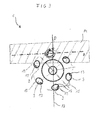
- FIG 3 the exemplary embodiment of the nozzle body 3 of figure 2 is shown once more in addition with a first plane P1 and a second plane P2.
- the first plane P1 is spanned by one hole axis H of one flow hole 9 and the flow direction D.
- the second plane P2 is spanned by the longitudinal axis L and the flow direction D.
- the second plane P2 substantially represents a vertical plane with respect to the longitudinal axis L as a vertical axis.
- the first plane P1 is no vertical plane because each hole axis H of one flow hole 9 is tilted in two spatial dimensions with respect to the longitudinal axis L and hence includes an angle to the second plane P2 that differs from zero.
- This exemplary embodiment shall illustrate that it is not possible to span a plane by any hole axis H of one flow hole 9 and the longitudinal axis L or the flow direction D due to the tilted flow holes 9 of the nozzle body 3.
Landscapes
- Engineering & Computer Science (AREA)
- Chemical & Material Sciences (AREA)
- Combustion & Propulsion (AREA)
- Mechanical Engineering (AREA)
- General Engineering & Computer Science (AREA)
- Fuel-Injection Apparatus (AREA)
Abstract
A nozzle body (3) for a fluid injector (1) is disclosed. It has a longitudinal central axis (L) and comprises a wall (5) which forms a recess (7) for accommodating fluid. At least one flow hole (9) penetrates the wall (5) from the recess (7) to an external surface (11) of the nozzle body (3) to enable dispensing of fluid from the nozzle body (3). The at least one flow hole (9) has a hole axis (H) which is skew with respect to the longitudinal axis (L). Further, a fluid injector (1) with the nozzle body (3) is disclosed.
Description
- The invention relates to a nozzle body for a fluid injector wherein one or more flow holes of an injector are specifically orientated and to a fluid injector with the nozzle body.
- Injectors are in widespread use, in particular for combustion engines where they may be arranged in order to dose a fluid into an intake manifold of the combustion engine or directly into a combustion chamber of a cylinder of the combustion engine.
- In general an injector has one or several flow holes to dispense a fluid, for example to generate a fluid spray in a combustion chamber of a combustion engine. In this context, a penetration of the fluid spray inside the combustion chamber is an important parameter to control the function of the injector and the combustion engine. Thereby, the penetration of the fluid or the fluid spray describes a distance that is covered by the fluid for example with respect to a longitudinal axis after a specified delay from a starting point of injection.
- It is important to keep the penetration of the fluid spray low for example to avoid impingement of the fluid with walls of the combustion chamber of the combustion engine. Therefore, there are several geometric parameters to control the penetration, two of these are the length over diameter ratio and the hole taper of the flow holes of the injector. In comparison, the taper of the flow holes has a lower effect than the length over diameter ratio because the diameter is imposed by the fluid flow and the length is limited by the structural resistance of the injector. For this reason low penetration with enough thickness of injector walls is a desirable and demanding requirement.
- One object of the invention is to create an nozzle body for a fluid injector to reduce a penetration of a fluid spray of an injector.
- The object is achieved by the features of the independent claim. Advantageous embodiments of the invention are given in the dependent claims.
- The invention makes use of the idea that the penetration of a fluid spray strongly depends from the non-axial turbulent kinetic energy of the fluid. The higher non-axial turbulent kinetic energy, the lower the penetration, due to the fact that non-axial kinetic energy is not directed in direction of penetration but in direction tangential to it which is advantageous for atomization of the fluid which is e.g. fuel.
- According to a first aspect of the invention a nozzle body for a fluid injector is disclosed. According to a second aspect, a fluid injector is disclosed which comprises the nozzle body. In particular, the nozzle body is arranged at a fluid outlet end of a valve body of the injector or in one piece with the valve body.
- The nozzle body has a longitudinal axis, which is in particular also a longitudinal axis of the valve body. The nozzle body comprises a wall which forms a recess which is in particular configured for accommodating fluid. At least one flow hole penetrates the wall from the recess to an external surface of the nozzle body, in particular to enable a streaming fluid pass the assembly during an operation. In other words, fluid is dispensable from the nozzle body or the fluid injector, respectively, through the flow hole(s). The flow hole or each flow hole has a hole axis which is tilted with respect to the longitudinal axis and which extends completely spatially displaced to the longitudinal axis to reduce a penetration of the fluid into the external surface of the nozzle. In other words, the hole axis or each of the hole axes extends skew with respect to the longitudinal axis, i.e. it is not parallel to the longitudinal axis and does not intersect the longitudinal axis.
- This configuration of the nozzle body for a fluid injector describes a simple and reliable possibility to reduce the penetration of the fluid and the resulting fluid spray, for example of an injector inside a combustion chamber and hence enables an improved combustion process. The reduction of the penetration is achieved by arranging the one or more flow holes tilted and spatially shifted with respect to the longitudinal axis.
- Hence, the hole axis of the at least one flow hole and the longitudinal axis of the nozzle are arranged in such a way that there is no intersection between the hole axis and the longitudinal axis. In other words, it is not possible to span a plane by the hole axis and the longitudinal axis because these axes describe skew lines. Such a described arrangement of the at least one flow hole increases the non-axial kinetic energy of the streaming fluid by inducing a tangential velocity to it inside the at least one flow hole.
- In this context, a projection of the hole axis of the one or more flow holes onto a top view plane of a top view along the longitudinal axis is directed with an angle at least greater than zero and, for example, close to 90° to a the respective projection of a flow direction of the streaming fluid inside the recess. In this context, the flow direction substantially follows an inner surface of the wall - which inner surface defines the recess - in radial inward direction in the course along the longitudinal axis of the assembly inside the recess of the nozzle and substantially follows the hole axis inside the one or more flow holes. Therefore, a projection of the hole axis or each of the hole axes as seen in top view along the longitudinal axis preferably extends tangentially to an (imaginary) circle around the longitudinal axis. The circle is perpendicular to the longitudinal axis, centered on the longitudinal axis and overlaps with the respective flow hole, in particular with a geometric center of gravity thereof. In this way, the streaming fluid gets a particular large rotation velocity around each hole axis when it enters the respective flow hole. This decreases the axial energy and increases the non-axial kinetic energy of the streaming fluid. This transfer of kinetic energy is well-founded by the specifically orientation of the at least one flow hole with respect to the longitudinal axis or the flow direction of the injector.
- Using the presented assembly it is not necessary to push other geometry parameters to the limit, for example the length to diameter ratio of the nozzle or the hole taper of the flow hole for example. The described orientation of the one or more flow holes is an additional step to further reduce the penetration of fluid significantly and keeping the possibility to use other driving parameters in parallel. For example, if a required penetration is reached using one embodiment of the assembly higher length over diameter ratio can be realized which can be beneficial for structural resistance of the assembly.
- According to oneembodiment, the nozzle body comprises two or more flow holes which are circumferentially distributed around the longitudinal axis. In particular the geometric centers of gravity of the flow holes are positioned on an imaginary circle around the longitudinal axis and preferably evenly spaced. Particularly preferably, the flow holes are distributed in such fashion around the longitudinal axis that the nozzle body has an n-fold rotational symmetry - at least with regard to the flow holes - with respect to the longitudinal axis, n being the number of flow holes. In this context, an n-fold rotational symmetry - also referred to as a rotational symmetry of order n or a discrete rotational symmetry of the n-th order - with respect to a particular axis means that rotation by an angle of 360°/n does not change the object having the symmetry.
- The positioning of the flow holes inside the nozzle enables a symmetrical fluid entrance and fluid exit of the streaming fluid during an operation of the assembly or a corresponding injector and hence enables a symmetrical fluid spray out of the nozzle during an operation of the assembly. This may be advantageous for a combustion process inside a combustion chamber of a combustion engine, for example.
- According to a further embodiment, an outlet opening of the at least one flow hole is offset in radial and/or circumferential direction with respect to the longitudinal axis relative to an inlet opening of the flow hole. An offset in circumferential direction may also be denoted as an angular offset, referring in particular to a rotation around the longitudinal axis.
- This embodiment of the invention describes a possible geometry of the tilted flow hole with respect to the longitudinal axis of the assembly and realizes in a simple and competitive way a reduction of the penetration of the fluid or the fluid spray out of the nozzle. For example, the one or more flow holes are drilled inclined into the nozzle of the assembly with specific and predetermined angle values in two spatial dimensions with respect to the longitudinal axis or the flow direction.
- According to a further embodiment of the first aspect the two or more flow holes are circularly arranged around the longitudinal axis.
- Exemplary embodiments of the invention are explained in the following with the aid of schematic drawings and reference numbers. Identical reference numbers designate elements or components with identical functions. The figures show:
- Figure 1
- a nozzle body for a fluid injector;
- Figure 2
- a top view of a nozzle body for a fluid injector; and
- Figure 3
- a further top view of the nozzle body.
-
Figure 1 shows annozzle body 3 for a fluid injector 1 - whichfluid injector 1 is in particular a fuel injector for a combustion engine - in a longitudinal section view. - The
nozzle body 3 comprises awall 5 which forms a recess 7 and has a longitudinal axis L. - A plurality of
flow holes 9 penetrates thewall 5 from the recess 7 to anexternal surface 11 of thenozzle body 3 to enable a streaming fluid - which approaches theflow holes 9 in a flow direction D along an inner surface of the wall 5 - pass thenozzle body 3 during operation. For example, the flow direction D in a region of the recess adjacent to theflow holes 9 is substantially directed in radial direction in top view along the longitudinal axis L. Eachflow hole 9 comprises aninlet opening 15 which forms an entrance to eachflow hole 9 and an outlet opening 13 which perforates theexternal surface 11 of thenozzle 3 and forms an exit of eachflow hole 9. - The hole axes H of the illustrated
flow holes 9 are tilted and spatially shifted with respect to the longitudinal axis L to reduce a penetration of the fluid or a fluid spray into theoutside 11 of anozzle 3. Due to the longitudinal section view substantially, the tilt of the hole axes H of theflow holes 9 can only been illustrated in one plane. The spatially displacement of the hole axes H of theflow holes 9 to the longitudinal axis L is illustrated infigure 2 andfigure 3 which represent top view illustrations. Hence, the flow holes 9 are arranged in such a way that the longitudinal axis L and each hole axis H of thecorresponding flow hole 9 do not intersect with another. In other words, the longitudinal axis L and the hole axes H are skew lines. - This tilt and spatial displacement of the hole axes H of the flow holes 9 with respect to the longitudinal axis L lead to a transfer of axial kinetic energy of the streaming fluid to non-axial kinetic energy during an operation of the
nozzle body 3. The streaming fluid inside thenozzle 3 substantially flows in flow direction D until it enters the flow holes 9 by passing thecorresponding inlet opening 15. Due to the tilt of the flow holes 9 the streaming fluid differs from the flow direction D not only in a vertical plane but also with an angle to it. Therefore, a swirling motion of the streaming fluid inside the flow holes 9 is induced and a transfer of axial kinetic energy to non-axial kinetic energy is initiated. The streaming fluid may substantially flow direction of the corresponding hole axis H of therespective flow hole 9 but also with a rotational velocity around each hole axis H. - In top view along the longitudinal axis L, the hole axes H each extend tangential to an imaginary circle C centered on the longitudinal axis L and extending through the geometric centers of gravity of the flow holes 9. As a result, the non-axial kinetic energy of the streaming fluid in the flow holes 9 is particularly large wherein the axial kinetic energy is particularly small and as a consequence of this the penetration of the fluid or the fluid spray out of the
nozzle 3 into theexternal surface 11 is particularly low. In this context, axial and non-axial kinetic energy refer to the hole axis H of therespective flow hole 9. - This makes a contribution to less impingement of the fluid spray, for example with walls of a combustion chamber. Furthermore, the transferred kinetic energy on the one hand is useful to avoid impingement and on the other hand it is beneficial for atomization of the fluid, for example inside a combustion chamber. Hence, this is advantageous for a combustion process of a combustion engine.
- In this context, samples of the mentioned
nozzle body 3 have been built to prove the described configuration and have given promising results and have shown the reliable functioning of such anozzle body 3 with one or more tilted flow holes 9. - Using a fluid pressure of 200 bar and the
nozzle body 3 withflow holes 9 being skew with respect to the longitudinal axis L, the penetration of the fluid can be reduced from 77 mm to 66 mm compared to an assembly or injector with flow holes that extend obliquely to the longitudinal axis L and, in top view along the longitudinal axis L, in radial outward direction. In this context, the penetration is defined by a delay of 1.7 milliseconds after injection. Hence, the penetration of the fluid or the fluid spray into theexternal surface 11 of thenozzle 3 can be reduced about 11mm or 14%. - Using a fluid pressure of 100 bar the penetration of the fluid can be reduced from 68 mm to 62 mm, again the penetration is defined by a delay of 1.7 milliseconds after injection. Hence, the penetration of the fluid or the fluid spray can be reduced about 6 mm or 9% using the
nozzle body 3 withflow holes 9 which extend skew to the longitudinal axis L. -
Figure 2 shows an exemplary embodiment of thenozzle body 3 in a top view and illustrates a possible arrangement of the flow holes 9. This embodiment comprises sixflow holes 9 arranged symmetrically and circularly around the longitudinal axis L. Specifically, the geometric centers of gravity of the flow holes 9 are evenly distributed on the circle C. Eachflow hole 9 comprises oneinlet opening 15 and oneoutlet opening 13 wherein theoutlet openings 13 are radially and circumferentially offset with respect to the corresponding inlet opening 15of therespective flow hole 9. This presents one possible arrangement of the tiltedflow holes 9 which may be advantageous for manufacturing because of the symmetrical positioning. But it is also possible that everysecond flow hole 9 is radially displaced by a predetermined value so that threeflow holes 9 are arranged in one circle and the other threeflow holes 9 are arranged in a second circle. - It is also possible that there are more or less than six
flow holes 9 arranged in thewall 5 of thenozzle body 3 as long as the one ormore flow hole 9 is tilted in two spatial dimensions with respect to the longitudinal axis L and the flow direction D - i.e. has a hole axis H which extends skew to the longitudinal axis L - and hence enables the reduction of the penetration of the fluid. - In combination with the exemplary embodiment of
figure 1 it is conceivable that the hole axes H of the flow holes 9 is tilted in two spatial dimensions with respect to the flow direction D or the longitudinal axis L. - In
figure 3 the exemplary embodiment of thenozzle body 3 offigure 2 is shown once more in addition with a first plane P1 and a second plane P2. The first plane P1 is spanned by one hole axis H of oneflow hole 9 and the flow direction D. The second plane P2 is spanned by the longitudinal axis L and the flow direction D. - In reference to the top view of
figure 3 the second plane P2 substantially represents a vertical plane with respect to the longitudinal axis L as a vertical axis. The first plane P1 is no vertical plane because each hole axis H of oneflow hole 9 is tilted in two spatial dimensions with respect to the longitudinal axis L and hence includes an angle to the second plane P2 that differs from zero. - This exemplary embodiment shall illustrate that it is not possible to span a plane by any hole axis H of one
flow hole 9 and the longitudinal axis L or the flow direction D due to the tiltedflow holes 9 of thenozzle body 3.
Claims (7)
- Nozzle body (3) for a fluid injector (1)
wherein- the nozzle body (3) has a longitudinal central axis (L) and comprises a wall (5) which forms a recess (7) for accommodating fluid,- at least one flow hole (9) penetrates the wall (5) from the recess (7) to an external surface (11) of the nozzle body (3) to enable dispensing of fluid from the nozzle body (3), and- the at least one flow hole (9) has a hole axis (H) which is skew with respect to the longitudinal axis (L). - Nozzle body (3) in accordance with claim 1, wherein comprising two or more flow holes (9) which are circumferentially distributed around the longitudinal axis (L).
- Nozzle body (3) in accordance with claim 2, wherein the flow holes (9) are distributed in such fashion around the longitudinal axis that the nozzle body has an n-fold rotational symmetry, n being the number of flow holes (9).
- Nozzle body (3) in accordance with one of the preceding claims, wherein an outlet opening (13) of the at least one flow hole (9) is radially and/or angularly offset relative to an inlet opening (15) of the at least one flow hole (9) in reference to the longitudinal axis (L).
- Nozzle body (3) in accordance with one of the preceding claims, wherein a projection of the hole axis (H) as seen in top view along the longitudinal axis (L) extends tangentially to a circle around the longitudinal axis (L) which circle is perpendicular to the longitudinal axis (L), centered on the longitudinal axis (L) and overlaps with the flow hole (9).
- Nozzle body (3) in accordance with one of the preceding claims, wherein the flow holes (9) are circularly arranged around the longitudinal axis (L).
- Fluid injector (1) comprising the nozzle body (3) according one of the preceding claims.
Priority Applications (1)
| Application Number | Priority Date | Filing Date | Title |
|---|---|---|---|
| EP14189019.4A EP3009662A1 (en) | 2014-10-15 | 2014-10-15 | Nozzle body for a fluid injector and fluid injector |
Applications Claiming Priority (1)
| Application Number | Priority Date | Filing Date | Title |
|---|---|---|---|
| EP14189019.4A EP3009662A1 (en) | 2014-10-15 | 2014-10-15 | Nozzle body for a fluid injector and fluid injector |
Publications (1)
| Publication Number | Publication Date |
|---|---|
| EP3009662A1 true EP3009662A1 (en) | 2016-04-20 |
Family
ID=51690971
Family Applications (1)
| Application Number | Title | Priority Date | Filing Date |
|---|---|---|---|
| EP14189019.4A Withdrawn EP3009662A1 (en) | 2014-10-15 | 2014-10-15 | Nozzle body for a fluid injector and fluid injector |
Country Status (1)
| Country | Link |
|---|---|
| EP (1) | EP3009662A1 (en) |
Citations (10)
| Publication number | Priority date | Publication date | Assignee | Title |
|---|---|---|---|---|
| DE972387C (en) * | 1953-04-15 | 1959-07-09 | Daimler Benz Ag | Fuel injection nozzle with swirl effect |
| DE3012416A1 (en) * | 1980-03-29 | 1981-10-15 | Robert Bosch Gmbh, 7000 Stuttgart | Fuel-injection valve with capillary channel - which prevents gas reaching metering point and forming deposits reducing cross=section |
| EP1195515A2 (en) * | 2000-10-04 | 2002-04-10 | Robert Bosch Gmbh | Fuel injector |
| US20030141385A1 (en) * | 2002-01-31 | 2003-07-31 | Min Xu | Fuel injector swirl nozzle assembly |
| JP2005233145A (en) * | 2004-02-23 | 2005-09-02 | Denso Corp | Fuel injection valve |
| EP2505820A1 (en) * | 2011-03-31 | 2012-10-03 | KW Technologie GmbH & Co. KG | Device for turning a liquid in a combustion chamber into a fog or spray |
| JP2013194725A (en) * | 2012-03-23 | 2013-09-30 | Hitachi Automotive Systems Ltd | Fuel injection valve |
| US20130255622A1 (en) * | 2012-03-30 | 2013-10-03 | Deep Bandyopadhyay | Nozzle for skewed fuel injection |
| WO2014052126A1 (en) * | 2012-09-25 | 2014-04-03 | Achates Power, Inc. | Fuel injection with swirl spray patterns in opposed-piston engines |
| DE112011105496T5 (en) * | 2011-08-03 | 2014-04-24 | Hitachi Automotive Systems, Ltd. | Fuel injection valve |
-
2014
- 2014-10-15 EP EP14189019.4A patent/EP3009662A1/en not_active Withdrawn
Patent Citations (10)
| Publication number | Priority date | Publication date | Assignee | Title |
|---|---|---|---|---|
| DE972387C (en) * | 1953-04-15 | 1959-07-09 | Daimler Benz Ag | Fuel injection nozzle with swirl effect |
| DE3012416A1 (en) * | 1980-03-29 | 1981-10-15 | Robert Bosch Gmbh, 7000 Stuttgart | Fuel-injection valve with capillary channel - which prevents gas reaching metering point and forming deposits reducing cross=section |
| EP1195515A2 (en) * | 2000-10-04 | 2002-04-10 | Robert Bosch Gmbh | Fuel injector |
| US20030141385A1 (en) * | 2002-01-31 | 2003-07-31 | Min Xu | Fuel injector swirl nozzle assembly |
| JP2005233145A (en) * | 2004-02-23 | 2005-09-02 | Denso Corp | Fuel injection valve |
| EP2505820A1 (en) * | 2011-03-31 | 2012-10-03 | KW Technologie GmbH & Co. KG | Device for turning a liquid in a combustion chamber into a fog or spray |
| DE112011105496T5 (en) * | 2011-08-03 | 2014-04-24 | Hitachi Automotive Systems, Ltd. | Fuel injection valve |
| JP2013194725A (en) * | 2012-03-23 | 2013-09-30 | Hitachi Automotive Systems Ltd | Fuel injection valve |
| US20130255622A1 (en) * | 2012-03-30 | 2013-10-03 | Deep Bandyopadhyay | Nozzle for skewed fuel injection |
| WO2014052126A1 (en) * | 2012-09-25 | 2014-04-03 | Achates Power, Inc. | Fuel injection with swirl spray patterns in opposed-piston engines |
Similar Documents
| Publication | Publication Date | Title |
|---|---|---|
| US9982584B2 (en) | Device for the aftertreatment of exhaust gas from a motor vehicle | |
| JP5668984B2 (en) | Fuel injection device | |
| US7810745B2 (en) | Nozzle device and fuel injection valve having the same | |
| US20150047611A1 (en) | Spark-ignition direct fuel injection valve | |
| JP5772495B2 (en) | Fuel injection valve | |
| US10774800B2 (en) | Nozzle body and fuel injection valve | |
| JP2016217245A (en) | Injector | |
| US8657213B2 (en) | Fuel injection valve | |
| CN103282644A (en) | Injection valve | |
| EP2626626A2 (en) | Improved liquid fuel swirler | |
| JP2018080670A (en) | Injector | |
| EP2808533B1 (en) | Fuel injector | |
| WO2015011539A1 (en) | Fuel injection valve | |
| JP5976065B2 (en) | Fuel injection valve | |
| JP5943060B2 (en) | Fuel injection device | |
| JP2015523501A (en) | Directing fuel discharge by directing the flow out of the nozzle off-axis | |
| WO2018099875A1 (en) | Piston crown | |
| EP2333307A1 (en) | Fuel injection valve for internal combustion engine and method of manufacturing the same | |
| EP2749762A1 (en) | Fuel injection valve | |
| EP2677158B1 (en) | Fuel injector of internal combustion engine | |
| JP6023151B2 (en) | Fuel injection valve | |
| EP3189220B1 (en) | Multicylinder internal combustion engine with exhaust manifold | |
| JP6154362B2 (en) | Fuel injection nozzle | |
| JP7020662B2 (en) | Multiple injection hole structure of liquid injection nozzle | |
| JP2012013086A (en) | Pump for dosing fluid |
Legal Events
| Date | Code | Title | Description |
|---|---|---|---|
| PUAI | Public reference made under article 153(3) epc to a published international application that has entered the european phase |
Free format text: ORIGINAL CODE: 0009012 |
|
| AK | Designated contracting states |
Kind code of ref document: A1 Designated state(s): AL AT BE BG CH CY CZ DE DK EE ES FI FR GB GR HR HU IE IS IT LI LT LU LV MC MK MT NL NO PL PT RO RS SE SI SK SM TR |
|
| AX | Request for extension of the european patent |
Extension state: BA ME |
|
| STAA | Information on the status of an ep patent application or granted ep patent |
Free format text: STATUS: THE APPLICATION IS DEEMED TO BE WITHDRAWN |
|
| 18D | Application deemed to be withdrawn |
Effective date: 20161021 |