EP3009631A1 - Engine control device - Google Patents
Engine control device Download PDFInfo
- Publication number
- EP3009631A1 EP3009631A1 EP14811126.3A EP14811126A EP3009631A1 EP 3009631 A1 EP3009631 A1 EP 3009631A1 EP 14811126 A EP14811126 A EP 14811126A EP 3009631 A1 EP3009631 A1 EP 3009631A1
- Authority
- EP
- European Patent Office
- Prior art keywords
- engine
- opening
- temperature
- waste gate
- gate valve
- Prior art date
- Legal status (The legal status is an assumption and is not a legal conclusion. Google has not performed a legal analysis and makes no representation as to the accuracy of the status listed.)
- Granted
Links
Images


Classifications
-
- F—MECHANICAL ENGINEERING; LIGHTING; HEATING; WEAPONS; BLASTING
- F02—COMBUSTION ENGINES; HOT-GAS OR COMBUSTION-PRODUCT ENGINE PLANTS
- F02B—INTERNAL-COMBUSTION PISTON ENGINES; COMBUSTION ENGINES IN GENERAL
- F02B37/00—Engines characterised by provision of pumps driven at least for part of the time by exhaust
- F02B37/12—Control of the pumps
- F02B37/18—Control of the pumps by bypassing exhaust from the inlet to the outlet of turbine or to the atmosphere
- F02B37/183—Arrangements of bypass valves or actuators therefor
- F02B37/186—Arrangements of actuators or linkage for bypass valves
-
- F—MECHANICAL ENGINEERING; LIGHTING; HEATING; WEAPONS; BLASTING
- F02—COMBUSTION ENGINES; HOT-GAS OR COMBUSTION-PRODUCT ENGINE PLANTS
- F02B—INTERNAL-COMBUSTION PISTON ENGINES; COMBUSTION ENGINES IN GENERAL
- F02B37/00—Engines characterised by provision of pumps driven at least for part of the time by exhaust
- F02B37/12—Control of the pumps
- F02B37/16—Control of the pumps by bypassing charging air
-
- F—MECHANICAL ENGINEERING; LIGHTING; HEATING; WEAPONS; BLASTING
- F02—COMBUSTION ENGINES; HOT-GAS OR COMBUSTION-PRODUCT ENGINE PLANTS
- F02B—INTERNAL-COMBUSTION PISTON ENGINES; COMBUSTION ENGINES IN GENERAL
- F02B37/00—Engines characterised by provision of pumps driven at least for part of the time by exhaust
- F02B37/12—Control of the pumps
- F02B37/18—Control of the pumps by bypassing exhaust from the inlet to the outlet of turbine or to the atmosphere
-
- F—MECHANICAL ENGINEERING; LIGHTING; HEATING; WEAPONS; BLASTING
- F02—COMBUSTION ENGINES; HOT-GAS OR COMBUSTION-PRODUCT ENGINE PLANTS
- F02B—INTERNAL-COMBUSTION PISTON ENGINES; COMBUSTION ENGINES IN GENERAL
- F02B39/00—Component parts, details, or accessories relating to, driven charging or scavenging pumps, not provided for in groups F02B33/00 - F02B37/00
- F02B39/02—Drives of pumps; Varying pump drive gear ratio
- F02B39/08—Non-mechanical drives, e.g. fluid drives having variable gear ratio
- F02B39/10—Non-mechanical drives, e.g. fluid drives having variable gear ratio electric
-
- F—MECHANICAL ENGINEERING; LIGHTING; HEATING; WEAPONS; BLASTING
- F02—COMBUSTION ENGINES; HOT-GAS OR COMBUSTION-PRODUCT ENGINE PLANTS
- F02D—CONTROLLING COMBUSTION ENGINES
- F02D23/00—Controlling engines characterised by their being supercharged
-
- F—MECHANICAL ENGINEERING; LIGHTING; HEATING; WEAPONS; BLASTING
- F02—COMBUSTION ENGINES; HOT-GAS OR COMBUSTION-PRODUCT ENGINE PLANTS
- F02D—CONTROLLING COMBUSTION ENGINES
- F02D35/00—Controlling engines, dependent on conditions exterior or interior to engines, not otherwise provided for
- F02D35/02—Controlling engines, dependent on conditions exterior or interior to engines, not otherwise provided for on interior conditions
- F02D35/025—Controlling engines, dependent on conditions exterior or interior to engines, not otherwise provided for on interior conditions by determining temperatures inside the cylinder, e.g. combustion temperatures
-
- F—MECHANICAL ENGINEERING; LIGHTING; HEATING; WEAPONS; BLASTING
- F02—COMBUSTION ENGINES; HOT-GAS OR COMBUSTION-PRODUCT ENGINE PLANTS
- F02D—CONTROLLING COMBUSTION ENGINES
- F02D41/00—Electrical control of supply of combustible mixture or its constituents
- F02D41/0002—Controlling intake air
- F02D41/0007—Controlling intake air for control of turbo-charged or super-charged engines
-
- F—MECHANICAL ENGINEERING; LIGHTING; HEATING; WEAPONS; BLASTING
- F02—COMBUSTION ENGINES; HOT-GAS OR COMBUSTION-PRODUCT ENGINE PLANTS
- F02D—CONTROLLING COMBUSTION ENGINES
- F02D41/00—Electrical control of supply of combustible mixture or its constituents
- F02D41/02—Circuit arrangements for generating control signals
- F02D41/021—Introducing corrections for particular conditions exterior to the engine
- F02D41/0235—Introducing corrections for particular conditions exterior to the engine in relation with the state of the exhaust gas treating apparatus
- F02D41/024—Introducing corrections for particular conditions exterior to the engine in relation with the state of the exhaust gas treating apparatus to increase temperature of the exhaust gas treating apparatus
- F02D41/0255—Introducing corrections for particular conditions exterior to the engine in relation with the state of the exhaust gas treating apparatus to increase temperature of the exhaust gas treating apparatus to accelerate the warming-up of the exhaust gas treating apparatus at engine start
-
- F—MECHANICAL ENGINEERING; LIGHTING; HEATING; WEAPONS; BLASTING
- F02—COMBUSTION ENGINES; HOT-GAS OR COMBUSTION-PRODUCT ENGINE PLANTS
- F02D—CONTROLLING COMBUSTION ENGINES
- F02D41/00—Electrical control of supply of combustible mixture or its constituents
- F02D41/02—Circuit arrangements for generating control signals
- F02D41/04—Introducing corrections for particular operating conditions
- F02D41/06—Introducing corrections for particular operating conditions for engine starting or warming up
- F02D41/062—Introducing corrections for particular operating conditions for engine starting or warming up for starting
- F02D41/064—Introducing corrections for particular operating conditions for engine starting or warming up for starting at cold start
-
- F—MECHANICAL ENGINEERING; LIGHTING; HEATING; WEAPONS; BLASTING
- F01—MACHINES OR ENGINES IN GENERAL; ENGINE PLANTS IN GENERAL; STEAM ENGINES
- F01N—GAS-FLOW SILENCERS OR EXHAUST APPARATUS FOR MACHINES OR ENGINES IN GENERAL; GAS-FLOW SILENCERS OR EXHAUST APPARATUS FOR INTERNAL COMBUSTION ENGINES
- F01N3/00—Exhaust or silencing apparatus having means for purifying, rendering innocuous, or otherwise treating exhaust
- F01N3/08—Exhaust or silencing apparatus having means for purifying, rendering innocuous, or otherwise treating exhaust for rendering innocuous
- F01N3/10—Exhaust or silencing apparatus having means for purifying, rendering innocuous, or otherwise treating exhaust for rendering innocuous by thermal or catalytic conversion of noxious components of exhaust
- F01N3/101—Three-way catalysts
-
- Y—GENERAL TAGGING OF NEW TECHNOLOGICAL DEVELOPMENTS; GENERAL TAGGING OF CROSS-SECTIONAL TECHNOLOGIES SPANNING OVER SEVERAL SECTIONS OF THE IPC; TECHNICAL SUBJECTS COVERED BY FORMER USPC CROSS-REFERENCE ART COLLECTIONS [XRACs] AND DIGESTS
- Y02—TECHNOLOGIES OR APPLICATIONS FOR MITIGATION OR ADAPTATION AGAINST CLIMATE CHANGE
- Y02T—CLIMATE CHANGE MITIGATION TECHNOLOGIES RELATED TO TRANSPORTATION
- Y02T10/00—Road transport of goods or passengers
- Y02T10/10—Internal combustion engine [ICE] based vehicles
- Y02T10/12—Improving ICE efficiencies
Definitions
- This invention relates to a control apparatus of an engine equipped with a waste gate valve for adjusting a boost pressure by a supercharger such as a turbocharger.
- Patent Document 1 JP-A-2012-97714
- Start-up of an engine (internal combustion engine) loaded on a vehicle, such as an automobile, is performed by cranking the engine, for example, in response to a start-up request by the operation of a starting switch such as an ignition switch.
- a starting switch such as an ignition switch.
- it is effective to increase the engine speed by cranking.
- the startability of the engine can be improved by increasing the engine speed by cranking.
- an engine body, a catalyst, and an air-fuel ratio sensor can be warmed up early, and a stable operation after starting and exhaust gas amelioration can also be realized.
- the present invention has been accomplished in the light of the above circumstances. It is an object of the invention to provide a control apparatus of an engine which, for example, can enhance the startability of the engine even in extremely cold starting, can also achieve a stable operation after starting, and can further ameliorate an exhaust gas at an early stage.
- a first aspect of the present invention for solving the above problems, is a control apparatus of an engine having an exhaust bypass passage for bypassing a turbine of a supercharger, and a waste gate valve for opening and closing the exhaust bypass passage, the control apparatus comprising: an opening/closing control means for controlling the opening/closing action of the waste gate valve; and a start-up control means for starting up the engine in accordance with an engine start-up request, wherein the opening/closing control means controls the opening/closing action of the waste gate valve in accordance with the temperature of the engine before a start-up procedure for the engine by the start-up control means is started and, if the temperature of the engine is equal to or lower than a first set temperature, controls the waste gate valve in a valve opening direction.
- a second aspect of the present invention is the control apparatus of an engine according to the first aspect, wherein the opening/closing control means controls the opening/closing action of the waste gate valve in accordance with the temperature of the engine after the start-up procedure for the engine is completed and, if the temperature of the engine is equal to or lower than a second set temperature, controls the waste gate valve in a valve closing direction.
- a third aspect of the present invention is the control apparatus of an engine according to the second aspect, wherein the first set temperature is set to be lower than the second set temperature.
- a fourth aspect of the present invention is the control apparatus of an engine according to the third aspect, wherein if the temperature of the engine is equal to or lower than the second set temperature after the start-up procedure for the engine is completed, the opening/closing control means maintains the waste gate valve in a closed state until the temperature of the engine becomes equal to or higher than a third set temperature which is higher than the second set temperature, but lower than the warm-up completion temperature of the engine.
- a fifth aspect of the present invention is the control apparatus of an engine according to any one of the first to fourth aspects, wherein the engine has an intake bypass valve for opening and closing an intake bypass passage for bypassing a compressor of the supercharger, and the opening/closing control means controls the opening/closing action of the intake bypass valve as well as the opening/closing action of the waste gate valve and, in controlling the waste gate valve in the valve opening direction, also controls the intake bypass valve in a valve opening direction.
- a sixth aspect of the present invention is the control apparatus of an engine according to any one of the first to fifth aspects, wherein the waste gate valve has an actuator which works for valve closing by use of electric power supplied from a battery, and works for valve opening upon a cutoff of the electric power supplied from the battery, and the start-up control means actuates an electric motor for cranking the engine by use of the electric power supplied from the battery.
- an engine body 11 constituting the engine 10 has a cylinder head 12 and a cylinder block 13, and a piston 14 is accommodated within the cylinder block 13.
- the piston 14 is connected to a crankshaft 16 via a connecting rod 15.
- the piston 14, the cylinder head 12, and the cylinder block 13 form a combustion chamber 17.
- An intake port 18 is formed in the cylinder head 12, and an intake pipe (intake passage) 20 including an intake manifold 19 is connected to the intake port 18.
- the intake pipe 20 is provided with an intake pressure sensor (MAP sensor) 21 for detecting an intake pressure, and an intake temperature sensor 22 for detecting the temperature of intake air.
- MAP sensor intake pressure sensor
- An intake valve 23 is also provided inside the intake port 18, and the intake port 18 is opened and closed with the intake valve 23. That is, the intake valve 23 is adapted to act following an intake cam 24a of an intake camshaft 24 rotating in accordance with an engine revolution, thereby allowing the combustion chamber 17 and the intake port 18 to communicate with each other and to be cut off from each other.
- an exhaust port 25 is formed in the cylinder head 12, and an exhaust pipe (exhaust passage) 27 including an exhaust manifold 26 is connected to the interior of the exhaust port 25.
- An exhaust valve 28 is provided in the exhaust port 25 and, as does the intake valve 23 in the intake port 18, the exhaust valve 28 is adapted to act following an exhaust cam 29a of an exhaust camshaft 29, thereby allowing the combustion chamber 17 and the exhaust port 25 to communicate with each other and to be cut off from each other.
- the exhaust port 25 and the exhaust manifold 26 are constituted inside the cylinder head 12.
- the exhaust manifold 26 is equipped with an exhaust collecting section (not shown), and the exhaust collecting section is connected to a turbine 32a of a turbocharger 32 (to be described later) via an exhaust flange of the cylinder head 12.
- the engine body 11 is provided with a fuel injection valve 30 for injecting fuel into the combustion chamber 17 of each cylinder.
- the fuel injection valve 30 is supplied with fuel from high pressure fuel delivery piping, although this is not shown.
- the high pressure fuel delivery piping is supplied with fuel, which has been supplied from a low pressure fuel pump within a fuel tank, while being pressurized to a predetermined pressure by a high pressure fuel pump.
- the cylinder head 12 is further mounted with a spark plug 31 for each cylinder.
- the turbocharger 32 a supercharger, is provided halfway between the intake pipe 20 and the exhaust pipe 27.
- the turbocharger 32 has the turbine 32a and a compressor 32b, and the turbine 32a and the compressor 32b are coupled together by a turbine shaft 32c.
- the turbine 32a When an exhaust gas flows into the turbocharger 32, the turbine 32a is rotated by the flow of the exhaust gas and, in accordance with the rotation of the turbine 32a, the compressor 32b is rotated.
- Air (intake air) pressurized by the rotation of the compressor 32b is sent out into the intake pipe 20, and supplied to each intake port 18.
- An intercooler 33 is provided at a portion of the intake pipe 20 downstream of the turbocharger 32, and a throttle valve 34 is provided downstream of the intercooler 33.
- An upstream side and a downstream side of the exhaust pipe 27, with the turbocharger 32 being interposed therebetween, are connected together by an exhaust bypass passage 35. That is, the exhaust bypass passage 35 is a passage for bypassing the turbine 32a of the turbocharger 32.
- a waste gate valve (WGV) 36 is provided in the exhaust bypass passage 35.
- the waste gate valve (WGV) 36 is equipped with a valve body 36a, and an electrically operated actuator 36b for driving the valve body 36a, and the amount of the exhaust gas flowing through the exhaust bypass passage 35 can be adjusted depending on the opening of the valve body 36a. That is, the waste gate valve 36 is configured to be capable of adjusting the boost pressure of the turbocharger 32 by adjustment of its opening.
- the structure of the waste gate valve 36 may rely on conventional technologies, and may be a structure for maintaining a valve closing state by a spring or the like, for example, as described in JP-A-2006-274831 .
- the present embodiment does not use a spring for maintaining the valve closing state, but adopts a structure for maintaining the valve closing state by driving the electric actuator 36b (see JP-A-2012-62803 ). While the valve closing state is being maintained, therefore, electric power is consumed by the actuator 36b.
- an intake bypass passage 37 is a passage for bypassing the compressor 32b of the turbocharger 32.
- an intake bypass valve 38 is provided for opening and closing the intake bypass passage 37.
- the configuration of the intake bypass valve 38 is not limited, but in the present embodiment, is a configuration equipped with a valve body and an actuator, as is that of the waste gate valve 36.
- a three-way catalyst 39 an exhaust gas purification catalyst, is interposed in a portion of the exhaust pipe 27 on the downstream side of the turbocharger 32.
- An O 2 sensor 40 for detecting the O 2 concentration of the exhaust gas after passage through the catalyst is provided on the outlet side of the three-way catalyst 39.
- a linear air-fuel ratio sensor (LAFS) 41 for detecting the air-fuel ratio of the exhaust gas (exhaust air-fuel ratio) before passage through the catalyst is provided on the inlet side of the three-way catalyst 39.
- LAFS linear air-fuel ratio sensor
- the engine 10 is also equipped with an electronic control unit (ECU) 50, and the ECU 50 is equipped with input/output devices, storage devices for storage of control programs and control maps, a central processing unit, and timers and counters.
- the ECU 50 exercises the integrated control of the engine 10 based on information from various sensors.
- the control apparatus of an engine according to the present embodiment is composed of such an ECU 50 and, as will be described below, controls the opening/closing action (opening degree or position) of the waste gate valve 36 in accordance with the operating state of the engine 10 (engine body 11).
- the control apparatus of an engine according to the present invention is characterized by control over the opening/closing action of the waste gate valve 36 in cold starting of the engine 10.
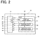
- the ECU 50 is equipped with a start-up control means 51, an opening/closing control means 52, and an operating state detection means 53.
- the start-up control means 51 starts up the engine 10 in accordance with a request from a driver to start up the engine 10. Assume, for example, that a signal requesting the start-up of the engine 10 is outputted by the driver turning on a starting switch 61 such as an ignition switch. In response to this signal, the start-up control means 51 actuates an electric motor (starter motor) 62 of the engine 10 by electric power supplied from the battery to start cranking, and also adjusts, as appropriate, an ignition timing by the spark plug 31, and the fuel injection amount from and the injection timing of the fuel injection valve 30, for example.
- starter motor electric motor
- the opening/closing control means 52 controls the opening/closing action of the waste gate valve 36 in accordance with the temperature of the engine 10 before completion of the start-up of the engine 10 by the start-up control means 51.
- the opening/closing control means 52 controls the opening/closing action of the waste gate valve 36.
- the waste gate valve 36 is brought into an open state.
- the waste gate valve 36 is brought into a closed state.
- the waste gate valve 36 is rendered open.
- the cranking speed can be increased to enhance the startability of the engine 10. That is, by bringing the waste gate valve 36 to an open state, the exhaust resistance of the exhaust gas passing through the turbocharger 32 is decreased.
- the cranking speed can be increased to enhance the startability of the engine 10.
- the actuator 36b of the waste gate valve 36 consumes electric power supplied from the battery during valve closing, as stated earlier.
- the battery for supplying electric power to the electric motor (starter motor) 62 for cranking of the engine, and the battery for supplying electric power for closing the actuator 36b of the waste gate valve 36 are common.
- the temperature Te is higher than the first set temperature Te1
- a smooth shift to the open/closed state of the waste gate valve 36 after completion of the start-up of the engine 10 to be described later can be expected. That is, the valve closing state is maintained before the start-up procedure for the engine 10 is started (while the exhaust gas is not flowing), whereby a wasteful closing action of the waste gate valve 36 after completion of start-up can be prevented.
- the timing for controlling the opening/closing action of the waste gate valve 36 is preferably prior to the start of the start-up procedure for the engine 10 by the start-up control means 51 as mentioned above, but before the start-up of the engine 10 is completed, may be after the start-up procedure for the engine 10 is started.
- the opening/closing control means 52 detects the temperature Te of the engine 10 again. If the temperature Te of the engine 10 is equal to or lower than a preset second set temperature Te2, the opening/closing control means 52 closes the waste gate valve 36. That is, if the waste gate valve 36 is open, it is closed. If it is closed, it is maintained in a closed state. If the temperature Te is higher than the second set temperature Te2, the opening/closing control means 52 opens the waste gate valve 36. That is, if the waste gate valve 36 is in a closed state, it is brought into an open state. If it is in an open state, its open state is maintained.
- the waste gate valve 36 When the temperature of the engine 10 is relatively low after completion of the start-up procedure for the engine 10, the waste gate valve 36 is put in a closed state. By so doing, the exhaust resistance rises to increase the inflow (back flow) of the exhaust gas from the combustion chamber 17 toward the intake pipe 20. As a result, fuel and intake air are heated with the heat of the exhaust gas. Thus, even in extremely cold starting, for example, a stable vehicle operation after start-up of the engine 10 can be achieved. Moreover, intense fluidity during the back flow promotes the mixing or atomization of fuel. These effects are marked, particularly, in a configuration having the fuel injection valve in the intake port.
- the exhaust pipe 27, the turbine 32a, the three-way catalyst 39, the O 2 sensor 40, and the linear air-fuel ratio sensor 41 are also in the extremely cold state. It is required, therefore, to heat them for activation to temperatures at which their purification performance is exhibited, or to temperatures at which the sensors work normally.
- the exhaust gas is stored inside the cylinder head 12 and warmed with the heat of the engine 10, whereby the exhaust gas can be brought to a high temperature early, the time until the three-way catalyst 39 and the linear air-fuel ratio sensor 41 become active is reduced, and the exhaust gas can be ameliorated early.
- the opening/closing control means 52 controls the open/closed state of the waste gate valve 36 after start-up of the engine 10 is completed. A determination of whether the start-up of the engine 10 is completed can be made, for example, based on an operating region (operating state) determined by the speed of and the load on the engine 10.
- the opening/closing control means 52 also controls the waste gate valve 36 in accordance with the temperature of the engine 10, and a method of detecting the temperature of the engine 10 is not restricted.
- the engine 10 is provided with a water temperature sensor (temperature detection means) 42 for detecting the temperature of cooling water. The results of detection by the water temperature sensor 42 may be adopted as the temperature of the engine 10, or the temperature of the engine 10 may be estimated from the results of detection by the water temperature sensor 42.
- the opening/closing control means 52 controls the opening/closing action of the intake bypass valve 38 along with the waste gate valve 36.
- the opening/closing control means 52 when rendering the waste gate valve 36 open, also brings the intake bypass valve 38 to an open state at the same time. If the temperature Te of the engine 10 before start of the start-up procedure is equal to or lower than the first set temperature Te1, the opening/closing control means 52 opens the waste gate valve 36 as mentioned above, and also opens the intake bypass valve 38. By so doing, the cranking speed can be increased further, and the startability of the engine 10 can be improved further.
- the waste gate valve 36 and the intake bypass valve 38 need not be controlled always simultaneously. It suffices, at least, to control the open/closed state of the waste gate valve 36 and, where necessary, to control the open/closed state of the intake bypass valve 38.
- the first set temperature Te1 and the second set temperature Te2 may be set, as appropriate, but in the present embodiment, the first set temperature Te1 is set at a lower value than the second set temperature Te2. This is because after completion of the start-up of the engine 10, combustion begins within the combustion chamber (cylinder) 17, so that the temperature (water temperature) Te of the engine 10 rises compared with the value before completion of the start-up.
- the first set temperature Te1 is set at a lower value than the second set temperature Te2 moreover, the period for maintaining the valve closed state is finely controlled, whereby power consumption necessary for maintaining the valve in the closed state can be cut down.
- the opening/closing control means 52 shifts from the above-described control in the cold state or the extremely cold state to normal control when the temperature Te of the engine 10 reaches a third set temperature Te3 after completion of the start-up of the engine 10.
- the third set temperature Te3 is a lower value than a warm-up completion temperature.
- the warm-up completion temperature refers to a temperature corresponding to the valve opening temperature of a thermostat (not shown). If the temperature Te of the engine 10 becomes equal to or higher than the third set temperature Te3, control in extremely cold starting or cold starting is switched to opening/closing control placing a high priority on fuel economy in an ordinary hot state, whereby optimal control for engine performance and fuel economy can be exercised at an early stage.
- the operating state detection means 53 detects the operating state of the engine 10, for example, based on information from various sensors such as a throttle position sensor 43 and a crank angle sensor 44.
- the operating region (operating state) of the engine 10 is specified by detecting the speed of and the load on the engine 10 based on information from the various sensors, and referring to predetermined maps. If, as a result, normal opening/closing control to be described later is executed, for example, the opening/closing control means 52 exercises appropriate control over the open/closed state of the waste gate valve 36 based on the detection results of the operating state detection means 53.
- Step S1 a request for start-up of the engine 10 is made by the operation of the starting switch 61 by a driver.
- the opening/closing control means 52 determines in Step S2 whether the temperature Te of the engine 10 is equal to or lower than the preset first set temperature Te1. If the temperature Te of the engine 10 is equal to or lower than the first set temperature Te1 (Step S2: Yes), the program proceeds to Step S3 in which the opening/closing control means 52 sets the waste gate valve 36 in an open state.
- Step S4 the opening/closing control means 52 sets the waste gate valve 36 in a closed state. For example, if the waste gate valve 36 is in an open state, the waste gate valve 36 is closed; if it is already in a closed state, this state is maintained.
- Step S5 the program goes to Step S5, in which the start-up control means 51 starts up the engine 10. That is, the start-up control means 51 actuates the electric motor (starter motor) 62 to start cranking.
- Step S6 the opening/closing control means 52 determines whether the temperature Te of the engine 10 is equal to or lower than the preset second set temperature Te2.
- Step S6 If, at this time, the temperature Te of the engine 10 is equal to or lower than the second set temperature Te2 (Step S6: Yes), the opening/closing control means 52 sets the waste gate valve 36 in a closed state (Step S7). That is, if the temperature of the engine 10 is relatively low, warm-up is granted priority and the waste gate valve 36 is closed (Step S7). Then, the opening/closing control means 52 further determines whether the temperature Te of the engine 10 is equal to or higher than the preset third set temperature Te3 (Step S8). The third set temperature Te3 is set at a temperature which is higher than the second set temperature Te2, but lower than the warm-up completion temperature as mentioned earlier.
- Step S8 If the temperature Te of the engine 10 is equal to or higher than the third set temperature Te3 (Step S8: Yes), the program proceeds to Step S9, in which the opening/control means 52 executes normal opening/closing control. That is, the open/closed state of the waste gate valve 36 is controlled, as appropriate, in accordance with the operating state of the engine 10.
- Step S6 the temperature Te of the engine 10 is higher than the second set temperature Te2 (Step S6: No), namely, if the engine 10 is warmed up to some degree, the program proceeds to Step S9 without controlling the waste gate valve 36 in accordance with the temperature of the engine 10, whereupon the opening/control means 52 exercises normal opening/closing control.
- the flow chart shown in Fig. 4 illustrates an example in which the open/closed state of the waste gate valve 36 is controlled after start of the start-up procedure for the engine 10.
- Step S11 a request for start-up of the engine 10 is made by the operation of the starting switch 61 by the driver.
- the start-up control means 51 actuates the starter motor 62 in Step S12 to start cranking. That is, the start-up procedure for the engine 10 is started.
- the opening/closing control means 52 determines whether the temperature Te of the engine 10 is equal to or lower than the first set temperature Te1.
- Step S14 the opening/closing control means 52 sets the waste gate valve 36 in an open state (Step S14). If the temperature Te of the engine 10 is higher than the first set temperature Te1 (Step S13: No), on the other hand, the opening/closing control means 52 sets the waste gate valve 36 in a closed state (Step S15). Then, the start-up of the engine 10 is completed in Step S16, whereafter the program goes to Step S17. In this step and subsequent steps, the open/closed state of the waste gate valve 36 is controlled, as appropriate, in accordance with the temperature of the engine 10. Since Steps S17 to S20 are the same as Steps S6 to S9 in the flow chart of Fig. 3 , their explanations are omitted here.
- the open/closed state of the waste gate valve 36 is controlled, as appropriate, in accordance with the temperature of the engine 10 at start-up. Consequently, even in extremely cold starting, for example, the engine 10 can be started up satisfactorily and, after start-up, stable operation of the engine can be achieved.
- the waste gate valve 36 is brought to a closed state.
- the direct injection type engine which injects fuel into the combustion chamber has been illustrated.
- the present invention can be applied to other types of engines, such as a manifold injection type engine which injects fuel into the intake pipe.
- a manifold injection type engine which injects fuel into the intake pipe.
- the present invention can be applied, for example, to an engine of a hybrid vehicle equipped with an electric motor.
Abstract
Description
- This invention relates to a control apparatus of an engine equipped with a waste gate valve for adjusting a boost pressure by a supercharger such as a turbocharger.
- Among conventional engines equipped with a supercharger, such as a turbocharger, have been those provided with an exhaust bypass passage for bypassing a turbine of the supercharger. In the exhaust bypass passage, a waste gate valve for opening and closing the exhaust bypass passage is provided. Upon opening/closing of the waste gate valve, an excessive rise in the boost pressure is suppressed to ensure stability of the boost pressure and inhibit damage to the engine or the supercharger itself.
- In recent years, it has been common practice to actively control the opening/closing action of the waste gate valve in accordance with the operating state of the engine. There has been, for example, a controller of the type which detects an ambient temperature and controls the opening of the waste gate valve in accordance with the detected ambient temperature, thereby preventing the occurrence of malfunction due to a change in the temperature of an intake system (see Patent Document 1).
- Patent Document 1:
JP-A-2012-97714 - Start-up of an engine (internal combustion engine) loaded on a vehicle, such as an automobile, is performed by cranking the engine, for example, in response to a start-up request by the operation of a starting switch such as an ignition switch. To enhance the startability of the engine, it is effective to increase the engine speed by cranking. For example, even under an environment where the startability of the engine is poor, as in extremely cold starting, the startability of the engine can be improved by increasing the engine speed by cranking. In accordance with an improvement in the startability, moreover, an engine body, a catalyst, and an air-fuel ratio sensor can be warmed up early, and a stable operation after starting and exhaust gas amelioration can also be realized.
- With the conventional engine equipped with a supercharger, however, even when it is attempted to increase the engine speed by cranking, the turbine of the supercharger offers a resistance, making it impossible to increase the engine speed sufficiently.
- The present invention has been accomplished in the light of the above circumstances. It is an object of the invention to provide a control apparatus of an engine which, for example, can enhance the startability of the engine even in extremely cold starting, can also achieve a stable operation after starting, and can further ameliorate an exhaust gas at an early stage.
- A first aspect of the present invention, for solving the above problems, is a control apparatus of an engine having an exhaust bypass passage for bypassing a turbine of a supercharger, and a waste gate valve for opening and closing the exhaust bypass passage, the control apparatus comprising: an opening/closing control means for controlling the opening/closing action of the waste gate valve; and a start-up control means for starting up the engine in accordance with an engine start-up request, wherein the opening/closing control means controls the opening/closing action of the waste gate valve in accordance with the temperature of the engine before a start-up procedure for the engine by the start-up control means is started and, if the temperature of the engine is equal to or lower than a first set temperature, controls the waste gate valve in a valve opening direction.
- A second aspect of the present invention is the control apparatus of an engine according to the first aspect, wherein the opening/closing control means controls the opening/closing action of the waste gate valve in accordance with the temperature of the engine after the start-up procedure for the engine is completed and, if the temperature of the engine is equal to or lower than a second set temperature, controls the waste gate valve in a valve closing direction.
- A third aspect of the present invention is the control apparatus of an engine according to the second aspect, wherein the first set temperature is set to be lower than the second set temperature.
- A fourth aspect of the present invention is the control apparatus of an engine according to the third aspect, wherein if the temperature of the engine is equal to or lower than the second set temperature after the start-up procedure for the engine is completed, the opening/closing control means maintains the waste gate valve in a closed state until the temperature of the engine becomes equal to or higher than a third set temperature which is higher than the second set temperature, but lower than the warm-up completion temperature of the engine.
- A fifth aspect of the present invention is the control apparatus of an engine according to any one of the first to fourth aspects, wherein the engine has an intake bypass valve for opening and closing an intake bypass passage for bypassing a compressor of the supercharger, and the opening/closing control means controls the opening/closing action of the intake bypass valve as well as the opening/closing action of the waste gate valve and, in controlling the waste gate valve in the valve opening direction, also controls the intake bypass valve in a valve opening direction.
- A sixth aspect of the present invention is the control apparatus of an engine according to any one of the first to fifth aspects, wherein the waste gate valve has an actuator which works for valve closing by use of electric power supplied from a battery, and works for valve opening upon a cutoff of the electric power supplied from the battery, and the start-up control means actuates an electric motor for cranking the engine by use of the electric power supplied from the battery.
- With the present invention mentioned above, even in extremely cold starting, for example, stable operation of the engine after start-up can be achieved. Moreover, the engine speed by cranking can be increased. Thus, the engine can be started satisfactorily.
-
- [
Fig. 1 ] is a schematic view of an engine equipped with a control apparatus according to an embodiment of the present invention. - [
Fig. 2 ] is a block diagram showing the schematic configuration of the control apparatus according to the embodiment of the present invention. - [
Fig. 3 ] is a flow chart showing an example of opening/closing control over a waste gate valve according to the embodiment of the present invention. - [
Fig. 4 ] is a flow chart showing another example of opening/closing control over the waste gate valve according to the embodiment of the present invention. - An embodiment of the present invention will now be described in detail by reference to the accompanying drawings.
- First of all, an explanation will be offered for the entire configuration of an
engine 10 according to the embodiment of the present invention. As shown inFig. 1 , anengine body 11 constituting theengine 10 has acylinder head 12 and acylinder block 13, and a piston 14 is accommodated within thecylinder block 13. The piston 14 is connected to acrankshaft 16 via a connectingrod 15. The piston 14, thecylinder head 12, and thecylinder block 13 form a combustion chamber 17. - An
intake port 18 is formed in thecylinder head 12, and an intake pipe (intake passage) 20 including anintake manifold 19 is connected to theintake port 18. Theintake pipe 20 is provided with an intake pressure sensor (MAP sensor) 21 for detecting an intake pressure, and anintake temperature sensor 22 for detecting the temperature of intake air. Anintake valve 23 is also provided inside theintake port 18, and theintake port 18 is opened and closed with theintake valve 23. That is, theintake valve 23 is adapted to act following anintake cam 24a of anintake camshaft 24 rotating in accordance with an engine revolution, thereby allowing the combustion chamber 17 and theintake port 18 to communicate with each other and to be cut off from each other. Further, anexhaust port 25 is formed in thecylinder head 12, and an exhaust pipe (exhaust passage) 27 including anexhaust manifold 26 is connected to the interior of theexhaust port 25. Anexhaust valve 28 is provided in theexhaust port 25 and, as does theintake valve 23 in theintake port 18, theexhaust valve 28 is adapted to act following anexhaust cam 29a of anexhaust camshaft 29, thereby allowing the combustion chamber 17 and theexhaust port 25 to communicate with each other and to be cut off from each other. In the present embodiment, theexhaust port 25 and theexhaust manifold 26 are constituted inside thecylinder head 12. Theexhaust manifold 26 is equipped with an exhaust collecting section (not shown), and the exhaust collecting section is connected to aturbine 32a of a turbocharger 32 (to be described later) via an exhaust flange of thecylinder head 12. - Moreover, the
engine body 11 is provided with afuel injection valve 30 for injecting fuel into the combustion chamber 17 of each cylinder. Thefuel injection valve 30 is supplied with fuel from high pressure fuel delivery piping, although this is not shown. The high pressure fuel delivery piping is supplied with fuel, which has been supplied from a low pressure fuel pump within a fuel tank, while being pressurized to a predetermined pressure by a high pressure fuel pump. Thecylinder head 12 is further mounted with aspark plug 31 for each cylinder. - The
turbocharger 32, a supercharger, is provided halfway between theintake pipe 20 and theexhaust pipe 27. Theturbocharger 32 has theturbine 32a and acompressor 32b, and theturbine 32a and thecompressor 32b are coupled together by aturbine shaft 32c. When an exhaust gas flows into theturbocharger 32, theturbine 32a is rotated by the flow of the exhaust gas and, in accordance with the rotation of theturbine 32a, thecompressor 32b is rotated. Air (intake air) pressurized by the rotation of thecompressor 32b is sent out into theintake pipe 20, and supplied to eachintake port 18. - An
intercooler 33 is provided at a portion of theintake pipe 20 downstream of theturbocharger 32, and athrottle valve 34 is provided downstream of theintercooler 33. An upstream side and a downstream side of theexhaust pipe 27, with theturbocharger 32 being interposed therebetween, are connected together by anexhaust bypass passage 35. That is, theexhaust bypass passage 35 is a passage for bypassing theturbine 32a of theturbocharger 32. A waste gate valve (WGV) 36 is provided in theexhaust bypass passage 35. The waste gate valve (WGV) 36 is equipped with avalve body 36a, and an electrically operatedactuator 36b for driving thevalve body 36a, and the amount of the exhaust gas flowing through theexhaust bypass passage 35 can be adjusted depending on the opening of thevalve body 36a. That is, thewaste gate valve 36 is configured to be capable of adjusting the boost pressure of theturbocharger 32 by adjustment of its opening. - The structure of the
waste gate valve 36 may rely on conventional technologies, and may be a structure for maintaining a valve closing state by a spring or the like, for example, as described inJP-A-2006-274831 electric actuator 36b (seeJP-A-2012-62803 actuator 36b. - An upstream side and a downstream side of the
intake pipe 20, with theturbocharger 32 being interposed therebetween, are connected together by anintake bypass passage 37. That is, theintake bypass passage 37 is a passage for bypassing thecompressor 32b of theturbocharger 32. In theintake bypass passage 37, anintake bypass valve 38 is provided for opening and closing theintake bypass passage 37. The configuration of theintake bypass valve 38 is not limited, but in the present embodiment, is a configuration equipped with a valve body and an actuator, as is that of thewaste gate valve 36. - A three-
way catalyst 39, an exhaust gas purification catalyst, is interposed in a portion of theexhaust pipe 27 on the downstream side of theturbocharger 32. An O2 sensor 40 for detecting the O2 concentration of the exhaust gas after passage through the catalyst is provided on the outlet side of the three-way catalyst 39. A linear air-fuel ratio sensor (LAFS) 41 for detecting the air-fuel ratio of the exhaust gas (exhaust air-fuel ratio) before passage through the catalyst is provided on the inlet side of the three-way catalyst 39. - The
engine 10 is also equipped with an electronic control unit (ECU) 50, and theECU 50 is equipped with input/output devices, storage devices for storage of control programs and control maps, a central processing unit, and timers and counters. TheECU 50 exercises the integrated control of theengine 10 based on information from various sensors. The control apparatus of an engine according to the present embodiment is composed of such anECU 50 and, as will be described below, controls the opening/closing action (opening degree or position) of thewaste gate valve 36 in accordance with the operating state of the engine 10 (engine body 11). - The control apparatus of an engine according to the present invention is characterized by control over the opening/closing action of the
waste gate valve 36 in cold starting of theengine 10. As shown inFig. 2 , theECU 50 is equipped with a start-up control means 51, an opening/closing control means 52, and an operating state detection means 53. - The start-up control means 51 starts up the
engine 10 in accordance with a request from a driver to start up theengine 10. Assume, for example, that a signal requesting the start-up of theengine 10 is outputted by the driver turning on a startingswitch 61 such as an ignition switch. In response to this signal, the start-up control means 51 actuates an electric motor (starter motor) 62 of theengine 10 by electric power supplied from the battery to start cranking, and also adjusts, as appropriate, an ignition timing by thespark plug 31, and the fuel injection amount from and the injection timing of thefuel injection valve 30, for example. - At the request of the driver for start-up of the
engine 10, the opening/closing control means 52 controls the opening/closing action of thewaste gate valve 36 in accordance with the temperature of theengine 10 before completion of the start-up of theengine 10 by the start-up control means 51. In the present embodiment, before the start-up procedure for theengine 10 by the start-up control means 51 is started, the opening/closing control means 52 controls the opening/closing action of thewaste gate valve 36. - Concretely, if the temperature Te of the
engine 10 is equal to or lower than a preset first set temperature Te1, thewaste gate valve 36 is brought into an open state. In the present embodiment, if the temperature Te of theengine 10 is higher than the first set temperature Te1, thewaste gate valve 36 is brought into a closed state. - As noted above, in a relatively cold starting state, where the temperature Te of the
engine 10 is equal to or lower than the first set temperature Te1, or in an extremely cold starting state, thewaste gate valve 36 is rendered open. By so doing, the cranking speed can be increased to enhance the startability of theengine 10. That is, by bringing thewaste gate valve 36 to an open state, the exhaust resistance of the exhaust gas passing through theturbocharger 32 is decreased. Thus, the cranking speed can be increased to enhance the startability of theengine 10. - Furthermore, the occurrence of such a trouble that the complete explosion of the
engine 10 is impossible at the start-up of theengine 10 can be inhibited. Concretely, theactuator 36b of thewaste gate valve 36 consumes electric power supplied from the battery during valve closing, as stated earlier. The battery for supplying electric power to the electric motor (starter motor) 62 for cranking of the engine, and the battery for supplying electric power for closing theactuator 36b of thewaste gate valve 36 are common. Thus, when thewaste gate valve 36 is maintained in a closed state at the start-up of theengine 10, electric power to be supplied for cranking is consumed to reduce the cranking speed, so that theengine 10 may fail to explode completely. When thewaste gate valve 36 is placed in an open state at the start-up of theengine 10, by contrast, there is no power consumption by theactuator 36b, and sufficient power can be supplied for cranking. Hence, the occurrence of a trouble, such as incomplete explosion of theengine 10, can be suppressed. - If the temperature Te is higher than the first set temperature Te1, on the other hand, a smooth shift to the open/closed state of the
waste gate valve 36 after completion of the start-up of theengine 10 to be described later can be expected. That is, the valve closing state is maintained before the start-up procedure for theengine 10 is started (while the exhaust gas is not flowing), whereby a wasteful closing action of thewaste gate valve 36 after completion of start-up can be prevented. - The timing for controlling the opening/closing action of the
waste gate valve 36 is preferably prior to the start of the start-up procedure for theengine 10 by the start-up control means 51 as mentioned above, but before the start-up of theengine 10 is completed, may be after the start-up procedure for theengine 10 is started. - After completion of the start-up procedure for the
engine 10, the opening/closing control means 52 detects the temperature Te of theengine 10 again. If the temperature Te of theengine 10 is equal to or lower than a preset second set temperature Te2, the opening/closing control means 52 closes thewaste gate valve 36. That is, if thewaste gate valve 36 is open, it is closed. If it is closed, it is maintained in a closed state. If the temperature Te is higher than the second set temperature Te2, the opening/closing control means 52 opens thewaste gate valve 36. That is, if thewaste gate valve 36 is in a closed state, it is brought into an open state. If it is in an open state, its open state is maintained. - When the temperature of the
engine 10 is relatively low after completion of the start-up procedure for theengine 10, thewaste gate valve 36 is put in a closed state. By so doing, the exhaust resistance rises to increase the inflow (back flow) of the exhaust gas from the combustion chamber 17 toward theintake pipe 20. As a result, fuel and intake air are heated with the heat of the exhaust gas. Thus, even in extremely cold starting, for example, a stable vehicle operation after start-up of theengine 10 can be achieved. Moreover, intense fluidity during the back flow promotes the mixing or atomization of fuel. These effects are marked, particularly, in a configuration having the fuel injection valve in the intake port. Since the exhaust gas at a high temperature remains within the exhaust port, moreover, the warm-up of theengine 10 can be promoted, a rise in the heater water temperature can be induced, and heating performance can also be enhanced. Such effects are marked particularly in a structure having the exhaust manifold and the cylinder head integrated. - In an extremely cold state, the
exhaust pipe 27, theturbine 32a, the three-way catalyst 39, the O2 sensor 40, and the linear air-fuel ratio sensor 41 are also in the extremely cold state. It is required, therefore, to heat them for activation to temperatures at which their purification performance is exhibited, or to temperatures at which the sensors work normally. In the extremely cold state, as described above, the exhaust gas is stored inside thecylinder head 12 and warmed with the heat of theengine 10, whereby the exhaust gas can be brought to a high temperature early, the time until the three-way catalyst 39 and the linear air-fuel ratio sensor 41 become active is reduced, and the exhaust gas can be ameliorated early. - The opening/closing control means 52 controls the open/closed state of the
waste gate valve 36 after start-up of theengine 10 is completed. A determination of whether the start-up of theengine 10 is completed can be made, for example, based on an operating region (operating state) determined by the speed of and the load on theengine 10. The opening/closing control means 52 also controls thewaste gate valve 36 in accordance with the temperature of theengine 10, and a method of detecting the temperature of theengine 10 is not restricted. For example, theengine 10 is provided with a water temperature sensor (temperature detection means) 42 for detecting the temperature of cooling water. The results of detection by thewater temperature sensor 42 may be adopted as the temperature of theengine 10, or the temperature of theengine 10 may be estimated from the results of detection by thewater temperature sensor 42. - Furthermore, the opening/closing control means 52 controls the opening/closing action of the
intake bypass valve 38 along with thewaste gate valve 36. In the present embodiment, the opening/closing control means 52, when rendering thewaste gate valve 36 open, also brings theintake bypass valve 38 to an open state at the same time. If the temperature Te of theengine 10 before start of the start-up procedure is equal to or lower than the first set temperature Te1, the opening/closing control means 52 opens thewaste gate valve 36 as mentioned above, and also opens theintake bypass valve 38. By so doing, the cranking speed can be increased further, and the startability of theengine 10 can be improved further. - The
waste gate valve 36 and theintake bypass valve 38 need not be controlled always simultaneously. It suffices, at least, to control the open/closed state of thewaste gate valve 36 and, where necessary, to control the open/closed state of theintake bypass valve 38. - The first set temperature Te1 and the second set temperature Te2 may be set, as appropriate, but in the present embodiment, the first set temperature Te1 is set at a lower value than the second set temperature Te2. This is because after completion of the start-up of the
engine 10, combustion begins within the combustion chamber (cylinder) 17, so that the temperature (water temperature) Te of theengine 10 rises compared with the value before completion of the start-up. By setting the first set temperature Te1 at a lower value than the second set temperature Te2, moreover, the period for maintaining the valve closed state is finely controlled, whereby power consumption necessary for maintaining the valve in the closed state can be cut down. - The opening/closing control means 52 shifts from the above-described control in the cold state or the extremely cold state to normal control when the temperature Te of the
engine 10 reaches a third set temperature Te3 after completion of the start-up of theengine 10. The third set temperature Te3 is a lower value than a warm-up completion temperature. The warm-up completion temperature refers to a temperature corresponding to the valve opening temperature of a thermostat (not shown). If the temperature Te of theengine 10 becomes equal to or higher than the third set temperature Te3, control in extremely cold starting or cold starting is switched to opening/closing control placing a high priority on fuel economy in an ordinary hot state, whereby optimal control for engine performance and fuel economy can be exercised at an early stage. - The operating state detection means 53 detects the operating state of the
engine 10, for example, based on information from various sensors such as athrottle position sensor 43 and acrank angle sensor 44. For example, the operating region (operating state) of theengine 10 is specified by detecting the speed of and the load on theengine 10 based on information from the various sensors, and referring to predetermined maps. If, as a result, normal opening/closing control to be described later is executed, for example, the opening/closing control means 52 exercises appropriate control over the open/closed state of thewaste gate valve 36 based on the detection results of the operating state detection means 53. - Next, examples of control over the opening/closing action of the waste gate valve in engine start-up will be described by reference to flow charts in
Figs. 3 and4 . - The flow chart shown in
Fig. 3 illustrates an example in which the open/closed state of thewaste gate valve 36 is controlled before start of the start-up procedure for theengine 10. In Step S1, a request for start-up of theengine 10 is made by the operation of the startingswitch 61 by a driver. In response, the opening/closing control means 52 determines in Step S2 whether the temperature Te of theengine 10 is equal to or lower than the preset first set temperature Te1. If the temperature Te of theengine 10 is equal to or lower than the first set temperature Te1 (Step S2: Yes), the program proceeds to Step S3 in which the opening/closing control means 52 sets thewaste gate valve 36 in an open state. For example, if thewaste gate valve 36 is in a closed state, thewaste gate valve 36 is opened; if it is already in an open state, this state is maintained. If the temperature Te of theengine 10 is higher than the first set temperature Te1 (Step S2: No), on the other hand, the opening/closing control means 52 sets thewaste gate valve 36 in a closed state (Step S4). For example, if thewaste gate valve 36 is in an open state, thewaste gate valve 36 is closed; if it is already in a closed state, this state is maintained. - Then, the program goes to Step S5, in which the start-up control means 51 starts up the
engine 10. That is, the start-up control means 51 actuates the electric motor (starter motor) 62 to start cranking. After the start-up procedure for theengine 10 is completed, the program proceeds to Step S6. In Step S6, the opening/closing control means 52 determines whether the temperature Te of theengine 10 is equal to or lower than the preset second set temperature Te2. - If, at this time, the temperature Te of the
engine 10 is equal to or lower than the second set temperature Te2 (Step S6: Yes), the opening/closing control means 52 sets thewaste gate valve 36 in a closed state (Step S7). That is, if the temperature of theengine 10 is relatively low, warm-up is granted priority and thewaste gate valve 36 is closed (Step S7). Then, the opening/closing control means 52 further determines whether the temperature Te of theengine 10 is equal to or higher than the preset third set temperature Te3 (Step S8). The third set temperature Te3 is set at a temperature which is higher than the second set temperature Te2, but lower than the warm-up completion temperature as mentioned earlier. If the temperature Te of theengine 10 is equal to or higher than the third set temperature Te3 (Step S8: Yes), the program proceeds to Step S9, in which the opening/control means 52 executes normal opening/closing control. That is, the open/closed state of thewaste gate valve 36 is controlled, as appropriate, in accordance with the operating state of theengine 10. - If, in Step S6, the temperature Te of the
engine 10 is higher than the second set temperature Te2 (Step S6: No), namely, if theengine 10 is warmed up to some degree, the program proceeds to Step S9 without controlling thewaste gate valve 36 in accordance with the temperature of theengine 10, whereupon the opening/control means 52 exercises normal opening/closing control. - The flow chart shown in
Fig. 4 illustrates an example in which the open/closed state of thewaste gate valve 36 is controlled after start of the start-up procedure for theengine 10. In Step S11, a request for start-up of theengine 10 is made by the operation of the startingswitch 61 by the driver. In response, the start-up control means 51 actuates thestarter motor 62 in Step S12 to start cranking. That is, the start-up procedure for theengine 10 is started. Then, in Step S13, the opening/closing control means 52 determines whether the temperature Te of theengine 10 is equal to or lower than the first set temperature Te1. If, at this time, the temperature Te of theengine 10 is equal to or lower than the first set temperature Te1 (Step S13: Yes), the program proceeds to Step S14, in which the opening/closing control means 52 sets thewaste gate valve 36 in an open state (Step S14). If the temperature Te of theengine 10 is higher than the first set temperature Te1 (Step S13: No), on the other hand, the opening/closing control means 52 sets thewaste gate valve 36 in a closed state (Step S15). Then, the start-up of theengine 10 is completed in Step S16, whereafter the program goes to Step S17. In this step and subsequent steps, the open/closed state of thewaste gate valve 36 is controlled, as appropriate, in accordance with the temperature of theengine 10. Since Steps S17 to S20 are the same as Steps S6 to S9 in the flow chart ofFig. 3 , their explanations are omitted here. - With the control apparatus of an engine according to the present embodiment, as described above, the open/closed state of the
waste gate valve 36 is controlled, as appropriate, in accordance with the temperature of theengine 10 at start-up. Consequently, even in extremely cold starting, for example, theengine 10 can be started up satisfactorily and, after start-up, stable operation of the engine can be achieved. - Although the embodiment of the present invention has been described above, it is to be noted, needless to say, that the present invention is in no way limited to the foregoing embodiment.
- In the above embodiment, for example, after completion of the start-up of the
engine 10, it is determined whether the temperature Te of theengine 10 is equal to or lower than the second set temperature Te2. When the temperature Te is higher than the second set temperature Te2, normal opening/closing control is performed. It is permissible, however, to provide a period of time during which thewaste gate valve 36 is in an open state, before normal opening/closing control is carried out. - In the above embodiment, moreover, after completion of the start-up of the
engine 10, it is determined whether the temperature Te of theengine 10 is equal to or lower than the second set temperature Te2. When the temperature Te is equal to or lower than the second set temperature Te2, thewaste gate valve 36 is brought to a closed state. However, it is permissible, for example, to set thewaste gate valve 36 once in a closed state, without making a determination as to the temperature of theengine 10, upon completion of the start-up of theengine 10; and to switch to normal opening/closing control at a time when the temperature Te of theengine 10 becomes equal to or higher than a predetermined temperature (third set temperature Te3). - In the above embodiment, moreover, the direct injection type engine which injects fuel into the combustion chamber (into the cylinder) has been illustrated. However, the present invention can be applied to other types of engines, such as a manifold injection type engine which injects fuel into the intake pipe. Besides, only the configuration of the engine has been illustrated in the embodiment, but it goes without saying that the present invention can be applied, for example, to an engine of a hybrid vehicle equipped with an electric motor.
-
- 10
- Engine
- 11
- Engine body
- 12
- Cylinder head
- 13
- Cylinder block
- 14
- Piston
- 15
- Connecting rod
- 16
- Crankshaft
- 17
- Combustion chamber
- 18
- Intake port
- 19
- Intake manifold
- 20
- Intake pipe
- 21
- Intake pressure sensor
- 22
- Intake temperature sensor
- 23
- Intake valve
- 24
- Intake camshaft
- 24a
- Intake cam
- 25
- Exhaust port
- 26
- Exhaust manifold
- 27
- Exhaust pipe
- 28
- Exhaust valve
- 29
- Exhaust camshaft
- 29a
- Exhaust cam
- 30
- Fuel injection valve
- 31
- Spark plug
- 32
- Turbocharger
- 32a
- Turbine
- 32b
- Compressor
- 32c
- Turbine shaft
- 33
- Intercooler
- 34
- Throttle valve
- 35
- Exhaust bypass passage
- 36
- Waste gate valve
- 37
- Intake bypass passage
- 38
- Intake bypass valve
- 39
- Three-way catalyst
- 40
- O2 sensor
- 41
- Linear air-fuel ratio sensor
- 42
- Water temperature sensor
- 43
- Throttle position sensor
- 44
- Crank angle sensor
- 61
- Starting switch
- 62
- Electric motor (starter motor)
Claims (6)
- A control apparatus of an engine having
an exhaust bypass passage for bypassing a turbine of a supercharger, and
a waste gate valve for opening and closing the exhaust bypass passage,
the control apparatus comprising:opening/closing control means for controlling an opening/closing action of the waste gate valve; andstart-up control means for starting up the engine in accordance with an engine start-up request,wherein the opening/closing control meanscontrols the opening/closing action of the waste gate valve in accordance with a temperature of the engine before a start-up procedure for the engine by the start-up control means is started, andif the temperature of the engine is equal to or lower than a first set temperature, controls the waste gate valve in a valve opening direction. - The control apparatus of an engine according to claim 1, wherein
the opening/closing control means
controls the opening/closing action of the waste gate valve in accordance with the temperature of the engine after the start-up procedure for the engine is completed, and
if the temperature of the engine is equal to or lower than a second set temperature, controls the waste gate valve in a valve closing direction. - The control apparatus of an engine according to claim 2, wherein
the first set temperature is set to be lower than the second set temperature. - The control apparatus of an engine according to claim 3, wherein
if the temperature of the engine is equal to or lower than the second set temperature after the start-up procedure for the engine is completed,
the opening/closing control means maintains the waste gate valve in a closed state until the temperature of the engine becomes equal to or higher than a third set temperature which is higher than the second set temperature, but lower than a warm-up completion temperature of the engine. - The control apparatus of an engine according to any one of claims 1 to 4, wherein
the engine has an intake bypass valve for opening and closing an intake bypass passage for bypassing a compressor of the supercharger, and
the opening/closing control means controls an opening/closing action of the intake bypass valve as well as the opening/closing action of the waste gate valve and, in controlling the waste gate valve in the valve opening direction, also controls the intake bypass valve in a valve opening direction. - The control apparatus of an engine according to any one of claims 1 to 5, wherein
the waste gate valve has an actuator which works for valve closing by use of electric power supplied from a battery, and works for valve opening upon a cutoff of the electric power supplied from the battery, and
the start-up control means actuates an electric motor for cranking the engine by use of the electric power supplied from the battery.
Applications Claiming Priority (2)
| Application Number | Priority Date | Filing Date | Title |
|---|---|---|---|
| JP2013126071A JP6112299B2 (en) | 2013-06-14 | 2013-06-14 | Engine control device |
| PCT/JP2014/065706 WO2014200085A1 (en) | 2013-06-14 | 2014-06-13 | Engine control device |
Publications (3)
| Publication Number | Publication Date |
|---|---|
| EP3009631A1 true EP3009631A1 (en) | 2016-04-20 |
| EP3009631A4 EP3009631A4 (en) | 2017-03-08 |
| EP3009631B1 EP3009631B1 (en) | 2018-05-09 |
Family
ID=52022371
Family Applications (1)
| Application Number | Title | Priority Date | Filing Date |
|---|---|---|---|
| EP14811126.3A Active EP3009631B1 (en) | 2013-06-14 | 2014-06-13 | Engine control device |
Country Status (5)
| Country | Link |
|---|---|
| US (1) | US9896994B2 (en) |
| EP (1) | EP3009631B1 (en) |
| JP (1) | JP6112299B2 (en) |
| CN (1) | CN105308290B (en) |
| WO (1) | WO2014200085A1 (en) |
Cited By (3)
| Publication number | Priority date | Publication date | Assignee | Title |
|---|---|---|---|---|
| WO2016192914A1 (en) * | 2015-06-01 | 2016-12-08 | Volkswagen Aktiengesellschaft | Method and control device for operating a drive device |
| WO2018185160A1 (en) * | 2017-04-04 | 2018-10-11 | Liebherr-Components Colmar Sas | Internal combustion engine and generator for electrical power supply |
| EP3289199B1 (en) * | 2015-04-27 | 2019-11-27 | Innio Jenbacher GmbH & Co OG | Internal combustion engine and method for starting an internal combustion engine |
Families Citing this family (2)
| Publication number | Priority date | Publication date | Assignee | Title |
|---|---|---|---|---|
| US11131258B2 (en) * | 2020-02-21 | 2021-09-28 | Ford Global Technologies, Llc | Methods and system for reducing engine hydrocarbon emissions |
| CN112228189B (en) * | 2020-10-12 | 2021-12-21 | 潍柴动力股份有限公司 | Exhaust gas heat management coupling method and exhaust gas treatment system |
Family Cites Families (41)
| Publication number | Priority date | Publication date | Assignee | Title |
|---|---|---|---|---|
| JPS5620717A (en) * | 1979-07-30 | 1981-02-26 | Nissan Motor Co Ltd | Knocking controller for turbo-charger |
| US4404804A (en) * | 1980-01-10 | 1983-09-20 | Toyo Kogyo Co., Ltd. | Internal combustion engine having a turbo-supercharger and a catalytic exhaust gas purifying device |
| JPS6057748U (en) * | 1983-09-28 | 1985-04-22 | 日産自動車株式会社 | Turbo charger protection device |
| JPS60127428U (en) * | 1984-02-03 | 1985-08-27 | 日産自動車株式会社 | Turbo charger protection device |
| JPS61197721A (en) * | 1985-02-26 | 1986-09-02 | Fuji Heavy Ind Ltd | Supercharging pressure control system |
| JPS61275525A (en) * | 1985-05-29 | 1986-12-05 | Nissan Motor Co Ltd | Supercharged pressure control device for turbocharger |
| JPS62174536A (en) * | 1986-01-27 | 1987-07-31 | Mazda Motor Corp | Engine equipped with pressure wave supercharger |
| JPH0513964Y2 (en) * | 1986-06-12 | 1993-04-14 | ||
| JPH0259230U (en) * | 1988-10-24 | 1990-04-27 | ||
| JPH04301137A (en) * | 1991-03-28 | 1992-10-23 | Toyota Motor Corp | Engine fitted with mechanical supercharger |
| JPH09109665A (en) * | 1995-10-23 | 1997-04-28 | Teikoku Piston Ring Co Ltd | On-vehicle refrigerating device |
| JP3090055B2 (en) | 1996-08-06 | 2000-09-18 | トヨタ自動車株式会社 | Variable nozzle turbocharger |
| JP3789804B2 (en) * | 2001-10-30 | 2006-06-28 | 本田技研工業株式会社 | Ignition control device for turbocharged engine |
| JP2006274831A (en) | 2005-03-28 | 2006-10-12 | Denso Corp | Control device for internal combustion engine with turbocharger |
| JP4395099B2 (en) * | 2005-05-20 | 2010-01-06 | トヨタ自動車株式会社 | Control device for an internal combustion engine with a supercharger |
| US8375714B2 (en) * | 2005-06-27 | 2013-02-19 | General Electric Company | System and method for operating a turbocharged engine |
| JP2007100607A (en) * | 2005-10-05 | 2007-04-19 | Toyota Motor Corp | Starting control device of internal combustion engine |
| JP2007285222A (en) * | 2006-04-18 | 2007-11-01 | Toyota Motor Corp | Exhaust control device for internal combustion engine |
| JP2008095542A (en) * | 2006-10-06 | 2008-04-24 | Toyota Motor Corp | Control system of internal combustion engine |
| JP2008180176A (en) * | 2007-01-25 | 2008-08-07 | Toyota Motor Corp | Exhaust system for multiple cylinder internal combustion engine |
| US8001778B2 (en) * | 2007-09-25 | 2011-08-23 | Ford Global Technologies, Llc | Turbocharged engine control operation with adjustable compressor bypass |
| US8001782B2 (en) * | 2007-09-26 | 2011-08-23 | Ford Global Technologies, Llc | Approach for identifying and responding to an unresponsive wastegate in a twin turbocharged engine |
| US7921944B2 (en) * | 2007-10-29 | 2011-04-12 | Ford Global Technologies, Llc | Compression system for internal combustion engine including a rotationally uncoupled exhaust gas turbine |
| JP4877200B2 (en) * | 2007-11-06 | 2012-02-15 | トヨタ自動車株式会社 | Control device for internal combustion engine |
| JP5035285B2 (en) * | 2009-03-26 | 2012-09-26 | トヨタ自動車株式会社 | Control device for an internal combustion engine with a supercharger |
| US8397499B2 (en) * | 2009-08-24 | 2013-03-19 | Ford Global Technologies, Llc | Methods and systems for turbocharger control |
| US8468821B2 (en) * | 2009-11-19 | 2013-06-25 | GM Global Technology Operations LLC | Dual-loop control systems and methods for a sequential turbocharger |
| JP4952849B2 (en) * | 2010-02-24 | 2012-06-13 | トヨタ自動車株式会社 | Control device for internal combustion engine |
| JP5348338B2 (en) * | 2010-06-30 | 2013-11-20 | マツダ株式会社 | Engine control device |
| JP5299390B2 (en) | 2010-09-15 | 2013-09-25 | 株式会社デンソー | Turbocharger |
| JP2012097714A (en) | 2010-11-05 | 2012-05-24 | Toyota Motor Corp | Control device for internal combustion engine with supercharger |
| JP2012219634A (en) * | 2011-04-04 | 2012-11-12 | Toyota Motor Corp | Control device for internal combustion engine with egr device |
| EP2696053B1 (en) * | 2011-04-08 | 2018-01-17 | Toyota Jidosha Kabushiki Kaisha | Control device for an internal combustion engine with supercharger |
| US8301358B2 (en) * | 2011-06-21 | 2012-10-30 | Ford Global Technologies, Llc | Method of engine starting |
| DE102011078282A1 (en) * | 2011-06-29 | 2013-01-03 | Ford Global Technologies, Llc | Method for controlling a turbocharger arrangement of an internal combustion engine and control device |
| US8978378B2 (en) * | 2011-10-20 | 2015-03-17 | Ford Global Technologies, Llc | Method and system for reducing turbocharger noise during cold start |
| US9890718B2 (en) * | 2012-01-11 | 2018-02-13 | Toyota Jidosha Kabushiki Kaisha | Control apparatus for internal combustion engine |
| US9416724B2 (en) * | 2012-08-08 | 2016-08-16 | Ford Global Technologies, Llc | Multi-staged wastegate |
| US9010114B2 (en) * | 2013-02-19 | 2015-04-21 | The Boeing Company | Air charge system and method for an internal combustion engine |
| JP6137473B2 (en) * | 2013-06-27 | 2017-05-31 | 三菱自動車工業株式会社 | Engine control device |
| JP2015129457A (en) * | 2014-01-07 | 2015-07-16 | トヨタ自動車株式会社 | Internal combustion engine controller |
-
2013
- 2013-06-14 JP JP2013126071A patent/JP6112299B2/en active Active
-
2014
- 2014-06-13 WO PCT/JP2014/065706 patent/WO2014200085A1/en active Application Filing
- 2014-06-13 CN CN201480033808.8A patent/CN105308290B/en active Active
- 2014-06-13 EP EP14811126.3A patent/EP3009631B1/en active Active
-
2015
- 2015-12-10 US US14/965,366 patent/US9896994B2/en active Active
Non-Patent Citations (1)
| Title |
|---|
| See references of WO2014200085A1 * |
Cited By (3)
| Publication number | Priority date | Publication date | Assignee | Title |
|---|---|---|---|---|
| EP3289199B1 (en) * | 2015-04-27 | 2019-11-27 | Innio Jenbacher GmbH & Co OG | Internal combustion engine and method for starting an internal combustion engine |
| WO2016192914A1 (en) * | 2015-06-01 | 2016-12-08 | Volkswagen Aktiengesellschaft | Method and control device for operating a drive device |
| WO2018185160A1 (en) * | 2017-04-04 | 2018-10-11 | Liebherr-Components Colmar Sas | Internal combustion engine and generator for electrical power supply |
Also Published As
| Publication number | Publication date |
|---|---|
| US9896994B2 (en) | 2018-02-20 |
| CN105308290B (en) | 2018-01-02 |
| EP3009631A4 (en) | 2017-03-08 |
| CN105308290A (en) | 2016-02-03 |
| US20160097319A1 (en) | 2016-04-07 |
| JP2015001195A (en) | 2015-01-05 |
| WO2014200085A1 (en) | 2014-12-18 |
| EP3009631B1 (en) | 2018-05-09 |
| JP6112299B2 (en) | 2017-04-12 |
Similar Documents
| Publication | Publication Date | Title |
|---|---|---|
| US8412442B2 (en) | Method of engine starting | |
| US7614229B2 (en) | Control system for supercharged internal combustion engine | |
| RU2622344C2 (en) | Method for starting the engine (variants) and engine starting system attached to the transmission | |
| US8069663B2 (en) | Method and system for turbocharging an engine | |
| US9097175B2 (en) | Internal combustion engine with supercharger | |
| US9896994B2 (en) | Control apparatus of engine | |
| US20130098032A1 (en) | Method and system for reducing turbocharger noise during cold start | |
| US9874191B2 (en) | Method and system for assisting engine start with a supercharger | |
| RU2647941C2 (en) | Method for turbocharged engine, engine method and system | |
| US11391229B2 (en) | System and method for starting an engine | |
| US10174672B2 (en) | Electric waste gate valve control device | |
| RU2719118C2 (en) | Method (versions) and exhaust gas discharge system | |
| JP5211997B2 (en) | Method and apparatus for controlling direct injection engine with turbocharger | |
| US8781713B2 (en) | System and method for controlling a valve of a cylinder in an engine based on fuel delivery to the cylinder | |
| JP2015132204A (en) | Internal combustion engine valve reference position learning device | |
| JP6132092B2 (en) | Engine control device | |
| JP5109752B2 (en) | Automatic stop device for diesel engine | |
| JP6176444B2 (en) | Engine control device | |
| US11499471B2 (en) | Method and systems for reducing heat loss to a turbocharger during cold engine starting | |
| JP6160816B2 (en) | Engine control device | |
| JP4661747B2 (en) | Engine stop control device | |
| JP2979872B2 (en) | Warm-up control method for exhaust gas purification device of internal combustion engine | |
| JP2023053487A (en) | Engine control device | |
| JPS59138747A (en) | Automatic starter of diesel engine | |
| JPH11343906A (en) | Internal combustion engine |
Legal Events
| Date | Code | Title | Description |
|---|---|---|---|
| PUAI | Public reference made under article 153(3) epc to a published international application that has entered the european phase |
Free format text: ORIGINAL CODE: 0009012 |
|
| 17P | Request for examination filed |
Effective date: 20160108 |
|
| AK | Designated contracting states |
Kind code of ref document: A1 Designated state(s): AL AT BE BG CH CY CZ DE DK EE ES FI FR GB GR HR HU IE IS IT LI LT LU LV MC MK MT NL NO PL PT RO RS SE SI SK SM TR |
|
| AX | Request for extension of the european patent |
Extension state: BA ME |
|
| DAX | Request for extension of the european patent (deleted) | ||
| A4 | Supplementary search report drawn up and despatched |
Effective date: 20170206 |
|
| RIC1 | Information provided on ipc code assigned before grant |
Ipc: F02B 37/18 20060101ALI20170131BHEP Ipc: F02D 35/02 20060101ALN20170131BHEP Ipc: F01N 3/10 20060101ALN20170131BHEP Ipc: F02B 39/10 20060101ALN20170131BHEP Ipc: F02D 23/00 20060101ALI20170131BHEP Ipc: F02B 37/12 20060101ALI20170131BHEP Ipc: F02D 41/02 20060101AFI20170131BHEP Ipc: F02B 37/16 20060101ALI20170131BHEP Ipc: F02D 41/06 20060101ALI20170131BHEP Ipc: F02D 41/00 20060101ALI20170131BHEP |
|
| REG | Reference to a national code |
Ref country code: DE Ref legal event code: R079 Ref document number: 602014025364 Country of ref document: DE Free format text: PREVIOUS MAIN CLASS: F02B0037180000 Ipc: F02D0041020000 |
|
| GRAP | Despatch of communication of intention to grant a patent |
Free format text: ORIGINAL CODE: EPIDOSNIGR1 |
|
| RIC1 | Information provided on ipc code assigned before grant |
Ipc: F02D 41/02 20060101AFI20171031BHEP Ipc: F02B 37/12 20060101ALI20171031BHEP Ipc: F02D 41/00 20060101ALI20171031BHEP Ipc: F02D 23/00 20060101ALI20171031BHEP Ipc: F02B 39/10 20060101ALN20171031BHEP Ipc: F02B 37/16 20060101ALI20171031BHEP Ipc: F02D 41/06 20060101ALI20171031BHEP Ipc: F02D 35/02 20060101ALN20171031BHEP Ipc: F02B 37/18 20060101ALI20171031BHEP Ipc: F01N 3/10 20060101ALN20171031BHEP |
|
| RIC1 | Information provided on ipc code assigned before grant |
Ipc: F02B 39/10 20060101ALN20171108BHEP Ipc: F01N 3/10 20060101ALN20171108BHEP Ipc: F02D 41/06 20060101ALI20171108BHEP Ipc: F02B 37/16 20060101ALI20171108BHEP Ipc: F02B 37/18 20060101ALI20171108BHEP Ipc: F02D 35/02 20060101ALN20171108BHEP Ipc: F02D 41/02 20060101AFI20171108BHEP Ipc: F02D 41/00 20060101ALI20171108BHEP Ipc: F02D 23/00 20060101ALI20171108BHEP Ipc: F02B 37/12 20060101ALI20171108BHEP |
|
| INTG | Intention to grant announced |
Effective date: 20171124 |
|
| GRAS | Grant fee paid |
Free format text: ORIGINAL CODE: EPIDOSNIGR3 |
|
| GRAA | (expected) grant |
Free format text: ORIGINAL CODE: 0009210 |
|
| AK | Designated contracting states |
Kind code of ref document: B1 Designated state(s): AL AT BE BG CH CY CZ DE DK EE ES FI FR GB GR HR HU IE IS IT LI LT LU LV MC MK MT NL NO PL PT RO RS SE SI SK SM TR |
|
| REG | Reference to a national code |
Ref country code: GB Ref legal event code: FG4D |
|
| REG | Reference to a national code |
Ref country code: CH Ref legal event code: EP Ref country code: AT Ref legal event code: REF Ref document number: 997778 Country of ref document: AT Kind code of ref document: T Effective date: 20180515 |
|
| REG | Reference to a national code |
Ref country code: IE Ref legal event code: FG4D |
|
| REG | Reference to a national code |
Ref country code: FR Ref legal event code: PLFP Year of fee payment: 5 |
|
| REG | Reference to a national code |
Ref country code: DE Ref legal event code: R096 Ref document number: 602014025364 Country of ref document: DE |
|
| REG | Reference to a national code |
Ref country code: NL Ref legal event code: MP Effective date: 20180509 |
|
| REG | Reference to a national code |
Ref country code: LT Ref legal event code: MG4D |
|
| PG25 | Lapsed in a contracting state [announced via postgrant information from national office to epo] |
Ref country code: LT Free format text: LAPSE BECAUSE OF FAILURE TO SUBMIT A TRANSLATION OF THE DESCRIPTION OR TO PAY THE FEE WITHIN THE PRESCRIBED TIME-LIMIT Effective date: 20180509 Ref country code: ES Free format text: LAPSE BECAUSE OF FAILURE TO SUBMIT A TRANSLATION OF THE DESCRIPTION OR TO PAY THE FEE WITHIN THE PRESCRIBED TIME-LIMIT Effective date: 20180509 Ref country code: BG Free format text: LAPSE BECAUSE OF FAILURE TO SUBMIT A TRANSLATION OF THE DESCRIPTION OR TO PAY THE FEE WITHIN THE PRESCRIBED TIME-LIMIT Effective date: 20180809 Ref country code: FI Free format text: LAPSE BECAUSE OF FAILURE TO SUBMIT A TRANSLATION OF THE DESCRIPTION OR TO PAY THE FEE WITHIN THE PRESCRIBED TIME-LIMIT Effective date: 20180509 Ref country code: SE Free format text: LAPSE BECAUSE OF FAILURE TO SUBMIT A TRANSLATION OF THE DESCRIPTION OR TO PAY THE FEE WITHIN THE PRESCRIBED TIME-LIMIT Effective date: 20180509 Ref country code: NO Free format text: LAPSE BECAUSE OF FAILURE TO SUBMIT A TRANSLATION OF THE DESCRIPTION OR TO PAY THE FEE WITHIN THE PRESCRIBED TIME-LIMIT Effective date: 20180809 |
|
| PG25 | Lapsed in a contracting state [announced via postgrant information from national office to epo] |
Ref country code: GR Free format text: LAPSE BECAUSE OF FAILURE TO SUBMIT A TRANSLATION OF THE DESCRIPTION OR TO PAY THE FEE WITHIN THE PRESCRIBED TIME-LIMIT Effective date: 20180810 Ref country code: LV Free format text: LAPSE BECAUSE OF FAILURE TO SUBMIT A TRANSLATION OF THE DESCRIPTION OR TO PAY THE FEE WITHIN THE PRESCRIBED TIME-LIMIT Effective date: 20180509 Ref country code: HR Free format text: LAPSE BECAUSE OF FAILURE TO SUBMIT A TRANSLATION OF THE DESCRIPTION OR TO PAY THE FEE WITHIN THE PRESCRIBED TIME-LIMIT Effective date: 20180509 Ref country code: RS Free format text: LAPSE BECAUSE OF FAILURE TO SUBMIT A TRANSLATION OF THE DESCRIPTION OR TO PAY THE FEE WITHIN THE PRESCRIBED TIME-LIMIT Effective date: 20180509 Ref country code: NL Free format text: LAPSE BECAUSE OF FAILURE TO SUBMIT A TRANSLATION OF THE DESCRIPTION OR TO PAY THE FEE WITHIN THE PRESCRIBED TIME-LIMIT Effective date: 20180509 |
|
| REG | Reference to a national code |
Ref country code: AT Ref legal event code: MK05 Ref document number: 997778 Country of ref document: AT Kind code of ref document: T Effective date: 20180509 |
|
| PG25 | Lapsed in a contracting state [announced via postgrant information from national office to epo] |
Ref country code: CZ Free format text: LAPSE BECAUSE OF FAILURE TO SUBMIT A TRANSLATION OF THE DESCRIPTION OR TO PAY THE FEE WITHIN THE PRESCRIBED TIME-LIMIT Effective date: 20180509 Ref country code: PL Free format text: LAPSE BECAUSE OF FAILURE TO SUBMIT A TRANSLATION OF THE DESCRIPTION OR TO PAY THE FEE WITHIN THE PRESCRIBED TIME-LIMIT Effective date: 20180509 Ref country code: RO Free format text: LAPSE BECAUSE OF FAILURE TO SUBMIT A TRANSLATION OF THE DESCRIPTION OR TO PAY THE FEE WITHIN THE PRESCRIBED TIME-LIMIT Effective date: 20180509 Ref country code: SK Free format text: LAPSE BECAUSE OF FAILURE TO SUBMIT A TRANSLATION OF THE DESCRIPTION OR TO PAY THE FEE WITHIN THE PRESCRIBED TIME-LIMIT Effective date: 20180509 Ref country code: DK Free format text: LAPSE BECAUSE OF FAILURE TO SUBMIT A TRANSLATION OF THE DESCRIPTION OR TO PAY THE FEE WITHIN THE PRESCRIBED TIME-LIMIT Effective date: 20180509 Ref country code: AT Free format text: LAPSE BECAUSE OF FAILURE TO SUBMIT A TRANSLATION OF THE DESCRIPTION OR TO PAY THE FEE WITHIN THE PRESCRIBED TIME-LIMIT Effective date: 20180509 Ref country code: EE Free format text: LAPSE BECAUSE OF FAILURE TO SUBMIT A TRANSLATION OF THE DESCRIPTION OR TO PAY THE FEE WITHIN THE PRESCRIBED TIME-LIMIT Effective date: 20180509 |
|
| REG | Reference to a national code |
Ref country code: CH Ref legal event code: PL |
|
| REG | Reference to a national code |
Ref country code: DE Ref legal event code: R097 Ref document number: 602014025364 Country of ref document: DE |
|
| PG25 | Lapsed in a contracting state [announced via postgrant information from national office to epo] |
Ref country code: SM Free format text: LAPSE BECAUSE OF FAILURE TO SUBMIT A TRANSLATION OF THE DESCRIPTION OR TO PAY THE FEE WITHIN THE PRESCRIBED TIME-LIMIT Effective date: 20180509 Ref country code: IT Free format text: LAPSE BECAUSE OF FAILURE TO SUBMIT A TRANSLATION OF THE DESCRIPTION OR TO PAY THE FEE WITHIN THE PRESCRIBED TIME-LIMIT Effective date: 20180509 |
|
| REG | Reference to a national code |
Ref country code: BE Ref legal event code: MM Effective date: 20180630 |
|
| PLBE | No opposition filed within time limit |
Free format text: ORIGINAL CODE: 0009261 |
|
| STAA | Information on the status of an ep patent application or granted ep patent |
Free format text: STATUS: NO OPPOSITION FILED WITHIN TIME LIMIT |
|
| REG | Reference to a national code |
Ref country code: IE Ref legal event code: MM4A |
|
| PG25 | Lapsed in a contracting state [announced via postgrant information from national office to epo] |
Ref country code: MC Free format text: LAPSE BECAUSE OF FAILURE TO SUBMIT A TRANSLATION OF THE DESCRIPTION OR TO PAY THE FEE WITHIN THE PRESCRIBED TIME-LIMIT Effective date: 20180509 Ref country code: LU Free format text: LAPSE BECAUSE OF NON-PAYMENT OF DUE FEES Effective date: 20180613 |
|
| 26N | No opposition filed |
Effective date: 20190212 |
|
| GBPC | Gb: european patent ceased through non-payment of renewal fee |
Effective date: 20180809 |
|
| PG25 | Lapsed in a contracting state [announced via postgrant information from national office to epo] |
Ref country code: LI Free format text: LAPSE BECAUSE OF NON-PAYMENT OF DUE FEES Effective date: 20180630 Ref country code: CH Free format text: LAPSE BECAUSE OF NON-PAYMENT OF DUE FEES Effective date: 20180630 Ref country code: IE Free format text: LAPSE BECAUSE OF NON-PAYMENT OF DUE FEES Effective date: 20180613 |
|
| PG25 | Lapsed in a contracting state [announced via postgrant information from national office to epo] |
Ref country code: BE Free format text: LAPSE BECAUSE OF NON-PAYMENT OF DUE FEES Effective date: 20180630 Ref country code: SI Free format text: LAPSE BECAUSE OF FAILURE TO SUBMIT A TRANSLATION OF THE DESCRIPTION OR TO PAY THE FEE WITHIN THE PRESCRIBED TIME-LIMIT Effective date: 20180509 |
|
| PG25 | Lapsed in a contracting state [announced via postgrant information from national office to epo] |
Ref country code: GB Free format text: LAPSE BECAUSE OF NON-PAYMENT OF DUE FEES Effective date: 20180809 |
|
| PG25 | Lapsed in a contracting state [announced via postgrant information from national office to epo] |
Ref country code: AL Free format text: LAPSE BECAUSE OF FAILURE TO SUBMIT A TRANSLATION OF THE DESCRIPTION OR TO PAY THE FEE WITHIN THE PRESCRIBED TIME-LIMIT Effective date: 20180509 |
|
| PG25 | Lapsed in a contracting state [announced via postgrant information from national office to epo] |
Ref country code: MT Free format text: LAPSE BECAUSE OF NON-PAYMENT OF DUE FEES Effective date: 20180613 |
|
| PG25 | Lapsed in a contracting state [announced via postgrant information from national office to epo] |
Ref country code: TR Free format text: LAPSE BECAUSE OF FAILURE TO SUBMIT A TRANSLATION OF THE DESCRIPTION OR TO PAY THE FEE WITHIN THE PRESCRIBED TIME-LIMIT Effective date: 20180509 |
|
| PG25 | Lapsed in a contracting state [announced via postgrant information from national office to epo] |
Ref country code: PT Free format text: LAPSE BECAUSE OF FAILURE TO SUBMIT A TRANSLATION OF THE DESCRIPTION OR TO PAY THE FEE WITHIN THE PRESCRIBED TIME-LIMIT Effective date: 20180509 |
|
| PG25 | Lapsed in a contracting state [announced via postgrant information from national office to epo] |
Ref country code: HU Free format text: LAPSE BECAUSE OF FAILURE TO SUBMIT A TRANSLATION OF THE DESCRIPTION OR TO PAY THE FEE WITHIN THE PRESCRIBED TIME-LIMIT; INVALID AB INITIO Effective date: 20140613 Ref country code: MK Free format text: LAPSE BECAUSE OF NON-PAYMENT OF DUE FEES Effective date: 20180509 Ref country code: CY Free format text: LAPSE BECAUSE OF FAILURE TO SUBMIT A TRANSLATION OF THE DESCRIPTION OR TO PAY THE FEE WITHIN THE PRESCRIBED TIME-LIMIT Effective date: 20180509 |
|
| PG25 | Lapsed in a contracting state [announced via postgrant information from national office to epo] |
Ref country code: IS Free format text: LAPSE BECAUSE OF FAILURE TO SUBMIT A TRANSLATION OF THE DESCRIPTION OR TO PAY THE FEE WITHIN THE PRESCRIBED TIME-LIMIT Effective date: 20180909 |
|
| PGFP | Annual fee paid to national office [announced via postgrant information from national office to epo] |
Ref country code: FR Payment date: 20230510 Year of fee payment: 10 Ref country code: DE Payment date: 20230502 Year of fee payment: 10 |