EP3009328A1 - Support device for steering bracket, and steering device - Google Patents
Support device for steering bracket, and steering device Download PDFInfo
- Publication number
- EP3009328A1 EP3009328A1 EP14863678.0A EP14863678A EP3009328A1 EP 3009328 A1 EP3009328 A1 EP 3009328A1 EP 14863678 A EP14863678 A EP 14863678A EP 3009328 A1 EP3009328 A1 EP 3009328A1
- Authority
- EP
- European Patent Office
- Prior art keywords
- steering
- bracket
- side hole
- capsule
- shear pin
- Prior art date
- Legal status (The legal status is an assumption and is not a legal conclusion. Google has not performed a legal analysis and makes no representation as to the accuracy of the status listed.)
- Granted
Links
Images






Classifications
-
- B—PERFORMING OPERATIONS; TRANSPORTING
- B62—LAND VEHICLES FOR TRAVELLING OTHERWISE THAN ON RAILS
- B62D—MOTOR VEHICLES; TRAILERS
- B62D1/00—Steering controls, i.e. means for initiating a change of direction of the vehicle
- B62D1/02—Steering controls, i.e. means for initiating a change of direction of the vehicle vehicle-mounted
- B62D1/16—Steering columns
- B62D1/18—Steering columns yieldable or adjustable, e.g. tiltable
- B62D1/19—Steering columns yieldable or adjustable, e.g. tiltable incorporating energy-absorbing arrangements, e.g. by being yieldable or collapsible
- B62D1/195—Yieldable supports for the steering column
-
- F—MECHANICAL ENGINEERING; LIGHTING; HEATING; WEAPONS; BLASTING
- F16—ENGINEERING ELEMENTS AND UNITS; GENERAL MEASURES FOR PRODUCING AND MAINTAINING EFFECTIVE FUNCTIONING OF MACHINES OR INSTALLATIONS; THERMAL INSULATION IN GENERAL
- F16M—FRAMES, CASINGS OR BEDS OF ENGINES, MACHINES OR APPARATUS, NOT SPECIFIC TO ENGINES, MACHINES OR APPARATUS PROVIDED FOR ELSEWHERE; STANDS; SUPPORTS
- F16M13/00—Other supports for positioning apparatus or articles; Means for steadying hand-held apparatus or articles
- F16M13/02—Other supports for positioning apparatus or articles; Means for steadying hand-held apparatus or articles for supporting on, or attaching to, an object, e.g. tree, gate, window-frame, cycle
Definitions
- the present invention relates to a steering-bracket supporting apparatus, i.e. a supporting apparatus for fixing a steering bracket to a vehicle body and also relates to a steering apparatus.
- Patent Literatures 1 and 2 disclose techniques of a separation capsule in which when an excessive load is applied to a steering column attached to a vehicle and the steering column is pushed to the front of the vehicle, a part of the supporting structure is separated and the steering column thus moves to the front of the vehicle, thereby protecting a driver (operator) from a thrust (secondary collision) of a steering wheel.
- An object of the present invention is to provide a steering-bracket supporting apparatus and a steering apparatus which are capable of suppressing the malfunction in an ordinary use even when a part of the supporting structure is separated and thus the set value of the separation load at which the steering column moves to the front of the vehicle.
- a supporting apparatus for a steering bracket includes, a steering bracket supporting a steering column, the steering bracket including a first capsule-side hole and a second capsule-side hole opened thereon; a separation capsule to fix a vehicle body-side member to the steering bracket, the separation capsule including a first bracket-side hole and a second bracket-side hole opened thereon; a resin member arranged at a position straddling the first bracket-side hole and the first capsule-side hole in a state before separation; a shear pin arranged at a position straddling the second bracket-side hole and the second capsule-side hole in a state before separation; and a cam mechanism including a rotatable weight portion to pull out the shear pin from the second bracket-side hole, the weight portion constituted to rotate around the shear pin by inertia due to a primary collision and to move to a front of a vehicle, and the cam mechanism constituted to pull out the
- the steering column When a load is applied to the steering column, which is attached to the vehicle, by the impact in the ordinary use, the steering column is pushed to the front of the vehicle and the resin member is subjected to the shearing force, and the shearing force is similarly applied to the shear pin. Thus, the fracture of the resin member is suppressed and the malfunction is suppressed during the ordinary use. Meanwhile, in the case of the collision (primary collision) of the vehicle, the shear pin is pulled out by a cam mechanism so that a part of the supporting structure is cut and the set value of the separation load at which the steering column moves to the front of the vehicle is lowered, thereby the supporting apparatus for the steering bracket can alleviate the impact of an operator who is light in weight.
- the cam mechanism includes a cam rotor interlocking with the shear pin and a cam stator fixed to the steering bracket or the separation capsule, the cam rotor is constituted to rotate relative to the cam stator and to change an insertion length of the shear pin into the second bracket-side hole depending on the rotation amount of the cam rotor.
- the cam mechanism can convert a rotating motion to a motion in which the shear pin is pulled out from the second bracket-side hole, depending on the amount of rotation due to the action of inertia.
- the cam rotor includes a lever member to move a center of gravity outward from a rotation center of the cam rotor.
- the weight portion is located at a side far from the cam rotor of the lever member. This makes it possible to increase the amount of movement of the center of gravity toward the outside rather than the rotation center of the cam rotor.
- a steering apparatus is supported by the supporting apparatus for the steering bracket as described above.
- a part of the supporting structure is cut and thus the set value of the separation load at which the steering column moves to the front of the vehicle is lowered, so that the steering apparatus can further protect the operator who is light in weight.
- the present invention it is possible to provide a steering-bracket supporting apparatus and a steering apparatus which can suppress the malfunction in an ordinary use even when a part of the supporting structure is cut and thus the set value of the separation load at which a steering column moves to the front of the vehicle is lowered.
- FIG. 1 is a constitution diagram an electric power steering apparatus provided with an electric motor according to a first embodiment.
- FIG. 2 is a side view schematically illustrating a periphery of a steering column.
- FIG. 3 is a plan view schematically illustrating a supporting apparatus for a steering bracket that is used to attach a steering column to a vehicle.
- FIG. 4 is a perspective view schematically illustrating a portion in which the steering column is attached to the vehicle.
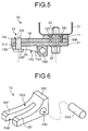
- FIG. 5 is a schematic cross-sectional view illustrating a state before the supporting apparatus for the steering bracket according to the first embodiment is separated.
- FIG. 5 is a cross-sectional view taken along the line A-A direction of FIG. 3 .
- the outline of an electric power steering apparatus 80 will be described with reference to FIGS. 1 to 5 . In the following description, a front of the vehicle when the electric power steering apparatus 80 is attached to the vehicle is simply described as a front and a rear of the vehicle when the electric power steering apparatus 80 is attached to the vehicle is simply
- One end of the lower shaft 85 is connected to the universal joint 84 and the other end thereof is connected to the universal joint 86.
- One end of the pinion shaft 87 is connected to the universal joint 86 and the other end thereof is connected to the steering gear 88.
- the steering gear 88 includes a pinion 88a and a rack 88b.
- the pinion 88a is connected to the pinion shaft 87.
- the rack 88b is engaged with the pinion 88a.
- the steering gear 88 is constituted as a rack-and-pinion type.
- the steering gear 88 converts a rotational motion transmitted to the pinion 88a into a linear motion with the rack 88b.
- the tie rod 89 is connected to the rack 88b.
- the steering force assisting mechanism 83 includes a reduction gear 92 and an electric motor (motor) 70.
- the electric motor 70 is a so-called brushless motor which is described as an example, but the electric motor 70 may be an electric motor provided with a brush (slider) and a commutator.
- the reduction gear 92 is connected to the output shaft 82b.
- the electric motor 70 is an electric motor connected to the reduction gear 92 and for generating auxiliary steering torque.
- the steering shaft 82, the torque sensor 91a, and the reduction gear 92 form a steering column.
- the electric motor configured 70 provides the auxiliary steering torque to the output shaft 82b of the steering column. That is, the electric power steering apparatus 80 according to this embodiment is a column assist system.
- the steering force assisting mechanism 83 of the electric power steering apparatus 80 includes a steering column 50 and a steering bracket 52, referred to as an upper attachment bracket functions, as a mechanism for supporting each parts such as the ECU 90 and the electric motor 70.
- the steering column 50 rotatably supports the input shaft 82a.
- the steering column 50 has a double tube structure constituted by an outer column 51 and an inner column 54 which absorb impact energy at the time of collapse and secure a predetermined collapse contract at a coupling portion to the reduction gear 92.
- the steering bracket 52 is disposed on an upper side of the outer column 51 in a vertical direction.
- the steering bracket 52 is attached to a vehicle body and supports the outer column 51.
- the steering bracket 52 includes an attachment plate portion 52b, a frame-shaped support portion 52a formed integrally with the attachment plate portion 52b, and a tilt mechanism constituted to support the outer column 51.
- the attachment plate portion 52b of the steering bracket 52 is provided with a capsule support portion 59 extending to the outside from the outer column 51.
- the tilt mechanism is formed in the frame-shaped support portion 52a.
- the steering bracket 52 is fixed to a steering bracket supporting apparatus 10 (hereinafter, referred to as a supporting apparatus 10) so that the steering bracket 52 is supported by a vehicle body-side member 21 illustrated in FIG. 5 .
- the supporting state is released by an operation of rotating a tilt lever 53 of the tilt mechanism. By this operation, it is possible to adjust a tilt position of the steering column 50 upward and downward.
- the torque sensor 91a illustrated in FIG. 1 detects a steering force by the driver, transmitted to the input shaft 82a through the steering wheel 81, as steering torque.
- the vehicle speed sensor 91b detects a running speed (vehicle speed) of the vehicle on which the electric power steering apparatus 80 is mounted.
- the ECU 90 is electrically connected to the electric motor 70, the torque sensor 91a, and the vehicle speed sensor 91b.
- the ECU 90 controls the operation of the electric motor 70.
- the ECU 90 acquires a signal from each of the torque sensor 91a and the vehicle speed sensor 91b.
- the ECU 90 acquires steering torque T from the torque sensor 91a, and acquires a vehicle speed signal V of the vehicle from the vehicle speed sensor 91b.
- Power is supplied to the ECU 90 from a power supply unit (for example, buttery on the vehicle) 99 when an ignition switch 98 is turned ON.
- the ECU 90 calculates an auxiliary steering command value for an assist command, based on the steering torque T and the vehicle speed signal V.
- the ECU 90 adjusts a power value X to be supplied to the electric motor 70 based on the calculated auxiliary steering command value.
- the ECU 90 acquires information of an inductive voltage or rotation information of a rotor such as a resolver to be described below, as operation information Y.
- the steering force by a steerer (driver) input to the steering wheel 81 is transmitted to the reduction gear 92 in the steering force assisting mechanism 83 through the input shaft 82a.
- the ECU 90 acquires the steering torque T, which is input to the input shaft 82a, from the torque sensor 91a and acquires the vehicle speed signal V from the vehicle speed sensor 91b. Then, the ECU 90 controls the operation of the electric motor 70.
- the auxiliary steering torque generated by the electric motor 70 is transmitted to the reduction gear 92.
- the steering torque (including the auxiliary steering torque) output through the output shaft 82b is transmitted to the lower shaft 85 through the universal joint 84 and is further transmitted to the pinion shaft 87 through the universal joint 86.
- the steering force transmitted to the pinion shaft 87 is transmitted to the tie rod 89 through the steering gear 88, thereby causing the steering wheel to turn.
- a separation capsule 11 illustrated in FIGS. 3 to 5 is formed by aluminum die-casting.
- the separation capsule 11 is provided with a capsule attachment hole 11h (see FIGS. 3 and 4 ) constituted to fix the separation capsule 11 to the vehicle body-side member 21 with a bolt 22 and a nut 23 illustrated in FIG. 5 .
- the separation capsule 11 has three resin injection holes 12h (first capsule-side hole) communicated with resin injection holes 59h (first bracket-side hole) provided at a capsule support portion 59 of the steering bracket 52, and a resin member 12P straddles the resin injection hole 59h and the resin injection hole 12h in a state before the separation.
- the resin member 12P is a mechanical fuse constituted to be fractured during a secondary collision by shearing force applied to the resin member 12P which is injected into the resin injection hole 12h of the separation capsule 11.
- a separation load causing the fracture of the resin member 12P depends on the material and the sheared cross-sectional area of the resin member 12P.
- a shear pin 13 according to the first embodiment straddles a second bracket-side hole 59I and a second capsule-side hole 11J in the state before the separation so as to withstand impact of, for example, an telescopic operation in an ordinary use.
- the ordinary use includes a condition where inertial or impact is applied due to acceleration and deceleration during a driving operation.
- the shear pin 13 may be made of the same resin as the resin member 12P or be made of a metal. When the shear pin 13 is formed of the resin, the shear pin 13 is fractured simultaneously with the resin member 12P and thus the steering bracket 52 can be separated from the separation capsule 11 fixed to the vehicle body-side member 21 when a considerable load, which an operation of an inertial action body to be described below does not catch up with, is applied in a short time.
- the shear pin 13 includes a cylindrical shear pin body 13B, a head portion 13P which is provided at one end of the shear pin body 13B and has a diameter larger than that of the shear pin body 13B, and a hook portion 13T which is provided at the other end of the shear pin body 13B and is positioned at an edge of the second bracket-side hole 59I of the capsule support portion 59.
- the hook portion 13T having the diameter larger than that of the shear pin body 13B and a thickness smaller than that of the head portion 13P, has a fragile structure.
- FIG. 6 is a perspective view schematically illustrating the inertial action body according to the first embodiment.
- the inertial action body 15 has a shape like a head of a nail puller.
- the inertial action body 15 includes a base portion 15B and two-pronged claw portions 15F and 15F obtained by dividing a part of the base portion 15B with a slit 15M.
- the claw portions 15F and 15F have an inclined surface or a curved surface such that the distance from the surface of the separation capsule 11 increases toward the base portion 15B.
- the inertial action body 15 can convert the inertial action applied thereto to an action to pull out the shear pin 13 from the second bracket-side hole 59I.
- the shear pin 13 penetrates into the slit 15M, and the head portion 13P comes in contact with a surface 15Q of the claw portion 15F.
- the inertial action body 15 is clamped between the head portion 13P of the shear pin 13 and the surface of the separation capsule 11, and a sliding contact surface 15U of inertial action body 15 is firmly adhered to the separation capsule 11. Therefore, frictional force is generated between the sliding contact surface 15U of the inertial action body 15 and the separation capsule 11, so that the movement of the inertial action body 15 is set to be suppressed for a relatively weak impact.
- the inertial action body 15 is provided with the weight portion 15G separately from the base portion 15B, but may be a weight portion in which the center of gravity of the inertial action body 15 gathers due to the material, the shape, and the like of the base portion 15B.
- the weight portion 15G biases the center of gravity of the inertial action body 15 toward the base portion 15B.
- the base portion 15B and the claw portions 15F are made of an iron material such as stainless steel and the weight portion 15G is made of a material such as tungsten carbide having a larger specific gravity than the base portion 15B.
- FIG. 7 is a schematic cross-sectional view illustrating a state where the shear pin is pulled out in the supporting apparatus for the steering bracket according to the first embodiment.
- the inertial action body 15 moves in a direction F toward the front of the vehicle.
- the head portion 13P of the shear pin 13 moves along the surface 15Q and the hook portion 13T illustrated in FIG. 5 is broken.
- the hook portion 13T is deformed to become an end 13Tk to be drawn into the second bracket-side hole 591 and the second capsule-side hole 11J, and is pulled out from the second bracket-side hole 59I as the inertial action body 15 moves.
- the shear pin body 13B of the shear pin 13 drops or is pulled out from the second bracket-side hole 59I in a direction Fu as the inertial action body 15 moves.
- the weight portion 15G moves to the front of the vehicle by the inertia due to the primary collision, and thus the shear pin 13 can be pulled out from the second bracket-side hole 59I with the movement of the weight portion 15.
- FIG. 8 is a schematic cross-sectional view illustrating a state after the supporting apparatus for the steering bracket according to the first embodiment is separated. Subsequently, when an excessive load which exceeds a load set value of the secondary collision is applied to the steering column 50 attached to the vehicle, and the steering column 50 is pushed in the direction F toward the front of the vehicle, a part of the resin member 12P is cut into a resin piece 12Pk and a resin piece 12Pkk. Therefore, the steering column 50 moves to the front of the vehicle to separate the capsule support portion 59 from the separation capsule 11, and the supporting apparatus 10 protects the driver(operator) from a thrust (secondary collision) of a steering wheel.
- the supporting apparatus 10 includes the capsule support portion 59 of the steering bracket 52 supporting the steering column 50, and the separation capsule 11 to fix the vehicle body-side member 21 and the steering bracket 52.
- the capsule support portion 59 includes the first capsule-side hole 12h and the second capsule-side hole 11J opened thereon
- the separation capsule 11 includes the first bracket-side hole 59h and the second bracket-side hole 59I opened thereon.
- the resin member 12P is arranged at a position straddling the first bracket-side hole 59h and the first capsule-side hole 12h before the separation.
- the shear pin 13 is arranged at a position straddling the second bracket-side hole 59I and the second capsule-side hole 11J before the separation.
- the inertial action body 15 moves separately from the steering column by the action of inertia applied independently to the inertial action body 15 and the shear pin 13 can be pulled out from the second bracket-side hole 591 with the movement of the inertial action body 15.
- the inertial action body 15 moves and the shear pin 13 is pulled out from the second bracket-side hole 59I with the movement of the inertial action body 15.
- some of the resin member 12P is cut into the resin piece 12Pk and the resin piece 12Pkk, the steering column thus moves to the front of the vehicle to make the state where the capsule support portion 59 is separated from the separation capsule 11, and the supporting apparatus 10 alleviates the impact caused by the collision (secondary collision) of the driver (operator) with the steering wheel.
- the supporting apparatus 10 can further protect an operator who is light in weight.
- the inertial action body 15 according to the first embodiment is fixed to the separation capsule 11 side, but may be fixed to the capsule support portion 59 side.
- the electric power steering apparatus 80 (steering apparatus) is supported by the supporting apparatus 10 described above. Thus, a part of the supporting structure is cut, which causes lowering of the set value of the separation load at which the steering column 50 moves to the front of the vehicle, therefore the steering apparatus can further protect the operator who is light in weight.
- FIG. 9 is a schematic cross-sectional view illustrating a state before a supporting apparatus for a steering bracket according to a second embodiment is separated.
- FIG. 10 is a schematic cross-sectional view illustrating a state a shear pin of the supporting apparatus for the steering bracket according to the second embodiment is pulled out.
- the same members as those described above are denoted by the same reference numerals and the description thereof will not be presented to avoid duplication.
- FIGS. 9 and 10 with respect to a second bracket-side hole 59I and a second capsule-side hole 11J, one of the second bracket-side hole 59I and the second capsule-side hole 11J, which is located near the head portion 13P of the shear pin 13, has a larger diameter than the other.
- the second capsule-side hole 11J has the larger diameter than the second bracket-side hole 59I.
- the second capsule-side hole 11J holds the posture of the shear pin body 13B before the separation.
- impact such as a primary collision of the vehicle, which exceeds a set value of an operation load in which an inertial action body 15 operates, is applied to the supporting apparatus 10, the inertial action body 15 moves in a direction F toward a front of a vehicle.
- the head portion 13P of the shear pin 13 moves along a surface 15Q and a hook portion 13T illustrated in FIG. 9 is broken.
- the shear pin 13 is deformed to have an end 13Tk, thereby being drawn into the second bracket-side hole 59I and the second capsule-side hole 11J and being pulled out from the second bracket-side hole 59I as the inertial action body 15 moves.
- the shear pin body 13B of the shear pin 13 drops or is pulled out from the second bracket-side hole 59I in a direction Fu as the inertial action body 15 moves.
- the head portion is not necessarily pulled out parallel to the direction Fu.
- the second capsule-side hole 11J has a larger diameter than the second bracket-side hole 59I, it is possible to increase the probability of the pulling-out even when the posture of the shear pin body 13B is inclined.
- FIG. 11 is a schematic cross-sectional view illustrating a state before a supporting apparatus for a steering bracket according to a third embodiment is separated.
- the same members as those described above are denoted by the same reference numerals and the description thereof will not be presented to avoid duplication.
- a guide surface 59G is provided on the surface of a capsule support portion 59 or a separation capsule 11 of a steering bracket to guide a movement direction of an inertial action body 15 due to action of inertia. For example, even when a moment load including a rotational component is applied to a weight portion 15G, a shear pin 13 can be pulled out along the guide surface 59G by the inertial action body 15.
- FIG. 12 is a schematic cross-sectional view illustrating a state before a supporting apparatus for a steering bracket according to a fourth embodiment is separated.
- a shear pin 13 according to the fourth embodiment includes a cylindrical shear pin body 13B, a head portion 13P which is provided at one end of the shear pin body 13B and has a diameter larger than that of the shear pin body 13B, and a hook portion 13TF which is provided at the other end of the shear pin body 13B and is positioned at an edge of a second bracket-side hole 591 of a capsule support portion 59.
- a hollow portion 13S with a bottom is opened in the shear pin body 13B and elastic force is urged to the outside of a hook portion 13TF. Therefore, the shear pin 13 according to the fourth embodiment is constituted such that the diameter of the hook portion 13TF facilely decreases and it is possible to pull out the shear pin 13 without breakage.
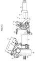
- FIG. 13 is a plan view schematically illustrating a supporting apparatus for a steering bracket constituted to attach a steering column to a vehicle.
- FIG. 14 is a perspective view schematically illustrating a portion constituted to attach the steering column to the vehicle.
- FIG. 15 is a perspective view schematically illustrating a portion constituted to attach a steering column according to a fifth embodiment to the vehicle.
- FIG. 15 is a cross-sectional view as viewed in the line B-B direction of FIG. 13 .
- FIG. 16 is a schematic cross-sectional view illustrating a state before a supporting apparatus for a steering bracket according to the fifth embodiment is separated.
- the same members as those described above are denoted by the same reference numerals and the description thereof will not be presented to avoid duplication.
- a separation capsule 11 illustrated in FIGS. 13 to 16 is formed by aluminum die-casting.
- the separation capsule 11 is provided with a capsule attachment hole 11h (see FIGS. 3 and 15 ) constituted to fix a separation capsule 11 to a vehicle body-side member 21 with a bolt 22 and a nut 23 illustrated in FIG. 16 .
- the separation capsule 11 has three resin injection holes 12h (first capsule-side hole) communicated with resin injection holes 59h (first bracket-side hole) provided at a capsule support portion 59 of the steering bracket, and a resin member 12P straddles the resin injection hole 59h and the resin injection hole 12h in a state before the separation.
- the resin member 12P injected into the resin injection hole 12h of the separation capsule 11 is a mechanical fuse constituted to be fractured by shearing force applied during a secondary collision.
- a separation load causing the fracture of the resin member 12P depends on the material and the sheared cross-sectional area of the resin member 12P.
- a shear pin 13D according to the fifth embodiment straddles a second bracket-side hole 11I and the second capsule-side hole 11J in the state before the separation so as to withstand impact of, for example, an telescopic operation in an ordinary use.
- the ordinary use includes a condition where inertial or impact is applied due to acceleration and deceleration during a driving operation.
- the shear pin 13D may be made of the same resin as the resin member 12P and be made of a metal. When the shear pin 13D is formed of the resin, the shear pin 13D is fractured simultaneously with the resin member 12P and thus the steering bracket 52 can be separated from the separation capsule 11 fixed to the vehicle body-side member 21, when a considerable load is applied in a short time such that an operation of a cam mechanism to be described below does not catch up with the considerable load.
- the shear pin 13D includes a head portion 13P which is provided at one end of a shear pin body of solid cylindrical body and has a diameter larger than that of the shear pin body.
- a pin tip 13PT which is the other end of the shear pin body of the shear pin 13D is inserted into the second bracket-side hole 11I of the capsule support portion 59 in the state before the separation and is positioned in a cam mechanism 13A. The pin tip 13PT may be penetrated through the second bracket-side hole 11I.
- the cam mechanism 13A includes a cam rotor 13CM interlocking with the shear pin 13D, and a cam stator 13CF fixed to the capsule support portion 59 or the separation capsule 11 of the steering bracket.
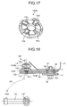
- FIG. 17 is a perspective view schematically illustrating protrusion portions of the cam rotor of the cam mechanism according to the fifth embodiment. As illustrated in FIG. 17 , the cam rotor 13CM has protrusion portions 13Q on a surface facing the cam stator 13CF.
- the cam stator 13CF has protrusion portions 13FB, which are similar to the protrusion portions 13Q illustrated in FIG. 17 , on a surface facing the cam rotor 13CM.
- the protrusion portions 13FB of the cam stator 13CF are located at recessed portions between the protrusion portions 13Q of the cam rotor 13CM, and the protrusion portions 13Q and the protrusion portions 13FB have the similar height, the protrusion portions 13Q and the protrusion portions 13FB are engaged with each other.
- the phase of the protrusion portions 13Q coincides with that of the protrusion portions 13FB.
- the protrusion portions 13Q ride over the protrusion portions 13FB, the distance between the cam rotor 13CM and the cam stator 13CF increases.
- the shear pin 13D penetrates a lever member 13L to be described below and a washer 13w, and the head portion 13P is supported by the washer 13w. For this reason, the distance between the cam rotor 13CM and the cam stator 13CF increases depending on the rotation amount of the cam rotor 13CM which rotates relative to the cam stator 13CF.
- An insertion length of the shear pin 13D to be inserted into the second bracket-side hole 11I varies depending on the distance between the cam rotor 13CM and the cam stator 13CF.
- the cam mechanism 13A can convert the rotation motion, which depends on the amount of rotation due to the inertial action, to a motion in which the shear pin 13D is pulled out from the second bracket-side hole 11I.
- the lever member 13L is a rod-shaped member which rotates interlocking with the rotation of the cam rotor 13CM. Since the lever member 13L applies the load to a part of the cam rotor 13CM, the lever member 13L is a member which is used to move the center of gravity of the cam rotor toward the outside from a rotation center of the cam rotor 13CM. Thus, it is possible to set a set value of an operation load in which the cam mechanism 13A operates.
- the lever member 13L is provided with a weight portion 13W at a side far from the cam rotor 13CM.
- the weight portion 13W is made of a material such as tungsten carbide having a larger specific gravity than the cam rotor 13CM.
- the lever member 13L is disposed in a direction orthogonal to the front of the vehicle when the surface of the separation capsule 11 is viewed in a plan view.
- the lever member 13L of the cam mechanism 13A rotates in a direction FR toward the front of the vehicle.
- the distance between the cam rotor 13CM and the cam stator 13CF increases depending on the rotation amount of the cam rotor 13CM which rotates relative to the cam stator 13CF.
- the insertion amount of the shear pin 13D to be inserted into the second bracket-side hole 11I decreases with the movement of the cam rotor 13CM. As a result, as illustrated in FIG. 18 , the shear pin 13D is pulled out from the second bracket-side hole 111 with the movement of the cam rotor 13CM.
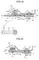
- FIG. 19 is a schematic cross-sectional view illustrating a state after the supporting apparatus for the steering bracket according to the fifth embodiment is separated. Subsequently, when an excessive load exceeding a load set value of the secondary collision is applied to the steering column attached to the vehicle and the steering column is pushed to the front of the vehicle, a part of the resin member 12P is cut into a resin piece 12Pk and a resin piece 12Pkk, the steering column moves to the front of the vehicle to make the state where the capsule support portion 59 is separated from the separation capsule 11, and the supporting apparatus 10 alleviates the impact caused by the collision (secondary collision) of the driver (operator) with the steering wheel.
- the supporting apparatus 10 includes the capsule support portion 59 of the steering bracket 52, which supports the steering column 50, and the separation capsule 11 to fix the vehicle body-side member 21 and the steering bracket, and the capsule support portion 59 includes the first capsule-side hole 12h and the second capsule-side hole 11J opened thereon, and the separation capsule 11 includes the first bracket-side hole 59h and the second bracket-side hole 11I opened thereon.
- the shear pin 13D is arranged at a position straddling the first bracket-side hole 59h and the first capsule-side hole 12h before the separation.
- the resin member 12P is arranged at a position straddling the second bracket-side hole 11I and the second capsule-side hole 11J before the separation.
- the cam mechanism 13A rotates by the action of inertia. That is, the weight portion 13W rotates around the shear pin 13D by the inertia due to the primary collision and moves to the front of the vehicle.
- the shear pin 13D can be pulled out from the second bracket-side hole 11I with the rotation of the cam mechanism 13A.
- the cam mechanism 13A according to the fifth embodiment is fixed to the surface of the capsule support portion 59, but may be fixed to the separation capsule 11 side.
- An electric power steering apparatus 80 (steering apparatus) is supported by the supporting apparatus 10 described above. Thus, a part of the supporting structure is cut, which lowers the set value of the separation load at which the steering column 50 moves to the front of the vehicle, so that the steering apparatus can further protect the operator who is light in weight.
- FIG. 20 is a schematic cross-sectional view illustrating a state before a supporting apparatus for a steering bracket according to a sixth embodiment is separated.
- the same members as those described above are denoted by the same reference numerals and the description thereof will not be presented to avoid duplication.
- the function of the cam rotor 13CM according to the fifth embodiment may be integrated with a lever member 13L.
- the lever member 13L is provided with protrusion portions 13Q.
- the lever member 13L may be integrated with or fixed to a head portion 13P of a shear pin 13D.
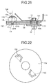
- FIG. 21 is a schematic cross-sectional view illustrating a state before a supporting apparatus for a steering bracket according to a seventh embodiment is separated.
- FIG. 22 is a schematic diagram of a washer of the supporting apparatus for the steering bracket according to the seventh embodiment.
- the function of the cam rotor 13CM according to the fifth embodiment may be integrated with a washer 13w.
- the washer 13w is provided with protrusion portions 13Q which are bendable by a slit. The protrusion portions 13Q are cut and raised, and thus the washer 13w protrudes toward a protrusion portion 13FB of the lever member 13L.
Landscapes
- Engineering & Computer Science (AREA)
- Mechanical Engineering (AREA)
- Chemical & Material Sciences (AREA)
- Combustion & Propulsion (AREA)
- Transportation (AREA)
- General Engineering & Computer Science (AREA)
- Steering Controls (AREA)
Description
- The present invention relates to a steering-bracket supporting apparatus, i.e. a supporting apparatus for fixing a steering bracket to a vehicle body and also relates to a steering apparatus.
- Patent Literatures 1 and 2 disclose techniques of a separation capsule in which when an excessive load is applied to a steering column attached to a vehicle and the steering column is pushed to the front of the vehicle, a part of the supporting structure is separated and the steering column thus moves to the front of the vehicle, thereby protecting a driver (operator) from a thrust (secondary collision) of a steering wheel.
-
- Patent Literature 1:
JP 63-019467 U1 - Patent Literature 2:
JP 07-081586 A - In the techniques disclosed in Patent Literatures 1 and 2, since a set value of the separation load at which the steering column moves to the front of the vehicle is lowered by cutting a part of the supporting structure, there is a possibility of occurrence in malfunction, in a case of trying to protect an operator who is light in weight.
- The present invention has been made in view of the above problem. An object of the present invention is to provide a steering-bracket supporting apparatus and a steering apparatus which are capable of suppressing the malfunction in an ordinary use even when a part of the supporting structure is separated and thus the set value of the separation load at which the steering column moves to the front of the vehicle.
- It is an object of the present invention to at least partially solve the problems in the conventional technology. According to an aspect of the invention, a supporting apparatus for a steering bracket includes, a steering bracket supporting a steering column, the steering bracket including a first capsule-side hole and a second capsule-side hole opened thereon; a separation capsule to fix a vehicle body-side member to the steering bracket, the separation capsule including a first bracket-side hole and a second bracket-side hole opened thereon; a resin member arranged at a position straddling the first bracket-side hole and the first capsule-side hole in a state before separation; a shear pin arranged at a position straddling the second bracket-side hole and the second capsule-side hole in a state before separation; and a cam mechanism including a rotatable weight portion to pull out the shear pin from the second bracket-side hole, the weight portion constituted to rotate around the shear pin by inertia due to a primary collision and to move to a front of a vehicle, and the cam mechanism constituted to pull out the shear pin from the bracket-side hole by a rotation of the weight portion.
- When a load is applied to the steering column, which is attached to the vehicle, by the impact in the ordinary use, the steering column is pushed to the front of the vehicle and the resin member is subjected to the shearing force, and the shearing force is similarly applied to the shear pin. Thus, the fracture of the resin member is suppressed and the malfunction is suppressed during the ordinary use. Meanwhile, in the case of the collision (primary collision) of the vehicle, the shear pin is pulled out by a cam mechanism so that a part of the supporting structure is cut and the set value of the separation load at which the steering column moves to the front of the vehicle is lowered, thereby the supporting apparatus for the steering bracket can alleviate the impact of an operator who is light in weight.
- As a desirable aspect of the invention, the cam mechanism includes a cam rotor interlocking with the shear pin and a cam stator fixed to the steering bracket or the separation capsule, the cam rotor is constituted to rotate relative to the cam stator and to change an insertion length of the shear pin into the second bracket-side hole depending on the rotation amount of the cam rotor. Thus, the cam mechanism can convert a rotating motion to a motion in which the shear pin is pulled out from the second bracket-side hole, depending on the amount of rotation due to the action of inertia.
- As a desirable aspect of the invention, the cam rotor includes a lever member to move a center of gravity outward from a rotation center of the cam rotor. Thus, it is possible to set a set value of an operation load in which the cam mechanism operates.
- As a desirable aspect of the invention, the weight portion is located at a side far from the cam rotor of the lever member. This makes it possible to increase the amount of movement of the center of gravity toward the outside rather than the rotation center of the cam rotor.
- As a desirable aspect of the invention, a steering apparatus is supported by the supporting apparatus for the steering bracket as described above. Thus, a part of the supporting structure is cut and thus the set value of the separation load at which the steering column moves to the front of the vehicle is lowered, so that the steering apparatus can further protect the operator who is light in weight.
- According to the present invention, it is possible to provide a steering-bracket supporting apparatus and a steering apparatus which can suppress the malfunction in an ordinary use even when a part of the supporting structure is cut and thus the set value of the separation load at which a steering column moves to the front of the vehicle is lowered.
-
-
FIG. 1 is a constitution diagram of an electric power steering apparatus provided with an electric motor according to a first embodiment. -
FIG. 2 is a side view schematically illustrating a periphery of a steering column. -
FIG. 3 is a plan view schematically illustrating a supporting apparatus for a steering bracket that is used to attach a steering column to a vehicle. -
FIG. 4 is a perspective view schematically illustrating a portion in which the steering column is attached to the vehicle. -
FIG. 5 is a schematic cross-sectional view illustrating a state before the supporting apparatus for the steering bracket according to the first embodiment is separated. -
FIG. 6 is a perspective view schematically illustrating an inertial action body according to the first embodiment. -
FIG. 7 is a schematic cross-sectional view illustrating a state where the shear pin is pulled out in the supporting apparatus for the steering bracket according to the first embodiment. -
FIG. 8 is a schematic cross-sectional view illustrating a state after the supporting apparatus for the steering bracket according to the first embodiment is separated. -
FIG. 9 is a schematic cross-sectional view illustrating a state before a supporting apparatus for a steering bracket according to a second embodiment is separated. -
FIG. 10 is a schematic cross-sectional view illustrating a state where a shear pin of the supporting apparatus for the steering bracket according to the second embodiment is pulled out. -
FIG. 11 is a schematic cross-sectional view illustrating a state before a supporting apparatus for a steering bracket according to a third embodiment is separated. -
FIG. 12 is a schematic cross-sectional view illustrating a state before a supporting apparatus for a steering bracket according to a fourth embodiment is separated. -
FIG. 13 is a plan view schematically illustrating a supporting apparatus for a steering bracket to attach a steering column to a vehicle. -
FIG. 14 is a perspective view schematically illustrating a portion where the steering column is attached to the vehicle. -
FIG. 15 is a perspective view schematically illustrating a portion where a steering column according to a fifth embodiment is attached to the vehicle. -
FIG. 16 is a schematic cross-sectional view illustrating a state before a supporting apparatus for a steering bracket according to the fifth embodiment is separated. -
FIG. 17 is a perspective view schematically illustrating protrusion portions of a cam rotor of a cam mechanism according to the fifth embodiment. -
FIG. 18 is a schematic cross-sectional view illustrating a state a shear pin of the supporting apparatus for the steering bracket according to the fifth embodiment is pulled out. -
FIG. 19 is a schematic cross-sectional view illustrating a state after the supporting apparatus for the steering bracket according to the fifth embodiment is separated. -
FIG. 20 is a schematic cross-sectional view illustrating a state before a supporting apparatus for a steering bracket according to a sixth embodiment is separated. -
FIG. 21 is a schematic cross-sectional view illustrating a state before a supporting apparatus for a steering bracket according to a seventh embodiment is separated. -
FIG. 22 is a schematic diagram of a washer of the supporting apparatus for the steering bracket according to the seventh embodiment. - Embodiments of the present invention will be described in detail with reference to the drawings. The present invention is not limited by the contents described in the following embodiments. In addition, elements described below include those that are easily conceived by a person skilled in the art and that are substantially the same. Further, the elements described below can be properly combined.
-
FIG. 1 is a constitution diagram an electric power steering apparatus provided with an electric motor according to a first embodiment.FIG. 2 is a side view schematically illustrating a periphery of a steering column.FIG. 3 is a plan view schematically illustrating a supporting apparatus for a steering bracket that is used to attach a steering column to a vehicle.FIG. 4 is a perspective view schematically illustrating a portion in which the steering column is attached to the vehicle.FIG. 5 is a schematic cross-sectional view illustrating a state before the supporting apparatus for the steering bracket according to the first embodiment is separated.FIG. 5 is a cross-sectional view taken along the line A-A direction ofFIG. 3 . The outline of an electricpower steering apparatus 80 will be described with reference toFIGS. 1 to 5 . In the following description, a front of the vehicle when the electricpower steering apparatus 80 is attached to the vehicle is simply described as a front and a rear of the vehicle when the electricpower steering apparatus 80 is attached to the vehicle is simply described as a rear. - In the order in which a force is transmitted by a driver (operator), the electric
power steering apparatus 80 includes a steering wheel 81, a steeringshaft 82, a steeringforce assisting mechanism 83, anuniversal joint 84, alower shaft 85, anuniversal joint 86, apinion shaft 87, asteering gear 88, and atie rod 89. In addition, the electricpower steering apparatus 80 includes an ECU (Electronic Control Unit) 90 and atorque sensor 91a. Avehicle speed sensor 91b is provided in the vehicle and inputs a vehicle speed signal V to theECU 90 using a CAN (Controller Area Network) communication. - The steering
shaft 82 includes aninput shaft 82a and anoutput shaft 82b. One end of theinput shaft 82a is connected to the steering wheel 81 and the other end thereof is connected to the steeringforce assisting mechanism 83 through thetorque sensor 91a. One end of theoutput shaft 82b is connected to the steeringforce assisting mechanism 83 and the other end thereof is connected to theuniversal joint 84. In this embodiment, theinput shaft 82a and theoutput shaft 82b are formed of a magnetic material such as iron. - One end of the
lower shaft 85 is connected to theuniversal joint 84 and the other end thereof is connected to theuniversal joint 86. One end of thepinion shaft 87 is connected to theuniversal joint 86 and the other end thereof is connected to thesteering gear 88. - The
steering gear 88 includes apinion 88a and a rack 88b. Thepinion 88a is connected to thepinion shaft 87. The rack 88b is engaged with thepinion 88a. Thesteering gear 88 is constituted as a rack-and-pinion type. Thesteering gear 88 converts a rotational motion transmitted to thepinion 88a into a linear motion with the rack 88b. Thetie rod 89 is connected to the rack 88b. - The steering
force assisting mechanism 83 includes areduction gear 92 and an electric motor (motor) 70. Further, theelectric motor 70 is a so-called brushless motor which is described as an example, but theelectric motor 70 may be an electric motor provided with a brush (slider) and a commutator. Thereduction gear 92 is connected to theoutput shaft 82b. Theelectric motor 70 is an electric motor connected to thereduction gear 92 and for generating auxiliary steering torque. In the electricpower steering apparatus 80, the steeringshaft 82, thetorque sensor 91a, and thereduction gear 92 form a steering column. The electric motor configured 70 provides the auxiliary steering torque to theoutput shaft 82b of the steering column. That is, the electricpower steering apparatus 80 according to this embodiment is a column assist system. - As illustrated in
FIG. 2 , the steeringforce assisting mechanism 83 of the electricpower steering apparatus 80 includes asteering column 50 and asteering bracket 52, referred to as an upper attachment bracket functions, as a mechanism for supporting each parts such as theECU 90 and theelectric motor 70. Thesteering column 50 rotatably supports theinput shaft 82a. Thesteering column 50 has a double tube structure constituted by anouter column 51 and aninner column 54 which absorb impact energy at the time of collapse and secure a predetermined collapse contract at a coupling portion to thereduction gear 92. - The
steering bracket 52 is disposed on an upper side of theouter column 51 in a vertical direction. Thesteering bracket 52 is attached to a vehicle body and supports theouter column 51. Thesteering bracket 52 includes anattachment plate portion 52b, a frame-shapedsupport portion 52a formed integrally with theattachment plate portion 52b, and a tilt mechanism constituted to support theouter column 51. Theattachment plate portion 52b of thesteering bracket 52 is provided with acapsule support portion 59 extending to the outside from theouter column 51. The tilt mechanism is formed in the frame-shapedsupport portion 52a. Thesteering bracket 52 is fixed to a steering bracket supporting apparatus 10 (hereinafter, referred to as a supporting apparatus 10) so that thesteering bracket 52 is supported by a vehicle body-side member 21 illustrated inFIG. 5 . - The supporting state is released by an operation of rotating a
tilt lever 53 of the tilt mechanism. By this operation, it is possible to adjust a tilt position of thesteering column 50 upward and downward. - The
torque sensor 91a illustrated inFIG. 1 detects a steering force by the driver, transmitted to theinput shaft 82a through the steering wheel 81, as steering torque. Thevehicle speed sensor 91b detects a running speed (vehicle speed) of the vehicle on which the electricpower steering apparatus 80 is mounted. TheECU 90 is electrically connected to theelectric motor 70, thetorque sensor 91a, and thevehicle speed sensor 91b. - The
ECU 90 controls the operation of theelectric motor 70. In addition, theECU 90 acquires a signal from each of thetorque sensor 91a and thevehicle speed sensor 91b. In other words, theECU 90 acquires steering torque T from thetorque sensor 91a, and acquires a vehicle speed signal V of the vehicle from the vehicle speed sensor 91b. Power is supplied to theECU 90 from a power supply unit (for example, buttery on the vehicle) 99 when anignition switch 98 is turned ON. TheECU 90 calculates an auxiliary steering command value for an assist command, based on the steering torque T and the vehicle speed signal V. Then, theECU 90 adjusts a power value X to be supplied to theelectric motor 70 based on the calculated auxiliary steering command value. From theelectric motor 70, theECU 90 acquires information of an inductive voltage or rotation information of a rotor such as a resolver to be described below, as operation information Y. - The steering force by a steerer (driver) input to the steering wheel 81 is transmitted to the
reduction gear 92 in the steeringforce assisting mechanism 83 through theinput shaft 82a. At this time, theECU 90 acquires the steering torque T, which is input to theinput shaft 82a, from thetorque sensor 91a and acquires the vehicle speed signal V from thevehicle speed sensor 91b. Then, theECU 90 controls the operation of theelectric motor 70. The auxiliary steering torque generated by theelectric motor 70 is transmitted to thereduction gear 92. - The steering torque (including the auxiliary steering torque) output through the
output shaft 82b is transmitted to thelower shaft 85 through theuniversal joint 84 and is further transmitted to thepinion shaft 87 through theuniversal joint 86. The steering force transmitted to thepinion shaft 87 is transmitted to thetie rod 89 through thesteering gear 88, thereby causing the steering wheel to turn. - A
separation capsule 11 illustrated inFIGS. 3 to 5 is formed by aluminum die-casting. Theseparation capsule 11 is provided with acapsule attachment hole 11h (seeFIGS. 3 and 4 ) constituted to fix theseparation capsule 11 to the vehicle body-side member 21 with abolt 22 and anut 23 illustrated inFIG. 5 . In addition, theseparation capsule 11 has threeresin injection holes 12h (first capsule-side hole) communicated withresin injection holes 59h (first bracket-side hole) provided at acapsule support portion 59 of thesteering bracket 52, and aresin member 12P straddles theresin injection hole 59h and theresin injection hole 12h in a state before the separation. - The
resin member 12P is a mechanical fuse constituted to be fractured during a secondary collision by shearing force applied to theresin member 12P which is injected into theresin injection hole 12h of theseparation capsule 11. A separation load causing the fracture of theresin member 12P depends on the material and the sheared cross-sectional area of theresin member 12P. Even when some of theresin member 12P is cut and thus the set value of the separation load, at which the steering column moves in the front of the vehicle, is lowered, ashear pin 13 according to the first embodiment straddles a second bracket-side hole 59I and a second capsule-side hole 11J in the state before the separation so as to withstand impact of, for example, an telescopic operation in an ordinary use. The ordinary use includes a condition where inertial or impact is applied due to acceleration and deceleration during a driving operation. - In the ordinary use, when a load is applied to the steering column, which is attached to the vehicle, by the impact of, for example, telescopic operation, if the steering column is pushed to the front of the vehicle, the
resin member 12P is subjected to the shearing force and the shearing force is similarly applied to theshear pin 13. Thus, the fracture of theresin member 12P is suppressed and the malfunction is suppressed during the ordinary use. - The
shear pin 13 may be made of the same resin as theresin member 12P or be made of a metal. When theshear pin 13 is formed of the resin, theshear pin 13 is fractured simultaneously with theresin member 12P and thus thesteering bracket 52 can be separated from theseparation capsule 11 fixed to the vehicle body-side member 21 when a considerable load, which an operation of an inertial action body to be described below does not catch up with, is applied in a short time. - As illustrated in
FIG. 5 , theshear pin 13 includes a cylindricalshear pin body 13B, ahead portion 13P which is provided at one end of theshear pin body 13B and has a diameter larger than that of theshear pin body 13B, and ahook portion 13T which is provided at the other end of theshear pin body 13B and is positioned at an edge of the second bracket-side hole 59I of thecapsule support portion 59. Thehook portion 13T, having the diameter larger than that of theshear pin body 13B and a thickness smaller than that of thehead portion 13P, has a fragile structure. - An
inertial action body 15 is clamped and fixed between thehead portion 13P of theshear pin 13 and the surface of theseparation capsule 11.FIG. 6 is a perspective view schematically illustrating the inertial action body according to the first embodiment. As illustrated inFIGS. 5 and 6 , theinertial action body 15 has a shape like a head of a nail puller. Theinertial action body 15 includes abase portion 15B and two-pronged claw portions base portion 15B with aslit 15M. Theclaw portions separation capsule 11 increases toward thebase portion 15B. Thus, theinertial action body 15 can convert the inertial action applied thereto to an action to pull out theshear pin 13 from the second bracket-side hole 59I. Theshear pin 13 penetrates into theslit 15M, and thehead portion 13P comes in contact with asurface 15Q of theclaw portion 15F. As a result, as described above, theinertial action body 15 is clamped between thehead portion 13P of theshear pin 13 and the surface of theseparation capsule 11, and a slidingcontact surface 15U ofinertial action body 15 is firmly adhered to theseparation capsule 11. Therefore, frictional force is generated between the slidingcontact surface 15U of theinertial action body 15 and theseparation capsule 11, so that the movement of theinertial action body 15 is set to be suppressed for a relatively weak impact. - As illustrated in
FIG. 6 , in theinertial action body 15, aweight portion 15G is inserted into ahole 15H such that the center of gravity of theinertial action body 15 gathers to thebase portion 15B. Thus, it is possible to set a set value of an operation load in which theinertial action body 15 operates. In the first embodiment, theinertial action body 15 is provided with theweight portion 15G separately from thebase portion 15B, but may be a weight portion in which the center of gravity of theinertial action body 15 gathers due to the material, the shape, and the like of thebase portion 15B. Theweight portion 15G biases the center of gravity of theinertial action body 15 toward thebase portion 15B. - As illustrated in
FIG. 6 , in theinertial action body 15, thebase portion 15B and theclaw portions 15F are made of an iron material such as stainless steel and theweight portion 15G is made of a material such as tungsten carbide having a larger specific gravity than thebase portion 15B. -
FIG. 7 is a schematic cross-sectional view illustrating a state where the shear pin is pulled out in the supporting apparatus for the steering bracket according to the first embodiment. For example, when an impact such as a primary collision of the vehicle, which exceeds the set value of the operation load in which theinertial action body 15 operates, is applied to the supportingapparatus 10, theinertial action body 15 moves in a direction F toward the front of the vehicle. Thehead portion 13P of theshear pin 13 moves along thesurface 15Q and thehook portion 13T illustrated inFIG. 5 is broken. Alternatively, thehook portion 13T is deformed to become an end 13Tk to be drawn into the second bracket-side hole 591 and the second capsule-side hole 11J, and is pulled out from the second bracket-side hole 59I as theinertial action body 15 moves. As a result, theshear pin body 13B of theshear pin 13 drops or is pulled out from the second bracket-side hole 59I in a direction Fu as theinertial action body 15 moves. Thus, theweight portion 15G moves to the front of the vehicle by the inertia due to the primary collision, and thus theshear pin 13 can be pulled out from the second bracket-side hole 59I with the movement of theweight portion 15. -
FIG. 8 is a schematic cross-sectional view illustrating a state after the supporting apparatus for the steering bracket according to the first embodiment is separated. Subsequently, when an excessive load which exceeds a load set value of the secondary collision is applied to thesteering column 50 attached to the vehicle, and thesteering column 50 is pushed in the direction F toward the front of the vehicle, a part of theresin member 12P is cut into a resin piece 12Pk and a resin piece 12Pkk. Therefore, thesteering column 50 moves to the front of the vehicle to separate thecapsule support portion 59 from theseparation capsule 11, and the supportingapparatus 10 protects the driver(operator) from a thrust (secondary collision) of a steering wheel. - As described above, the supporting
apparatus 10 includes thecapsule support portion 59 of thesteering bracket 52 supporting thesteering column 50, and theseparation capsule 11 to fix the vehicle body-side member 21 and thesteering bracket 52. Thecapsule support portion 59 includes the first capsule-side hole 12h and the second capsule-side hole 11J opened thereon, and theseparation capsule 11 includes the first bracket-side hole 59h and the second bracket-side hole 59I opened thereon. Theresin member 12P is arranged at a position straddling the first bracket-side hole 59h and the first capsule-side hole 12h before the separation. Theshear pin 13 is arranged at a position straddling the second bracket-side hole 59I and the second capsule-side hole 11J before the separation. Theinertial action body 15 moves separately from the steering column by the action of inertia applied independently to theinertial action body 15 and theshear pin 13 can be pulled out from the second bracket-side hole 591 with the movement of theinertial action body 15. - For this reason, when the load is applied to the
steering column 50, which is attached to the vehicle, by the impact in the ordinary use, if thesteering column 50 is pushed in the direction F toward the front of the vehicle, theresin member 12P is subjected to the shearing force and the shearing force is similarly applied to theshear pin 13. Thus, the fracture of theresin member 12P is suppressed and the malfunction is suppressed during the ordinary use. - When the excessive load which exceeds the load set value of the secondary collision is applied to the steering column attached to the vehicle and the
steering column 50 is pushed in the Direction F toward the front of the vehicle, theinertial action body 15 moves and theshear pin 13 is pulled out from the second bracket-side hole 59I with the movement of theinertial action body 15. Thereafter, some of theresin member 12P is cut into the resin piece 12Pk and the resin piece 12Pkk, the steering column thus moves to the front of the vehicle to make the state where thecapsule support portion 59 is separated from theseparation capsule 11, and the supportingapparatus 10 alleviates the impact caused by the collision (secondary collision) of the driver (operator) with the steering wheel. As a result, a part of the supporting structure is cut, which causes lowering of the set value of the separation load at which thesteering column 50 moves in the Direction F toward the front of the vehicle, therefore the supportingapparatus 10 can further protect an operator who is light in weight. - The
inertial action body 15 according to the first embodiment is fixed to theseparation capsule 11 side, but may be fixed to thecapsule support portion 59 side. The electric power steering apparatus 80 (steering apparatus) is supported by the supportingapparatus 10 described above. Thus, a part of the supporting structure is cut, which causes lowering of the set value of the separation load at which thesteering column 50 moves to the front of the vehicle, therefore the steering apparatus can further protect the operator who is light in weight. -
FIG. 9 is a schematic cross-sectional view illustrating a state before a supporting apparatus for a steering bracket according to a second embodiment is separated.FIG. 10 is a schematic cross-sectional view illustrating a state a shear pin of the supporting apparatus for the steering bracket according to the second embodiment is pulled out. The same members as those described above are denoted by the same reference numerals and the description thereof will not be presented to avoid duplication. As illustrated inFIGS. 9 and 10 , with respect to a second bracket-side hole 59I and a second capsule-side hole 11J, one of the second bracket-side hole 59I and the second capsule-side hole 11J, which is located near thehead portion 13P of theshear pin 13, has a larger diameter than the other. For example, the second capsule-side hole 11J has the larger diameter than the second bracket-side hole 59I. Thus, as illustrated inFIG. 9 , the second capsule-side hole 11J holds the posture of theshear pin body 13B before the separation. For example, when impact such as a primary collision of the vehicle, which exceeds a set value of an operation load in which aninertial action body 15 operates, is applied to the supportingapparatus 10, theinertial action body 15 moves in a direction F toward a front of a vehicle. Thehead portion 13P of theshear pin 13 moves along asurface 15Q and ahook portion 13T illustrated inFIG. 9 is broken. Alternatively, theshear pin 13 is deformed to have an end 13Tk, thereby being drawn into the second bracket-side hole 59I and the second capsule-side hole 11J and being pulled out from the second bracket-side hole 59I as theinertial action body 15 moves. As a result, theshear pin body 13B of theshear pin 13 drops or is pulled out from the second bracket-side hole 59I in a direction Fu as theinertial action body 15 moves. In this case, as illustrated inFIG. 10 , with respect to the relation between thesurface 15Q and thehead portion 13P, when thesurface 15Q has an inclined surface or a curved surface, the head portion is not necessarily pulled out parallel to the direction Fu. As in the second embodiment, when the second capsule-side hole 11J has a larger diameter than the second bracket-side hole 59I, it is possible to increase the probability of the pulling-out even when the posture of theshear pin body 13B is inclined. -
FIG. 11 is a schematic cross-sectional view illustrating a state before a supporting apparatus for a steering bracket according to a third embodiment is separated. The same members as those described above are denoted by the same reference numerals and the description thereof will not be presented to avoid duplication. As illustrated inFIG. 11 , aguide surface 59G is provided on the surface of acapsule support portion 59 or aseparation capsule 11 of a steering bracket to guide a movement direction of aninertial action body 15 due to action of inertia. For example, even when a moment load including a rotational component is applied to aweight portion 15G, ashear pin 13 can be pulled out along theguide surface 59G by theinertial action body 15. -
FIG. 12 is a schematic cross-sectional view illustrating a state before a supporting apparatus for a steering bracket according to a fourth embodiment is separated. The same members as those described above are denoted by the same reference numerals and the description thereof will not be presented to avoid duplication. As illustrated inFIG. 12 , ashear pin 13 according to the fourth embodiment includes a cylindricalshear pin body 13B, ahead portion 13P which is provided at one end of theshear pin body 13B and has a diameter larger than that of theshear pin body 13B, and a hook portion 13TF which is provided at the other end of theshear pin body 13B and is positioned at an edge of a second bracket-side hole 591 of acapsule support portion 59. Ahollow portion 13S with a bottom is opened in theshear pin body 13B and elastic force is urged to the outside of a hook portion 13TF. Therefore, theshear pin 13 according to the fourth embodiment is constituted such that the diameter of the hook portion 13TF facilely decreases and it is possible to pull out theshear pin 13 without breakage. -
FIG. 13 is a plan view schematically illustrating a supporting apparatus for a steering bracket constituted to attach a steering column to a vehicle.FIG. 14 is a perspective view schematically illustrating a portion constituted to attach the steering column to the vehicle.FIG. 15 is a perspective view schematically illustrating a portion constituted to attach a steering column according to a fifth embodiment to the vehicle.FIG. 15 is a cross-sectional view as viewed in the line B-B direction ofFIG. 13 .FIG. 16 is a schematic cross-sectional view illustrating a state before a supporting apparatus for a steering bracket according to the fifth embodiment is separated. The same members as those described above are denoted by the same reference numerals and the description thereof will not be presented to avoid duplication. Aseparation capsule 11 illustrated inFIGS. 13 to 16 is formed by aluminum die-casting. Theseparation capsule 11 is provided with acapsule attachment hole 11h (seeFIGS. 3 and15 ) constituted to fix aseparation capsule 11 to a vehicle body-side member 21 with abolt 22 and anut 23 illustrated inFIG. 16 . In addition, theseparation capsule 11 has threeresin injection holes 12h (first capsule-side hole) communicated withresin injection holes 59h (first bracket-side hole) provided at acapsule support portion 59 of the steering bracket, and aresin member 12P straddles theresin injection hole 59h and theresin injection hole 12h in a state before the separation. - The
resin member 12P injected into theresin injection hole 12h of theseparation capsule 11 is a mechanical fuse constituted to be fractured by shearing force applied during a secondary collision. A separation load causing the fracture of theresin member 12P depends on the material and the sheared cross-sectional area of theresin member 12P. Even when a part of theresin member 12P is cut causing lowering of the set value of the separation load at which the steering column moves in the front of the vehicle, ashear pin 13D according to the fifth embodiment straddles a second bracket-side hole 11I and the second capsule-side hole 11J in the state before the separation so as to withstand impact of, for example, an telescopic operation in an ordinary use. The ordinary use includes a condition where inertial or impact is applied due to acceleration and deceleration during a driving operation. - When a load is applied to the
steering column 50, which is attached to the vehicle, by the impact of, for example, telescopic operation in the ordinary use, if thesteering column 50 is pushed to the front of the vehicle, theresin member 12P is subjected to the shearing force and the shearing force is similarly applied to theshear pin 13D. Thus, the fracture of theresin member 12P is suppressed and the malfunction is suppressed during the ordinary use. - The
shear pin 13D may be made of the same resin as theresin member 12P and be made of a metal. When theshear pin 13D is formed of the resin, theshear pin 13D is fractured simultaneously with theresin member 12P and thus thesteering bracket 52 can be separated from theseparation capsule 11 fixed to the vehicle body-side member 21, when a considerable load is applied in a short time such that an operation of a cam mechanism to be described below does not catch up with the considerable load. - As illustrated in
FIG. 16 , theshear pin 13D includes ahead portion 13P which is provided at one end of a shear pin body of solid cylindrical body and has a diameter larger than that of the shear pin body. A pin tip 13PT which is the other end of the shear pin body of theshear pin 13D is inserted into the second bracket-side hole 11I of thecapsule support portion 59 in the state before the separation and is positioned in acam mechanism 13A. The pin tip 13PT may be penetrated through the second bracket-side hole 11I. - The
cam mechanism 13A includes a cam rotor 13CM interlocking with theshear pin 13D, and a cam stator 13CF fixed to thecapsule support portion 59 or theseparation capsule 11 of the steering bracket.FIG. 17 is a perspective view schematically illustrating protrusion portions of the cam rotor of the cam mechanism according to the fifth embodiment. As illustrated inFIG. 17 , the cam rotor 13CM hasprotrusion portions 13Q on a surface facing the cam stator 13CF. The cam stator 13CF has protrusion portions 13FB, which are similar to theprotrusion portions 13Q illustrated inFIG. 17 , on a surface facing the cam rotor 13CM. Since the protrusion portions 13FB of the cam stator 13CF are located at recessed portions between theprotrusion portions 13Q of the cam rotor 13CM, and theprotrusion portions 13Q and the protrusion portions 13FB have the similar height, theprotrusion portions 13Q and the protrusion portions 13FB are engaged with each other. When the cam rotor 13CM rotates relative to the cam stator 13CF, as illustrated inFIG. 18 , the phase of theprotrusion portions 13Q coincides with that of the protrusion portions 13FB. In this case, since theprotrusion portions 13Q ride over the protrusion portions 13FB, the distance between the cam rotor 13CM and the cam stator 13CF increases. Theshear pin 13D penetrates alever member 13L to be described below and awasher 13w, and thehead portion 13P is supported by thewasher 13w. For this reason, the distance between the cam rotor 13CM and the cam stator 13CF increases depending on the rotation amount of the cam rotor 13CM which rotates relative to the cam stator 13CF. An insertion length of theshear pin 13D to be inserted into the second bracket-side hole 11I varies depending on the distance between the cam rotor 13CM and the cam stator 13CF. Thus, thecam mechanism 13A can convert the rotation motion, which depends on the amount of rotation due to the inertial action, to a motion in which theshear pin 13D is pulled out from the second bracket-side hole 11I. - The
lever member 13L is a rod-shaped member which rotates interlocking with the rotation of the cam rotor 13CM. Since thelever member 13L applies the load to a part of the cam rotor 13CM, thelever member 13L is a member which is used to move the center of gravity of the cam rotor toward the outside from a rotation center of the cam rotor 13CM. Thus, it is possible to set a set value of an operation load in which thecam mechanism 13A operates. Thelever member 13L is provided with aweight portion 13W at a side far from the cam rotor 13CM. Theweight portion 13W is made of a material such as tungsten carbide having a larger specific gravity than the cam rotor 13CM. This makes it possible to increase the amount of movement of the center of gravity toward the outside from the rotation center of the cam rotor 13CM. In this way, theweight portion 13W allows the center of gravity of thelever member 13L to be biased toward the outside from the rotation center of the cam rotor 13CM. - As illustrated in
FIG. 16 , thelever member 13L is disposed in a direction orthogonal to the front of the vehicle when the surface of theseparation capsule 11 is viewed in a plan view. For example, when impact such as a primary collision of the vehicle, which exceeds the set value of the operation load in which thelever member 13L rotates, is applied to the supportingapparatus 10, thelever member 13L of thecam mechanism 13A rotates in a direction FR toward the front of the vehicle. The distance between the cam rotor 13CM and the cam stator 13CF increases depending on the rotation amount of the cam rotor 13CM which rotates relative to the cam stator 13CF. The insertion amount of theshear pin 13D to be inserted into the second bracket-side hole 11I decreases with the movement of the cam rotor 13CM. As a result, as illustrated inFIG. 18 , theshear pin 13D is pulled out from the second bracket-side hole 111 with the movement of the cam rotor 13CM. -
FIG. 19 is a schematic cross-sectional view illustrating a state after the supporting apparatus for the steering bracket according to the fifth embodiment is separated. Subsequently, when an excessive load exceeding a load set value of the secondary collision is applied to the steering column attached to the vehicle and the steering column is pushed to the front of the vehicle, a part of theresin member 12P is cut into a resin piece 12Pk and a resin piece 12Pkk, the steering column moves to the front of the vehicle to make the state where thecapsule support portion 59 is separated from theseparation capsule 11, and the supportingapparatus 10 alleviates the impact caused by the collision (secondary collision) of the driver (operator) with the steering wheel. - As described above, the supporting
apparatus 10 includes thecapsule support portion 59 of thesteering bracket 52, which supports thesteering column 50, and theseparation capsule 11 to fix the vehicle body-side member 21 and the steering bracket, and thecapsule support portion 59 includes the first capsule-side hole 12h and the second capsule-side hole 11J opened thereon, and theseparation capsule 11 includes the first bracket-side hole 59h and the second bracket-side hole 11I opened thereon. Theshear pin 13D is arranged at a position straddling the first bracket-side hole 59h and the first capsule-side hole 12h before the separation. Theresin member 12P is arranged at a position straddling the second bracket-side hole 11I and the second capsule-side hole 11J before the separation. In the supportingapparatus 10, thecam mechanism 13A rotates by the action of inertia. That is, theweight portion 13W rotates around theshear pin 13D by the inertia due to the primary collision and moves to the front of the vehicle. Theshear pin 13D can be pulled out from the second bracket-side hole 11I with the rotation of thecam mechanism 13A. - For this reason, when the load due to the impact during the ordinary use is applied to the
steering column 50 attached to the vehicle, if thesteering column 50 is pushed to the front of the vehicle, theresin member 12P is subjected to the shearing force, and the shearing force is similarly applied to theshear pin 13D. Thus, the fracture of theresin member 12P is suppressed and the malfunction is suppressed during the ordinary use. - When the excessive load exceeding the load set value of the secondary collision is applied to the steering column attached to the vehicle and the
steering column 50 is pushed in the direction F toward the front of the vehicle, since thecam mechanism 13A rotates by the action of inertia and theshear pin 13D is pulled out from the second bracket-side hole 11I with the rotation of thecam mechanism 13A, a part of theresin member 12P is cut into the resin piece 12Pk and the resin piece 12Pkk, the steering column thus moves to the front of the vehicle to make the state where thecapsule support portion 59 is separated from theseparation capsule 11, and the supportingapparatus 10 alleviates the impact caused by the collision (secondary collision) of the driver (operator) with the steering wheel. As a result, a part of the supporting structure is cut, which lowers the set value of the separation load at which thesteering column 50 moves in the direction F toward the front of the vehicle, so that the supportingapparatus 10 can further protect an operator who is light in weight. - The
cam mechanism 13A according to the fifth embodiment is fixed to the surface of thecapsule support portion 59, but may be fixed to theseparation capsule 11 side. An electric power steering apparatus 80 (steering apparatus) is supported by the supportingapparatus 10 described above. Thus, a part of the supporting structure is cut, which lowers the set value of the separation load at which thesteering column 50 moves to the front of the vehicle, so that the steering apparatus can further protect the operator who is light in weight. -
FIG. 20 is a schematic cross-sectional view illustrating a state before a supporting apparatus for a steering bracket according to a sixth embodiment is separated. The same members as those described above are denoted by the same reference numerals and the description thereof will not be presented to avoid duplication. As illustrated inFIG. 20 , the function of the cam rotor 13CM according to the fifth embodiment may be integrated with alever member 13L. Thelever member 13L is provided withprotrusion portions 13Q. Thelever member 13L may be integrated with or fixed to ahead portion 13P of ashear pin 13D. -
FIG. 21 is a schematic cross-sectional view illustrating a state before a supporting apparatus for a steering bracket according to a seventh embodiment is separated.FIG. 22 is a schematic diagram of a washer of the supporting apparatus for the steering bracket according to the seventh embodiment. The same members as those described above are denoted by the same reference numerals and the description thereof will not be presented to avoid duplication. As illustrated inFIG. 21 , the function of the cam rotor 13CM according to the fifth embodiment may be integrated with awasher 13w. As illustrated inFIG. 22 , thewasher 13w is provided withprotrusion portions 13Q which are bendable by a slit. Theprotrusion portions 13Q are cut and raised, and thus thewasher 13w protrudes toward a protrusion portion 13FB of thelever member 13L. Reference Signs List -
- 10 SUPPORTING APPARATUS
- 11 SEPARATION CAPSULE
- 11h CAPSULE ATTACHMENT HOLE
- 11J SECOND CAPSULE-SIDE HOLE
- 12h RESIN INJECTION HOLE (FIRST CAPSULE-SIDE HOLE) 12P RESIN MEMBER
- 12Pk, 12Pkk RESIN PIECE
- 13, 13D SHEAR PIN
- 13A CAM MECHANISM
- 13B SHEAR PIN BODY
- 13CF CAM STATOR
- 13CM CAM ROTOR
- 13FB PROTRUSION PORTIONS
- 13L LEVER MEMBER
- 13P HEAD PORTION
- 13PT PIN TIP
- 13Q PROTRUSION PORTIONS
- 13S HOLLOW PORTION
- 13T HOOK PORTION
- 13TF HOOK PORTION
- 13W WEIGHT PORTION
- 13w WASHER
- 15 INERTIAL ACTION BODY
- 15B BASE PORTION
- 15F CLAW PORTION
- 15G WEIGHT PORTION
- 15H HOLE
- 15M SLIT
- 15Q SURFACE
- 15U SLIDING CONTACT SURFACE
- 21 VEHICLE BODY-SIDE MEMBER
- 22 BOLT
- 23 NUT
- 50 STEERING COLUMN
- 51 OUTER COLUMN
- 52 STEERING BRACKET
- 53 TILT LEVER
- 54 INNER COLUMN
- 59 CAPSULE SUPPORT PORTION
- 59h RESIN INJECTION HOLE (FIRST BRACKET-SIDE HOLE)
- 59I, 11I SECOND BRACKET-SIDE HOLE
- 70 ELECTRIC MOTOR
- 80 ELECTRIC POWER STEERING APPARATUS
- 81 STEERING WHEEL
- 82 STEERING SHAFT
- 82a INPUT SHAFT
- 82b OUTPUT SHAFT
- 83 STEERING FORCE ASSISTING MECHANISM
- 84 UNIVERSAL JOINT
- 85 LOWER SHAFT
- 86 UNIVERSAL JOINT
- 87 PINION SHAFT
- 88 STEERING GEAR
- 88a PINION
- 88b RACK
- 89 TIE ROD
- 90 ECU
- 91a TORQUE SENSOR
- 91b VEHICLE SPEED SENSOR
- 92 REDUCTION GEAR
- 98 IGNITION SWITCH
- 99 POWER SUPPLY UNIT
Claims (5)
- A supporting apparatus for a steering bracket, comprising:a steering bracket supporting a steering column, the steering bracket including a first capsule-side hole and a second capsule-side hole opened thereon;a separation capsule to fix a vehicle body-side member to the steering bracket, the separation capsule including a first bracket-side hole and a second bracket-side hole opened thereon;a resin member arranged at a position straddling the first bracket-side hole and the first capsule-side hole in a state before separation;a shear pin arranged at a position straddling the second bracket-side hole and the second capsule-side hole in a state before separation; anda cam mechanism including a rotatable weight portion to pull out the shear pin from the second bracket-side hole, the weight portion constituted to rotate around the shear pin by inertia due to a primary collision and to move to a front of a vehicle, and the cam mechanism constituted to pull out the shear pin from the bracket-side hole by a rotation of the weight portion.
- The supporting apparatus for the steering bracket according to claim 1, wherein the cam mechanism includes a cam rotor interlocking with the shear pin and a cam stator fixed to the steering bracket or the separation capsule,
the cam rotor is constituted to rotate relative to the cam stator and to change an insertion length of the shear pin into the second bracket-side hole depending on the rotation amount of the cam rotor. - The supporting apparatus for the steering bracket according to claim 2, wherein the cam rotor includes a lever member to move a center of gravity outward from a rotation center of the cam rotor.
- The supporting apparatus for the steering bracket according to claim 3, wherein the weight portion is located at a side far from the cam rotor of the lever member.
- A steering apparatus that is supported by the supporting apparatus for the steering bracket according to any one of claims 1 to 4.
Applications Claiming Priority (3)
| Application Number | Priority Date | Filing Date | Title |
|---|---|---|---|
| JP2013240259 | 2013-11-20 | ||
| JP2013240260 | 2013-11-20 | ||
| PCT/JP2014/080389 WO2015076225A1 (en) | 2013-11-20 | 2014-11-17 | Support device for steering bracket, and steering device |
Publications (3)
| Publication Number | Publication Date |
|---|---|
| EP3009328A1 true EP3009328A1 (en) | 2016-04-20 |
| EP3009328A4 EP3009328A4 (en) | 2017-01-04 |
| EP3009328B1 EP3009328B1 (en) | 2018-04-04 |
Family
ID=53179487
Family Applications (2)
| Application Number | Title | Priority Date | Filing Date |
|---|---|---|---|
| EP14863678.0A Not-in-force EP3009328B1 (en) | 2013-11-20 | 2014-11-17 | Support device for steering bracket, and steering device |
| EP14863479.3A Not-in-force EP2993109B1 (en) | 2013-11-20 | 2014-11-17 | Support device for steering bracket, and steering device |
Family Applications After (1)
| Application Number | Title | Priority Date | Filing Date |
|---|---|---|---|
| EP14863479.3A Not-in-force EP2993109B1 (en) | 2013-11-20 | 2014-11-17 | Support device for steering bracket, and steering device |
Country Status (5)
| Country | Link |
|---|---|
| US (2) | US9399483B2 (en) |
| EP (2) | EP3009328B1 (en) |
| JP (2) | JP5835538B2 (en) |
| CN (2) | CN105283368B (en) |
| WO (2) | WO2015076224A1 (en) |
Families Citing this family (6)
| Publication number | Priority date | Publication date | Assignee | Title |
|---|---|---|---|---|
| CN102858616B (en) * | 2011-04-22 | 2014-07-09 | 日本精工株式会社 | Support device for steering column and method for manufacturing same |
| WO2015076224A1 (en) * | 2013-11-20 | 2015-05-28 | 日本精工株式会社 | Support device for steering bracket, and steering device |
| US9988070B2 (en) * | 2014-02-27 | 2018-06-05 | Kyb Corporation | Steering device |
| GB201705272D0 (en) * | 2016-07-07 | 2017-05-17 | Trw Steering Systems Poland Sp Z O O | A steering column assembly |
| CN107140004B (en) * | 2017-05-10 | 2023-07-07 | 上海蔚来汽车有限公司 | Self-adaptive adjusting device for steering column |
| US11001292B2 (en) * | 2018-04-02 | 2021-05-11 | Steering Solutions Ip Holding Corporation | Energy absorbing assembly of a telescoping steering column |
Family Cites Families (31)
| Publication number | Priority date | Publication date | Assignee | Title |
|---|---|---|---|---|
| JPS51115319U (en) * | 1975-03-14 | 1976-09-18 | ||
| US4086825A (en) * | 1976-11-18 | 1978-05-02 | Ford Motor Company | Steering column assemblies |
| JPH0525984Y2 (en) | 1986-07-24 | 1993-06-30 | ||
| JP2556510B2 (en) * | 1987-04-30 | 1996-11-20 | 富士機工株式会社 | Steering column mounting structure |
| JPH0781586A (en) | 1993-07-20 | 1995-03-28 | Toyota Motor Corp | Steering device |
| FR2748251B1 (en) * | 1996-05-03 | 1998-06-26 | Lemforder Nacam Sa | ACTIVE RETRACTION DEVICE, ON IMPACT, OF A STEERING COLUMN OF A MOTOR VEHICLE |
| US5820163A (en) * | 1996-07-08 | 1998-10-13 | Ford Global Technologies, Inc. | Tilting, telescoping and energy absorbing steering column |
| US5899116A (en) * | 1997-12-08 | 1999-05-04 | General Motors Corporation | Connection for energy-absorbing steering column |
| JP3738200B2 (en) * | 2001-06-27 | 2006-01-25 | 光洋精工株式会社 | Shock absorbing steering device |
| FR2855140B1 (en) * | 2003-05-19 | 2006-05-26 | Nacam | MODULAR ENERGY ABSORPTION DEVICE WITH PYROTECHNIC CHARGES OF A MOTOR VEHICLE STEERING COLUMN |
| JP4151655B2 (en) * | 2005-02-10 | 2008-09-17 | トヨタ自動車株式会社 | Vehicle steering system |
| US7472924B2 (en) * | 2005-03-28 | 2009-01-06 | Fuji Kiko Co., Ltd. | Steering column device for vehicle |
| US20060273568A1 (en) * | 2005-06-01 | 2006-12-07 | Manwaring Marvin V | Adaptive energy absorber for steering column |
| JP2007076613A (en) * | 2005-09-16 | 2007-03-29 | Toyota Motor Corp | Steering column support structure |
| DE102005052123B3 (en) * | 2005-10-28 | 2007-01-11 | Thyssenkrupp Presta Ag | Steering column for a vehicle comprises a support unit having side parts lying on both sides of an adjusting unit |
| DE102005056308B3 (en) * | 2005-11-24 | 2007-03-29 | Thyssenkrupp Presta Ag | Adjustable steering column for motor vehicle, has adjusting unit adjustable opposite to retaining unit to adjust position of column in opened condition of fixing device, and blocking unit connected with retaining unit |
| JP4800082B2 (en) * | 2006-03-31 | 2011-10-26 | 富士機工株式会社 | Vehicle steering column device |
| US20080238070A1 (en) * | 2007-03-29 | 2008-10-02 | Bodtker Joen C | Shear capsule for steering column assembly |
| CN201195550Y (en) * | 2007-12-27 | 2009-02-18 | 浙江吉利汽车研究院有限公司 | Steering column with anti-collision mechanism |
| DE102008016742B4 (en) * | 2008-03-31 | 2010-01-14 | Thyssenkrupp Presta Ag | Steering column for a motor vehicle |
| DE102009009577B3 (en) * | 2009-02-19 | 2010-05-27 | Thyssenkrupp Presta Ag | Steering column for a motor vehicle |
| JP5293825B2 (en) * | 2010-08-06 | 2013-09-18 | 日本精工株式会社 | Shock absorbing steering device |
| EP2664517B1 (en) * | 2010-10-22 | 2017-11-22 | NSK Ltd. | Steering column support device and assembly method of same |
| US8882146B2 (en) * | 2011-02-02 | 2014-11-11 | Nsk Ltd. | Column unit for an electric power steering apparatus |
| CN102905951B (en) * | 2011-03-31 | 2015-05-13 | 日本精工株式会社 | Steering column device |
| CN103201159B (en) * | 2011-11-07 | 2015-09-16 | 日本精工株式会社 | Steering device |
| CN102514612A (en) * | 2011-11-14 | 2012-06-27 | 奇瑞汽车股份有限公司 | Fixing structure of upper bracket of steering column |
| US8702126B2 (en) * | 2012-02-15 | 2014-04-22 | Ford Global Technologies, Llc | Device for secondary energy management in a steering column assembly |
| JP5788829B2 (en) * | 2012-04-06 | 2015-10-07 | 株式会社山田製作所 | Steering device |
| CN203211371U (en) * | 2013-02-28 | 2013-09-25 | 浙江吉利汽车研究院有限公司杭州分公司 | Collapse structure of automobile steering column |
| WO2015076224A1 (en) * | 2013-11-20 | 2015-05-28 | 日本精工株式会社 | Support device for steering bracket, and steering device |
-
2014
- 2014-11-17 WO PCT/JP2014/080388 patent/WO2015076224A1/en not_active Ceased
- 2014-11-17 US US14/767,313 patent/US9399483B2/en active Active
- 2014-11-17 JP JP2015539328A patent/JP5835538B2/en active Active
- 2014-11-17 US US14/894,639 patent/US9446784B2/en active Active
- 2014-11-17 WO PCT/JP2014/080389 patent/WO2015076225A1/en not_active Ceased
- 2014-11-17 EP EP14863678.0A patent/EP3009328B1/en not_active Not-in-force
- 2014-11-17 EP EP14863479.3A patent/EP2993109B1/en not_active Not-in-force
- 2014-11-17 JP JP2015542077A patent/JP5843057B2/en active Active
- 2014-11-17 CN CN201480031335.8A patent/CN105283368B/en not_active Expired - Fee Related
- 2014-11-17 CN CN201480045252.4A patent/CN105452088B/en not_active Expired - Fee Related
Also Published As
| Publication number | Publication date |
|---|---|
| JP5835538B2 (en) | 2015-12-24 |
| US20160129929A1 (en) | 2016-05-12 |
| CN105283368A (en) | 2016-01-27 |
| EP2993109A4 (en) | 2017-01-04 |
| JPWO2015076224A1 (en) | 2017-03-16 |
| EP3009328A4 (en) | 2017-01-04 |
| US9446784B2 (en) | 2016-09-20 |
| WO2015076225A1 (en) | 2015-05-28 |
| EP3009328B1 (en) | 2018-04-04 |
| CN105452088B (en) | 2017-09-22 |
| US20150375774A1 (en) | 2015-12-31 |
| JPWO2015076225A1 (en) | 2017-03-16 |
| CN105283368B (en) | 2017-05-31 |
| JP5843057B2 (en) | 2016-01-13 |
| US9399483B2 (en) | 2016-07-26 |
| EP2993109A1 (en) | 2016-03-09 |
| WO2015076224A1 (en) | 2015-05-28 |
| CN105452088A (en) | 2016-03-30 |
| EP2993109B1 (en) | 2018-02-14 |
Similar Documents
| Publication | Publication Date | Title |
|---|---|---|
| EP3009328B1 (en) | Support device for steering bracket, and steering device | |
| EP2452857B1 (en) | Lock device and electric power steering system | |
| EP2484884A1 (en) | Idle stop control device | |
| EP2857283B1 (en) | A vehicle steering arrangement and a vehicle comprising such a steering arrangement | |
| US20140209403A1 (en) | Vehicle steering system | |
| US20200255049A1 (en) | Steering device | |
| EP2995530B1 (en) | Steering device | |
| US20160347361A1 (en) | Vehicles and Vehicle Systems For Restricting Rotation Of A Vehicle Steering System | |
| JP6503882B2 (en) | Steering device | |
| EP3604082B1 (en) | Steering device | |
| JP5327181B2 (en) | Automotive steering device | |
| JP2007055580A (en) | Steering column | |
| KR100700790B1 (en) | Steering Column with Lamp Bracket | |
| KR20130066879A (en) | Collision energy absorbing steering column for vehicle | |
| JP2015229394A (en) | Steering column device | |
| JP2007161095A (en) | Motorcycle | |
| JP2015140173A (en) | steering device | |
| JP2007055581A (en) | Steering column | |
| CN108995619A (en) | The safety device of pedestrian's life is not hurt | |
| JP2009029148A (en) | Electric power steering device | |
| JP2014104783A (en) | Support device for steering column | |
| JP2015160537A (en) | steering device |
Legal Events
| Date | Code | Title | Description |
|---|---|---|---|
| PUAI | Public reference made under article 153(3) epc to a published international application that has entered the european phase |
Free format text: ORIGINAL CODE: 0009012 |
|
| 17P | Request for examination filed |
Effective date: 20151210 |
|
| AK | Designated contracting states |
Kind code of ref document: A1 Designated state(s): AL AT BE BG CH CY CZ DE DK EE ES FI FR GB GR HR HU IE IS IT LI LT LU LV MC MK MT NL NO PL PT RO RS SE SI SK SM TR |
|
| AX | Request for extension of the european patent |
Extension state: BA ME |
|
| A4 | Supplementary search report drawn up and despatched |
Effective date: 20161207 |
|
| RIC1 | Information provided on ipc code assigned before grant |
Ipc: B62D 1/19 20060101AFI20161201BHEP Ipc: B62D 1/18 20060101ALN20161201BHEP |
|
| DAX | Request for extension of the european patent (deleted) | ||
| RIC1 | Information provided on ipc code assigned before grant |
Ipc: B62D 1/19 20060101AFI20170828BHEP Ipc: B62D 1/18 20060101ALN20170828BHEP |
|
| GRAP | Despatch of communication of intention to grant a patent |
Free format text: ORIGINAL CODE: EPIDOSNIGR1 |
|
| RIC1 | Information provided on ipc code assigned before grant |
Ipc: B62D 1/19 20060101AFI20170926BHEP Ipc: B62D 1/18 20060101ALN20170926BHEP |
|
| INTG | Intention to grant announced |
Effective date: 20171030 |
|
| GRAS | Grant fee paid |
Free format text: ORIGINAL CODE: EPIDOSNIGR3 |
|
| GRAA | (expected) grant |
Free format text: ORIGINAL CODE: 0009210 |
|
| AK | Designated contracting states |
Kind code of ref document: B1 Designated state(s): AL AT BE BG CH CY CZ DE DK EE ES FI FR GB GR HR HU IE IS IT LI LT LU LV MC MK MT NL NO PL PT RO RS SE SI SK SM TR |
|
| REG | Reference to a national code |
Ref country code: GB Ref legal event code: FG4D |
|
| REG | Reference to a national code |
Ref country code: CH Ref legal event code: EP |
|
| REG | Reference to a national code |
Ref country code: AT Ref legal event code: REF Ref document number: 985282 Country of ref document: AT Kind code of ref document: T Effective date: 20180415 |
|
| REG | Reference to a national code |
Ref country code: DE Ref legal event code: R096 Ref document number: 602014023526 Country of ref document: DE |
|
| REG | Reference to a national code |
Ref country code: IE Ref legal event code: FG4D |
|
| REG | Reference to a national code |
Ref country code: NL Ref legal event code: MP Effective date: 20180404 |
|
| REG | Reference to a national code |
Ref country code: LT Ref legal event code: MG4D |
|
| PG25 | Lapsed in a contracting state [announced via postgrant information from national office to epo] |
Ref country code: NL Free format text: LAPSE BECAUSE OF FAILURE TO SUBMIT A TRANSLATION OF THE DESCRIPTION OR TO PAY THE FEE WITHIN THE PRESCRIBED TIME-LIMIT Effective date: 20180404 |
|
| REG | Reference to a national code |
Ref country code: FR Ref legal event code: PLFP Year of fee payment: 5 |
|
| PG25 | Lapsed in a contracting state [announced via postgrant information from national office to epo] |
Ref country code: LT Free format text: LAPSE BECAUSE OF FAILURE TO SUBMIT A TRANSLATION OF THE DESCRIPTION OR TO PAY THE FEE WITHIN THE PRESCRIBED TIME-LIMIT Effective date: 20180404 Ref country code: FI Free format text: LAPSE BECAUSE OF FAILURE TO SUBMIT A TRANSLATION OF THE DESCRIPTION OR TO PAY THE FEE WITHIN THE PRESCRIBED TIME-LIMIT Effective date: 20180404 Ref country code: NO Free format text: LAPSE BECAUSE OF FAILURE TO SUBMIT A TRANSLATION OF THE DESCRIPTION OR TO PAY THE FEE WITHIN THE PRESCRIBED TIME-LIMIT Effective date: 20180704 Ref country code: BG Free format text: LAPSE BECAUSE OF FAILURE TO SUBMIT A TRANSLATION OF THE DESCRIPTION OR TO PAY THE FEE WITHIN THE PRESCRIBED TIME-LIMIT Effective date: 20180704 Ref country code: ES Free format text: LAPSE BECAUSE OF FAILURE TO SUBMIT A TRANSLATION OF THE DESCRIPTION OR TO PAY THE FEE WITHIN THE PRESCRIBED TIME-LIMIT Effective date: 20180404 Ref country code: AL Free format text: LAPSE BECAUSE OF FAILURE TO SUBMIT A TRANSLATION OF THE DESCRIPTION OR TO PAY THE FEE WITHIN THE PRESCRIBED TIME-LIMIT Effective date: 20180404 Ref country code: SE Free format text: LAPSE BECAUSE OF FAILURE TO SUBMIT A TRANSLATION OF THE DESCRIPTION OR TO PAY THE FEE WITHIN THE PRESCRIBED TIME-LIMIT Effective date: 20180404 Ref country code: PL Free format text: LAPSE BECAUSE OF FAILURE TO SUBMIT A TRANSLATION OF THE DESCRIPTION OR TO PAY THE FEE WITHIN THE PRESCRIBED TIME-LIMIT Effective date: 20180404 |
|
| PG25 | Lapsed in a contracting state [announced via postgrant information from national office to epo] |
Ref country code: LV Free format text: LAPSE BECAUSE OF FAILURE TO SUBMIT A TRANSLATION OF THE DESCRIPTION OR TO PAY THE FEE WITHIN THE PRESCRIBED TIME-LIMIT Effective date: 20180404 Ref country code: HR Free format text: LAPSE BECAUSE OF FAILURE TO SUBMIT A TRANSLATION OF THE DESCRIPTION OR TO PAY THE FEE WITHIN THE PRESCRIBED TIME-LIMIT Effective date: 20180404 Ref country code: GR Free format text: LAPSE BECAUSE OF FAILURE TO SUBMIT A TRANSLATION OF THE DESCRIPTION OR TO PAY THE FEE WITHIN THE PRESCRIBED TIME-LIMIT Effective date: 20180705 Ref country code: RS Free format text: LAPSE BECAUSE OF FAILURE TO SUBMIT A TRANSLATION OF THE DESCRIPTION OR TO PAY THE FEE WITHIN THE PRESCRIBED TIME-LIMIT Effective date: 20180404 |
|
| REG | Reference to a national code |
Ref country code: AT Ref legal event code: MK05 Ref document number: 985282 Country of ref document: AT Kind code of ref document: T Effective date: 20180404 |
|
| PG25 | Lapsed in a contracting state [announced via postgrant information from national office to epo] |
Ref country code: PT Free format text: LAPSE BECAUSE OF FAILURE TO SUBMIT A TRANSLATION OF THE DESCRIPTION OR TO PAY THE FEE WITHIN THE PRESCRIBED TIME-LIMIT Effective date: 20180806 |
|
| REG | Reference to a national code |
Ref country code: DE Ref legal event code: R097 Ref document number: 602014023526 Country of ref document: DE |
|
| PG25 | Lapsed in a contracting state [announced via postgrant information from national office to epo] |
Ref country code: AT Free format text: LAPSE BECAUSE OF FAILURE TO SUBMIT A TRANSLATION OF THE DESCRIPTION OR TO PAY THE FEE WITHIN THE PRESCRIBED TIME-LIMIT Effective date: 20180404 Ref country code: DK Free format text: LAPSE BECAUSE OF FAILURE TO SUBMIT A TRANSLATION OF THE DESCRIPTION OR TO PAY THE FEE WITHIN THE PRESCRIBED TIME-LIMIT Effective date: 20180404 Ref country code: EE Free format text: LAPSE BECAUSE OF FAILURE TO SUBMIT A TRANSLATION OF THE DESCRIPTION OR TO PAY THE FEE WITHIN THE PRESCRIBED TIME-LIMIT Effective date: 20180404 Ref country code: CZ Free format text: LAPSE BECAUSE OF FAILURE TO SUBMIT A TRANSLATION OF THE DESCRIPTION OR TO PAY THE FEE WITHIN THE PRESCRIBED TIME-LIMIT Effective date: 20180404 Ref country code: RO Free format text: LAPSE BECAUSE OF FAILURE TO SUBMIT A TRANSLATION OF THE DESCRIPTION OR TO PAY THE FEE WITHIN THE PRESCRIBED TIME-LIMIT Effective date: 20180404 Ref country code: SK Free format text: LAPSE BECAUSE OF FAILURE TO SUBMIT A TRANSLATION OF THE DESCRIPTION OR TO PAY THE FEE WITHIN THE PRESCRIBED TIME-LIMIT Effective date: 20180404 |
|
| PLBE | No opposition filed within time limit |
Free format text: ORIGINAL CODE: 0009261 |
|
| STAA | Information on the status of an ep patent application or granted ep patent |
Free format text: STATUS: NO OPPOSITION FILED WITHIN TIME LIMIT |
|
| PG25 | Lapsed in a contracting state [announced via postgrant information from national office to epo] |
Ref country code: SM Free format text: LAPSE BECAUSE OF FAILURE TO SUBMIT A TRANSLATION OF THE DESCRIPTION OR TO PAY THE FEE WITHIN THE PRESCRIBED TIME-LIMIT Effective date: 20180404 Ref country code: IT Free format text: LAPSE BECAUSE OF FAILURE TO SUBMIT A TRANSLATION OF THE DESCRIPTION OR TO PAY THE FEE WITHIN THE PRESCRIBED TIME-LIMIT Effective date: 20180404 |
|
| 26N | No opposition filed |
Effective date: 20190107 |
|
| PG25 | Lapsed in a contracting state [announced via postgrant information from national office to epo] |
Ref country code: SI Free format text: LAPSE BECAUSE OF FAILURE TO SUBMIT A TRANSLATION OF THE DESCRIPTION OR TO PAY THE FEE WITHIN THE PRESCRIBED TIME-LIMIT Effective date: 20180404 |
|
| REG | Reference to a national code |
Ref country code: CH Ref legal event code: PL |
|
| PG25 | Lapsed in a contracting state [announced via postgrant information from national office to epo] |
Ref country code: LU Free format text: LAPSE BECAUSE OF NON-PAYMENT OF DUE FEES Effective date: 20181117 Ref country code: MC Free format text: LAPSE BECAUSE OF FAILURE TO SUBMIT A TRANSLATION OF THE DESCRIPTION OR TO PAY THE FEE WITHIN THE PRESCRIBED TIME-LIMIT Effective date: 20180404 |
|
| REG | Reference to a national code |
Ref country code: BE Ref legal event code: MM Effective date: 20181130 |
|
| REG | Reference to a national code |
Ref country code: IE Ref legal event code: MM4A |
|
| PG25 | Lapsed in a contracting state [announced via postgrant information from national office to epo] |
Ref country code: LI Free format text: LAPSE BECAUSE OF NON-PAYMENT OF DUE FEES Effective date: 20181130 Ref country code: CH Free format text: LAPSE BECAUSE OF NON-PAYMENT OF DUE FEES Effective date: 20181130 |
|
| PG25 | Lapsed in a contracting state [announced via postgrant information from national office to epo] |
Ref country code: IE Free format text: LAPSE BECAUSE OF NON-PAYMENT OF DUE FEES Effective date: 20181117 |
|
| PG25 | Lapsed in a contracting state [announced via postgrant information from national office to epo] |
Ref country code: BE Free format text: LAPSE BECAUSE OF NON-PAYMENT OF DUE FEES Effective date: 20181130 |
|
| PG25 | Lapsed in a contracting state [announced via postgrant information from national office to epo] |
Ref country code: MT Free format text: LAPSE BECAUSE OF NON-PAYMENT OF DUE FEES Effective date: 20181117 |
|
| PGFP | Annual fee paid to national office [announced via postgrant information from national office to epo] |
Ref country code: FR Payment date: 20191014 Year of fee payment: 6 |
|
| PG25 | Lapsed in a contracting state [announced via postgrant information from national office to epo] |
Ref country code: TR Free format text: LAPSE BECAUSE OF FAILURE TO SUBMIT A TRANSLATION OF THE DESCRIPTION OR TO PAY THE FEE WITHIN THE PRESCRIBED TIME-LIMIT Effective date: 20180404 |
|
| PGFP | Annual fee paid to national office [announced via postgrant information from national office to epo] |
Ref country code: GB Payment date: 20191115 Year of fee payment: 6 |
|
| PG25 | Lapsed in a contracting state [announced via postgrant information from national office to epo] |
Ref country code: CY Free format text: LAPSE BECAUSE OF FAILURE TO SUBMIT A TRANSLATION OF THE DESCRIPTION OR TO PAY THE FEE WITHIN THE PRESCRIBED TIME-LIMIT Effective date: 20180404 Ref country code: MK Free format text: LAPSE BECAUSE OF NON-PAYMENT OF DUE FEES Effective date: 20180404 Ref country code: HU Free format text: LAPSE BECAUSE OF FAILURE TO SUBMIT A TRANSLATION OF THE DESCRIPTION OR TO PAY THE FEE WITHIN THE PRESCRIBED TIME-LIMIT; INVALID AB INITIO Effective date: 20141117 |
|
| PG25 | Lapsed in a contracting state [announced via postgrant information from national office to epo] |
Ref country code: IS Free format text: LAPSE BECAUSE OF FAILURE TO SUBMIT A TRANSLATION OF THE DESCRIPTION OR TO PAY THE FEE WITHIN THE PRESCRIBED TIME-LIMIT Effective date: 20180804 |
|
| GBPC | Gb: european patent ceased through non-payment of renewal fee |
Effective date: 20201117 |
|
| PG25 | Lapsed in a contracting state [announced via postgrant information from national office to epo] |
Ref country code: FR Free format text: LAPSE BECAUSE OF NON-PAYMENT OF DUE FEES Effective date: 20201130 |
|
| PG25 | Lapsed in a contracting state [announced via postgrant information from national office to epo] |
Ref country code: GB Free format text: LAPSE BECAUSE OF NON-PAYMENT OF DUE FEES Effective date: 20201117 |
|
| PGFP | Annual fee paid to national office [announced via postgrant information from national office to epo] |
Ref country code: DE Payment date: 20230929 Year of fee payment: 10 |
|
| REG | Reference to a national code |
Ref country code: DE Ref legal event code: R119 Ref document number: 602014023526 Country of ref document: DE |
|
| PG25 | Lapsed in a contracting state [announced via postgrant information from national office to epo] |
Ref country code: DE Free format text: LAPSE BECAUSE OF NON-PAYMENT OF DUE FEES Effective date: 20250603 |