EP3008882B1 - Vicinity-based undocking for a wireless docking application - Google Patents
Vicinity-based undocking for a wireless docking application Download PDFInfo
- Publication number
- EP3008882B1 EP3008882B1 EP14733819.8A EP14733819A EP3008882B1 EP 3008882 B1 EP3008882 B1 EP 3008882B1 EP 14733819 A EP14733819 A EP 14733819A EP 3008882 B1 EP3008882 B1 EP 3008882B1
- Authority
- EP
- European Patent Office
- Prior art keywords
- wireless
- undocking
- signal strength
- docking
- docking center
- Prior art date
- Legal status (The legal status is an assumption and is not a legal conclusion. Google has not performed a legal analysis and makes no representation as to the accuracy of the status listed.)
- Not-in-force
Links
Images


Classifications
-
- H—ELECTRICITY
- H04—ELECTRIC COMMUNICATION TECHNIQUE
- H04B—TRANSMISSION
- H04B7/00—Radio transmission systems, i.e. using radiation field
- H04B7/24—Radio transmission systems, i.e. using radiation field for communication between two or more posts
- H04B7/26—Radio transmission systems, i.e. using radiation field for communication between two or more posts at least one of which is mobile
-
- H—ELECTRICITY
- H04—ELECTRIC COMMUNICATION TECHNIQUE
- H04M—TELEPHONIC COMMUNICATION
- H04M1/00—Substation equipment, e.g. for use by subscribers
- H04M1/72—Mobile telephones; Cordless telephones, i.e. devices for establishing wireless links to base stations without route selection
- H04M1/724—User interfaces specially adapted for cordless or mobile telephones
- H04M1/72403—User interfaces specially adapted for cordless or mobile telephones with means for local support of applications that increase the functionality
- H04M1/72409—User interfaces specially adapted for cordless or mobile telephones with means for local support of applications that increase the functionality by interfacing with external accessories
- H04M1/72412—User interfaces specially adapted for cordless or mobile telephones with means for local support of applications that increase the functionality by interfacing with external accessories using two-way short-range wireless interfaces
-
- H—ELECTRICITY
- H04—ELECTRIC COMMUNICATION TECHNIQUE
- H04W—WIRELESS COMMUNICATION NETWORKS
- H04W48/00—Access restriction; Network selection; Access point selection
- H04W48/02—Access restriction performed under specific conditions
Definitions
- This disclosure relates to techniques for wireless docking between electronic devices.
- Docking stations which may also be referred to as “docks,” are sometimes used to couple electronic devices such as laptop computers to peripherals such as monitors, keyboards, mice, printers, or other types of input or output devices. These docking stations typically require a physical connection between the electronic device and the docking station. Additionally, the electronic device and the docking station typically establish docking communications before docking functions may be used.
- WO 2013/076625 A1 describing a method and system for achieving configurability and controllability over the initiation of automatic docking for a portable device seeking to dock wirelessly with a docking station in a wireless docking system environment.
- the portable device detects the docking station in the wireless docking environment. When the docking station is detected, a communication path is established between the portable device and the docking station.
- a received signal characteristic level is measured for a received signal.
- the received signal characteristic level is compared to a determined threshold so that, at least when the received signal level exceeds the determined threshold, docking the portable device to the docking station is able to be completed.
- the determined threshold is based on signal measurements made for the received signal characteristic level which exceeds a minimum signal strength level required for establishing communication between the portable device and the docking station
- a wireless docking system and method for monitoring the use of one or more docking stations by multiple portable computers
- the system and method provides for management of docking stations and connected resources by implementing a protocol that takes into account the identity of the user insofar as one user my have priority to the use of a docking station the length of time an inactive computer has been connected to a docking station whether another user requests the use of the docking station, whether the strength of the communication signals between a wireless docking station and computer is adequate to support the use of the docking station, and whether a user wishes to terminate a connection with a docking station.
- This disclosure describes wireless communication techniques, protocols, methods, and devices applicable to a docking system environment in which aspects of wireless docking may function using vicinity-based undocking techniques.
- this disclosure proposes techniques whereby a wireless dockee or a wireless docking center may implement an undocking procedure based on a detected vicinity of the wireless dockee, for example, using a measured signal strength of a communication between the wireless dockee and the wireless docking center.
- this disclosure describes a method for vicinity-based undocking in a wireless docking environment comprising measuring a signal strength of a communication between a wireless dockee and a wireless docking center, and undocking the wireless dockee from the wireless docking center based on the measured signal strength.
- this disclosure describes a wireless dockee configured to perform vicinity-based undocking in a wireless docking environment, the wireless dockee comprising a wireless communication unit configured to communicate with a wireless docking center, a signal strength measuring unit configured to measure a signal strength of the communication between the wireless dockee and the wireless docking center, and an undocking determination unit configured to undock the wireless dockee from the wireless docking center based on the measured signal strength.
- this disclosure describes a wireless docking center configured to perform vicinity-based undocking in a wireless docking environment, the wireless docking center comprising a wireless communication unit configured to communicate with a wireless dockee, a signal strength measuring unit configured to measure a signal strength of the communication between the wireless dockee and the wireless docking center, and an undocking determination unit configured to undock the wireless dockee from the wireless docking center based on the measured signal strength.
- this disclosure describes an apparatus configured to perform vicinity-based undocking in a wireless docking environment, the apparatus comprising means for measuring a signal strength of a communication between a wireless dockee and a wireless docking center, and means for undocking the wireless dockee from the wireless docking center based on the measured signal strength.
- this disclosure describes a computer-readable storage medium storing instructions that, when executed, cause one or more processors of a device configured to perform vicinity-based undocking to measure a signal strength of a communication between a wireless dockee and a wireless docking center, and undock the wireless dockee from the wireless docking center based on the measured signal strength.
- this disclosure describes wireless communication techniques, protocols, methods, and devices applicable to a docking system environment in which aspects of wireless docking may function using vicinity-based undocking techniques.
- the techniques of this disclosure enable a wireless docking center to undock a wireless dockee in a situation where a wireless dockee moves out of the vicinity of a wireless docking center so as to prevent malicious users from using peripheral devices available through the wireless docking center to interact with the wireless dockee without the wireless dockee user's knowledge.
- the wireless dockee may undock itself from a wireless docking center when the wireless dockee moves out of the vicinity of a wireless docking center.
- FIG. 1 is a conceptual diagram of an example wireless docking environment 100 in which wireless dockee 110 communicates with a wireless docking center 120 over wireless communication channel 130.
- Wireless dockee 110 may be a mobile device configured for wireless docking and referred to as a wireless dockee in the context of a wireless docking environment 100.
- Wireless dockee 110 may be a mobile device such as a smartphone or other mobile handset, a tablet computer, a laptop computer, or any other electronic device capable of communicating wirelessly with WDC 120.
- Wireless dockee 110 may also be a component of a larger device or system.
- wireless dockee 110 may be a processor, a processing core, a chipset, or one or more integrated circuits.
- Wireless docking center 120 (which may also be referred to as a wireless docking station or wireless docking hub) may be communicatively coupled with various peripheral devices 140, 142, 144, which may provide a variety of services that wireless docking center 120 may advertise and/or make accessible to wireless dockee 110.
- Wireless docking center 120 may be a wireless docking host device that serves as a connectivity agent within a computing environment.
- Wireless docking center 120 may be a dedicated wireless dock, or may also be implemented in a smartphone or other mobile handset, a tablet computer, a laptop computer, desktop computer, or other electronic device, or as a component, subsystem, or one or more integrated circuits included as part of a larger device or system of any of the above.
- Peripheral devices 140, 142, 144 may include displays, projectors, speakers, keyboards, mice, joysticks, data storage devices, network interface devices, other docking hosts, remote controls, cameras, microphones, printers, or any of various other devices capable of communication with wireless docking center 120.
- Peripheral devices 140, 142, 144 may be coupled to wireless docking center 120 via wired or wireless communication channels.
- Wireless docking center 120 may abstract the functions of individual peripheral devices 140, 142, 144 as wireless docking services.
- Wireless communication channel 130 may be any channel capable of propagating communicative signals between wireless dockee 110 and wireless docking center 120.
- wireless communication channel 130 may be implemented in radio frequency communications in frequency bands, such as the 2.4 gigahertz (GHz) band, the 5 GHz band, the 60 GHz band, or other frequency bands.
- GHz gigahertz
- wireless communication channel 130 may comply with one or more sets of standards, protocols, or technologies, including, for example, Wi-Fi (as promoted by the Wi-Fi Alliance), WiGig (as promoted by the Wireless Gigabit Alliance), and/or the Institute of Electrical and Electronics Engineers (IEEE) 802.11 set of standards (e.g., 802.11, 802.11 a, 802.11b, 802.11g, 802.11n, 802.11ac, 802.11ad, etc.), or other standards, protocols, or technologies.
- Wi-Fi as promoted by the Wi-Fi Alliance
- WiGig as promoted by the Wireless Gigabit Alliance
- IEEE Institute of Electrical and Electronics Engineers 802.11 set of standards
- 802.11, 802.11 a, 802.11b, 802.11g, 802.11n, 802.11ac, 802.11ad, etc. or other standards, protocols, or technologies.
- wireless dockee 110 may establish communication with wireless docking center 120 over wireless communication channel 130 automatically once wireless dockee 110 and wireless docking center 120 come within operative communication range of each other, or manually in response to a user input, in different examples.
- wireless dockee 110 and wireless docking center 120 may be configured to undock with each other using the techniques of this disclosure.
- the undocking process of this disclosure may be predicated on a distance between wireless dockee 110 and wireless docking center 120 (i.e., whether or not wireless dockee 110 is still within the vicinity of wireless docking center 120).
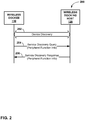
- FIG. 2 is a communication diagram illustrating an example procedure 200 for a communication flow between wireless dockee 110 and wireless docking center 120 to exchange initial wireless communications with each other prior to establishing a wireless docking session with each other, in accordance with some examples of this disclosure.
- the procedure 200 for discovery and initial communication provides for wireless dockee 110 to query wireless docking center 120 for what peripheral functions wireless docking center 120 has access to and might make accessible to wireless dockee 110, from among the peripherals coupled to wireless docking center 120.
- This procedure 200 may be referred to as Peripheral Function Discovery.
- wireless docking center 120 and wireless dockee 110 may initially exchange device discovery communications (202).
- Wireless dockee 110 may send a service discovery query to query wireless docking center 120 for peripheral function information (204), or information on peripheral functions available to wireless docking center 120.
- Applicable peripheral functions may be available to wireless docking center 120 from any of one or more peripheral devices coupled to wireless docking center 120, as described above with peripheral devices 140, 142, 144 in the context of FIG. 1 .
- Wireless docking center 120 serving as a wireless docking host, may send a service discovery response that provides its peripheral function information (206).
- Wireless docking center 120 may thereby advertise its peripheral functions in pre-association service discovery communications (204, 206) with wireless dockee 110.
- These communications are pre-association in that they take place prior to initiation of a wireless docking session between wireless dockee 110 and wireless docking center 120.
- Wireless dockee 110 may thus discover the peripheral functions associated with wireless docking center 120 from the service discovery response 206 as part of the pre-association service discovery communications shown in FIG. 2 . Additional details of these pre-association service discovery communications 204, 206 are provided below.
- the device discovery communications 202 and the service discovery communications 204, 206 as shown in FIG. 2 may be implemented in Data Link Layer, or layer 2 (L2), communications.
- L2 communications may be conveyed over any of various types of physical layer (PHY) communication channels, including any of the Wi-Fi or WiGig standards and/or IEEE 802.11 protocols as discussed above.
- the service discovery query 204 sent by wireless dockee 110 and the service discovery response 206 sent by wireless docking center 120 may use service discovery action frames.
- An example action frame may include a Media Access Control (MAC) header, a frame category, action details, and a frame check sequence (FCS).
- the action details in the service discovery query 204 sent by wireless dockee 110 may include object identifier (OI) fields and query data fields.
- OI object identifier
- Wireless dockee 110 may set an OI field in the service discovery action frame to 0x506F9A, i.e., the Organizationally Unique Identifier (OUI) of the Wi-Fi Alliance (WFA). Wireless dockee 110 may also set additional fields in the service discovery action frame, such as an OUI subtype field and a service protocol type field. Wireless dockee 110 may set the query data field of the service discovery query action frame to include a list of docking sub-element identifiers (ID's) to query for information on available docking sub-elements.
- ID's docking sub-element identifiers
- wireless dockee 100 may communicate with wireless docking center 120 using plaintext payloads that include SOAP requests and responses (e.g., in accordance with the SOAP specification defined at www.w3.org/TR/soap12-part1) and GENA (General Event Notification Architecture) notifications running on a packet-based transport layer protocol stack, while in other examples, wireless dockee 100 may communicate with wireless docking center 120 using a binary protocol running on a packet-based transport layer protocol stack, as further described below.
- Wireless dockee 110 may also set a service transaction identifier (ID) in the query data field. Examples of the query data fields and the docking sub-element ID's for examples using SOAP and GENA payloads are shown as follows in Tables 1 and 2.
- Table 1 Query Data Fields Field Length (Octets) Description List of Docking Sub-element IDs Variable Requested Docking sub-elements as an array of sub-element IDs as per Table 2.
- Table 2 Docking Sub-element IDs Docking Sub-element ID Description ⁇ ⁇ 7
- wireless dockee 100 may communicate with wireless docking center 120 without requiring the use of docking sub-element ID's 8 and 9 as listed in Table 2.
- Wireless docking center 120 may respond to receiving service discovery query 204 from wireless dockee 110 by sending service discovery response 206.
- Wireless docking center 120 may include in service discovery response 206 a service discovery action frame with a service response data field that includes a list of requested docking sub-elements.
- Wireless docking center 120 may include a service transaction ID in the service response type-length-value (TLV) element that matches the service transaction ID in the query data field of the service discovery query 204 from wireless dockee 110, to ensure that wireless dockee 110 can associate the service discovery response 206 with the service discovery query 204.
- Wireless docking center 120 may set a docking information element (IE) in Docking Service Discovery action frames included in the service discovery response 206.
- IE docking information element
- wireless docking center 120 may set the docking IE to include sub-elements as shown as follows in Table 3.
- Table 3 Information Sub-elements in Docking IE in Docking Service Discovery Response Sub-element Name Requirements ⁇ ⁇
- Peripheral Function Information If requested, the Peripheral Function Information sub-element may be present in the Docking IE in the Docking Service Discovery Response action frames that docking host 120 transmits.
- Docking Host SOAP URL If requested, the Docking Host SOAP URL sub-element may be present in the Docking IE in the Docking Service Discovery Response action frames that docking host 120 transmits.
- Docking Host GENA URL If requested, the Docking Host SOAP URL sub-element may be present in the Docking IE in the Docking Service Discovery Response action frames that docking host 120 transmits.
- wireless docking center 120 may omit the docking host SOAP URL and docking host GENA URL from the information sub-elements from the docking information element in the docking service discovery response.
- wireless dockee 110 and wireless docking center 120 may both send SOAP requests and responses to each other, and wireless docking center 120 may send GENA notifications to wireless dockee 110, where both the SOAP and GENA payloads may be sent over a packet-based transport layer protocol stack, in accordance with specifications such as Transmission Control Protocol / Internet Protocol (TCP/IP) or User Datagram Protocol / IP (UDP/IP), for example, to specified URLs, and potentially also to specified port numbers, such as TCP port number 80 (commonly associated with HTTP).
- TCP/IP Transmission Control Protocol / Internet Protocol
- UDP/IP User Datagram Protocol / IP
- the Peripheral Function Information sub-element may provide the peripheral function (PF) information of peripherals hosted by wireless docking center 120.
- the Peripheral Function Information sub-element may have a data structure as shown in Table 4, with additional information on the listed fields thereafter.
- n_PFs may contain the number of peripheral functions (PF's) hosted by wireless docking center 120 that generate this PF Status information data structure. Any one or more peripheral device coupled to wireless docking center 120 (e.g., peripheral devices 140, 142, 144 of FIG. 1 ) may provide one or more peripheral functions.
- peripheral devices 140, 142, 144 of FIG. 1 may provide one or more peripheral functions.
- the field "PF_ID” may contain the ID of a particular peripheral function (PF).
- the peripheral function information sub-element may include a peripheral function ID and associated information for each peripheral function ID for each of the "n_PFs" peripheral functions.
- the peripheral function ID may be unique for all peripheral functions that wireless docking center 120 currently hosts or centers or has ever hosted or centered. Wireless docking center 120 may specify when a peripheral function is new and when the peripheral function is not new (e.g., when a mouse that provides a mouse peripheral function has been replaced by another mouse that may provide a mouse peripheral function).
- PF_type may indicate the peripheral function type of the peripheral function.
- An illustrative set of peripheral function types is listed below in Table 5.
- PF_name may contain a user-friendly name of the peripheral function.
- This peripheral function name may be unique for all PFs available to wireless docking center 120.
- the format of the peripheral function name may be a UTF-8_String() structure, in some examples.
- PF_capability may contain the capability of the peripheral function as reported by wireless docking center 120.
- the format of the peripheral function capability may also be a UTF-8_String() structure, in some examples.
- n_PFPs may contain the number of Peripheral Function Protocols that can be used to support the use of the particular peripheral referred to by a given PF_ID.
- PFP_ID may contain the identifier (ID) of the Peripheral Function Protocol that can be used to support the use of the particular peripheral.
- An illustrative set of peripheral function protocols is listed below in Table 6.
- PF_state may contain the state of the peripheral function, such as with the example states defined below in Table 7.
- Table 5 Peripheral Function Type PF Type Description 0 Mouse 1 Keyboard 2 Remote Control 3 Display 4 Speaker 5 Microphone 6 Storage 7 Joystick 8-65535 Reserved Table 6: Peripheral Function Protocol Identifier PFP ID Description 0 Miracast 1 WiFi Serial Bus (WSB) 2 Bluetooth 3 WiGig Display Extension (WDE) 4 WiGig Serial Extension (WSE) 5-255 Reserved Table 7: PF_state values State Value Description DISCONNECTED 0x01 The PF cannot be reached by its managing wireless docking center (WDH, e.g., docking center 120) and its managing WDH has no further information on how to make it available for docking.
- WDH wireless docking center
- SLEEP 0x02 The PF has let its managing WDH known that it is going to low-power mode or to be switched-off and that user action on the PF is required to make the PF available for docking again. On the other hand, if a PF can be woken up without requiring user action (e.g. through Wake-on-LAN or by changing the USB power state), the PF may not be given the PF_state "SLEEP". Such PFs may be given the state "NOT PAIRED" or "AVAILABLE". NOT_PAIRED 0x03 The only thing that needs to be done for making this PF available for docking is that a user action is needed for pairing the PF with its managing WDH. AVAILABLE 0x04 The PF is available for docking. NOT_AVAILABLE 0x05 The PF is not available for docking.
- the Docking Host SOAP URL sub-element provides the URL of the SOAP command service for the docking protocol provided by wireless docking center 120.
- the Docking Host SOAP URL sub-element may have the data structure shown as follows in Table 8. Table 8: Docking Host SOAP URL Sub-element Field Length (Octets) Type Description port_num 2 uimsbf Port number URL_path Variable UTF-8_String() Substring of URL path, percent-encoded as per Internet Engineering Task Force (IETF) Request for Comment (RFC) 3986
- the Docking Host GENA URL sub-element provides the URL of the GENA notification service for the docking protocol provided by wireless docking center 120.
- the Docking Host GENA URL sub-element may have the data structure shown as follows in Table 9.
- Table 9 Docking Host GENA URL Sub-element Field Length (Octets) Type Description port_num 2 uimsbf Port number URL_path Variable UTF-8_String() Substring of URL path, percent-encoded as per IETF RFC 3986
- wireless dockee (WD) 110 and wireless docking center (WDC) 120 may also be configured to undock with each other.
- the undocking process of this disclosure may be predicated on a determined distance between WD 110 and WDC 120 (i.e., whether or not the WD 110 is still within the vicinity of WDC 120).
- a WD 110 is "out of the vicinity" of a WDC 120 when the WD 110 is physically away from the peripherals connected through the WDC 120 to an extent that it is unlikely that the user of the WD 110 is still in control of or using the peripherals.
- an operation whether in WD 110, WDC 120, or both
- vicinity-based undocking an operation that performs an undocking process based on this "out of the vicinity" condition.
- This disclosure describes two general techniques of vicinity-based undocking.
- One technique is WD centric (i.e., performed almost completely by the WD 110), and the other technique is WDC assisted (i.e., performed through operations by WDC 120 or both WD 110 and WDC 120).
- FIG. 3 is a block diagram showing an example wireless dockee and wireless docking center configured to implement the techniques of this disclosure.
- WD 110 is configured to determine on its own when to undock from WDC 120 due to a determination that WD 110 is out of the vicinity of WDC 120.
- no messaging between WD 110 and WDC 120 is required.
- WD 110 makes a determination to undock based on a measured signal strength between WD 110 and WDC 120 (e.g., the strength of the signal on wireless communication channel 130 of FIG. 1 ).
- WD 110 may include a wireless communication unit 112, a signal strength measuring unit 114, and an undocking determination unit 116.
- Wireless communication unit 112 may comprise one or more processors and a transceiver configured to communicate with WDC 120, for example, using any of the above communication techniques described above with reference to FIG. 1 .
- WD 110 may further include a signal strength measuring unit 114 that may be configured to measure a received signal strength indication (RSSI) for the communication protocol used to communicate with WDC 120 over communication channel 130 (e.g., through wireless communication unit 112).
- RSSI received signal strength indication
- Signal strength measuring may be implemented as one or more processors, or any other hardware capable of measuring the strength of a signal received by wireless communication unit 112 from WDC 120.
- signal strength measuring unit 114 may be configured to measure the RSSI of the received signal.
- RSSI is a measurement of power in a received radio signal.
- a first threshold value i.e., a lower threshold value
- undocking determination unit 116 of WD 110 is configured to start an undocking timer to prepare for undocking.
- Undocking determination unit 116 may be implemented through one or more processors and/or dedicate hardware.
- signal strength measuring unit 114 of WD 110 measures an RSSI at a value higher than a second threshold (i.e., a higher threshold value), before the timer expires, undocking determination unit 116 cancels the undocking procedure, stops the timer, and WD 110 remains docked with WDC 120.
- a second threshold i.e., a higher threshold value
- the difference between the first, lower threshold value and the second, higher threshold value serves as a hysteresis to prevent the ping-pong effect. That is, if only one threshold value for RSSI were used to stop and start the undocking timer, it is possible that the RSSI may fluctuate across this threshold many times, causing frequent starting and stopping of undocking timers.
- undocking determination unit 116 undocks WD 110 from WDC 120.
- WD 110 is no longer able to use any peripheral devices available through WDC 120.
- WD 110 would need to re-dock to WDC 120 (e.g., using the techniques described above with reference to FIG. 2 ) to again use any peripheral devices available through WDC 120.
- WDC 120 peripheral devices available through WDC 120 would not be able to interact with WD 110.
- WD 110 may not be capable of WD-centric vicinity-based undocking (e.g., if WD 110 is not configured to measure an RSSI).
- the disclosure proposes an additional/optional procedure performed by WDC 120 to assist in vicinity-based undocking. This technique of the disclosure may be called WDC-assisted vicinity-based undocking.
- WDC 120 is configured to measure the RSSI of the communication signal between WD 110 and WDC 120.
- WDC 120 may include a wireless communication unit 122, a signal strength measuring unit 124, and an undocking determination unit 126.
- Wireless communication unit 122 may comprise one or more processors and a transceiver configured to communicate with WD 110, for example, using any of the above communication techniques described above with reference to FIG. 1 .
- WDC 120 may further include a signal strength measuring unit 124 that may be configured to measure a received signal strength indication (RSSI) for the communication protocol used to communicate with WD 110 over communication channel 130 (e.g., through wireless communication unit 122).
- RSSI received signal strength indication
- Signal strength measuring may be implemented as one or more processors, or any other hardware capable of measuring the strength of a signal received by wireless communication unit 122 from WD 110.
- undocking determination unit 126 is configured to send a message (e.g., through wireless communication unit 122) to inform WD 110 that an undocking procedure is beginning and undocking determination unit 126 starts an undocking timer to prepare for undocking.
- WD 110 may display this message to a user to inform the user of the pending undocking, thus allowing the user to move to a closer vicinity to prevent undocking.
- Undocking determination unit 126 may be implemented through one or more processors and/or dedicated hardware. If the timer expires, undocking determination unit 126 undocks WD 110.
- undocking determination unit 126 cancels the undocking timer. Again, the difference between the lower value and the higher value serves as hysteresis to prevent the ping pong effect.
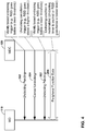
- FIG. 4 shows an example call flow for a WDC-assisted vicinity-based undocking procedure.
- peripheral function data 206 is communicated between WD 110 and WDC 120.
- Peripheral function data 206 may be any data, syntax, handshaking, etc., which may be used by WD 110 and peripheral devices available through WDC 120.
- undocking pending message 202 may be signaled from WDC 120 to WD 110 based on a signal strength trigger (e.g., WDC 120 measure an RSSI below a lower threshold).
- WDC 120 is configured to start an undocking timer based on the measured RSSI below the lower threshold. If WDC 120 detects an RSSI above a higher threshold, cancel undocking message 204 is sent to WD 110 and the undocking timer is stopped.
- a new undocking pending message 202 may be sent to WD 110 if a measured RSSI subsequently goes below the lower threshold, and the undocking timer may be restarted. If the undocking timer expires, WDC 120 undocks from WD 110 and peripheral function data 206 communication ceases.
- Both WDC 120 and WD 110 may use a Normalized RSSI (NRSSI) to estimate whether or not WD 110 is within the vicinity of WDC 120.
- NRSSI is defined as the currently detected RSSI divided by a reference RSSI.
- the reference RSSI value may be selected based on 1) the maximum working distance for an active docking session expected by user and 2) the RSSI detected in field tests for such maximum distance.
- the NRSSI Threshold Upper, NRSSI_TU may be set at 0.6 and the NRSSI Threshold Lower, NRSSI_TL may be set at 0.5. Regardless of actual value, the upper threshold is set to be greater than the lower threshold, i.e., set NRSSI_TU > NRSSI_TL.
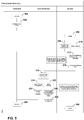
- FIG. 5 is an example state machine showing an example WDC-assisted vicinity-based undocking procedure in more detail.
- the left column of FIG. 5 represents the states of a wireless docking environment (i.e., WD 110 and WDC 120), when WD 110 and WDC 120 are undocked.
- the center column shows the states when undocking is pending.
- the right column shows the states when WD 110 and WDC 120 are docked.
- WD 110 and WDC 120 are in undocked state 302. Docking may be accomplished through docking session setup 304, for example, using the techniques described above with reference to FIG. 2 . However, any techniques for establishing docking may be used. Once docked, WD 110 and WDC 120 are in docked state 306, thus allowing WD 110 to interact with and use peripheral devices 140, 142, and 144 available through WDC 120. WD 110 and WDC 120 remain in docked state 306 until undocking is triggered. In one example, conventional undocking triggers may be used, such as docking session teardown or connection error 308. Docking session teardown may be a manual undocking request by WD 110. Connection error may occur when communication is lost between WD 110 and WDC 120. Should docking session teardown or connection error 308 occur, WD 110 and WDC 120 return to undocked state 302.
- another trigger for undocking WD 110 and WDC 120 may involve measuring a signal strength (e.g., NRSSI) of the communication between WD 110 and WDC 120.
- WDC 120 measures that NRSSI is below a lower threshold (NRSSI_TL).
- NRSSI_TL a lower threshold
- WDC 120 sends an undocking pending notification message 312 to WD 110.
- WD 110 may display this message to a user to inform the user of the pending undocking, thus allowing the user to move to a closer vicinity to prevent undocking.
- WDC 120 After sending notification 312, WDC 120 starts an undocking pending timer 314 and WD 110 and WDC 120 move to an undocking pending state 316. If the undocking pending timer expires (state 318), WD 110 and WDC 120 move to docking session teardown state 322, and eventually, undocked state 302. However, if WDC 120 measures that the NRSSI moves above a higher threshold (NRSSI_TU) 320, WDC 120 may send a docking resume notification message 324 to WD 110. WD 110 may display this message to a user of WD 110 to inform the user that docking may continue. Such a message may also be used to remove the undocking pending message 312. WDC 120 then cancels the undocking pending timer 326 and WD 110 and WDC 120 return to docked state 306.
- NRSSI_TU a higher threshold
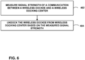
- FIG. 6 is a flowchart showing an example method according to the techniques of the disclosure. The method of FIG. 4 may be carried out by either WD 110 or WDC 120.
- a method for vicinity-based undocking in a wireless docking environment comprises measuring a signal strength of a communication between a wireless dockee and a wireless docking center (402), and undocking the wireless dockee from the wireless docking center based on the measured signal strength (404).
- the measured signal strength is a normalized received signal strength indication (NRSSI).
- either WD 110 or WDC 120 may be configured to undock the wireless dockee from the wireless docking center based on the measured signal strength using the following steps.
- WD 110 or WDC 120 starts a timer if the measured signal strength is below a lower threshold.
- WD 110 or WDC 120 continues measuring the signal strength of the communication between the wireless dockee and the wireless docking center.
- WD 110 or WDC 120 stops the timer in the case that the measured signal strength is above a higher threshold, whereby the wireless dockee and the wireless docking center remain docked, and wherein the higher threshold has a higher value that the lower threshold.
- WD 110 or WDC 120 undocks the wireless dockee from the wireless docking center in the case that the timer expires.
- WDC 120 may be configured to undock the wireless dockee from the wireless docking center based on the measured signal strength using the following steps.
- WDC 120 starts a timer if the measured signal strength is below a lower threshold.
- WDC 120 sends a message from WDC 120 to the wireless dockee indicating that undocking is pending.
- WDC 120 continues measuring the signal strength of the communication between the wireless dockee and WDC 120.
- WDC 120 stops the timer in the case that the measured signal strength is above a higher threshold, whereby the wireless dockee and WDC 120 remain docked, and wherein the higher threshold has a higher value that the lower threshold.
- WDC 120 undocks the wireless dockee from WDC 120 in the case that the timer expires.
- Computer-readable media may include computer-readable storage media, which corresponds to a tangible medium such as data storage media, or communication media including any medium that facilitates transfer of a computer program from one place to another, e.g., according to a communication protocol.
- Computer-readable media generally may correspond to (1) tangible computer-readable storage media which is non-transitory or (2) a communication medium such as a signal or carrier wave.
- Data storage media may be any available media that can be accessed by one or more computers or one or more processors to retrieve instructions, code and/or data structures for implementation of the techniques described in this disclosure.
- a computer program product may include a computer-readable medium.
- such computer-readable storage media can comprise RAM, ROM, EEPROM, CD-ROM or other optical disk storage, magnetic disk storage, or other magnetic storage devices, flash memory, or any other medium that can be used to store desired program code in the form of instructions or data structures and that can be accessed by a computer.
- any connection is properly termed a computer-readable medium.
- a computer-readable medium For example, if instructions are transmitted from a website, server, or other remote source using a coaxial cable, fiber optic cable, twisted pair, digital subscriber line (DSL), or wireless technologies such as infrared, radio, and microwave, then the coaxial cable, fiber optic cable, twisted pair, DSL, or wireless technologies such as infrared, radio, and microwave are included in the definition of medium.
- DSL digital subscriber line
- Disk and disc includes compact disc (CD), laser disc, optical disc, digital versatile disc (DVD), floppy disk and Blu-ray disc, where disks usually reproduce data magnetically, while discs reproduce data optically with lasers. Combinations of the above should also be included within the scope of computer-readable media.
- processors such as one or more digital signal processors (DSPs), general purpose microprocessors, application specific integrated circuits (ASICs), field programmable logic arrays (FPGAs), or other equivalent integrated or discrete logic circuitry.
- DSPs digital signal processors
- ASICs application specific integrated circuits
- FPGAs field programmable logic arrays
- processors may refer to any of the foregoing structure or any other structure suitable for implementation of the techniques described herein.
- the functionality described herein may be provided within dedicated hardware and/or software modules configured for encoding and decoding, or incorporated in a combined codec. Also, the techniques could be fully implemented in one or more circuits or logic elements.
- the techniques of this disclosure may be implemented in a wide variety of devices or apparatuses, including a wireless handset, an integrated circuit (IC) or a set of ICs (e.g., a chip set).
- IC integrated circuit
- a set of ICs e.g., a chip set.
- Various components, modules, or units are described in this disclosure to emphasize functional aspects of devices configured to perform the disclosed techniques, but do not necessarily require realization by different hardware units. Rather, as described above, various units may be combined in a codec hardware unit or provided by a collection of interoperative hardware units, including one or more processors as described above, in conjunction with suitable software and/or firmware.
Description
- This application claims the benefit of
U.S. Provisional Application No. 61/835,370, filed June 14, 2013 - This disclosure relates to techniques for wireless docking between electronic devices.
- Docking stations, which may also be referred to as "docks," are sometimes used to couple electronic devices such as laptop computers to peripherals such as monitors, keyboards, mice, printers, or other types of input or output devices. These docking stations typically require a physical connection between the electronic device and the docking station. Additionally, the electronic device and the docking station typically establish docking communications before docking functions may be used.
- Attention is drawn to the document
WO 2013/076625 A1 describing a method and system for achieving configurability and controllability over the initiation of automatic docking for a portable device seeking to dock wirelessly with a docking station in a wireless docking system environment. The portable device detects the docking station in the wireless docking environment. When the docking station is detected, a communication path is established between the portable device and the docking station. A received signal characteristic level is measured for a received signal. The received signal characteristic level is compared to a determined threshold so that, at least when the received signal level exceeds the determined threshold, docking the portable device to the docking station is able to be completed. The determined threshold is based on signal measurements made for the received signal characteristic level which exceeds a minimum signal strength level required for establishing communication between the portable device and the docking station - Also attention is drawn to the Document
US 8 254 992 B1 . Here a wireless docking system and method is provided for monitoring the use of one or more docking stations by multiple portable computers The system and method provides for management of docking stations and connected resources by implementing a protocol that takes into account the identity of the user insofar as one user my have priority to the use of a docking station the length of time an inactive computer has been connected to a docking station whether another user requests the use of the docking station, whether the strength of the communication signals between a wireless docking station and computer is adequate to support the use of the docking station, and whether a user wishes to terminate a connection with a docking station. - In accordance with the present invention, a method and apparatus, as set forth in the independent claims, is provided. Embodiments of the invention are claimed in the dependent claims.
- This disclosure describes wireless communication techniques, protocols, methods, and devices applicable to a docking system environment in which aspects of wireless docking may function using vicinity-based undocking techniques. In some example, this disclosure proposes techniques whereby a wireless dockee or a wireless docking center may implement an undocking procedure based on a detected vicinity of the wireless dockee, for example, using a measured signal strength of a communication between the wireless dockee and the wireless docking center.
- In one example, this disclosure describes a method for vicinity-based undocking in a wireless docking environment comprising measuring a signal strength of a communication between a wireless dockee and a wireless docking center, and undocking the wireless dockee from the wireless docking center based on the measured signal strength.
- In another example, this disclosure describes a wireless dockee configured to perform vicinity-based undocking in a wireless docking environment, the wireless dockee comprising a wireless communication unit configured to communicate with a wireless docking center, a signal strength measuring unit configured to measure a signal strength of the communication between the wireless dockee and the wireless docking center, and an undocking determination unit configured to undock the wireless dockee from the wireless docking center based on the measured signal strength.
- In another example, this disclosure describes a wireless docking center configured to perform vicinity-based undocking in a wireless docking environment, the wireless docking center comprising a wireless communication unit configured to communicate with a wireless dockee, a signal strength measuring unit configured to measure a signal strength of the communication between the wireless dockee and the wireless docking center, and an undocking determination unit configured to undock the wireless dockee from the wireless docking center based on the measured signal strength.
- In another example, this disclosure describes an apparatus configured to perform vicinity-based undocking in a wireless docking environment, the apparatus comprising means for measuring a signal strength of a communication between a wireless dockee and a wireless docking center, and means for undocking the wireless dockee from the wireless docking center based on the measured signal strength.
- In another example, this disclosure describes a computer-readable storage medium storing instructions that, when executed, cause one or more processors of a device configured to perform vicinity-based undocking to measure a signal strength of a communication between a wireless dockee and a wireless docking center, and undock the wireless dockee from the wireless docking center based on the measured signal strength.
- The details of one or more examples are set forth in the accompanying drawings and the description below. Other features, objects, and advantages will be apparent from the description and drawings, and from the claims.
-
-
FIG. 1 is a conceptual diagram illustrating an example wireless docking environment in which a wireless dockee communicates with a wireless docking center over a wireless communication channel in accordance with examples of this disclosure. -
FIG. 2 is a communication diagram illustrating an example procedure for a communication flow between a dockee and a docking center to exchange initial wireless communications with each other prior to establishing a wireless docking session with each other, in accordance with some examples of this disclosure. -
FIG. 3 is a block diagram showing an example wireless dockee and wireless docking center configured to implement the techniques of this disclosure. -
FIG. 4 shows an example call flow for a wireless docking center assisted vicinity-based undocking procedure according to the techniques of this disclosure. -
FIG. 5 is an example state machine showing an example wireless docking center assisted vicinity-based undocking procedure according to the techniques of the disclosure. -
FIG. 6 is a flowchart illustrating an example method in accordance with examples of this disclosure. - As described in greater detail below, this disclosure describes wireless communication techniques, protocols, methods, and devices applicable to a docking system environment in which aspects of wireless docking may function using vicinity-based undocking techniques. In some examples, the techniques of this disclosure enable a wireless docking center to undock a wireless dockee in a situation where a wireless dockee moves out of the vicinity of a wireless docking center so as to prevent malicious users from using peripheral devices available through the wireless docking center to interact with the wireless dockee without the wireless dockee user's knowledge. In other examples, the wireless dockee may undock itself from a wireless docking center when the wireless dockee moves out of the vicinity of a wireless docking center.
-
FIG. 1 is a conceptual diagram of an examplewireless docking environment 100 in whichwireless dockee 110 communicates with awireless docking center 120 overwireless communication channel 130.Wireless dockee 110 may be a mobile device configured for wireless docking and referred to as a wireless dockee in the context of awireless docking environment 100. Wireless dockee 110 may be a mobile device such as a smartphone or other mobile handset, a tablet computer, a laptop computer, or any other electronic device capable of communicating wirelessly with WDC 120.Wireless dockee 110 may also be a component of a larger device or system. For example,wireless dockee 110 may be a processor, a processing core, a chipset, or one or more integrated circuits. - Wireless docking center 120 (which may also be referred to as a wireless docking station or wireless docking hub) may be communicatively coupled with various
peripheral devices wireless docking center 120 may advertise and/or make accessible towireless dockee 110.Wireless docking center 120 may be a wireless docking host device that serves as a connectivity agent within a computing environment.Wireless docking center 120 may be a dedicated wireless dock, or may also be implemented in a smartphone or other mobile handset, a tablet computer, a laptop computer, desktop computer, or other electronic device, or as a component, subsystem, or one or more integrated circuits included as part of a larger device or system of any of the above. -
Peripheral devices wireless docking center 120.Peripheral devices wireless docking center 120 via wired or wireless communication channels.Wireless docking center 120 may abstract the functions of individualperipheral devices -
Wireless communication channel 130 may be any channel capable of propagating communicative signals betweenwireless dockee 110 andwireless docking center 120. In some examples,wireless communication channel 130 may be implemented in radio frequency communications in frequency bands, such as the 2.4 gigahertz (GHz) band, the 5 GHz band, the 60 GHz band, or other frequency bands. In some examples,wireless communication channel 130 may comply with one or more sets of standards, protocols, or technologies, including, for example, Wi-Fi (as promoted by the Wi-Fi Alliance), WiGig (as promoted by the Wireless Gigabit Alliance), and/or the Institute of Electrical and Electronics Engineers (IEEE) 802.11 set of standards (e.g., 802.11, 802.11 a, 802.11b, 802.11g, 802.11n, 802.11ac, 802.11ad, etc.), or other standards, protocols, or technologies. The frequency bands used forwireless communication channel 130, such as the 2.4 GHz, 5 GHz, and 60 GHz bands, may be defined for purposes of this disclosure as they are understood in light of the standards of Wi-Fi, WiGig, any one or more IEEE 802.11 protocols, and/or other applicable standards or protocols. In some examples,wireless dockee 110 may establish communication withwireless docking center 120 overwireless communication channel 130 automatically oncewireless dockee 110 andwireless docking center 120 come within operative communication range of each other, or manually in response to a user input, in different examples. - As will be explained in more detail below, one or more of
wireless dockee 110 andwireless docking center 120 may be configured to undock with each other using the techniques of this disclosure. The undocking process of this disclosure may be predicated on a distance betweenwireless dockee 110 and wireless docking center 120 (i.e., whether or notwireless dockee 110 is still within the vicinity of wireless docking center 120). -
FIG. 2 is a communication diagram illustrating anexample procedure 200 for a communication flow betweenwireless dockee 110 andwireless docking center 120 to exchange initial wireless communications with each other prior to establishing a wireless docking session with each other, in accordance with some examples of this disclosure. Theprocedure 200 for discovery and initial communication provides forwireless dockee 110 to querywireless docking center 120 for what peripheral functionswireless docking center 120 has access to and might make accessible towireless dockee 110, from among the peripherals coupled towireless docking center 120. Thisprocedure 200 may be referred to as Peripheral Function Discovery. - As shown in the communication flow in
FIG. 2 ,wireless docking center 120 andwireless dockee 110 may initially exchange device discovery communications (202).Wireless dockee 110 may send a service discovery query to querywireless docking center 120 for peripheral function information (204), or information on peripheral functions available towireless docking center 120. Applicable peripheral functions may be available towireless docking center 120 from any of one or more peripheral devices coupled towireless docking center 120, as described above withperipheral devices FIG. 1 .Wireless docking center 120, serving as a wireless docking host, may send a service discovery response that provides its peripheral function information (206).Wireless docking center 120 may thereby advertise its peripheral functions in pre-association service discovery communications (204, 206) withwireless dockee 110. These communications are pre-association in that they take place prior to initiation of a wireless docking session betweenwireless dockee 110 andwireless docking center 120.Wireless dockee 110 may thus discover the peripheral functions associated withwireless docking center 120 from theservice discovery response 206 as part of the pre-association service discovery communications shown inFIG. 2 . Additional details of these pre-associationservice discovery communications - The
device discovery communications 202 and theservice discovery communications FIG. 2 may be implemented in Data Link Layer, or layer 2 (L2), communications. The L2 communications may be conveyed over any of various types of physical layer (PHY) communication channels, including any of the Wi-Fi or WiGig standards and/or IEEE 802.11 protocols as discussed above. Theservice discovery query 204 sent by wireless dockee 110 and theservice discovery response 206 sent bywireless docking center 120 may use service discovery action frames. An example action frame may include a Media Access Control (MAC) header, a frame category, action details, and a frame check sequence (FCS). The action details in theservice discovery query 204 sent bywireless dockee 110 may include object identifier (OI) fields and query data fields.Wireless dockee 110 may set an OI field in the service discovery action frame to 0x506F9A, i.e., the Organizationally Unique Identifier (OUI) of the Wi-Fi Alliance (WFA).Wireless dockee 110 may also set additional fields in the service discovery action frame, such as an OUI subtype field and a service protocol type field.Wireless dockee 110 may set the query data field of the service discovery query action frame to include a list of docking sub-element identifiers (ID's) to query for information on available docking sub-elements. In some examples,wireless dockee 100 may communicate withwireless docking center 120 using plaintext payloads that include SOAP requests and responses (e.g., in accordance with the SOAP specification defined at www.w3.org/TR/soap12-part1) and GENA (General Event Notification Architecture) notifications running on a packet-based transport layer protocol stack, while in other examples,wireless dockee 100 may communicate withwireless docking center 120 using a binary protocol running on a packet-based transport layer protocol stack, as further described below.Wireless dockee 110 may also set a service transaction identifier (ID) in the query data field. Examples of the query data fields and the docking sub-element ID's for examples using SOAP and GENA payloads are shown as follows in Tables 1 and 2.Table 1: Query Data Fields Field Length (Octets) Description List of Docking Sub-element IDs Variable Requested Docking sub-elements as an array of sub-element IDs as per Table 2. Table 2: Docking Sub-element IDs Docking Sub-element ID Description ··· ··· 7 Peripheral Function Information 8 Docking Host SOAP URL 9 Docking Host GENA URL 10-255 Reserved - In some examples that may use a binary protocol instead of SOAP and GENA payloads,
wireless dockee 100 may communicate withwireless docking center 120 without requiring the use of docking sub-element ID's 8 and 9 as listed in Table 2. -
Wireless docking center 120 may respond to receivingservice discovery query 204 fromwireless dockee 110 by sendingservice discovery response 206.Wireless docking center 120 may include in service discovery response 206 a service discovery action frame with a service response data field that includes a list of requested docking sub-elements.Wireless docking center 120 may include a service transaction ID in the service response type-length-value (TLV) element that matches the service transaction ID in the query data field of theservice discovery query 204 fromwireless dockee 110, to ensure thatwireless dockee 110 can associate theservice discovery response 206 with theservice discovery query 204.Wireless docking center 120 may set a docking information element (IE) in Docking Service Discovery action frames included in theservice discovery response 206. In some examples,wireless docking center 120 may set the docking IE to include sub-elements as shown as follows in Table 3.Table 3: Information Sub-elements in Docking IE in Docking Service Discovery Response Sub-element Name Requirements ··· ··· Peripheral Function Information If requested, the Peripheral Function Information sub-element may be present in the Docking IE in the Docking Service Discovery Response action frames that docking host 120 transmits.Docking Host SOAP URL If requested, the Docking Host SOAP URL sub-element may be present in the Docking IE in the Docking Service Discovery Response action frames that docking host 120 transmits.Docking Host GENA URL If requested, the Docking Host SOAP URL sub-element may be present in the Docking IE in the Docking Service Discovery Response action frames that docking host 120 transmits.··· ··· - These docking information sub-elements provided by the
wireless docking center 120 inservice discovery response 206, i.e., the Peripheral Function Information Sub-element, the Docking Host SOAP Uniform Resource Locator (URL) Sub-element, and the Docking Host General Event Notification Architecture (GENA) URL Sub-element, are further described as follows. In examples that use a binary protocol,wireless docking center 120 may omit the docking host SOAP URL and docking host GENA URL from the information sub-elements from the docking information element in the docking service discovery response. In some examples that use the SOAP and GENA payloads,wireless dockee 110 andwireless docking center 120 may both send SOAP requests and responses to each other, andwireless docking center 120 may send GENA notifications towireless dockee 110, where both the SOAP and GENA payloads may be sent over a packet-based transport layer protocol stack, in accordance with specifications such as Transmission Control Protocol / Internet Protocol (TCP/IP) or User Datagram Protocol / IP (UDP/IP), for example, to specified URLs, and potentially also to specified port numbers, such as TCP port number 80 (commonly associated with HTTP). - The Peripheral Function Information sub-element may provide the peripheral function (PF) information of peripherals hosted by
wireless docking center 120. The Peripheral Function Information sub-element may have a data structure as shown in Table 4, with additional information on the listed fields thereafter.Table 4: Peripheral Function Information Sub-element Field Length (Octets) Type n_PFs 1 uimsbf for (i = 0; i < n_PFs; i++) { PF_ID 2 uimsbf PF_type 2 uimsbf PF_name Variable UTF-8_String() PF_capability Variable UTF-8_String() PF_state 1 uimsbf n_PFPs 1 uimsbf for (i = 0; I < n_PFPs; i++) { PFP_ID 1 uimsbf } } - The field "n_PFs" may contain the number of peripheral functions (PF's) hosted by
wireless docking center 120 that generate this PF Status information data structure. Any one or more peripheral device coupled to wireless docking center 120 (e.g.,peripheral devices FIG. 1 ) may provide one or more peripheral functions. - The field "PF_ID" may contain the ID of a particular peripheral function (PF). As indicated by the line "for (i = 0; i < n_PFs; i++)," the peripheral function information sub-element may include a peripheral function ID and associated information for each peripheral function ID for each of the "n_PFs" peripheral functions. The peripheral function ID may be unique for all peripheral functions that
wireless docking center 120 currently hosts or centers or has ever hosted or centered.Wireless docking center 120 may specify when a peripheral function is new and when the peripheral function is not new (e.g., when a mouse that provides a mouse peripheral function has been replaced by another mouse that may provide a mouse peripheral function). - The field "PF_type" may indicate the peripheral function type of the peripheral function. An illustrative set of peripheral function types is listed below in Table 5.
- The field "PF_name" may contain a user-friendly name of the peripheral function. This peripheral function name may be unique for all PFs available to
wireless docking center 120. The format of the peripheral function name may be a UTF-8_String() structure, in some examples. - The field "PF_capability" may contain the capability of the peripheral function as reported by
wireless docking center 120. The format of the peripheral function capability may also be a UTF-8_String() structure, in some examples. - The field "n_PFPs" may contain the number of Peripheral Function Protocols that can be used to support the use of the particular peripheral referred to by a given PF_ID. The field "PFP_ID" may contain the identifier (ID) of the Peripheral Function Protocol that can be used to support the use of the particular peripheral. An illustrative set of peripheral function protocols is listed below in Table 6. The field "PF_state" may contain the state of the peripheral function, such as with the example states defined below in Table 7.
Table 5: Peripheral Function Type PF Type Description 0 Mouse 1 Keyboard 2 Remote Control 3 Display 4 Speaker 5 Microphone 6 Storage 7 Joystick 8-65535 Reserved Table 6: Peripheral Function Protocol Identifier PFP ID Description 0 Miracast 1 WiFi Serial Bus (WSB) 2 Bluetooth 3 WiGig Display Extension (WDE) 4 WiGig Serial Extension (WSE) 5-255 Reserved Table 7: PF_state values State Value Description DISCONNECTED 0x01 The PF cannot be reached by its managing wireless docking center (WDH, e.g., docking center 120) and its managing WDH has no further information on how to make it available for docking. SLEEP 0x02 The PF has let its managing WDH known that it is going to low-power mode or to be switched-off and that user action on the PF is required to make the PF available for docking again. On the other hand, if a PF can be woken up without requiring user action (e.g. through Wake-on-LAN or by changing the USB power state), the PF may not be given the PF_state "SLEEP". Such PFs may be given the state "NOT PAIRED" or "AVAILABLE". NOT_PAIRED 0x03 The only thing that needs to be done for making this PF available for docking is that a user action is needed for pairing the PF with its managing WDH. AVAILABLE 0x04 The PF is available for docking. NOT_AVAILABLE 0x05 The PF is not available for docking. - The Docking Host SOAP URL sub-element provides the URL of the SOAP command service for the docking protocol provided by
wireless docking center 120. The Docking Host SOAP URL sub-element may have the data structure shown as follows in Table 8.Table 8: Docking Host SOAP URL Sub-element Field Length (Octets) Type Description port_num 2 uimsbf Port number URL_path Variable UTF-8_String() Substring of URL path, percent-encoded as per Internet Engineering Task Force (IETF) Request for Comment (RFC) 3986 - The Docking Host GENA URL sub-element provides the URL of the GENA notification service for the docking protocol provided by
wireless docking center 120. The Docking Host GENA URL sub-element may have the data structure shown as follows in Table 9.Table 9: Docking Host GENA URL Sub-element Field Length (Octets) Type Description port_num 2 uimsbf Port number URL_path Variable UTF-8_String() Substring of URL path, percent-encoded as per IETF RFC 3986 - In accordance with the techniques of this disclosure, wireless dockee (WD) 110 and wireless docking center (WDC) 120 may also be configured to undock with each other. The undocking process of this disclosure may be predicated on a determined distance between
WD 110 and WDC 120 (i.e., whether or not theWD 110 is still within the vicinity of WDC 120). - In the context of this disclosure, a
WD 110 is "out of the vicinity" of aWDC 120 when theWD 110 is physically away from the peripherals connected through theWDC 120 to an extent that it is unlikely that the user of theWD 110 is still in control of or using the peripherals. As such, also in the context of this disclosure, an operation (whether inWD 110,WDC 120, or both) that performs an undocking process based on this "out of the vicinity" condition is referred to as vicinity-based undocking. - This disclosure describes two general techniques of vicinity-based undocking. One technique is WD centric (i.e., performed almost completely by the WD 110), and the other technique is WDC assisted (i.e., performed through operations by
WDC 120 or bothWD 110 and WDC 120). -
FIG. 3 is a block diagram showing an example wireless dockee and wireless docking center configured to implement the techniques of this disclosure. For the WD-centric vicinity-based undocking,WD 110 is configured to determine on its own when to undock fromWDC 120 due to a determination thatWD 110 is out of the vicinity ofWDC 120. In one example WD-centric vicinity-based undocking technique, no messaging betweenWD 110 andWDC 120 is required. Instead,WD 110 makes a determination to undock based on a measured signal strength betweenWD 110 and WDC 120 (e.g., the strength of the signal onwireless communication channel 130 ofFIG. 1 ). - In one example,
WD 110 may include a wireless communication unit 112, a signalstrength measuring unit 114, and anundocking determination unit 116. Wireless communication unit 112 may comprise one or more processors and a transceiver configured to communicate withWDC 120, for example, using any of the above communication techniques described above with reference toFIG. 1 .WD 110 may further include a signalstrength measuring unit 114 that may be configured to measure a received signal strength indication (RSSI) for the communication protocol used to communicate withWDC 120 over communication channel 130 (e.g., through wireless communication unit 112). Signal strength measuring may be implemented as one or more processors, or any other hardware capable of measuring the strength of a signal received by wireless communication unit 112 fromWDC 120. - As discussed above, in on example, signal
strength measuring unit 114 may be configured to measure the RSSI of the received signal. RSSI is a measurement of power in a received radio signal. When the measured RSSI drops below a first threshold value (i.e., a lower threshold value), undockingdetermination unit 116 ofWD 110 is configured to start an undocking timer to prepare for undocking.Undocking determination unit 116 may be implemented through one or more processors and/or dedicate hardware. If signalstrength measuring unit 114 ofWD 110 measures an RSSI at a value higher than a second threshold (i.e., a higher threshold value), before the timer expires, undockingdetermination unit 116 cancels the undocking procedure, stops the timer, andWD 110 remains docked withWDC 120. The difference between the first, lower threshold value and the second, higher threshold value serves as a hysteresis to prevent the ping-pong effect. That is, if only one threshold value for RSSI were used to stop and start the undocking timer, it is possible that the RSSI may fluctuate across this threshold many times, causing frequent starting and stopping of undocking timers. By providing a gap between the lower threshold (to start the undocking timer) and the higher threshold (to stop the undocking timer), such a ping-pong effect is mitigated. If the timer expires before the occurrence of any RSSI measurement above the higher threshold value, undockingdetermination unit 116undocks WD 110 fromWDC 120. - Once undocked from
WDC 120,WD 110 is no longer able to use any peripheral devices available throughWDC 120.WD 110 would need to re-dock to WDC 120 (e.g., using the techniques described above with reference toFIG. 2 ) to again use any peripheral devices available throughWDC 120. Likewise, onceWD 110 is undocked fromWDC 120, peripheral devices available throughWDC 120 would not be able to interact withWD 110. Thus, preventing a malicious user from interacting withWD 110 through a peripheral device without the knowledge of the user ofWD 110. - In some circumstances,
WD 110 may not be capable of WD-centric vicinity-based undocking (e.g., ifWD 110 is not configured to measure an RSSI). In this example, the disclosure proposes an additional/optional procedure performed byWDC 120 to assist in vicinity-based undocking. This technique of the disclosure may be called WDC-assisted vicinity-based undocking. In this example,WDC 120 is configured to measure the RSSI of the communication signal betweenWD 110 andWDC 120. - Referring back to
FIG. 3 ,WDC 120 may include awireless communication unit 122, a signalstrength measuring unit 124, and an undocking determination unit 126.Wireless communication unit 122 may comprise one or more processors and a transceiver configured to communicate withWD 110, for example, using any of the above communication techniques described above with reference toFIG. 1 .WDC 120 may further include a signalstrength measuring unit 124 that may be configured to measure a received signal strength indication (RSSI) for the communication protocol used to communicate withWD 110 over communication channel 130 (e.g., through wireless communication unit 122). Signal strength measuring may be implemented as one or more processors, or any other hardware capable of measuring the strength of a signal received bywireless communication unit 122 fromWD 110. - In the example of WDC-assisted vicinity-based undocking, when signal
strength measuring unit 124 ofWDC 120 measures that the RSSI has dropped below a lower threshold value, undocking determination unit 126 is configured to send a message (e.g., through wireless communication unit 122) to informWD 110 that an undocking procedure is beginning and undocking determination unit 126 starts an undocking timer to prepare for undocking.WD 110 may display this message to a user to inform the user of the pending undocking, thus allowing the user to move to a closer vicinity to prevent undocking. Undocking determination unit 126 may be implemented through one or more processors and/or dedicated hardware. If the timer expires, undocking determination unit 126undocks WD 110. If signalstrength measuring unit 124 measures an RSSI at a value above a higher threshold value, undocking determination unit 126 cancels the undocking timer. Again, the difference between the lower value and the higher value serves as hysteresis to prevent the ping pong effect. -
FIG. 4 shows an example call flow for a WDC-assisted vicinity-based undocking procedure. As shown inFIG. 4 , while docked,peripheral function data 206 is communicated betweenWD 110 andWDC 120.Peripheral function data 206 may be any data, syntax, handshaking, etc., which may be used byWD 110 and peripheral devices available throughWDC 120. - In WDC-assisted vicinity-based undocking, undocking pending
message 202 may be signaled fromWDC 120 toWD 110 based on a signal strength trigger (e.g.,WDC 120 measure an RSSI below a lower threshold).WDC 120 is configured to start an undocking timer based on the measured RSSI below the lower threshold. IfWDC 120 detects an RSSI above a higher threshold, cancel undockingmessage 204 is sent toWD 110 and the undocking timer is stopped. A newundocking pending message 202 may be sent toWD 110 if a measured RSSI subsequently goes below the lower threshold, and the undocking timer may be restarted. If the undocking timer expires,WDC 120 undocks fromWD 110 andperipheral function data 206 communication ceases. - Both
WDC 120 andWD 110 may use a Normalized RSSI (NRSSI) to estimate whether or notWD 110 is within the vicinity ofWDC 120. The NRSSI is defined as the currently detected RSSI divided by a reference RSSI. The reference RSSI value may be selected based on 1) the maximum working distance for an active docking session expected by user and 2) the RSSI detected in field tests for such maximum distance. - In one example, the NRSSI Threshold Upper, NRSSI_TU may be set at 0.6 and the NRSSI Threshold Lower, NRSSI_TL may be set at 0.5. Regardless of actual value, the upper threshold is set to be greater than the lower threshold, i.e., set NRSSI_TU > NRSSI_TL.
-
FIG. 5 is an example state machine showing an example WDC-assisted vicinity-based undocking procedure in more detail. The left column ofFIG. 5 represents the states of a wireless docking environment (i.e.,WD 110 and WDC 120), whenWD 110 andWDC 120 are undocked. The center column shows the states when undocking is pending. The right column shows the states whenWD 110 andWDC 120 are docked. - Initially,
WD 110 andWDC 120 are in undockedstate 302. Docking may be accomplished throughdocking session setup 304, for example, using the techniques described above with reference toFIG. 2 . However, any techniques for establishing docking may be used. Once docked,WD 110 andWDC 120 are in dockedstate 306, thus allowingWD 110 to interact with and useperipheral devices WDC 120.WD 110 andWDC 120 remain in dockedstate 306 until undocking is triggered. In one example, conventional undocking triggers may be used, such as docking session teardown orconnection error 308. Docking session teardown may be a manual undocking request byWD 110. Connection error may occur when communication is lost betweenWD 110 andWDC 120. Should docking session teardown orconnection error 308 occur,WD 110 andWDC 120 return to undockedstate 302. - Based on the techniques of this disclosure, another trigger for undocking
WD 110 andWDC 120 may involve measuring a signal strength (e.g., NRSSI) of the communication betweenWD 110 andWDC 120. Instate 310,WDC 120 measures that NRSSI is below a lower threshold (NRSSI_TL). In other examples, as described above,WD 110 may be configured to measure the signal strength. Based on the measurement of the NRSSI below the lower threshold,WDC 120 sends an undocking pendingnotification message 312 toWD 110.WD 110 may display this message to a user to inform the user of the pending undocking, thus allowing the user to move to a closer vicinity to prevent undocking. - After sending
notification 312,WDC 120 starts anundocking pending timer 314 andWD 110 andWDC 120 move to anundocking pending state 316. If the undocking pending timer expires (state 318),WD 110 andWDC 120 move to dockingsession teardown state 322, and eventually, undockedstate 302. However, ifWDC 120 measures that the NRSSI moves above a higher threshold (NRSSI_TU) 320,WDC 120 may send a dockingresume notification message 324 toWD 110.WD 110 may display this message to a user ofWD 110 to inform the user that docking may continue. Such a message may also be used to remove theundocking pending message 312.WDC 120 then cancels theundocking pending timer 326 andWD 110 andWDC 120 return to dockedstate 306. -
FIG. 6 is a flowchart showing an example method according to the techniques of the disclosure. The method ofFIG. 4 may be carried out by eitherWD 110 orWDC 120. - In one example of the disclosure, a method for vicinity-based undocking in a wireless docking environment comprises measuring a signal strength of a communication between a wireless dockee and a wireless docking center (402), and undocking the wireless dockee from the wireless docking center based on the measured signal strength (404). In one example, the measured signal strength is a normalized received signal strength indication (NRSSI).
- In one example, either
WD 110 orWDC 120 may be configured to undock the wireless dockee from the wireless docking center based on the measured signal strength using the following steps.WD 110 orWDC 120 starts a timer if the measured signal strength is below a lower threshold.WD 110 orWDC 120 continues measuring the signal strength of the communication between the wireless dockee and the wireless docking center.WD 110 orWDC 120 stops the timer in the case that the measured signal strength is above a higher threshold, whereby the wireless dockee and the wireless docking center remain docked, and wherein the higher threshold has a higher value that the lower threshold.WD 110 orWDC 120 undocks the wireless dockee from the wireless docking center in the case that the timer expires. - In another example,
WDC 120 may be configured to undock the wireless dockee from the wireless docking center based on the measured signal strength using the following steps.WDC 120 starts a timer if the measured signal strength is below a lower threshold.WDC 120 sends a message fromWDC 120 to the wireless dockee indicating that undocking is pending.WDC 120 continues measuring the signal strength of the communication between the wireless dockee andWDC 120.WDC 120 stops the timer in the case that the measured signal strength is above a higher threshold, whereby the wireless dockee andWDC 120 remain docked, and wherein the higher threshold has a higher value that the lower threshold.WDC 120 undocks the wireless dockee fromWDC 120 in the case that the timer expires. - It is to be recognized that depending on the example, certain acts or events of any of the techniques described herein can be performed in a different sequence, may be added, merged, or left out altogether (e.g., not all described acts or events are necessary for the practice of the techniques). Moreover, in certain examples, acts or events may be performed concurrently, e.g., through multi-threaded processing, interrupt processing, or multiple processors, rather than sequentially.
- In one or more examples, the functions described may be implemented in hardware, software, firmware, or any combination thereof. If implemented in software, the functions may be stored on or transmitted over as one or more instructions or code on a computer-readable medium and executed by a hardware-based processing unit. Computer-readable media may include computer-readable storage media, which corresponds to a tangible medium such as data storage media, or communication media including any medium that facilitates transfer of a computer program from one place to another, e.g., according to a communication protocol. In this manner, computer-readable media generally may correspond to (1) tangible computer-readable storage media which is non-transitory or (2) a communication medium such as a signal or carrier wave. Data storage media may be any available media that can be accessed by one or more computers or one or more processors to retrieve instructions, code and/or data structures for implementation of the techniques described in this disclosure. A computer program product may include a computer-readable medium.
- By way of example, and not limitation, such computer-readable storage media can comprise RAM, ROM, EEPROM, CD-ROM or other optical disk storage, magnetic disk storage, or other magnetic storage devices, flash memory, or any other medium that can be used to store desired program code in the form of instructions or data structures and that can be accessed by a computer. Also, any connection is properly termed a computer-readable medium. For example, if instructions are transmitted from a website, server, or other remote source using a coaxial cable, fiber optic cable, twisted pair, digital subscriber line (DSL), or wireless technologies such as infrared, radio, and microwave, then the coaxial cable, fiber optic cable, twisted pair, DSL, or wireless technologies such as infrared, radio, and microwave are included in the definition of medium. It should be understood, however, that computer-readable storage media and data storage media do not include connections, carrier waves, signals, or other transitory media, but are instead directed to non-transitory, tangible storage media. Disk and disc, as used herein, includes compact disc (CD), laser disc, optical disc, digital versatile disc (DVD), floppy disk and Blu-ray disc, where disks usually reproduce data magnetically, while discs reproduce data optically with lasers. Combinations of the above should also be included within the scope of computer-readable media.
- Instructions may be executed by one or more processors, such as one or more digital signal processors (DSPs), general purpose microprocessors, application specific integrated circuits (ASICs), field programmable logic arrays (FPGAs), or other equivalent integrated or discrete logic circuitry. Accordingly, the term "processor," as used herein may refer to any of the foregoing structure or any other structure suitable for implementation of the techniques described herein. In addition, in some aspects, the functionality described herein may be provided within dedicated hardware and/or software modules configured for encoding and decoding, or incorporated in a combined codec. Also, the techniques could be fully implemented in one or more circuits or logic elements.
- The techniques of this disclosure may be implemented in a wide variety of devices or apparatuses, including a wireless handset, an integrated circuit (IC) or a set of ICs (e.g., a chip set). Various components, modules, or units are described in this disclosure to emphasize functional aspects of devices configured to perform the disclosed techniques, but do not necessarily require realization by different hardware units. Rather, as described above, various units may be combined in a codec hardware unit or provided by a collection of interoperative hardware units, including one or more processors as described above, in conjunction with suitable software and/or firmware.
- Various examples have been described. These and other examples are within the scope of the following claims.
Claims (11)
- A method for vicinity-based undocking in a wireless docking environment, the method comprising:measuring (402) a signal strength of a communication between a wireless dockee (110) and a wireless docking center (120);starting (314) a timer if the measured signal strength is below a lower threshold;continuing measuring the signal strength of the communication between the wireless dockee and the wireless docking center;stopping (326) the timer in the case that the measured signal strength is above a higher threshold, whereby the wireless dockee and the wireless docking center remain docked, and wherein the higher threshold has a higher value than the lower threshold; andundocking (322, 404) the wireless dockee from the wireless docking center in the case that the timer expires.
- The method of claim 1, wherein the measured signal strength is a normalized received signal strength indication, NRSSI.
- The method of claim 1, further comprising:sending a message (202) from the wireless docking center (120) to the wireless dockee (110) indicating that undocking is pending in response to the measured signal strength being below the lower threshold.
- The method of any of claims 1, 2, or 3, wherein the method is performed by the wireless docking center (120).
- The method of any of claims 1 or 2, wherein the method is performed by the wireless dockee (110).
- An apparatus (110, 120) configured to perform vicinity-based undocking in a wireless docking environment, the apparatus comprising:means for measuring (114, 124) a signal strength of a communication between a wireless dockee (110) and a wireless docking center (120); andmeans for undocking (116, 126) the wireless dockee from the wireless docking center based on the measured signal strength, wherein the means for undocking the wireless dockee from the wireless docking center based on the measured signal strength comprises:means for starting a timer if the measured signal strength is below a lower threshold;means for continuing measuring the signal strength of the communication between the wireless dockee and the wireless docking center;means for stopping the timer in the case that the measured signal strength is above a higher threshold, whereby the wireless dockee and the wireless docking center remain docked, and wherein the higher threshold has a higher value than the lower threshold; andmeans for undocking the wireless dockee from the wireless docking center in the case that the timer expires.
- The apparatus (110, 120) of claim 6, wherein the measured signal strength is a normalized received signal strength indication, NRSSI.
- The apparatus (110, 120) of claim 6, wherein the means for undocking the wireless dockee from the wireless docking center based on the measured signal strength comprises:means for sending a message (202) from the wireless docking center to the wireless dockee indicating that undocking is pending in response to the measured signal strength being below the lower threshold.
- The apparatus (110, 120) of any of claims 6, 7, or 8, wherein the apparatus is the wireless docking center (120).
- The apparatus (110, 120) of any of claims 6 or 7, wherein the apparatus is the wireless dockee (110).
- A computer-readable storage medium storing instructions that, when executed, cause one or more processors of a device configured to perform the steps of any of claims 1 to 5.
Applications Claiming Priority (3)
| Application Number | Priority Date | Filing Date | Title |
|---|---|---|---|
| US201361835370P | 2013-06-14 | 2013-06-14 | |
| US14/206,953 US9634757B2 (en) | 2013-06-14 | 2014-03-12 | Vicinity-based undocking for a wireless docking application |
| PCT/US2014/039408 WO2014200687A1 (en) | 2013-06-14 | 2014-05-23 | Vicinity-based undocking for a wireless docking application |
Publications (2)
| Publication Number | Publication Date |
|---|---|
| EP3008882A1 EP3008882A1 (en) | 2016-04-20 |
| EP3008882B1 true EP3008882B1 (en) | 2017-04-05 |
Family
ID=52019627
Family Applications (1)
| Application Number | Title | Priority Date | Filing Date |
|---|---|---|---|
| EP14733819.8A Not-in-force EP3008882B1 (en) | 2013-06-14 | 2014-05-23 | Vicinity-based undocking for a wireless docking application |
Country Status (6)
| Country | Link |
|---|---|
| US (1) | US9634757B2 (en) |
| EP (1) | EP3008882B1 (en) |
| JP (1) | JP6235131B2 (en) |
| KR (1) | KR101827991B1 (en) |
| CN (1) | CN105324980B (en) |
| WO (1) | WO2014200687A1 (en) |
Families Citing this family (13)
| Publication number | Priority date | Publication date | Assignee | Title |
|---|---|---|---|---|
| JP2015019196A (en) * | 2013-07-10 | 2015-01-29 | 船井電機株式会社 | Server device, client device, and content reproduction program |
| TWI648630B (en) * | 2014-03-31 | 2019-01-21 | 荷蘭商皇家飛利浦有限公司 | Wireless communication system |
| US20160112982A1 (en) * | 2014-06-30 | 2016-04-21 | Michael Babineau | System and method for the retention of universal serial bus and wireless communiction enabled devices |
| US10104699B2 (en) * | 2015-02-10 | 2018-10-16 | Sphero, Inc. | Signal strength representation and automatic connection and control upon a self-propelled device |
| US9497790B2 (en) * | 2015-03-03 | 2016-11-15 | Google Inc. | Simulation of near-field communications |
| JP6152242B2 (en) * | 2015-04-06 | 2017-06-21 | レノボ・シンガポール・プライベート・リミテッド | Method for ensuring information security of portable electronic device, portable electronic device and function expansion device |
| KR20170090598A (en) * | 2016-01-29 | 2017-08-08 | 삼성전자주식회사 | Method and System for Providing Hotel Services |
| US10248584B2 (en) | 2016-04-01 | 2019-04-02 | Microsoft Technology Licensing, Llc | Data transfer between host and peripheral devices |
| US11647463B2 (en) | 2017-09-13 | 2023-05-09 | Intel Corporation | Methods and arrangements to enable wake-up receiver for modes of operation |
| US11576123B2 (en) | 2017-10-11 | 2023-02-07 | Intel Corporation | Methods and arrangements to support wake-up radio packet transmission |
| US11589309B2 (en) | 2018-01-12 | 2023-02-21 | Intel Corporation | Methods and arrangements to support wake-up radio packet transmission |
| KR102466837B1 (en) | 2018-08-03 | 2022-11-16 | 삼성전자주식회사 | An electronic device and Method for controlling the electronic device thereof |
| US11341075B2 (en) * | 2020-08-12 | 2022-05-24 | Dell Products L.P. | Method for selectively connecting to a smart peripheral and system therefor |
Family Cites Families (12)
| Publication number | Priority date | Publication date | Assignee | Title |
|---|---|---|---|---|
| JP2000163171A (en) * | 1998-11-24 | 2000-06-16 | Sharp Corp | Communication control method between portable terminal and docking station and portable terminal mountable on docking station |
| JP2002016539A (en) * | 2000-06-28 | 2002-01-18 | Toshiba Corp | Electronic device with wireless communication fault detecting function and system |
| JP2003229812A (en) * | 2002-02-06 | 2003-08-15 | Matsushita Electric Ind Co Ltd | Electronic equipment |
| US8750248B2 (en) * | 2007-03-21 | 2014-06-10 | Qualcomm Incorporated | Methods and apparatus for RF handoff in a multi-frequency network |
| US8254992B1 (en) | 2007-10-08 | 2012-08-28 | Motion Computing, Inc. | Wireless docking system and pairing protocol for multiple dock environments |
| US7978632B2 (en) * | 2008-05-13 | 2011-07-12 | Nortel Networks Limited | Wireless mesh network transit link topology optimization method and system |
| US20120317489A1 (en) * | 2010-02-09 | 2012-12-13 | Nokia Corporation | Method and Apparatus Providing for Transmission of a Content Package |
| JP5117539B2 (en) * | 2010-06-14 | 2013-01-16 | 日本電信電話株式会社 | HANDOVER METHOD AND RADIO COMMUNICATION DEVICE |
| US8462734B2 (en) * | 2010-10-20 | 2013-06-11 | Nokia Corporation | Wireless docking with out-of-band initiation |
| JP5468595B2 (en) * | 2011-11-22 | 2014-04-09 | レノボ・シンガポール・プライベート・リミテッド | Method of accessing wireless network by shared communication and wireless terminal device |
| MY168255A (en) * | 2011-11-23 | 2018-10-16 | Koninklijke Philips Nv | Method and apparatus for configuration and control of wireless docking |
| CN102970733B (en) * | 2012-12-06 | 2016-05-04 | 惠州Tcl移动通信有限公司 | Mobile terminal and wireless connection method thereof |
-
2014
- 2014-03-12 US US14/206,953 patent/US9634757B2/en not_active Expired - Fee Related
- 2014-05-23 KR KR1020167000015A patent/KR101827991B1/en active IP Right Grant
- 2014-05-23 EP EP14733819.8A patent/EP3008882B1/en not_active Not-in-force
- 2014-05-23 WO PCT/US2014/039408 patent/WO2014200687A1/en active Application Filing
- 2014-05-23 CN CN201480033383.0A patent/CN105324980B/en not_active Expired - Fee Related
- 2014-05-23 JP JP2016519520A patent/JP6235131B2/en not_active Expired - Fee Related
Non-Patent Citations (1)
| Title |
|---|
| None * |
Also Published As
| Publication number | Publication date |
|---|---|
| CN105324980A (en) | 2016-02-10 |
| US20140370810A1 (en) | 2014-12-18 |
| EP3008882A1 (en) | 2016-04-20 |
| JP6235131B2 (en) | 2017-11-22 |
| US9634757B2 (en) | 2017-04-25 |
| KR101827991B1 (en) | 2018-02-13 |
| KR20160021179A (en) | 2016-02-24 |
| CN105324980B (en) | 2018-05-11 |
| WO2014200687A1 (en) | 2014-12-18 |
| JP2016531461A (en) | 2016-10-06 |
Similar Documents
| Publication | Publication Date | Title |
|---|---|---|
| EP3008882B1 (en) | Vicinity-based undocking for a wireless docking application | |
| KR101876533B1 (en) | Dockee-centric wireless docking | |
| EP2946299B1 (en) | Wireless docking service with direct connection to peripherals | |
| US9832596B2 (en) | Wireless docking architecture | |
| US9811116B2 (en) | Utilization and configuration of wireless docking environments | |
| KR101830876B1 (en) | Supporting unrecognized peripheral function protocol in a wireless docking station | |
| WO2014189660A1 (en) | Access control for wireless docking | |
| US9451551B2 (en) | Controlling a power state of a cellular packet data subsystem in a portable electronic device | |
| EP3577952A1 (en) | Method and system for selection of an access and mobility management function in an access network environment | |
| WO2019073091A1 (en) | Handling of parameters provided in release / suspend | |
| EP3130160B1 (en) | Wireless docking/undocking using fine time measurement | |
| JP6321817B2 (en) | Vendor specific docking management behavior | |
| WO2020020058A1 (en) | Measurement method, terminal and network side device | |
| WO2018153194A1 (en) | Streaming data acquisition method, device, and system | |
| WO2023193677A1 (en) | Measurement processing method and apparatus, and terminal and network-side device | |
| OA20212A (en) | Handling of parameters provided in release / suspend. |
Legal Events
| Date | Code | Title | Description |
|---|---|---|---|
| PUAI | Public reference made under article 153(3) epc to a published international application that has entered the european phase |
Free format text: ORIGINAL CODE: 0009012 |
|
| 17P | Request for examination filed |
Effective date: 20151102 |
|
| AK | Designated contracting states |
Kind code of ref document: A1 Designated state(s): AL AT BE BG CH CY CZ DE DK EE ES FI FR GB GR HR HU IE IS IT LI LT LU LV MC MK MT NL NO PL PT RO RS SE SI SK SM TR |
|
| AX | Request for extension of the european patent |
Extension state: BA ME |
|
| DAX | Request for extension of the european patent (deleted) | ||
| GRAP | Despatch of communication of intention to grant a patent |
Free format text: ORIGINAL CODE: EPIDOSNIGR1 |
|
| INTG | Intention to grant announced |
Effective date: 20161019 |
|
| GRAS | Grant fee paid |
Free format text: ORIGINAL CODE: EPIDOSNIGR3 |
|
| GRAA | (expected) grant |
Free format text: ORIGINAL CODE: 0009210 |
|
| REG | Reference to a national code |
Ref country code: FR Ref legal event code: PLFP Year of fee payment: 4 |
|
| AK | Designated contracting states |
Kind code of ref document: B1 Designated state(s): AL AT BE BG CH CY CZ DE DK EE ES FI FR GB GR HR HU IE IS IT LI LT LU LV MC MK MT NL NO PL PT RO RS SE SI SK SM TR |
|
| REG | Reference to a national code |
Ref country code: GB Ref legal event code: FG4D |
|
| REG | Reference to a national code |
Ref country code: CH Ref legal event code: EP |
|
| REG | Reference to a national code |
Ref country code: AT Ref legal event code: REF Ref document number: 882784 Country of ref document: AT Kind code of ref document: T Effective date: 20170415 |
|
| REG | Reference to a national code |
Ref country code: IE Ref legal event code: FG4D |
|
| REG | Reference to a national code |
Ref country code: DE Ref legal event code: R096 Ref document number: 602014008381 Country of ref document: DE |
|
| REG | Reference to a national code |
Ref country code: NL Ref legal event code: MP Effective date: 20170405 |
|
| REG | Reference to a national code |
Ref country code: LT Ref legal event code: MG4D |
|
| REG | Reference to a national code |
Ref country code: AT Ref legal event code: MK05 Ref document number: 882784 Country of ref document: AT Kind code of ref document: T Effective date: 20170405 |
|
| PG25 | Lapsed in a contracting state [announced via postgrant information from national office to epo] |
Ref country code: NL Free format text: LAPSE BECAUSE OF FAILURE TO SUBMIT A TRANSLATION OF THE DESCRIPTION OR TO PAY THE FEE WITHIN THE PRESCRIBED TIME-LIMIT Effective date: 20170405 |
|
| PG25 | Lapsed in a contracting state [announced via postgrant information from national office to epo] |
Ref country code: HR Free format text: LAPSE BECAUSE OF FAILURE TO SUBMIT A TRANSLATION OF THE DESCRIPTION OR TO PAY THE FEE WITHIN THE PRESCRIBED TIME-LIMIT Effective date: 20170405 Ref country code: GR Free format text: LAPSE BECAUSE OF FAILURE TO SUBMIT A TRANSLATION OF THE DESCRIPTION OR TO PAY THE FEE WITHIN THE PRESCRIBED TIME-LIMIT Effective date: 20170706 Ref country code: NO Free format text: LAPSE BECAUSE OF FAILURE TO SUBMIT A TRANSLATION OF THE DESCRIPTION OR TO PAY THE FEE WITHIN THE PRESCRIBED TIME-LIMIT Effective date: 20170705 Ref country code: AT Free format text: LAPSE BECAUSE OF FAILURE TO SUBMIT A TRANSLATION OF THE DESCRIPTION OR TO PAY THE FEE WITHIN THE PRESCRIBED TIME-LIMIT Effective date: 20170405 Ref country code: LT Free format text: LAPSE BECAUSE OF FAILURE TO SUBMIT A TRANSLATION OF THE DESCRIPTION OR TO PAY THE FEE WITHIN THE PRESCRIBED TIME-LIMIT Effective date: 20170405 Ref country code: ES Free format text: LAPSE BECAUSE OF FAILURE TO SUBMIT A TRANSLATION OF THE DESCRIPTION OR TO PAY THE FEE WITHIN THE PRESCRIBED TIME-LIMIT Effective date: 20170405 Ref country code: FI Free format text: LAPSE BECAUSE OF FAILURE TO SUBMIT A TRANSLATION OF THE DESCRIPTION OR TO PAY THE FEE WITHIN THE PRESCRIBED TIME-LIMIT Effective date: 20170405 |
|
| PG25 | Lapsed in a contracting state [announced via postgrant information from national office to epo] |
Ref country code: LV Free format text: LAPSE BECAUSE OF FAILURE TO SUBMIT A TRANSLATION OF THE DESCRIPTION OR TO PAY THE FEE WITHIN THE PRESCRIBED TIME-LIMIT Effective date: 20170405 Ref country code: IS Free format text: LAPSE BECAUSE OF FAILURE TO SUBMIT A TRANSLATION OF THE DESCRIPTION OR TO PAY THE FEE WITHIN THE PRESCRIBED TIME-LIMIT Effective date: 20170805 Ref country code: PL Free format text: LAPSE BECAUSE OF FAILURE TO SUBMIT A TRANSLATION OF THE DESCRIPTION OR TO PAY THE FEE WITHIN THE PRESCRIBED TIME-LIMIT Effective date: 20170405 Ref country code: BG Free format text: LAPSE BECAUSE OF FAILURE TO SUBMIT A TRANSLATION OF THE DESCRIPTION OR TO PAY THE FEE WITHIN THE PRESCRIBED TIME-LIMIT Effective date: 20170705 Ref country code: RS Free format text: LAPSE BECAUSE OF FAILURE TO SUBMIT A TRANSLATION OF THE DESCRIPTION OR TO PAY THE FEE WITHIN THE PRESCRIBED TIME-LIMIT Effective date: 20170405 Ref country code: SE Free format text: LAPSE BECAUSE OF FAILURE TO SUBMIT A TRANSLATION OF THE DESCRIPTION OR TO PAY THE FEE WITHIN THE PRESCRIBED TIME-LIMIT Effective date: 20170405 |
|
| REG | Reference to a national code |
Ref country code: CH Ref legal event code: PL |
|
| REG | Reference to a national code |
Ref country code: DE Ref legal event code: R097 Ref document number: 602014008381 Country of ref document: DE |
|
| PG25 | Lapsed in a contracting state [announced via postgrant information from national office to epo] |
Ref country code: RO Free format text: LAPSE BECAUSE OF FAILURE TO SUBMIT A TRANSLATION OF THE DESCRIPTION OR TO PAY THE FEE WITHIN THE PRESCRIBED TIME-LIMIT Effective date: 20170405 Ref country code: CZ Free format text: LAPSE BECAUSE OF FAILURE TO SUBMIT A TRANSLATION OF THE DESCRIPTION OR TO PAY THE FEE WITHIN THE PRESCRIBED TIME-LIMIT Effective date: 20170405 Ref country code: SK Free format text: LAPSE BECAUSE OF FAILURE TO SUBMIT A TRANSLATION OF THE DESCRIPTION OR TO PAY THE FEE WITHIN THE PRESCRIBED TIME-LIMIT Effective date: 20170405 Ref country code: MC Free format text: LAPSE BECAUSE OF FAILURE TO SUBMIT A TRANSLATION OF THE DESCRIPTION OR TO PAY THE FEE WITHIN THE PRESCRIBED TIME-LIMIT Effective date: 20170405 Ref country code: DK Free format text: LAPSE BECAUSE OF FAILURE TO SUBMIT A TRANSLATION OF THE DESCRIPTION OR TO PAY THE FEE WITHIN THE PRESCRIBED TIME-LIMIT Effective date: 20170405 Ref country code: EE Free format text: LAPSE BECAUSE OF FAILURE TO SUBMIT A TRANSLATION OF THE DESCRIPTION OR TO PAY THE FEE WITHIN THE PRESCRIBED TIME-LIMIT Effective date: 20170405 |
|
| PLBE | No opposition filed within time limit |
Free format text: ORIGINAL CODE: 0009261 |
|
| STAA | Information on the status of an ep patent application or granted ep patent |
Free format text: STATUS: NO OPPOSITION FILED WITHIN TIME LIMIT |
|
| REG | Reference to a national code |
Ref country code: IE Ref legal event code: MM4A |
|
| PG25 | Lapsed in a contracting state [announced via postgrant information from national office to epo] |
Ref country code: IT Free format text: LAPSE BECAUSE OF FAILURE TO SUBMIT A TRANSLATION OF THE DESCRIPTION OR TO PAY THE FEE WITHIN THE PRESCRIBED TIME-LIMIT Effective date: 20170405 Ref country code: LI Free format text: LAPSE BECAUSE OF NON-PAYMENT OF DUE FEES Effective date: 20170531 Ref country code: SM Free format text: LAPSE BECAUSE OF FAILURE TO SUBMIT A TRANSLATION OF THE DESCRIPTION OR TO PAY THE FEE WITHIN THE PRESCRIBED TIME-LIMIT Effective date: 20170405 Ref country code: CH Free format text: LAPSE BECAUSE OF NON-PAYMENT OF DUE FEES Effective date: 20170531 |
|
| 26N | No opposition filed |
Effective date: 20180108 |
|
| PG25 | Lapsed in a contracting state [announced via postgrant information from national office to epo] |
Ref country code: LU Free format text: LAPSE BECAUSE OF NON-PAYMENT OF DUE FEES Effective date: 20170523 |
|
| REG | Reference to a national code |
Ref country code: FR Ref legal event code: PLFP Year of fee payment: 5 |
|
| REG | Reference to a national code |
Ref country code: BE Ref legal event code: MM Effective date: 20170531 |
|
| PG25 | Lapsed in a contracting state [announced via postgrant information from national office to epo] |
Ref country code: IE Free format text: LAPSE BECAUSE OF NON-PAYMENT OF DUE FEES Effective date: 20170523 |
|
| PGFP | Annual fee paid to national office [announced via postgrant information from national office to epo] |
Ref country code: GB Payment date: 20180328 Year of fee payment: 5 |
|
| PG25 | Lapsed in a contracting state [announced via postgrant information from national office to epo] |
Ref country code: SI Free format text: LAPSE BECAUSE OF FAILURE TO SUBMIT A TRANSLATION OF THE DESCRIPTION OR TO PAY THE FEE WITHIN THE PRESCRIBED TIME-LIMIT Effective date: 20170405 |
|
| PGFP | Annual fee paid to national office [announced via postgrant information from national office to epo] |
Ref country code: DE Payment date: 20180507 Year of fee payment: 5 |
|
| PG25 | Lapsed in a contracting state [announced via postgrant information from national office to epo] |
Ref country code: BE Free format text: LAPSE BECAUSE OF NON-PAYMENT OF DUE FEES Effective date: 20170531 |
|
| PGFP | Annual fee paid to national office [announced via postgrant information from national office to epo] |
Ref country code: FR Payment date: 20180416 Year of fee payment: 5 |
|
| PG25 | Lapsed in a contracting state [announced via postgrant information from national office to epo] |
Ref country code: MT Free format text: LAPSE BECAUSE OF NON-PAYMENT OF DUE FEES Effective date: 20170523 |
|
| PG25 | Lapsed in a contracting state [announced via postgrant information from national office to epo] |
Ref country code: HU Free format text: LAPSE BECAUSE OF FAILURE TO SUBMIT A TRANSLATION OF THE DESCRIPTION OR TO PAY THE FEE WITHIN THE PRESCRIBED TIME-LIMIT; INVALID AB INITIO Effective date: 20140523 |
|
| PG25 | Lapsed in a contracting state [announced via postgrant information from national office to epo] |
Ref country code: CY Free format text: LAPSE BECAUSE OF FAILURE TO SUBMIT A TRANSLATION OF THE DESCRIPTION OR TO PAY THE FEE WITHIN THE PRESCRIBED TIME-LIMIT Effective date: 20170405 |
|
| PG25 | Lapsed in a contracting state [announced via postgrant information from national office to epo] |
Ref country code: MK Free format text: LAPSE BECAUSE OF FAILURE TO SUBMIT A TRANSLATION OF THE DESCRIPTION OR TO PAY THE FEE WITHIN THE PRESCRIBED TIME-LIMIT Effective date: 20170405 |
|
| REG | Reference to a national code |
Ref country code: DE Ref legal event code: R119 Ref document number: 602014008381 Country of ref document: DE |
|
| GBPC | Gb: european patent ceased through non-payment of renewal fee |
Effective date: 20190523 |
|
| PG25 | Lapsed in a contracting state [announced via postgrant information from national office to epo] |
Ref country code: TR Free format text: LAPSE BECAUSE OF FAILURE TO SUBMIT A TRANSLATION OF THE DESCRIPTION OR TO PAY THE FEE WITHIN THE PRESCRIBED TIME-LIMIT Effective date: 20170405 |
|
| PG25 | Lapsed in a contracting state [announced via postgrant information from national office to epo] |
Ref country code: DE Free format text: LAPSE BECAUSE OF NON-PAYMENT OF DUE FEES Effective date: 20191203 Ref country code: GB Free format text: LAPSE BECAUSE OF NON-PAYMENT OF DUE FEES Effective date: 20190523 |
|
| PG25 | Lapsed in a contracting state [announced via postgrant information from national office to epo] |
Ref country code: PT Free format text: LAPSE BECAUSE OF FAILURE TO SUBMIT A TRANSLATION OF THE DESCRIPTION OR TO PAY THE FEE WITHIN THE PRESCRIBED TIME-LIMIT Effective date: 20170405 |
|
| PG25 | Lapsed in a contracting state [announced via postgrant information from national office to epo] |
Ref country code: FR Free format text: LAPSE BECAUSE OF NON-PAYMENT OF DUE FEES Effective date: 20190531 |
|
| PG25 | Lapsed in a contracting state [announced via postgrant information from national office to epo] |
Ref country code: AL Free format text: LAPSE BECAUSE OF FAILURE TO SUBMIT A TRANSLATION OF THE DESCRIPTION OR TO PAY THE FEE WITHIN THE PRESCRIBED TIME-LIMIT Effective date: 20170405 |