EP3007340A1 - Square wave generator to dither carrier frequency in switched dc/dc converter - Google Patents
Square wave generator to dither carrier frequency in switched dc/dc converter Download PDFInfo
- Publication number
- EP3007340A1 EP3007340A1 EP15161464.1A EP15161464A EP3007340A1 EP 3007340 A1 EP3007340 A1 EP 3007340A1 EP 15161464 A EP15161464 A EP 15161464A EP 3007340 A1 EP3007340 A1 EP 3007340A1
- Authority
- EP
- European Patent Office
- Prior art keywords
- triangular wave
- ldc
- analog controller
- period
- component
- Prior art date
- Legal status (The legal status is an assumption and is not a legal conclusion. Google has not performed a legal analysis and makes no representation as to the accuracy of the status listed.)
- Withdrawn
Links
- 239000003990 capacitor Substances 0.000 claims description 4
- 238000010586 diagram Methods 0.000 description 13
- 230000008901 benefit Effects 0.000 description 5
- 230000000694 effects Effects 0.000 description 4
- 239000000446 fuel Substances 0.000 description 4
- 238000000034 method Methods 0.000 description 3
- 238000006243 chemical reaction Methods 0.000 description 1
- 238000002485 combustion reaction Methods 0.000 description 1
- 230000005684 electric field Effects 0.000 description 1
- 239000002803 fossil fuel Substances 0.000 description 1
- 239000003502 gasoline Substances 0.000 description 1
- 239000003208 petroleum Substances 0.000 description 1
Images




Classifications
-
- H—ELECTRICITY
- H02—GENERATION; CONVERSION OR DISTRIBUTION OF ELECTRIC POWER
- H02M—APPARATUS FOR CONVERSION BETWEEN AC AND AC, BETWEEN AC AND DC, OR BETWEEN DC AND DC, AND FOR USE WITH MAINS OR SIMILAR POWER SUPPLY SYSTEMS; CONVERSION OF DC OR AC INPUT POWER INTO SURGE OUTPUT POWER; CONTROL OR REGULATION THEREOF
- H02M1/00—Details of apparatus for conversion
- H02M1/44—Circuits or arrangements for compensating for electromagnetic interference in converters or inverters
-
- H—ELECTRICITY
- H03—ELECTRONIC CIRCUITRY
- H03K—PULSE TECHNIQUE
- H03K3/00—Circuits for generating electric pulses; Monostable, bistable or multistable circuits
- H03K3/01—Details
- H03K3/013—Modifications of generator to prevent operation by noise or interference
-
- H—ELECTRICITY
- H03—ELECTRONIC CIRCUITRY
- H03K—PULSE TECHNIQUE
- H03K4/00—Generating pulses having essentially a finite slope or stepped portions
- H03K4/06—Generating pulses having essentially a finite slope or stepped portions having triangular shape
-
- H—ELECTRICITY
- H03—ELECTRONIC CIRCUITRY
- H03K—PULSE TECHNIQUE
- H03K7/00—Modulating pulses with a continuously-variable modulating signal
- H03K7/08—Duration or width modulation ; Duty cycle modulation
-
- H—ELECTRICITY
- H02—GENERATION; CONVERSION OR DISTRIBUTION OF ELECTRIC POWER
- H02M—APPARATUS FOR CONVERSION BETWEEN AC AND AC, BETWEEN AC AND DC, OR BETWEEN DC AND DC, AND FOR USE WITH MAINS OR SIMILAR POWER SUPPLY SYSTEMS; CONVERSION OF DC OR AC INPUT POWER INTO SURGE OUTPUT POWER; CONTROL OR REGULATION THEREOF
- H02M3/00—Conversion of DC power input into DC power output
Definitions
- the present disclosure relates to an apparatus for generating a switching signal for an analog controller, and more particularly, to an apparatus for generating a switching signal which is used in an analog pulse width modulation controller of a low DC-DC converter (LDC) for a hybrid vehicle or an electric vehicle.
- LDC low DC-DC converter
- a hybrid vehicle refers to a vehicle driven by efficiently combining two different kinds of power sources.
- a hybrid vehicle is typically driven by an engine (i.e., internal combustion engine) obtaining a torque by combusting fuel (i.e., fossil fuel, such as gasoline) and an electric motor obtaining a torque by battery power.
- an engine i.e., internal combustion engine
- fuel i.e., fossil fuel, such as gasoline
- electric motor obtaining a torque by battery power.
- the hybrid vehicle or the electric vehicle is equipped with an auxiliary battery which supplies driving power to electric components of the vehicle along with a main battery which provides driving power of an electric motor (i.e., driving motor), in which the auxiliary battery is connected to a low voltage DC-DC converter (LDC or LVDCDC, hereinafter, referred to as LDC) for output conversion between a high voltage and a low voltage.
- LDC low voltage DC-DC converter
- the LDC in hybrid or electric vehicles is an apparatus serving as an alternator of the vehicle. To this point, the LDC supplies an electric field load of 12 V, converts a high DC voltage from a high voltage battery into a low DC voltage, and charges the converted low DC voltage in the auxiliary battery.
- LDC analog controllers generate a fixed switching frequency (for example, 100 kHz) using values of a resistor RT and a capacitor CT, based on an oscillator equipped therein and control the LDC depending on the generated switching frequency. Therefore, noise is generated due to high speed switching, thereby causing radio frequency interference (RFI). Further, the existing LDC analog controller needs an expensive filter to remove the high-speed switching noise.
- a fixed switching frequency for example, 100 kHz
- An aspect of the present disclosure provides an apparatus for generating a switching signal for an analog controller to allow an analog pulse width modulation (PWM) controller of a low DC-DC converter (LDC) for a hybrid or electric vehicle to have a frequency spreading range corresponding to preset voltages V ref_high and V ref_low and a modulation rate corresponding to a preset period, by generating a triangular wave as a switching signal at the preset voltages
- PWM pulse width modulation
- LDC low DC-DC converter
- V ref_high and V ref_low and the preset period.
- an apparatus for generating a switching signal for an analog controller includes: a voltage setting unit configured to set voltages V ref_high and V ref_low of a triangular wave; a period adjuster configured to adjust a period of the triangular wave; a triangular wave generator configured to generate the triangular wave at the period based on the voltages set by the voltage setting unit; and an AC component passing unit configured to pass an AC component of the triangular wave through a low voltage DC-DC converter (LDC) analog controller.
- LDC low voltage DC-DC converter
- the AC component passing unit may pass through only the AC component of the triangular wave independent of an offset.
- the AC component passing unit may include a capacitor and a resistor.
- the voltages may determine a spreading range of a switching frequency of the LDC analog controller.
- the period may determine a modulation rate of the LDC analog controller.
- vehicle or “vehicular” or other similar term as used herein is inclusive of motor vehicles in general such as passenger automobiles including sports utility vehicles (SUV), buses, trucks, various commercial vehicles, watercraft including a variety of boats and ships, aircraft, and the like, and includes hybrid vehicles, electric vehicles, plug-in hybrid electric vehicles, hydrogen-powered vehicles and other alternative fuel vehicles (e.g., fuels derived from resources other than petroleum).
- a hybrid vehicle is a vehicle that has two or more sources of power, for example both gasoline-powered and electric-powered vehicles.
- controller may refer to a hardware device that includes a memory and a processor.
- the memory is configured to store program instructions, and the processor is specifically programmed to execute the program instructions to perform one or more processes which are described further below.
- the below processes may be executed by an apparatus comprising the controller in conjunction with other components.
- FIG. 1 is a configuration diagram of an apparatus for generating a switching signal for an analog controller according to embodiments of the present disclosure.
- the apparatus for generating a switching signal for an analog controller according to embodiments of the present disclosure includes a voltage setting unit 10, a period adjuster 20, a triangular wave generator 30, an alternating current (AC) component passing unit 40, and an LDC analog controller 50.
- a voltage setting unit 10 As illustrated in FIG. 1 , the apparatus for generating a switching signal for an analog controller according to embodiments of the present disclosure includes a voltage setting unit 10, a period adjuster 20, a triangular wave generator 30, an alternating current (AC) component passing unit 40, and an LDC analog controller 50.
- AC alternating current
- the voltage setting unit 10 sets voltages V ref_high and V ref_low of a triangular wave. That is, the voltage setting unit 10 sets a maximum voltage V ref_high and a minimum voltage V ref_low of the triangular wave.
- the period adjuster 20 adjusts a generation period of the triangular wave which is generated by the triangular wave generator 30. That is, the period adjuster 20 controls the triangular wave generator 30 to generate the triangular wave at a preset period.
- the triangular wave generator 30 generates the triangular wave at a period set by the period adjuster 20 based on the voltage set by the voltage setting unit 10.
- the AC component passing unit 40 passes through the AC component of the triangular wave generated by the triangular wave generator 30 and blocks a direct current (DC) component. That is, the AC component passing unit 40 transfers the AC component of the triangular wave generated by the triangular wave generator 30 to the LDC analog controller 50 and does not transfer the DC component of the triangular wave to the LDC analog controller 50. That is, the AC component passing unit 40 passes through only the AC component of the triangular wave independent of an offset.
- DC direct current
- the LDC analog controller 50 controls the LDC based on the AC component of the triangular wave passing through the AC component passing unit 40.
- the voltage set by the voltage setting unit 10 corresponds to a spreading range of a switching frequency of the LDC analog controller 50 (the spreading range is determined depending on the voltage) and the period adjusted by the period adjuster 20 corresponds to the modulation rate of the LDC analog controller 50 (the modulation rate is determined depending on the period). Because the LDC analog controller 50 controls the LDC based on a current, the spreading phenomenon occurs.
- FIG. 2 is a circuit diagram of an apparatus for generating a switching signal for an analog controller according to embodiments of the present disclosure.
- the AC component passing unit 40, the period adjuster 20, and the triangular wave generator 30 are sequentially connected to an Rt terminal of the LDC analog controller 50.
- the AC component passing unit 40 has a simple structure of a capacitor and a resistor to block the DC component of the triangular wave and pass through only the AC component.
- the frequency spreading phenomenon occurs in the LDC analog controller 50 receiving the AC component of the triangular wave passing through the AC component passing unit 40.
- the frequency spreading range is determined by a voltage range of the triangular wave and the frequency spreading range f0 ⁇ ⁇ f has a reference frequency (100 kHz) ⁇ 10%.
- the triangular wave generated by a circuit for generating a triangular wave will be described in more detail with reference to FIG. 4 .
- the voltage range corresponding to the frequency range is 3 V and the modulation rate corresponds to the period.
- an arrow represents a current direction, and when a current represents a difference value, the voltage is 2.78 V as the maximum value V ref_high and when the current is branched, the voltage is 2.22 V as the minimum value V lef_low .
- the maximum value and the minimum value may be calculated based on the following Table 1. [Table 1] V(Ref_High) 2.78V 5 ⁇ R2/ ⁇ (R1 ⁇ R3)+R2 ⁇ V(Ref_Low) 2.22V 5 ⁇ (R1 ⁇ R3)/ ⁇ (R1 ⁇ R2)+R2 ⁇
- FIG. 5 is an exemplified diagram of an output waveform of an LDC analog controller to which the embodiments of the present disclosure are applied.
- An output waveform of FIG. 5 is a signal of which the frequency is spread by the triangular wave generated by the apparatus for generating a switching signal according to embodiments of the present disclosure, in which a frequency modulation rate of the triangular wave is 5.12 ms, a frequency spreading range is 570 mV, and a frequency fluctuation range 510 is 215.4 kHz which is increased by 9.8% from 196.1 kHz and is 174.4 kHZ which is reduced by 11.1% from 196.1 kHz.
- the frequency fluctuation range is a frequency distribution diagram, in which the larger the frequency range, the wider the spreading width.
- FIG. 6A is an exemplified diagram illustrating an improvement effect of an electromagnetic wave generated by the apparatus for generating a switching signal for an analog controller according to embodiments of the present disclosure.
- FIG. 6A is a graph illustrating an electromagnetic wave measured at a low voltage output terminal (low voltage +), in which the a circular dotted line portion 610 in an AM band (530 kHz to 1.8 MHz) represents 29dB in average, which is a value reduced by 10 dB or more, as compared with the case in which the apparatus for generating a switching signal according to embodiments of the present disclosure is not applied.
- FIG. 6B is another exemplified diagram illustrating an improvement effect of an electromagnetic wave generated by the apparatus for generating a switching signal for an analog controller according to embodiments of the present disclosure.
- FIG. 6B is a graph illustrating an electromagnetic wave measured at an LDC output terminal, in which the a circular dotted line portion 620 in an AM band (530 kHz to 1.8 MHz) represents 58 dB in average, which is a value reduced by 10 dB or more, as compared with the case in which the apparatus for generating a switching signal according to embodiments of the present disclosure is not applied.
- the analog pulse width modulation (PWM) controller of the LDC for the hybrid vehicle or the electric vehicle to have the frequency spreading range corresponding to the preset voltages V ref_high and V ref_low and the modulation rate corresponding to the preset period, by generating the triangular wave as the switching signal at the preset voltages V ref_high and V lef_low and the preset period.
- PWM pulse width modulation
- RFID radio frequency interference
Landscapes
- Physics & Mathematics (AREA)
- Electromagnetism (AREA)
- Engineering & Computer Science (AREA)
- Power Engineering (AREA)
- Dc-Dc Converters (AREA)
- Control Of Eletrric Generators (AREA)
Abstract
An apparatus for generating a switching signal for an analog controller (50) includes: a voltage setting unit (10) configured to set voltages Vref_high and Vref_low of a triangular wave; a period adjuster (20) configured to adjust a period of the triangular wave; a triangular wave generator (30) configured to generate the triangular wave at the period based on the voltages set by the voltage setting unit; and an AC component passing unit (40) configured to pass an AC component of the triangular wave through a low voltage DC-DC converter (LDC) analog controller (50).
Description
- This application claims the benefit of and priority to Korean Patent Application No.
10-2014-0136640, filed on October 10, 2014 - The present disclosure relates to an apparatus for generating a switching signal for an analog controller, and more particularly, to an apparatus for generating a switching signal which is used in an analog pulse width modulation controller of a low DC-DC converter (LDC) for a hybrid vehicle or an electric vehicle.
- Recently, efforts have been made with hybrid or electric vehicles to meet current the demands for improvement in fuel efficiency. As a result, development of more environmentally-friendly products has been increasing.
- Generally, a hybrid vehicle refers to a vehicle driven by efficiently combining two different kinds of power sources. In particular, a hybrid vehicle is typically driven by an engine (i.e., internal combustion engine) obtaining a torque by combusting fuel (i.e., fossil fuel, such as gasoline) and an electric motor obtaining a torque by battery power.
- The hybrid vehicle or the electric vehicle is equipped with an auxiliary battery which supplies driving power to electric components of the vehicle along with a main battery which provides driving power of an electric motor (i.e., driving motor), in which the auxiliary battery is connected to a low voltage DC-DC converter (LDC or LVDCDC, hereinafter, referred to as LDC) for output conversion between a high voltage and a low voltage. As is well-known in the art, the LDC in hybrid or electric vehicles is an apparatus serving as an alternator of the vehicle. To this point, the LDC supplies an electric field load of 12 V, converts a high DC voltage from a high voltage battery into a low DC voltage, and charges the converted low DC voltage in the auxiliary battery.
- Existing LDC analog controllers generate a fixed switching frequency (for example, 100 kHz) using values of a resistor RT and a capacitor CT, based on an oscillator equipped therein and control the LDC depending on the generated switching frequency. Therefore, noise is generated due to high speed switching, thereby causing radio frequency interference (RFI). Further, the existing LDC analog controller needs an expensive filter to remove the high-speed switching noise.
- The present disclosure has been made to solve the above-mentioned problems occurring in the related art while advantages achieved by the related art are maintained intact.
- An aspect of the present disclosure provides an apparatus for generating a switching signal for an analog controller to allow an analog pulse width modulation (PWM) controller of a low DC-DC converter (LDC) for a hybrid or electric vehicle to have a frequency spreading range corresponding to preset voltages Vref_high and Vref_low and a modulation rate corresponding to a preset period, by generating a triangular wave as a switching signal at the preset voltages
- Vref_high and Vref_low and the preset period.
- According to embodiments of the present disclosure, an apparatus for generating a switching signal for an analog controller, includes: a voltage setting unit configured to set voltages Vref_high and Vref_low of a triangular wave; a period adjuster configured to adjust a period of the triangular wave; a triangular wave generator configured to generate the triangular wave at the period based on the voltages set by the voltage setting unit; and an AC component passing unit configured to pass an AC component of the triangular wave through a low voltage DC-DC converter (LDC) analog controller.
- The AC component passing unit may pass through only the AC component of the triangular wave independent of an offset.
- The AC component passing unit may include a capacitor and a resistor.
- The voltages may determine a spreading range of a switching frequency of the LDC analog controller.
- The period may determine a modulation rate of the LDC analog controller.
- The foregoing and other objects, features, aspects and advantages of the present disclosure will be understood and become more apparent from the following detailed description of the present disclosure. Also, it can be easily understood that the objects and advantages of the present disclosure can be realized by the units and combinations thereof recited in the claims.
- The above and other objects, features and advantages of the present disclosure will be more apparent from the following detailed description taken in conjunction with the accompanying drawings.
-
FIG. 1 is a configuration diagram of an apparatus for generating a switching signal for an analog controller according to embodiments of the present disclosure; -
FIG. 2 is a circuit diagram of an apparatus for generating a switching signal for an analog controller according to embodiments of the present disclosure; -
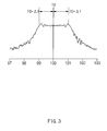
FIG. 3 is an exemplified diagram of a frequency spreading phenomenon in an LDC analog controller according to embodiments of the present disclosure; -
FIG. 4 is an exemplified diagram of a triangular wave generated by the apparatus for generating a switching signal for an analog controller according to embodiments of the present disclosure; -
FIG. 5 is an exemplified diagram of an output waveform of an LDC analog controller to which embodiments of the present disclosure are applied; -
FIG. 6A is an exemplified diagram illustrating an improvement effect of an electromagnetic wave generated by the apparatus for generating a switching signal for an analog controller according to embodiments of the present disclosure; and -
FIG. 6B is another exemplified diagram illustrating an improvement effect of an electromagnetic wave generated by the apparatus for generating a switching signal for an analog controller according to embodiments of the present disclosure. - Hereinafter, embodiments of the present disclosure will be described in detail with reference to the accompanying drawings.
- The terminology used herein is for the purpose of describing particular embodiments only and is not intended to be limiting of the disclosure. As used herein, the singular forms "a", "an" and "the" are intended to include the plural forms as well, unless the context clearly indicates otherwise. It will be further understood that the terms "comprises" and/or "comprising," when used in this specification, specify the presence of stated features, integers, steps, operations, elements, and/or components, but do not preclude the presence or addition of one or more other features, integers, steps, operations, elements, components, and/or groups thereof. As used herein, the term "and/or" includes any and all combinations of one or more of the associated listed items.
- It is understood that the term "vehicle" or "vehicular" or other similar term as used herein is inclusive of motor vehicles in general such as passenger automobiles including sports utility vehicles (SUV), buses, trucks, various commercial vehicles, watercraft including a variety of boats and ships, aircraft, and the like, and includes hybrid vehicles, electric vehicles, plug-in hybrid electric vehicles, hydrogen-powered vehicles and other alternative fuel vehicles (e.g., fuels derived from resources other than petroleum). As referred to herein, a hybrid vehicle is a vehicle that has two or more sources of power, for example both gasoline-powered and electric-powered vehicles.
- Additionally, it is understood that one or more of the below methods, or aspects thereof, may be executed by at least one controller. The term "controller" may refer to a hardware device that includes a memory and a processor. The memory is configured to store program instructions, and the processor is specifically programmed to execute the program instructions to perform one or more processes which are described further below. Moreover, it is understood that the below processes may be executed by an apparatus comprising the controller in conjunction with other components.
-
FIG. 1 is a configuration diagram of an apparatus for generating a switching signal for an analog controller according to embodiments of the present disclosure. As illustrated inFIG. 1 , the apparatus for generating a switching signal for an analog controller according to embodiments of the present disclosure includes avoltage setting unit 10, a period adjuster 20, atriangular wave generator 30, an alternating current (AC)component passing unit 40, and an LDCanalog controller 50. - Describing each component, first, the
voltage setting unit 10 sets voltages Vref_high and Vref_low of a triangular wave. That is, thevoltage setting unit 10 sets a maximum voltage Vref_high and a minimum voltage Vref_low of the triangular wave. Next, the period adjuster 20 adjusts a generation period of the triangular wave which is generated by thetriangular wave generator 30. That is, the period adjuster 20 controls thetriangular wave generator 30 to generate the triangular wave at a preset period. Next, thetriangular wave generator 30 generates the triangular wave at a period set by the period adjuster 20 based on the voltage set by thevoltage setting unit 10. - Next, the AC
component passing unit 40 passes through the AC component of the triangular wave generated by thetriangular wave generator 30 and blocks a direct current (DC) component. That is, the ACcomponent passing unit 40 transfers the AC component of the triangular wave generated by thetriangular wave generator 30 to the LDCanalog controller 50 and does not transfer the DC component of the triangular wave to the LDCanalog controller 50. That is, the ACcomponent passing unit 40 passes through only the AC component of the triangular wave independent of an offset. - Next, the LDC
analog controller 50 controls the LDC based on the AC component of the triangular wave passing through the ACcomponent passing unit 40. In this case, the voltage set by thevoltage setting unit 10 corresponds to a spreading range of a switching frequency of the LDC analog controller 50 (the spreading range is determined depending on the voltage) and the period adjusted by theperiod adjuster 20 corresponds to the modulation rate of the LDC analog controller 50 (the modulation rate is determined depending on the period). Because the LDCanalog controller 50 controls the LDC based on a current, the spreading phenomenon occurs. -
FIG. 2 is a circuit diagram of an apparatus for generating a switching signal for an analog controller according to embodiments of the present disclosure. As illustrated inFIG. 2 , the ACcomponent passing unit 40, the period adjuster 20, and thetriangular wave generator 30 are sequentially connected to an Rt terminal of the LDCanalog controller 50. In this configuration, the ACcomponent passing unit 40 has a simple structure of a capacitor and a resistor to block the DC component of the triangular wave and pass through only the AC component. - As illustrated in
FIG. 3 , the frequency spreading phenomenon occurs in theLDC analog controller 50 receiving the AC component of the triangular wave passing through the ACcomponent passing unit 40. In this case, the frequency spreading range is determined by a voltage range of the triangular wave and the frequency spreading range f0 ± Δf has a reference frequency (100 kHz) ± 10%. Hereinafter, the triangular wave generated by a circuit for generating a triangular wave will be described in more detail with reference toFIG. 4 . - As illustrated in
FIG. 4 , the voltage range corresponding to the frequency range is 3 V and the modulation rate corresponds to the period. Here, an arrow represents a current direction, and when a current represents a difference value, the voltage is 2.78 V as the maximum value Vref_high and when the current is branched, the voltage is 2.22 V as the minimum value Vlef_low. In this case, the maximum value and the minimum value may be calculated based on the following Table 1.[Table 1] V(Ref_High) 2.78V 5×R2/{(R1 ∥ R3)+R2} V(Ref_Low) 2.22V 5×(R1 ∥ R3)/{(R1 ∥ R2)+R2} -
FIG. 5 is an exemplified diagram of an output waveform of an LDC analog controller to which the embodiments of the present disclosure are applied. An output waveform ofFIG. 5 is a signal of which the frequency is spread by the triangular wave generated by the apparatus for generating a switching signal according to embodiments of the present disclosure, in which a frequency modulation rate of the triangular wave is 5.12 ms, a frequency spreading range is 570 mV, and afrequency fluctuation range 510 is 215.4 kHz which is increased by 9.8% from 196.1 kHz and is 174.4 kHZ which is reduced by 11.1% from 196.1 kHz. Here, the frequency fluctuation range is a frequency distribution diagram, in which the larger the frequency range, the wider the spreading width. -
FIG. 6A is an exemplified diagram illustrating an improvement effect of an electromagnetic wave generated by the apparatus for generating a switching signal for an analog controller according to embodiments of the present disclosure.FIG. 6A is a graph illustrating an electromagnetic wave measured at a low voltage output terminal (low voltage +), in which the a circular dottedline portion 610 in an AM band (530 kHz to 1.8 MHz) represents 29dB in average, which is a value reduced by 10 dB or more, as compared with the case in which the apparatus for generating a switching signal according to embodiments of the present disclosure is not applied. -
FIG. 6B is another exemplified diagram illustrating an improvement effect of an electromagnetic wave generated by the apparatus for generating a switching signal for an analog controller according to embodiments of the present disclosure.FIG. 6B is a graph illustrating an electromagnetic wave measured at an LDC output terminal, in which the a circular dottedline portion 620 in an AM band (530 kHz to 1.8 MHz) represents 58 dB in average, which is a value reduced by 10 dB or more, as compared with the case in which the apparatus for generating a switching signal according to embodiments of the present disclosure is not applied. - As set forth above, according to embodiments of the present disclosure, it is possible to allow the analog pulse width modulation (PWM) controller of the LDC for the hybrid vehicle or the electric vehicle to have the frequency spreading range corresponding to the preset voltages Vref_high and Vref_low and the modulation rate corresponding to the preset period, by generating the triangular wave as the switching signal at the preset voltages Vref_high and Vlef_low and the preset period. Further, it is possible to reduce the noise due to the high speed switching by allowing the analog PWM controller of the LDC for the hybrid vehicle or the electric vehicle to have the frequency spreading range corresponding to the preset voltages and the modulation rate corresponding to the preset period. Further, according to embodiments of the present disclosure, it is possible to remove the radio frequency interference (RFI) by reducing noise due to the high speed switching.
- The present disclosure described above may be variously substituted, altered, and modified by those skilled in the art to which the present disclosure pertains without departing from the scope and sprit of the present disclosure. Therefore, the present disclosure is not limited to the above-mentioned embodiments and the accompanying drawings.
-
- 10:
- VOLTAGE SETTING UNIT
- 20:
- PERIOD ADJUSTER
- 30:
- TRIANGULAR WAVE GENERATOR
- 40:
- AC COMPONENT PASSING UNIT
- 50:
- LDC ANALOG CONTROLLER
Claims (5)
- An apparatus for generating a switching signal for an analog controller, comprising:a voltage setting unit configured to set voltages Vref_high and Vlef_low of a triangular wave;a period adjuster configured to adjust a period of the triangular wave;a triangular wave generator configured to generate the triangular wave at the period based on the voltages set by the voltage setting unit; andan AC component passing unit configured to pass an AC component of the triangular wave through a low voltage DC-DC converter (LDC) analog controller.
- The apparatus according to claim 1, wherein the AC component passing unit passes through only the AC component of the triangular wave independent of an offset.
- The apparatus according to claim 1, wherein the AC component passing unit includes a capacitor and a resistor.
- The apparatus according to claim 1, wherein the voltages determine a spreading range of a switching frequency of the LDC analog controller.
- The apparatus according to claim 1, wherein the period determines a modulation rate of the LDC analog controller.
Applications Claiming Priority (1)
| Application Number | Priority Date | Filing Date | Title |
|---|---|---|---|
| KR20140136640 | 2014-10-10 |
Publications (1)
| Publication Number | Publication Date |
|---|---|
| EP3007340A1 true EP3007340A1 (en) | 2016-04-13 |
Family
ID=52987892
Family Applications (1)
| Application Number | Title | Priority Date | Filing Date |
|---|---|---|---|
| EP15161464.1A Withdrawn EP3007340A1 (en) | 2014-10-10 | 2015-03-27 | Square wave generator to dither carrier frequency in switched dc/dc converter |
Country Status (3)
| Country | Link |
|---|---|
| US (1) | US20160105164A1 (en) |
| EP (1) | EP3007340A1 (en) |
| CN (1) | CN106160707A (en) |
Families Citing this family (1)
| Publication number | Priority date | Publication date | Assignee | Title |
|---|---|---|---|---|
| CN107065626B (en) * | 2017-05-31 | 2019-06-14 | 广船国际有限公司 | Verification method, device and the network of ship system of voltage control performance |
Citations (1)
| Publication number | Priority date | Publication date | Assignee | Title |
|---|---|---|---|---|
| JP2011115028A (en) * | 2009-11-30 | 2011-06-09 | Nec Corp | Frequency diffusion circuit and frequency diffusion method used for power supply |
Family Cites Families (11)
| Publication number | Priority date | Publication date | Assignee | Title |
|---|---|---|---|---|
| US5912593A (en) * | 1997-06-09 | 1999-06-15 | Microchip Technology, Incorporated | IC (current-capacitor) precision oscillator having frequency and duty cycle controls |
| US6121802A (en) * | 1999-03-02 | 2000-09-19 | Stmicroelectronics, S.R.L. | Method and circuit for generating triangular waveforms opposite in phase |
| JP2005176476A (en) * | 2003-12-10 | 2005-06-30 | Seiko Instruments Inc | Switching regulator |
| JP2006187153A (en) * | 2004-12-28 | 2006-07-13 | Fujitsu Ltd | Semiconductor integrated circuit device, semiconductor circuit, DC-DC converter, control circuit for DC-DC converter, and control method for DC-DC converter |
| CN1848683B (en) * | 2005-04-15 | 2010-05-05 | 鸿富锦精密工业(深圳)有限公司 | Triangular wave generator and its pulse width modulation signal generating circuit |
| JP2007074190A (en) * | 2005-09-06 | 2007-03-22 | Rohm Co Ltd | Triangular wave generating circuit, pulse width modulator using the same, and switching regulator |
| WO2008092033A1 (en) * | 2007-01-25 | 2008-07-31 | Rgb Systems, Inc. | Method and apparatus for producing triangular waveform with low audio band noise content |
| JP5146022B2 (en) * | 2008-03-10 | 2013-02-20 | 株式会社リコー | DC-DC converter |
| CN101394166B (en) * | 2008-10-28 | 2011-08-10 | 深圳市矽普特科技有限公司 | Triangle wave generating circuit, pulse width modulation circuit and audio power amplifying circuit |
| TWI436594B (en) * | 2009-03-13 | 2014-05-01 | Richtek Technology Corp | Step-up and down power supply converter and control method thereof and sawtooth wave generator and method for applying the same in the step-up and step-down power supply converter |
| KR101339279B1 (en) * | 2012-12-18 | 2014-01-06 | 기아자동차 주식회사 | Method and apparatus for controlling converter in full cell vehicle |
-
2015
- 2015-03-21 US US14/664,819 patent/US20160105164A1/en not_active Abandoned
- 2015-03-27 EP EP15161464.1A patent/EP3007340A1/en not_active Withdrawn
- 2015-04-13 CN CN201510173997.5A patent/CN106160707A/en active Pending
Patent Citations (1)
| Publication number | Priority date | Publication date | Assignee | Title |
|---|---|---|---|---|
| JP2011115028A (en) * | 2009-11-30 | 2011-06-09 | Nec Corp | Frequency diffusion circuit and frequency diffusion method used for power supply |
Also Published As
| Publication number | Publication date |
|---|---|
| CN106160707A (en) | 2016-11-23 |
| US20160105164A1 (en) | 2016-04-14 |
Similar Documents
| Publication | Publication Date | Title |
|---|---|---|
| US10027262B2 (en) | Pseudorandom PWM variation based on motor operating point | |
| US10236803B2 (en) | Hybrid-vehicle variable-voltage traction motor drive | |
| US7417393B2 (en) | Load driver capable of suppressing overcurrent | |
| DE112008002482B4 (en) | Control device for an electric lathe | |
| US9878622B2 (en) | Power supply apparatus for eco-friendly vehicle | |
| US10266170B2 (en) | Controller for hybrid vehicle | |
| KR101787823B1 (en) | Electrically-driven vehicle | |
| US8274247B2 (en) | Rotary electric machine control system | |
| KR101795380B1 (en) | System and method for reducing torque motor speed ripple of eco-friendly vehicles | |
| CN108306488B (en) | Variable voltage converter for obtaining lower minimum step-up ratio | |
| EP1717945B1 (en) | Motor driving apparatus | |
| US11558000B2 (en) | Motor control device and electric vehicle system using the same | |
| DE102018103404A1 (en) | SYSTEM AND METHOD FOR NOISE REDUCTION IN ELECTRIFIED VEHICLE TRANSMISSION LINES WITH ELECTRIC MULTI-THREE PHASE DRIVE | |
| CN106256595B (en) | Inverter control method for hybrid vehicle | |
| CN107031615A (en) | Motor vehicle driven by mixed power and the method for controlling motor vehicle driven by mixed power | |
| US10790763B2 (en) | HEV e-drives with HV boost ratio and wide DC bus voltage range | |
| CN102122914A (en) | Induction motor control systems and methods | |
| US9827867B2 (en) | Electric powered vehicle | |
| US9793848B2 (en) | Driving apparatus for switching element | |
| WO2011061853A1 (en) | Vehicle ac generator control device | |
| JP2018133907A (en) | Charge control device | |
| US20160105164A1 (en) | Apparatus for generating switching signal for analog controller | |
| CN110149048A (en) | Boost converter device and control method of boost converter device | |
| JP2020162371A (en) | Converter control method and control device | |
| Kang et al. | A controller design for a stability improvement of an integrated charging system in hybrid electric vehicle |
Legal Events
| Date | Code | Title | Description |
|---|---|---|---|
| PUAI | Public reference made under article 153(3) epc to a published international application that has entered the european phase |
Free format text: ORIGINAL CODE: 0009012 |
|
| AK | Designated contracting states |
Kind code of ref document: A1 Designated state(s): AL AT BE BG CH CY CZ DE DK EE ES FI FR GB GR HR HU IE IS IT LI LT LU LV MC MK MT NL NO PL PT RO RS SE SI SK SM TR |
|
| AX | Request for extension of the european patent |
Extension state: BA ME |
|
| STAA | Information on the status of an ep patent application or granted ep patent |
Free format text: STATUS: THE APPLICATION HAS BEEN PUBLISHED |
|
| STAA | Information on the status of an ep patent application or granted ep patent |
Free format text: STATUS: THE APPLICATION IS DEEMED TO BE WITHDRAWN |
|
| 18D | Application deemed to be withdrawn |
Effective date: 20161014 |