EP3007318A1 - Multiple-polyphase ac dynamo-electric machine and electric power steering device - Google Patents
Multiple-polyphase ac dynamo-electric machine and electric power steering device Download PDFInfo
- Publication number
- EP3007318A1 EP3007318A1 EP13885843.6A EP13885843A EP3007318A1 EP 3007318 A1 EP3007318 A1 EP 3007318A1 EP 13885843 A EP13885843 A EP 13885843A EP 3007318 A1 EP3007318 A1 EP 3007318A1
- Authority
- EP
- European Patent Office
- Prior art keywords
- connection part
- teeth
- dynamo
- rotor
- polyphase
- Prior art date
- Legal status (The legal status is an assumption and is not a legal conclusion. Google has not performed a legal analysis and makes no representation as to the accuracy of the status listed.)
- Granted
Links
Images







Classifications
-
- H—ELECTRICITY
- H02—GENERATION; CONVERSION OR DISTRIBUTION OF ELECTRIC POWER
- H02K—DYNAMO-ELECTRIC MACHINES
- H02K1/00—Details of the magnetic circuit
- H02K1/06—Details of the magnetic circuit characterised by the shape, form or construction
- H02K1/12—Stationary parts of the magnetic circuit
- H02K1/16—Stator cores with slots for windings
- H02K1/165—Shape, form or location of the slots
-
- H—ELECTRICITY
- H02—GENERATION; CONVERSION OR DISTRIBUTION OF ELECTRIC POWER
- H02K—DYNAMO-ELECTRIC MACHINES
- H02K1/00—Details of the magnetic circuit
- H02K1/06—Details of the magnetic circuit characterised by the shape, form or construction
- H02K1/12—Stationary parts of the magnetic circuit
- H02K1/16—Stator cores with slots for windings
-
- H—ELECTRICITY
- H02—GENERATION; CONVERSION OR DISTRIBUTION OF ELECTRIC POWER
- H02K—DYNAMO-ELECTRIC MACHINES
- H02K3/00—Details of windings
- H02K3/04—Windings characterised by the conductor shape, form or construction, e.g. with bar conductors
- H02K3/28—Layout of windings or of connections between windings
-
- H—ELECTRICITY
- H02—GENERATION; CONVERSION OR DISTRIBUTION OF ELECTRIC POWER
- H02K—DYNAMO-ELECTRIC MACHINES
- H02K29/00—Motors or generators having non-mechanical commutating devices, e.g. discharge tubes or semiconductor devices
- H02K29/03—Motors or generators having non-mechanical commutating devices, e.g. discharge tubes or semiconductor devices with a magnetic circuit specially adapted for avoiding torque ripples or self-starting problems
Definitions
- the invention relates to a multiple-polyphase AC dynamo-electric machine that is used for a motor of a vehicle using power steering, in particular the stator that is the structure of the armature, and an electric power steering device.
- Patent Document 1 there is a structure of a multiple-polyphase motor that owns multiple groups in one of the AC motor of the group of polyphase that is composed by the invertor driving the polyphase and the polyphase aforesaid. Further, as in Patent Document 2, there is a permanent magnet motor which reduce the cogging torque.
- the present invention has been made in order to solve such a problem, in a multiple polyphase AC dynamo-electric machine that provides the armature that owns multiple polyphase group winded around the stator iron core that provides plurality of magnetism teeth and the aforesaid teeth, and the rotor that is relatively positioned through the magnetic air gap, it is intended and it is an object to effectively control the voltage generated and interlinked to one of the group that has generated the magnetic flux by the passage of the electric current in one group.
- the present invention relate to a multiple-polyphase AC dynamo-electric machine that provides an armature having a stator core having a plurality of magnetic teeth, and an armature winding containing the multiple polyphase winding group stored in slots between each of the teeth and winded around the teeth, a rotor that is relatively positioned to the armature through the magnetic air gap and rotates around an axis of a rotation shaft, wherein each of the plurality of the teeth provides the flange part to the NS magnetic pole part of the rotor side end part, the stator core has a magnetic connection part which connects the flange parts adjoined each other in the NS magnetic pole of each of the plurality of teeth, the connection part is provided corresponding to each of the slot and an inner peripheral side of the corresponding slot, the radial width of the connection part are smaller than both of the circumferential width of the teeth, since both are smaller than the circumferential width and radial width of the flange portion of the tooth, the voltage generated and interlinked
- a multiple-polyphase AC dynamo-electric machine that provides an armature having a stator core having a plurality of magnetic teeth, and an armature winding containing the multiple polyphase winding group stored in slots between each of the teeth and winded around the teeth, a rotor that is relatively positioned to the armature through the magnetic air gap and rotates around an axis of a rotation shaft, wherein the connection part is provided corresponding to each of the slot to one part of several positions in the axial direction of the stator core and the corresponding inner peripheral side of the corresponding slot, the connection part is also disposed in the slot supplied by any of the group of the armature winding composed of the multiple polyphase, because the aforesaid connection part is also arranged in the armature phase dedicated slots of each of the phase group of the armature phase composed of the polyphase group above-mentioned, for the balance of the magnetism circuit of all the phases and the inductance balance be favorable, the imbalance in current between the phase
- a multiple-polyphase AC dynamo-electric machine providesan armature having a stator core having a plurality of magnetic teeth, and an armature winding containing the multiple polyphase winding group stored in slots between each of the teeth and winded around the teeth, a rotor that is relatively positioned to the armature through the magnetic air gap and rotates around an axis of a rotation shaft, wherein each of the plurality of the teeth provides the flange part to the NS magnetic pole part of the rotor side end part, the stator core has a magnetic connection part which connects the flange parts adjoined each other in the NS magnetic pole of each of the plurality of teeth, the connection part is provided corresponding to each of the slot and an inner peripheral side of the corresponding slot, the radial width of the connection part are smaller than both of the circumferential width of the teeth, it is possible to control effectively the voltage generated on the winding group to the magnetic flux generated by the passage of the electric current of the space of the wind
- a multiple-polyphase AC dynamo-electric machine that provides an armature having a stator core having a plurality of magnetic teeth, and an armature winding containing the multiple polyphase winding group stored in slots between each of the teeth and winded around the teeth, a rotor that is relatively positioned to the armature through the magnetic air gap and rotates around an axis of a rotation shaft, wherein the connection part is provided corresponding to each of the slot to one part of several positions in the axial direction of the stator core and the corresponding inner peripheral side of the corresponding slot, the connection part is also disposed in the slot supplied by any of the group of the armature winding composed of the multiple polyphase, because the aforesaid connection part is also arranged in the armature phase dedicated slots of each of the phase group of the armature phase composed of the polyphase group above-mentioned, since the magnetic circuit balance of all the coil group and the inductance balance is improved, the imbalance in current between the wind
- the first embodiment has the particularity to represents an example of a multiple polyphase AC dynamo-electric machine that provides an stator core furnished by multiple magnetic teeth, an armature that owns the armature winding composed of the multiple polyphase winding supplied by the teeth of the slot wound around the teeth afore-mentioned, and a rotor that rotates in the axis of direction relatively disposed through a magnetic air gap, each of the plurality of teeth is provided with a flange part on the magnetic pole part of the rotor end part of the rotor side, the stator core has a magnetic connection part connected between the flange part above-mentioned adjoined to the NS magnetic pole of each of the plurality of teeth above-mentioned, the aforesaid connection part is provided on an inner peripheral side of the aforesaid slot which corresponds to each of the slots, the radial width of the aforesaid connection part is smaller than any of the circumferential width and radial width of the
- Fig 4 is a diagram in longitudinal view showing an example of an electric driving unit, as an illustration in Fig 4 in the present invention, the electric drive unit is illustrated together with the multiple polyphase AC motor and the electronic control unit (ECU) as example.
- Fig 5 is a diagram showing a cross section of the extending direction of the rotation axis that composes the multiple polyphase AC motor.
- the multiple polyphase AC dynamo-electric motor 4 will be explain by the vertical side structure Fig 4 .
- the multiple polyphase AC motor (dynamo-electric machine) 4 owns, the stator core 401 constructed by stacking the electromagnetic steel sheet, the armature winding 402 supplied by the stator core, and the frame 403 that fixes the stator core 401. Furthermore, the frame 403 is fixed by the bolt 405 and the housing 404provided on the front part of the motor.
- a bearing A (406) is provided, the bearing A (406) and the bearing B (407) supports together the freely rotation of the axis of revolution 408.
- a bearing A (406) is provided, the bearing A (406) and the bearing B (407) supports together the freely rotation of the axis of revolution 408.
- the stator core 410 is press-fitted on the axis of revolution 408 and a permanent magnet 411 is fixed on the stator core 410.
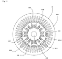
- the armature 5 owns the stator core 401 composed of the magnetic body made by the 48 teeth 501 where the equally spaced magnetic air gap space direction is projected, as well as the 48 slots 502 created by the teeth, the armature coil accommodated in the 48 slots 502 of the stator core 401, and the armature winding 402 connected by certain pattern on the outside of the armature coil.
- the teeth 501 of the stator core 401 provides the flange part 5012 created by the circumferential direction from the teeth to the front end part of the magnetic air gap space direction, also, a part of the radially inner circumference of the adjacent flange part 5012 is connected by the magnetic connection part 5011.
- the inner circumference of the connection strength of the rotor 503 of the stator core 401 rises and the vibrations of the motor are decreased, furthermore, the projections from the stator core 401 of the armature winding 402 are effectively prevented.
- connection part becomes the path of the magnetic flux to increase the inductance Ld of the d-axis rotor, it is possible to strengthen the effect of the weakening control field, as the voltage saturation can be alleviate, it is possible to improve the high rotational torque of the motor.
- the rotor owns the iron core rotor made of magnetic body, and the permanent magnet that generates the 8 fields installed in the iron core rotor above-mentioned.
- a rotating shaft if provided in the center of the iron core rotor.
- a permanent magnet is disposed in the interior of the iron core rotor, but it is also possible to dispose a permanent magnet on the surface of the iron core rotor as shown in Fig 6 .
- the 6 armature winding 402 (U1, V1, W1, U2, V2, W2) are split in the group 1 (U1, V1, W1) and the group 2 (U2, V2, W2) and extended over a multitude of teeth 501 in the 48 slots 502 created by the stator core 401,
- Fig 7 is a cross-section view showing a winding method of the multiple-polyphase AC motor in fig 5 , the symbols [+] and [-] indicates that the winding polarity is reversed to each other. Also, each winding is inserted by the same number of turns in the slot 502 to fix the armature winding 402.
- the armature winding 402 in each group are connected to each other, the group one of the armature winding (first winding group) and the group two of the armature winding (second winding group) are separated electrically without being connected.
- the method consisting of extending over multiple teeth across the armature winding is generally called distributed winding, in general, since the harmonic components of the magneto-motive force of the armature winding are reduced, the torque pulsation decreases.
- the brushless motor on the present embodiment has an electrically phase difference of a 30° electric angle.
- the coil pitch of the winding is set to 180° to all the pitch winding. As shown in Fig 1 , these winding groups are connected respectively by Y or ⁇ connections, and are disposed to be duplicated in 2.
- Fig 8 is a circuit diagram showing a motor driving method and a motor driving device of the multiple-polyphase AC motor.
- the 6 armature windings (U1, V1, W1, U2, V2, W2) of the multiple polyphase AC motor are connected mutually to U1, U1 and U2, U2, V1 and V1, V2 and V2, W1 and w1, W2 and W2 to the three terminals (U1, V1, W1) of the first inverter (motor driving device) 1 (81), and to the three terminals (U2, V2, W2) of the second inverter (motor driving device) 2 (82).
- the first inverter (motor driving device) 1 (81) and the second inverter (motor driving device) 2 (82) are disposed in the inner part on the ECU (Electronic Control Unit) 8.
- ECU8 may also be a different shape configured to be integrated to the motor.
- the ECU8 is configured to be integrated to the motor, it is necessary to provide six connection lines between the motor 4 and ECU8 if the motor 8 and the ECU8, moreover the size that became longer, the cost and the weight become a disadvantage, if the motor 4 and the ECU8 are assembled together as shown in Fig 4 , the six connection lines become shorter, the size, the cost and the weight become advantageous.
- ECU8 as illustrated in Fig 4 is assembled to the motor 4 through the heat sink 841, and is composed of the control circuit board 842 that have loaded the main function part of the ECU, the switching element 843 composed of the double inverter later mention, the middle component 844, the case 845 and such.
- the sensor part 412 composed of the magnetic sensor 847 that interacts with the sensor of the permanent magnet 846 mounted on the axis of revolution 408, the sensor circuit board 848 is loaded in the heat sink 841, the output of the sensor part 413 is sent to the main function part of the ECU of the control circuit board 842 through the connector component 850 supported by the support part 849.
- Fig 1 is a diagram of the connection of the armature winding of the double three-phase winding motor.
- Fig 1 ( a) shows the connection ⁇ .
- Fig 1 (b) shows the connection Y.
- the present invention can be applied either to the connection Y and the connection ⁇ .
- the circuit equivalence of the U1 phase of the first group and the U2 phase of the second group may be represented as in the Fig 2 .
- vu is each terminal voltage of the winding
- iu is the electric current
- R is the resistance
- lm is the leakage inductance
- M represents the mutual inductance
- 1 or 2 of the subscripts indicates the primary or secondary side.
- n is the turns ratio referred to the transformer.
- lm and M are different from the value used in a normal motor control, the inductance between the multiple two phases are arranged in parallel.
- V1 phase and V2 phase, W1 phase and W2 phase, U1 phase and V2 phase, U1 phase and W2 phase, V1 phase and U2 phase, V1 phase and W2 phase, W1 phase and U2 phase, W1 phase and V2 phase are the same as Fig 2 , in the case of a triphase equilibrium, even if the coordinate transformation is perfomed in the dq axis rotor from the UVW triphase, the equivalence circuit in the dq axis is the same as the one shown in Fig 2 .
- Fig 3 is bloc diagram form showing the equivalence circuit of the q axis when there is a coordinate transformation in the two phase dq axis rotor.
- vq1 and vq2 are the voltage of the q axis respectively to the group 1 and the group 2
- iq1 and iq1 are the electric current of the q axis respectively to the group 1 and the group 2
- lq1 and lq2 are the q axis component of the self-inductance of the winding respectively to the group 1 and the group 2
- Ra1 and Ra2 are the resistance component of the winding respectively to the group 1 and the group 2
- Mq12 and Mq21 are the q axis component of the mutual inductance of the winding between the first group and the second group.
- s represents the differential operator of the Laplace transform.
- vq12 and vq21 are the noise voltage placed on the group 1 and the group 2, according to the mutual inductance between the group 1 and the
- Fig 3 illustrates an equivalent circuit of the q axis rotor, but the equivalent circuit of the d axis rotor have the same configuration. Since the noise voltage is proportional to the differential value s that is the control response frequency of the electric current, given that the electric current become larger in the motor control when control in high-speed, the motor control that cancels the torque pulsation on the high response frequency becomes difficult. In particular in providing a magnetic material connection part in the stator core, since the magnetic permeability of the magnetic material is larger than the air, the magnetic resistance gap is reduced locally, the mutual inductance is also likely to increase.
- the noise voltage acts on each other, for the electric current control system the noise value acts as iq1 and iq1.
- iq1 and iq2 are the winding q axis current of each of the respectively group 1 and group 2
- Ra1 and Ra2 are the winding resistance of the each of the respectively group 1 and group 2
- Lq1 and Lq2 are the q axis component of the self-inductance of the winding phase of each of the respectively group 1 and group 2
- Mq12 is the q axis component of the mutual inductance that shows the interference of the winding group on the group 1 and group 2.
- a magnetic flux ⁇ M is generated in the chain path (hereinafter the path L) of the armature coil of the first winding group
- a magnetic flux ⁇ M is generated in the chain path (hereinafter the path M) of the armature coil of the first winding group.
- the self-inductance Lq1 is the ratio of the q axis component ⁇ L facing the q axis component rotor I1
- the mutual inductance Mq12 is the ratio of the q axis component ⁇ M facing the q axis component rotor I1
- the magnetism coupling Mq12/Lq1 has a strong correlation to ⁇ M/ ⁇ L.
- the magnetic flux flow is greatly inhibited by the path L and the path M.
- the magnetic flux amount ⁇ L and ⁇ M of the paths L and M has a strong correlation to the magnetic resistance of the connection part.
- the path L and the path M are different, the magnetic resistance that affects ⁇ M and ⁇ L is different.
- the magnetic coupling Mq12/Lq1 has a strong correlation in the magnetic resistance of each connection part in the path L and the path M.
- the magnetic resistance of the connection part changes from the non-linear particularity due to the magnetism saturation of the magnetic material, according by the magnetic flux amount of the unit cross-sectional area through the connection part. Furthermore, as the amount of magnetic flux per unit cross-sectional area through the connection part vary by the variation of the magnetic flux generated from the rotor and the armature winding due to the rotation of the motor, the magnetic resistance is increased in the path L, if the magnetic resistance decrease in the path M, ⁇ M / ⁇ L is increased, the magnetic coupling Mq12 / Lq1 increases. However, if the amount of magnetic flux per unit area passing through the connection part is increased, we understand that the magnetic resistance of the connection part is fixed regardless of the magnetic flux amount passing through the connection part according by the magnetism saturation.
- the connection part since one part of the adjoined flange part is connected, it is possible to compare and reduce the cross-sectional area when connecting all the flange parts to the cross-sectional area of the connection part. Therefore, it is possible to increase the amount of magnetic flux per unit cross-sectional area of the connection part, and the connection part can have a fixed value of the magnetic saturation regardless of the amount of magnetic flux passing through the connection part. Therefore, due to the rotation of the motor of the magnetic flux passing through the connection part, the magnetic resistance, ⁇ M, and ⁇ M don't vary greatly, and it becomes possible to decrease the magnetic coupling.
- Fig 9 is an enlarging explanation view of one part (3 teeth) of the stator core 401 in the Fig 5 .
- one part of the radial direction between the adjoined flange part 512 is connected by the magnetic flux connection part 5011 as described above, when the radial direction of the flange part 5012 is the width a, the width b of the radial direction of the flange part 5011 is smaller than the width a of the radial direction of the flange part 5012.
- the width b in the radial direction of the connection part 501 is smaller than the width b, the total area of the inner peripheral surface side of the connection part 5011 in the case of connecting all of the connection part 5011 is smaller than the total area of the inner peripheral surface of the flange part 5012 in the case of connecting all the flange part 5012.
- the space between the flange part 5012 is connected by the connection part 5011 on side of the rotor 503 of the stator core 401, but it is not limited to this position.
- the width b of the radial direction of the connection part 5011 is sufficiently smaller than the width cb of the radial direction of the core block 91 and the circumferential direction of the teeth 501 of the stator core.
- each of the connection part 5011, 5011, ... is equal to the number of slot 502, the magnetic resistance in the space of the both ends 401E, 401E of the axial direction (the extending direction of the axis of revolution 408) of the aforesaid axis of revolution 408 of the stator core 401 above-mentioned of each aforesaid connection part 5011, 5011, ... are substantially the same, and the magnetic resistance 4 on the aforesaid both end 401E, 401E space on the flange part 5012 above-mentioned is bigger.
- connection part 5011 By such a configuration, as the magnetic flux density of the width b of the connection part 5011 becomes greater, a magnetic saturation occurs, and it is possible to increase the magnetic resistance of the connection part 5011. As a result, since the leakage magnetic flux leaking through the connection part 5011 is reduced, it is possible to reduce the magnetic coupling between the winding group 1 and winding group 2, and the enhance of the controllability can be obtained.
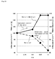
- Fig 22 is a graph showing the 1/(Mq12/Lq1) of the group 1 when changing the width b of the flange part 5011 regarding the width a of the flange part 5012.
- the self-inductance Ld1 component that affects the effects of the field weakening control described above is also mentioned.
- the connection strength of the stator core 401 is improved, the vibrations of the motor 4 are decreased, the protrude of the armature winding 402 from the stator core 401 is controlled, the cogging torque, torque ripple are reduced by reducing the harmonic components of the slot permeance, it becomes possible to improve the rotation torque of the motor by improving the inductance of the d axis rotor.
- Fig 10 (a) is an explanation diagram of the configuration in which the shape of the complex of the connection part 5011 and the flange part 5012 become step wised.
- the Fig shows an enlarged part of one of the cross-sectional shape of the motor in order to facilitate comprehension.
- the armature winding 402 is supplied by the slot 502 of the stator core which owns the core back 91, the teeth 501 and the slot 502.
- the 4 coils a1, a2, a3, a4 of the armature winding of the same phase is supplied by the slot 502.
- a component is necessary to isolate the slot and the armature winding, but it is omitted in the drawing.
- the flange part 5012 is provided by the NS magnetic pole part of the inner circumference of the teeth 501, further, the flange part 5012 is connected to the connection part 5011 to adjoin each other.
- the connection part 5011 is composed of a magnetic material.
- the rotor 503 is provided by the iron core rotor 108 and the permanent magnet 411.
- the outer diameter 11R of the rotor 503 has a radius Rout.
- the radius Rout is also defined by the tube.
- the radius Rout is defined by the most outer diameter of the stator core 108.
- the outline of the complex of the connection part 5011 and the flange part 5012 has a stair shape 501112S.
- the gap length g1 of the rotor 503 in the connection part 5011 have the same structure as the gap length g2 of the rotor 503 in the connection part 5011.
- the stair shape is 501112S
- the distance between the flange part 5012 adjoined to the can be in equal parts. Because of this, if the connection part 5011 have magnetism saturation, it is possible to reduce the leakage magnetic flux generated between the adjoined flange part 5012.
- the motor can have a downsizing effect. There is also the effect of reducing the amount of the permanent magnet 411. Furthermore, according to the fact that the aforesaid gap length in the flange part 5012 is the same as the aforesaid gap length in the flange part 5011, the pulsation permeance are reduced, and the torque pulsation becomes smaller.
- Fig 10 (b) is an explanation diagram of the configuration in which the complex shape of the connection part 5011 and the flange part 5012 become a curved shape 501112R.
- Fig shows an enlarged part of the cross-sectional shape of the motor in order to facilitate comprehension.
- the armature winding 402 is supplied by the slot 502 of the stator core 401 that owns the slot 502, the teeth 501 and the core back 91.
- the 4 coils b1, b2, b3 and b4 of the armature winding of the same phase are supplied by the slot 502.
- a component is required for the isolation between the armature winding and the slot, but it is omitted in the Fig.
- the flange part 5012 is created in the magnetic pole part of the inner circumference side of the teeth 501, furthermore, the adjoined flange part 5012 is connected by the connection part 5011.
- the connection part 5011 is composed of magnetic material.
- a metal pattern electromagnetic steel sheet is created.
- the rotor 503 is provided by the iron core rotor 108 and the permanent magnet 411.
- the outer diameter of the rotor 503 has a radius Rout. In the case where the permanent magnet owns an anti-scattering metallic tube, the radius Rout is also defined by the tube. When the permanent magnet is buried by the iron core rotor, the radius Rout is defined by the most outer diameter of the stator core.
- the rotor 503 owns the iron core rotor 108, the permanent magnet 411 generated by the field installed in the iron core rotor 108 above-mentioned, but it is not limited to this structure, for example as shown in Fig 11 it owns the winding field pole 111 generated by the rotor 503, as shown in Fig 12 there is a reluctance type rotor provided the protrusion part 121 by the iron core rotor 108, even if there is an induction machine, the similar argument as above-mentioned is completed.
- the winding group have an electrically phase difference of 30°
- the winding group 1 and winding group 2 are adjoined together in the 8 poles and 48 slots of the multiple polyphase AC motor, but the phase difference between the winding groups, located between the first and the second group, is not limited to the number of poles and the number of slots, the winding is electrically isolated in two parts, regarding the multiple polyphase AC motor driven by the each of the winding group in the different motor driving device, the same effects as above are obtained.
- the multiple polyphase AC motor where the number of poles is 2m, and the number of slot is 12m is provided by 2 motor driving device connected by separate two-three phase winding group above-mentioned, the winding group 1 and winding group 2 are disposed side by side, the winding pitch of the armature winding is at an electrical angle of 180° for the entire pitch.
- the aforesaid 2 motors driving device 81 and 82 when the electric current or the voltage that have a phase contrast of 30° in the two polyphase group above-mentioned are supplied, it is possible to have a maximum of 1 to the distributed winding coefficient of the motor and the short pitch winding factor, and the torque of the multiple polyphase AC motor is improved.
- the above description explain that the winding are electrically separated into two groups of winding, a multiple polyphase AC motor is driven by two different motor drive device 81 and 82, the same effect as described above can also be obtain when the number of the motor driving device 81 and 82 separated from the winding groups is increased. Also, in the flange part and the stator core of the present embodiment, even if the connection part of the adjoined flange part owns an stator core, teeth and other component, the same effect as described above can be obtained.
- the second embodiment represents a multiple polyphase AC dynamo-electric motor that has the particularity to provide an stator core furnished by multiple magnetic teeth, an armature that owns the armature winding composed of the multiple polyphase winding supplied by the teeth of the slot wound around the teeth afore-mentioned, and a rotor that rotates in the axis of direction relatively disposed through a magnetic air gap, each of the plurality of teeth is provided with a flange part on the magnetic pole part of the rotor end part of the rotor side, the stator core has a magnetic connection part connected between the flange part above-mentioned adjoined to the NS magnetic pole of each of the plurality of teeth above-mentioned, the aforesaid connection part is provided on an inner peripheral side of the aforesaid slot which corresponds to each of the slots, provided on the inner peripheral side of the corresponding slot, the connection part is also disposed in the aforesaid slots supplied by the armature winding
- Fig 13 is an enlarged part of the explanatory view of the stator core of the multiple polyphase AC motor.
- connection part 5011 is finely divided (thickness d1, d2, d3, d4) in the axial direction as shown in Fig 14 , the radial direction of the connection width b is smaller than the width a of the flange part, as described in Fig 15 .
- the magnetic resistance (the magnetic resistance of the total of d1 and d2 in Fig 13 , the magnetic resistance of the total of d1, d2, d3 and d4 in Fig 14 and 15 ) of the both ends 401E, 401E of the axial direction (the extending direction of the axis of revolution 408) of the stator core 401 above-mentioned of the connection parts 5011, 5011, .... are substantially the same, and larger than the magnetic resistance of the both ends 401E, 401E of the aforesaid flange part 5012.
- the vibration of the motor are reduced by improving the connection strength of the stator core 401, the jump out of the armature winding 402 of the stator core 401 are suppressed, the harmonic component of the of the slot permeance can be reduced, the cogging torque and the torque ripple are reduced, the high rotation torque of the motor is increased by improving the inductance of the rotor d axis.
- the magnetic coupling since it is possible to reduce the magnetic coupling, to increase the response of the current control system, and to improve the controllability of the motor. Also, it is possible to reduce variations due to the rotation of the inductance of the motor and the self-inductance of the motor, to improve the controllability of the motor, and to reduce the torque pulsation. Moreover, since only one part of the axial direction between the flange part 5012 is connected to the connection part 5011, it is possible to reduce the leakage flux in the armature that do not contribute to the torque, and it is possible to improve the torque.
- connection part 5011 and the flange part 5012 are shown as a stair shape, but it is not limited to this. It is also shown in the case of the inside diameter became curved or convex like in Fig 10 (b) . Even in this case, the same effect is described in the first embodiment.
- the width of the radial direction of the connection part 5011 above-mentioned is set to the half of the radial width of the flange part 5012, as the inductance is not so much reduced together with the improvment of the control, the weak magnetic flux control shows effects, and the number of revolutions of the motor (dynamo-electric machine) are maintained.
- connection part is established by the inner radial direction of the adjacent slot. It is shown that the connection part is arranged according by the slot dedicated to the first and second armature winding group. From the Fig 13 and 14 , the connection part is arranged through one part of the axial direction of the stator core.
- the multiple polyphase AC dynamo-electric machine of the present embodiment is configured that the aforesaid connection part is arranged through one part of the axial direction of the stator core, inside the armature winding composed of multiple winding groups, the connection part is arranged according by the slot dedicated to the first and second armature winding group.
- Fig 16 is an explanatory view showing the relationship between the stator core 401 and the iron core rotor 108.
- the width a of the flange part 5012 is larger than the gap width g of the gap between the stator core 108 and the iron core rotor 108, and the interval f between the flange part 5012 is smaller than the gap width g.
- the magnetic flux generated by the armature 5 is divided mainly with the rotor 503 and the connection part 5011 above-mentioned, but there is a strong correlation between the magnetic resistance of the connection part 5011 and the magnetic resistance of the magnetic air gap between the iron core rotor 108 and the stator core 401.
- the magnetic resistance of the magnetic air gap between the stator core 401 and the iron core rotor 108 has the characteristic to be proportional to the gap width g.
- the magnetic resistance in the case where the connection part 5011 is saturated there is dependence on the interval f between the space in the flange part 5012 and the width a of the flange part 5012, the width a of the flange part 5012 is larger, and the interval f of the flange part 5012 become smaller.
- the width a of the flange part 5012 is larger, if the interval f of the flange part 5012 become smaller, the magnetic resistance of the flange part 5011 become smaller than the magnetic resistance of the magnetic air gap between the iron core rotor 108 and the stator core 401, and it is possible to relatively enlarge the magnetic flux which flows in the side of the flange part 5012 adjoined from the flange part 5012 of the stator core 401. Therefore, in this embodiment the width a of the flange part 5012 is larger, since the interval f of the flange part 5012 is smaller than the gap width g, it is possible to increase the magnetic flux amount of the connection part 5011.
- the width a of the flange 5012 is grater than the gap width g, the interval f between the flange part 5012 is made smaller than the gap width g, but maybe because the width a of the flange part 5012 is greater than the gap width g, the same effect as above can be obtain even if the interval f of the flange part 5012 is smaller than the gap width g.
- Fig 17 is an enlarged part explanatory view of one part of the stator core of the multiple polyphase AC motor.
- the connection position between the adjoined flange part 5012 is in the circumferential direction.
- the total axial thickness of the connection part 5011 is smaller than the total thickness of the axial direction of the flange part 5012.
- the magnetic resistance of the both ends 401E of the axial direction (extending direction of the rotation axis 408) of the axial direction 408 above-mentioned of the stator core 401 of each of the connection part 5011, 5011, ... is substantially the same, and is larger than the magnetic resistance of the aforesaid both ends 401E of the flange part 5012 above-mentioned.
- connection position between the adjoined flange part 5012 is different in the circumferential direction, the harmonic component of the slot permeance of the slot 502 is changed by the connection position. It becomes possible to cancel an harmonic component of the slot permeance by combining the stator core in a different connection position, and it is possible to reduce the cogging torque and the torque pulsation.
- Fig 18 is an enlarged part explanatory view of one part of the stator core of a multiple polyphase AC motor.
- the stator core composition is different, the thin plate that owns the flange part 5011 connected to one part of the adjoined flange part 5011 by magnetic body, and the thin plate having no connection part are formed by stacking.
- the vibration of the motor can be reduced by improving the connection strength of the stator core 401, the jump out of the armature winding 402 of the stator core 401 is suppressed, the cogging torque and the torque ripple can be reduced by reducing the harmonic component of the slot permeance, it is possible to increase the high rotational torque of the motor by improving the inductance of the rotor d axis.
- the rotor can reduce the variation due to the inductance of the rotation of the motor when rotated, the controllability of the motor is improved, and it is possible to reduce the torque pulsation.
- only one part of the flange part is connecter, it is possible to reduce the leakage flux in the armature that does not contribute to the torque, and it is possible to improve the torque.
- Fig 19 is an explanatory diagram showing the flow of the magnetic flux of the connection part 5011.
- Fig 19 is an explanatory diagram showing the flow of the magnetic flux of the connection part 5011.
- the path A passing through the gap between the flange part 5012 and the path B passing through the gap between the flange part 5011 are divided in two. For this reason, since the thin plate used for the armature of the present embodiment has a film on the surface, the magnetic resistance in the stacking direction of the thin plate is greater than the magnetic resistance in the plane direction.
- the magnetic resistance of the path A passing through the gap between the flange part 5012 is fixed through the gap regardless of the magnetic flux amount.
- the magnetic resistance passing through the path B is fixed regardless of the magnetic flux amount. Therefore, since it is possible to be closed to fix to a constant value the magnetic resistance that the rotation of the motor changed by the magnetic flux amount of the connection part 5011, it is possible to reduce variations due to the rotation of the magnetic coupling, the self-inductance motor and the mutual inductance motor.
- the axial thickness of the flange part c the maximum value of the consecutive lamination thickness of the thin plate having no connection is set to h.
- Fig 20 is an explanatory diagram showing an example of the present embodiment.
- the magnetic flux of the path a of Fig 19 a thin plate having no connection part 5011 is increased relatively compared with the case of a not stacked thin plate as in Fig 18 , it is possible to be closed to fix to a constant value the magnetic resistance that the rotation of the motor changed by the magnetic flux amount of the connection part 5011, it is possible to reduce variations due to the rotation of the magnetic coupling, the self-inductance motor and the mutual inductance motor.
- the thin plate ( Fig 20 (b) ) which owns the connection part 5011 connected by a magnetic body to one part of the adjoined flange part 5012 and the thin plate ( Fig 20 (c) ) that doesn't own the connection part 5011 are stacked, since the stacked position in the axial direction of the thin above-mentioned is regulated, it is possible to reduce magnetic coupling even while improving the high rotational torque of the motor.
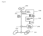
- Fig 21 is a diagram showing an electric power steering device that generates an assist torque by the multiple polyphase AC motor of the 1 to 5 embodiments.
- the driver of the compartment rotates the steering wheel 2101 to the left and right and performs steering to the front wheel 2102.
- Torque detection way 2103 detects the steering torque of the steering system and output a detection torque to the control way 2104.
- the control way 2104 operates voltage orders, and outputs it to the voltage application way 2106.
- the voltage application way 2106 applies voltage on the multiple polyphase AC motor 2105 based on the voltage orders, the multiple polyphase AC motor 2105 generates a torque assistance through the gear 2107.
- an electric power steering system equipped with a multiple polyphase AC motor 2105 as described in the present embodiment since the torque pulsation and cogging torque of the multiple polyphase AC motor is reduced, it is possible to improve the steering feeling on the handle of the driver by reducing the pulsation, the sound of the steering can be reduced. Further, since the vibration of the motor 2105 is reduced, it is possible to reduce the sound transmitted to the compartment, and to improve the quietness of the vehicle. Also, since the torque of the multiple polyphase AC motor is improved, the electric power steering device can be lighter, it is possible to improve the high rotation torque required such during emergency avoidance, or during torque rated value such as end contact steering time.
- the 1 to 6 embodiments have the following features.
Landscapes
- Engineering & Computer Science (AREA)
- Power Engineering (AREA)
- Iron Core Of Rotating Electric Machines (AREA)
- Windings For Motors And Generators (AREA)
- Control Of Ac Motors In General (AREA)
Abstract
Description
- The invention relates to a multiple-polyphase AC dynamo-electric machine that is used for a motor of a vehicle using power steering, in particular the stator that is the structure of the armature, and an electric power steering device.
- As in
Patent Document 1, there is a structure of a multiple-polyphase motor that owns multiple groups in one of the AC motor of the group of polyphase that is composed by the invertor driving the polyphase and the polyphase aforesaid. Further, as inPatent Document 2, there is a permanent magnet motor which reduce the cogging torque. - [Patent Literature 1] JPH7-264822A
- [Patent Literature 2]
JP4476202B - In a multiple-polyphase AC dynamo-electric machine, as in
Patent Document 2, if the teeth of the adjacent stator iron core are simply connected, by disposing closely the multiple group of the polyphase group, by chaining one of the polyphase group that produces the magnetic flux to other polyphase group through the connection part aforesaid, a voltage is generated in the other polyphase groups aforesaid.
Since the applied voltage for the passage of the electric current is superposed as a noise in the invertor of the other polyphase group, there is an issue that the motor control to offset the pulsation torque produced by the polyphase groups in the opposite phase becomes more difficult. - The present invention has been made in order to solve such a problem, in a multiple polyphase AC dynamo-electric machine that provides the armature that owns multiple polyphase group winded around the stator iron core that provides plurality of magnetism teeth and the aforesaid teeth, and the rotor that is relatively positioned through the magnetic air gap, it is intended and it is an object to effectively control the voltage generated and interlinked to one of the group that has generated the magnetic flux by the passage of the electric current in one group.
- The present invention relate to a multiple-polyphase AC dynamo-electric machine that provides an armature having a stator core having a plurality of magnetic teeth, and an armature winding containing the multiple polyphase winding group stored in slots between each of the teeth and winded around the teeth, a rotor that is relatively positioned to the armature through the magnetic air gap and rotates around an axis of a rotation shaft, wherein each of the plurality of the teeth provides the flange part to the NS magnetic pole part of the rotor side end part, the stator core has a magnetic connection part which connects the flange parts adjoined each other in the NS magnetic pole of each of the plurality of teeth, the connection part is provided corresponding to each of the slot and an inner peripheral side of the corresponding slot, the radial width of the connection part are smaller than both of the circumferential width of the teeth, since both are smaller than the circumferential width and radial width of the flange portion of the tooth, the voltage generated and interlinked to one of the group that has generated the magnetic flux by the passage of the electric current in one group if effectively controlled.
- Also, relate to a multiple-polyphase AC dynamo-electric machine that provides an armature having a stator core having a plurality of magnetic teeth, and an armature winding containing the multiple polyphase winding group stored in slots between each of the teeth and winded around the teeth, a rotor that is relatively positioned to the armature through the magnetic air gap and rotates around an axis of a rotation shaft, wherein the connection part is provided corresponding to each of the slot to one part of several positions in the axial direction of the stator core and the corresponding inner peripheral side of the corresponding slot, the connection part is also disposed in the slot supplied by any of the group of the armature winding composed of the multiple polyphase, because the aforesaid connection part is also arranged in the armature phase dedicated slots of each of the phase group of the armature phase composed of the polyphase group above-mentioned, for the balance of the magnetism circuit of all the phases and the inductance balance be favorable, the imbalance in current between the phase group decreases, the torque ripple become smaller, and the resulting vibration and noise is also reduced.
- According to the present invention, a multiple-polyphase AC dynamo-electric machine providesan armature having a stator core having a plurality of magnetic teeth, and an armature winding containing the multiple polyphase winding group stored in slots between each of the teeth and winded around the teeth, a rotor that is relatively positioned to the armature through the magnetic air gap and rotates around an axis of a rotation shaft, wherein each of the plurality of the teeth provides the flange part to the NS magnetic pole part of the rotor side end part, the stator core has a magnetic connection part which connects the flange parts adjoined each other in the NS magnetic pole of each of the plurality of teeth, the connection part is provided corresponding to each of the slot and an inner peripheral side of the corresponding slot, the radial width of the connection part are smaller than both of the circumferential width of the teeth, it is possible to control effectively the voltage generated on the winding group to the magnetic flux generated by the passage of the electric current of the space of the winding group, the voltage interferences between the winding group are effectively reduced, the pulsation torque due to the ripple component of the current to improve the response of the current control system is effectively reduced.
- Also, according to another invention, a multiple-polyphase AC dynamo-electric machine that provides an armature having a stator core having a plurality of magnetic teeth, and an armature winding containing the multiple polyphase winding group stored in slots between each of the teeth and winded around the teeth, a rotor that is relatively positioned to the armature through the magnetic air gap and rotates around an axis of a rotation shaft, wherein the connection part is provided corresponding to each of the slot to one part of several positions in the axial direction of the stator core and the corresponding inner peripheral side of the corresponding slot, the connection part is also disposed in the slot supplied by any of the group of the armature winding composed of the multiple polyphase, because the aforesaid connection part is also arranged in the armature phase dedicated slots of each of the phase group of the armature phase composed of the polyphase group above-mentioned, since the magnetic circuit balance of all the coil group and the inductance balance is improved, the imbalance in current between the winding groups is decreased, the torque ripple becomes smaller, and the resulted vibration and noise are reduced.
-
- [
Fig.1 ] Regarding to the first embodiment of the present invention,Fig 1 is an explanation view showing a method for connecting the armature of the multiple polyphase AC motor. - [
Fig.2 ] Regarding to the first embodiment of the present invention,Fig 2 is an explanation view showing an equivalent circuit of the armature winding between the groups. - [
Fig.3 ] Regarding to the first embodiment of the present invention,Fig 3 is an explanation view explaining the circuit configuration of the q-axis of the mulitple polyphase motor. - [
Fig.4 ] Regarding to the first embodiment of the present invention,Fig 4 is an explanation view of the electric drive unit. - [
Fig.5 ] Regarding to the first embodiment of the present invention,Fig 5 is a sectional view of the configuration of a mulitple polyphase motor. - [
Fig.6 ] Regarding to the first embodiment of the present invention,Fig 6 is a sectional view showing an example of a configutation of a multiple polyphase motor. - [
Fig.7 ] Regarding to the first embodiment of the present invention,Fig 7 is a sectional view showing a winding pattern of the multiple polyphase AC motor armature. - [
Fig.8 ] Regarding to the first embodiment of the present invention,Fig 8 is an explanation view of the motor drive unit. - [
Fig.9 ] Regarding to the first embodiment of the present invention,Fig 9 is an enlarged sectional view of the iron stator core of the multiple polyphase AC motor. - [
Fig.10 ] Regarding to the first embodiment of the present invention,Fig 10 is an explanation diagram of the shape of the connecting and the flang parts. - [
Fig.11 ] Regarding to the first embodiment of the present invention,Fig 11 is a sectional view showing an example of a rotor that owns the field pole generated by the field. - [
Fig.12 ] Regarding to the first embodiment of the present invention,Fig 12 is an explanation diagram showing an example of a reluctance type rotor without using the - [
Fig.13 ] Regarding to the second embodiment of the present invention,Fig 13 is an enlarged sectional view of the iron stator core of the multiple polyphase AC motor. - [
Fig.14 ] Regarding to the second embodiment of the present invention,Fig 14 is an explanation view as an example of the connection part, showing a case where the connection part is finely divided in the axial direction. - [
Fig.15 ] Regarding to the second embodiment of the present invention,Fig 15 is an explanation view as an example of the connection part, showing a case where the radical direction of the connection width b of the connection part is smaller than the width a of the flange. - [
Fig.16 ] Regarding to the third embodiment of the present invention,Fig 16 is an explanation view showing the relationship between the iron stator core and the rotor core. - [
Fig.17 ] Regarding to the fourth embodiment of the present invention,Fig 17 is an explanation view showing the case where there is a difference in the circumferential direction of the position of the connection part between the adjoined flange part. - [
Fig.18 ] Regarding to the fifth embodiment,Fig 18 is an enlarged explanation view showing the iron stator core of the multiple polyphase AC motor. - [
Fig.19 ] Regarding to the fifth embodiment,Fig 19 is an explanation view showing the magnetic flux path of the enlarged part of theFig 18 when there is passage of the electric current in one group. - [
Fig.20 ] Regarding to the fifth embodiment,Fig 20 is an explanation view explaining the case where a thin plate without connection part is continuously stacked. - [
Fig.21 ] Regarding to the sixth embodiment,Fig 21 is an explanation view showing the electric power steering unit - [
Fig.22] Fig 22 is an explanation view showing the change of inductance and magnetic coupling. - The first embodiment has the particularity to represents an example of a multiple polyphase AC dynamo-electric machine that provides an stator core furnished by multiple magnetic teeth, an armature that owns the armature winding composed of the multiple polyphase winding supplied by the teeth of the slot wound around the teeth afore-mentioned, and a rotor that rotates in the axis of direction relatively disposed through a magnetic air gap, each of the plurality of teeth is provided with a flange part on the magnetic pole part of the rotor end part of the rotor side, the stator core has a magnetic connection part connected between the flange part above-mentioned adjoined to the NS magnetic pole of each of the plurality of teeth above-mentioned, the aforesaid connection part is provided on an inner peripheral side of the aforesaid slot which corresponds to each of the slots, the radial width of the aforesaid connection part is smaller than any of the circumferential width and radial width of the flange part of the teeth.
Hereinafter, a second embodiment of multiple polyphase AC dynamo-electric motor will be described with reference toFigs. 1 to 12 in this order: - "Description of the electric drive unit", "description of the double inverter", "Description of problem", "Description of the noise voltage", description of the basic concept of the invention"," description of the magnetic resistance of the magnetic pole 1 (stair shape)", "description of the magnetic resistance of the magnetic pole 2 (curved shape)".
-
Fig 4 is a diagram in longitudinal view showing an example of an electric driving unit, as an illustration inFig 4 in the present invention, the electric drive unit is illustrated together with the multiple polyphase AC motor and the electronic control unit (ECU) as example.
Fig 5 , regarding the first of embodiment of the present invention, is a diagram showing a cross section of the extending direction of the rotation axis that composes the multiple polyphase AC motor. - First, the multiple polyphase AC dynamo-
electric motor 4 will be explain by the vertical side structureFig 4 .
The multiple polyphase AC motor (dynamo-electric machine) 4 owns, thestator core 401 constructed by stacking the electromagnetic steel sheet, the armature winding 402 supplied by the stator core, and theframe 403 that fixes thestator core 401.
Furthermore, theframe 403 is fixed by thebolt 405 and the housing 404provided on the front part of the motor.
On the housing 404 a bearing A (406) is provided, the bearing A (406) and the bearing B (407) supports together the freely rotation of the axis ofrevolution 408.
On the housing 404 a bearing A (406) is provided, the bearing A (406) and the bearing B (407) supports together the freely rotation of the axis ofrevolution 408.
Thestator core 410 is press-fitted on the axis ofrevolution 408 and apermanent magnet 411 is fixed on thestator core 410. - Next, the multiple polyphase motor will be explain in
Fig 5 by the structure of the cross section as viewed in the extending direction of its axis of rotation.
Thearmature 5 owns thestator core 401 composed of the magnetic body made by the 48teeth 501 where the equally spaced magnetic air gap space direction is projected, as well as the 48slots 502 created by the teeth, the armature coil accommodated in the 48slots 502 of thestator core 401, and the armature winding 402 connected by certain pattern on the outside of the armature coil. - Here, the
teeth 501 of thestator core 401 provides theflange part 5012 created by the circumferential direction from the teeth to the front end part of the magnetic air gap space direction, also, a part of the radially inner circumference of theadjacent flange part 5012 is connected by themagnetic connection part 5011.
In this way, by using eachteeth 501 adjoined to theflange part 5012 to form a structure connected by theconnection part 5011 in a part of those radially inner circumference, the inner circumference of the connection strength of therotor 503 of thestator core 401 rises and the vibrations of the motor are decreased, furthermore, the projections from thestator core 401 of the armature winding 402 are effectively prevented. - Also, when connecting the flange part in this way, since the aperture part of the rotor side of the aforesaid slot disappears, the harmonic component of slot permeance that causes the cogging torque and the torque pulsations can be decreased, the cogging torque and the torque pulsations are decreased.
- Furthermore, by connecting the flange part as described above, the connection part becomes the path of the magnetic flux to increase the inductance Ld of the d-axis rotor, it is possible to strengthen the effect of the weakening control field, as the voltage saturation can be alleviate, it is possible to improve the high rotational torque of the motor.
- Moreover, the rotor owns the iron core rotor made of magnetic body, and the permanent magnet that generates the 8 fields installed in the iron core rotor above-mentioned. Also, A rotating shaft if provided in the center of the iron core rotor.
Further, inFig 5 , a permanent magnet is disposed in the interior of the iron core rotor, but it is also possible to dispose a permanent magnet on the surface of the iron core rotor as shown inFig 6 . - Also, as shown in
Fig 6 , in the armature winding 402, the 6 armature winding 402 (U1, V1, W1, U2, V2, W2) are split in the group 1 (U1, V1, W1) and the group 2 (U2, V2, W2) and extended over a multitude ofteeth 501 in the 48slots 502 created by thestator core 401, - Here,
Fig 7 is a cross-section view showing a winding method of the multiple-polyphase AC motor infig 5 , the symbols [+] and [-] indicates that the winding polarity is reversed to each other.
Also, each winding is inserted by the same number of turns in theslot 502 to fix the armature winding 402.
Although the armature winding 402 in each group are connected to each other, the group one of the armature winding (first winding group) and the group two of the armature winding (second winding group) are separated electrically without being connected.
In this way, the method consisting of extending over multiple teeth across the armature winding is generally called distributed winding, in general, since the harmonic components of the magneto-motive force of the armature winding are reduced, the torque pulsation decreases. - Further, regarding the first winding group, when the second winding group rotate electrically to 360° the angle occupied in the circumferential direction of the pair of N and S poles of the rotor, the brushless motor on the present embodiment has an electrically phase difference of a 30° electric angle.
Further, when the angle occupied in the circumferential direction of the pair of N and S poles rotates electrically to 360°, the coil pitch of the winding is set to 180° to all the pitch winding.
As shown inFig 1 , these winding groups are connected respectively by Y or Δ connections, and are disposed to be duplicated in 2. - Regarding to the first embodiment of the present invention,
Fig 8 is a circuit diagram showing a motor driving method and a motor driving device of the multiple-polyphase AC motor.
As shown in the same figure, the 6 armature windings (U1, V1, W1, U2, V2, W2) of the multiple polyphase AC motor are connected mutually to U1, U1 and U2, U2, V1 and V1, V2 and V2, W1 and w1, W2 and W2 to the three terminals (U1, V1, W1) of the first inverter (motor driving device) 1 (81), and to the three terminals (U2, V2, W2) of the second inverter (motor driving device) 2 (82).
The first inverter (motor driving device) 1 (81) and the second inverter (motor driving device) 2 (82) are disposed in the inner part on the ECU (Electronic Control Unit) 8. - ECU8 may also be a different shape configured to be integrated to the motor.
However, on theFig 8 , if the ECU8 is configured to be integrated to the motor,
it is necessary to provide six connection lines between themotor 4 and ECU8 if themotor 8 and the ECU8, moreover the size that became longer, the cost and the weight become a disadvantage, if themotor 4 and the ECU8 are assembled together as shown inFig 4 , the six connection lines become shorter, the size, the cost and the weight become advantageous.
Furthermore, ECU8 as illustrated inFig 4 is assembled to themotor 4 through theheat sink 841, and is composed of thecontrol circuit board 842 that have loaded the main function part of the ECU, the switchingelement 843 composed of the double inverter later mention, themiddle component 844, thecase 845 and such.
Further, thesensor part 412 composed of themagnetic sensor 847 that interacts with the sensor of thepermanent magnet 846 mounted on the axis ofrevolution 408, thesensor circuit board 848 is loaded in theheat sink 841, the output of thesensor part 413 is sent to the main function part of the ECU of thecontrol circuit board 842 through theconnector component 850 supported by thesupport part 849. -
Fig 1 is a diagram of the connection of the armature winding of the double three-phase winding motor.Fig 1 ( a) shows the connection Δ.
Fig 1 (b) shows the connection Y. The present invention can be applied either to the connection Y and the connection Δ.
The circuit equivalence of the U1 phase of the first group and the U2 phase of the second group may be represented as in theFig 2 .
InFig 2 vu is each terminal voltage of the winding, iu is the electric current, R is the resistance, lm is the leakage inductance, M represents the mutual inductance, 1 or 2 of the subscripts indicates the primary or secondary side. Also, n is the turns ratio referred to the transformer. Among these values, especially lm and M are different from the value used in a normal motor control, the inductance between the multiple two phases are arranged in parallel. - In general, as in a multiple-polyphase AC motor the number of turns of the parallel windings are the same, n=1.
As the equivalence circuit V1 phase and V2 phase, W1 phase and W2 phase, U1 phase and V2 phase, U1 phase and W2 phase, V1 phase and U2 phase, V1 phase and W2 phase, W1 phase and U2 phase, W1 phase and V2 phase are the same asFig 2 , in the case of a triphase equilibrium, even if the coordinate transformation is perfomed in the dq axis rotor from the UVW triphase, the equivalence circuit in the dq axis is the same as the one shown inFig 2 . - Furthermore, the
Fig 3 is bloc diagram form showing the equivalence circuit of the q axis when there is a coordinate transformation in the two phase dq axis rotor.
In the Fig, vq1 and vq2 are the voltage of the q axis respectively to thegroup 1 and thegroup 2,
iq1 and iq1 are the electric current of the q axis respectively to thegroup 1 and thegroup 2, lq1 and lq2 are the q axis component of the self-inductance of the winding respectively to thegroup 1 and thegroup 2, Ra1 and Ra2 are the resistance component of the winding respectively to thegroup 1 and thegroup 2, Mq12 and Mq21 are the q axis component of the mutual inductance of the winding between the first group and the second group.
s represents the differential operator of the Laplace transform.
vq12 and vq21 are the noise voltage placed on thegroup 1 and thegroup 2, according to the mutual inductance between thegroup 1 and thegroup 2 respectively. - In addition,
Fig 3 illustrates an equivalent circuit of the q axis rotor, but the equivalent circuit of the d axis rotor have the same configuration.
Since the noise voltage is proportional to the differential value s that is the control response frequency of the electric current,
given that the electric current become larger in the motor control when control in high-speed, the motor control that cancels the torque pulsation on the high response frequency becomes difficult.
In particular in providing a magnetic material connection part in the stator core, since the magnetic permeability of the magnetic material is larger than the air, the magnetic resistance gap is reduced locally, the mutual inductance is also likely to increase. - Next, consider the effect of the noise voltage in the present embodiment.
Here, as shown inFig 3 , in the multiple polyphase AC motor that owns the aforesaid multiplexing winding, the noise voltage acts on each other, for the electric current control system the noise value acts as iq1 and iq1.
[Number1]
[Number2]
group 1 andgroup 2, Ra1 and Ra2 are the winding resistance of the each of the respectivelygroup 1 andgroup 2, Lq1 and Lq2 are the q axis component of the self-inductance of the winding phase of each of the respectivelygroup 1 andgroup 2, Mq12 is the q axis component of the mutual inductance that shows the interference of the winding group on thegroup 1 andgroup 2. - From above, if the frequency of the current control becomes higher, the differential operator s of Laplace transform becomes larger, also from the above equation, the it becomes obvious that the noise value almost depends on the magnetic coupling Mq12/Lq1 or the magnetic coupling Mq21/Lq2. If the same magnetic coupling is increased, the noise value becomes larger, by increasing the noise of the current control system, the control of motor is growing worse without being able to increase the response of the current control system.
In addition, as the windinggroup 1 and windinggroup 2 have a symmetric structure in the armature of the present invention, we may consider thatMq 1 2 /L q 1 ≒M q 2 1 /L q 2.
Therefore, the subsequent magnetic coupling is mentioned as Mq12/Lq1. - Here, in the multiple polyphase AC motor of the present embodiment, by energizing the current I1 in the first winding group, a magnetic flux ϕM is generated in the chain path (hereinafter the path L) of the armature coil of the first winding group, a magnetic flux ϕM is generated in the chain path (hereinafter the path M) of the armature coil of the first winding group.
The self-inductance Lq1 is the ratio of the q axis component ϕL facing the q axis component rotor I1, the mutual inductance Mq12 is the ratio of the q axis component ϕM facing the q axis component rotor I1, the magnetism coupling Mq12/Lq1 has a strong correlation to ϕM/ϕL. - In the present embodiment, since the width b of the
connection part 5011 is sufficiently smaller than theteeth 501 or the width cb of core back 91, according by the connection part, the magnetic flux flow is greatly inhibited by the path L and the path M.
So, when representing the inhibition amount of the flux as a magnetic resistance, the magnetic flux amount ϕL and ϕM of the paths L and M has a strong correlation to the magnetic resistance of the connection part.
Also, since the path L and the path M are different, the magnetic resistance that affects ϕM and ϕL is different.
As above, we can say that the magnetic coupling Mq12/Lq1 has a strong correlation in the magnetic resistance of each connection part in the path L and the path M. - Here, the magnetic resistance of the connection part changes from the non-linear particularity due to the magnetism saturation of the magnetic material, according by the magnetic flux amount of the unit cross-sectional area through the connection part.
Furthermore, as the amount of magnetic flux per unit cross-sectional area through the connection part vary by the variation of the magnetic flux generated from the rotor and the armature winding due to the rotation of the motor, the magnetic resistance is increased in the path L, if the magnetic resistance decrease in the path M, ϕM / ϕL is increased, the magnetic coupling Mq12 / Lq1 increases.
However, if the amount of magnetic flux per unit area passing through the connection part is increased, we understand that the magnetic resistance of the connection part is fixed regardless of the magnetic flux amount passing through the connection part according by the magnetism saturation. - In the present embodiment, since one part of the adjoined flange part is connected, it is possible to compare and reduce the cross-sectional area when connecting all the flange parts to the cross-sectional area of the connection part.
Therefore, it is possible to increase the amount of magnetic flux per unit cross-sectional area of the connection part, and the connection part can have a fixed value of the magnetic saturation regardless of the amount of magnetic flux passing through the connection part.
Therefore, due to the rotation of the motor of the magnetic flux passing through the connection part, the magnetic resistance, ϕM, and ϕM don't vary greatly, and it becomes possible to decrease the magnetic coupling.
Moreover, in the present embodiment, as there is not great variations of ϕL and ϕM due to the rotation of the motor, it is possible to reduce the changes according by the self-inductance of the motor and the mutual inductance of the rotation of the motor.
Typically, if the self-inductance and the mutual inductance vary with the rotation of the motor, the control parameters of the motor vary and the control become difficult and a torque ripple is produced, but in the present embodiment, as it is possible to reduce the changes due to the aforesaid inductance of the motor rotation, the control of the motor rises, and the torque ripple is reduced. -
Fig 9 is an enlarging explanation view of one part (3 teeth) of thestator core 401 in theFig 5 .
Here, one part of the radial direction between the adjoined flange part 512 is connected by the magneticflux connection part 5011 as described above, when the radial direction of theflange part 5012 is the width a, the width b of the radial direction of theflange part 5011 is smaller than the width a of the radial direction of theflange part 5012.
Since the width b in the radial direction of theconnection part 501 is smaller than the width b, the total area of the inner peripheral surface side of theconnection part 5011 in the case of connecting all of theconnection part 5011 is smaller than the total area of the inner peripheral surface of theflange part 5012 in the case of connecting all theflange part 5012.
However, inFig 9 , the space between theflange part 5012 is connected by theconnection part 5011 on side of therotor 503 of thestator core 401, but it is not limited to this position.
The width b of the radial direction of theconnection part 5011 is sufficiently smaller than the width cb of the radial direction of thecore block 91 and the circumferential direction of theteeth 501 of the stator core. Also, each of theconnection part slot 502,
the magnetic resistance in the space of the both ends 401E, 401E of the axial direction (the extending direction of the axis of revolution 408) of the aforesaid axis ofrevolution 408 of thestator core 401 above-mentioned of eachaforesaid connection part magnetic resistance 4 on the aforesaid both end 401E, 401E space on theflange part 5012 above-mentioned is bigger. - By such a configuration, as the magnetic flux density of the width b of the
connection part 5011 becomes greater, a magnetic saturation occurs, and it is possible to increase the magnetic resistance of theconnection part 5011.
As a result, since the leakage magnetic flux leaking through theconnection part 5011 is reduced, it is possible to reduce the magnetic coupling between the windinggroup 1 and windinggroup 2, and the enhance of the controllability can be obtained. -
Fig 22 is a graph showing the 1/(Mq12/Lq1) of thegroup 1 when changing the width b of theflange part 5011 regarding the width a of theflange part 5012. However, in the same Fig, the self-inductance Ld1 component that affects the effects of the field weakening control described above is also mentioned. - Also, in the same Fig, it is different to the present embodiment, but when the width of the
flange 5012 is the same as thewidth 5011, (b/a=1.0) and for comparison it is also mentioned when there is noconnection part 5011 that (b/a=0.0), and shows the ratio regarding the case where Ld1 and 1/ (Mq2/Lq1) when theconnection part 5011 and theflange part 5012 have the same width (b/a=1.0).
From this result, as b/a decreases, 1/(Mq2/Lq1) increases, and Ld1 becomes smaller.
This means that on the other hand the control is improved, the flux control is no longer effective to weaken, and the decreased of the number of turns of the motor is shown.
FromFig 22 , about b/a=0 compared to b/a=1, 1/(Mq12/Lq1) is improved, but Ld1 is not so much decreased.
So, it can be seen that the control and the motor that collects the balance rotation can be obtained. - In addition, by connecting the
adjacent flange part 5012, the connection strength of thestator core 401 is improved, the vibrations of themotor 4 are decreased, the protrude of the armature winding 402 from thestator core 401 is controlled, the cogging torque, torque ripple are reduced by reducing the harmonic components of the slot permeance, it becomes possible to improve the rotation torque of the motor by improving the inductance of the d axis rotor. - Furthermore, we can obtain the particularity that by connecting one part of the radial direction between the
adjacent flange part 5012, the magnetic resistance of the connection part is adjusted, and that it becomes possible to decreased the magnetic coupling regarding thearmature 5 shared by the field. Therefore, it is possible to increase the response of the current control system, and to improve the controllability of the motor. - Furthermore, it is possible to decrease the variations of the inductance when the
rotor 503 rotates, and it is possible to decrease the torque ripple and to improve the control of the motor.
Also, since only the space on theradial flange part 5012 is connected, it is possible to reduce the leakage magnetic flux in thearmature 5 which do not contribute to the torque, and it is possible to improve the torque. -
Fig 10 (a) is an explanation diagram of the configuration in which the shape of the complex of theconnection part 5011 and theflange part 5012 become step wised.
The Fig shows an enlarged part of one of the cross-sectional shape of the motor in order to facilitate comprehension.
The armature winding 402 is supplied by theslot 502 of the stator core which owns the core back 91, theteeth 501 and theslot 502.
InFig 10 (a) , the 4 coils a1, a2, a3, a4 of the armature winding of the same phase is supplied by theslot 502.
A component is necessary to isolate the slot and the armature winding, but it is omitted in the drawing. - The
flange part 5012 is provided by the NS magnetic pole part of the inner circumference of theteeth 501, further, theflange part 5012 is connected to theconnection part 5011 to adjoin each other.
Theconnection part 5011 is composed of a magnetic material.
For example, for theflange part 5012 to be integrated, a metal pattern electromagnetic steel sheet is created.
Therotor 503 is provided by theiron core rotor 108 and thepermanent magnet 411.
Theouter diameter 11R of therotor 503 has a radius Rout.
In the case where thepermanent magnet 411 owns an anti-scattering metallic tube, the radius Rout is also defined by the tube.
When thepermanent magnet 411 is buried by theiron core rotor 108, the radius Rout is defined by the most outer diameter of thestator core 108. - The outline of the complex of the
connection part 5011 and theflange part 5012 has astair shape 501112S.
Moreover, the gap length g1 of therotor 503 in theconnection part 5011 have the same structure as the gap length g2 of therotor 503 in theconnection part 5011. In this way, if the stair shape is 501112S, the distance between theflange part 5012 adjoined to the can be in equal parts.
Because of this, if theconnection part 5011 have magnetism saturation, it is possible to reduce the leakage magnetic flux generated between the adjoinedflange part 5012. - If the leakage flux is small the torque of the motor is not reduced, the motor can have a downsizing effect.
There is also the effect of reducing the amount of thepermanent magnet 411.
Furthermore, according to the fact that the aforesaid gap length in theflange part 5012 is the same as the aforesaid gap length in theflange part 5011, the pulsation permeance are reduced, and the torque pulsation becomes smaller. -
Fig 10 (b) is an explanation diagram of the configuration in which the complex shape of theconnection part 5011 and theflange part 5012 become acurved shape 501112R.
Fig shows an enlarged part of the cross-sectional shape of the motor in order to facilitate comprehension.
The armature winding 402 is supplied by theslot 502 of thestator core 401 that owns theslot 502, theteeth 501 and the core back 91.
InFig 10 (b) , the 4 coils b1, b2, b3 and b4 of the armature winding of the same phase are supplied by theslot 502.
A component is required for the isolation between the armature winding and the slot, but it is omitted in the Fig. - The
flange part 5012 is created in the magnetic pole part of the inner circumference side of theteeth 501, furthermore, the adjoinedflange part 5012 is connected by theconnection part 5011.
Theconnection part 5011 is composed of magnetic material. For example, for theflange part 5011 to be integrated, a metal pattern electromagnetic steel sheet is created.
Therotor 503 is provided by theiron core rotor 108 and thepermanent magnet 411.
The outer diameter of therotor 503 has a radius Rout.
In the case where the permanent magnet owns an anti-scattering metallic tube, the radius Rout is also defined by the tube.
When the permanent magnet is buried by the iron core rotor, the radius Rout is defined by the most outer diameter of the stator core. - The complex outline of the
connector 5011 and theflange 5012 that became convex to the inner diameter side become thecurve shaft 501112R.
As compared with the case whereFig 10 (a) becomes a stair shape, in a large curved surface of the no-curvature corners, as it is possible to constitute thestator core 401, there is an effect to improve the life span of the metal pattern.
In addition, the armature winding became convex to the inner diameter side become a cross-section shape similar to thecurve 501112R.
In this way, the space factor of theslot 502 armature winding 402 can be enhanced, the resistance is lowered, the efficiency of the motor is improved and the output is improved. - In the
Fig 10 (b) , The contour of the composite of theconnection part 5011 and theflange part 5012, the convex inner diameter side became thecurve shape 501112R, but the same effect can be obtain as a trapezoid shape where the inner diameter side is thinner.
In addition the configuration of the gap length g1 between therotor 503 and theconnection part 5011 in theflange part 5011 is the same as the gap length g2 between therotor 503 and theflange part 5012 in theflange part 5012. From this, the pulsations of permeance can be reduced, and the torque pulsations are reduced. - Furthermore, in the description of the present embodiment, the
rotor 503 owns theiron core rotor 108, thepermanent magnet 411 generated by the field installed in theiron core rotor 108 above-mentioned, but it is not limited to this structure, for example as shown inFig 11 it owns the windingfield pole 111 generated by therotor 503, as shown inFig 12 there is a reluctance type rotor provided theprotrusion part 121 by theiron core rotor 108, even if there is an induction machine, the similar argument as above-mentioned is completed. - Also, regarding the description above-mentioned, it is explain that the winding group have an electrically phase difference of 30°, the winding
group 1 and windinggroup 2 are adjoined together in the 8 poles and 48 slots of the multiple polyphase AC motor, but the phase difference between the winding groups, located between the first and the second group, is not limited to the number of poles and the number of slots, the winding is electrically isolated in two parts, regarding the multiple polyphase AC motor driven by the each of the winding group in the different motor driving device, the same effects as above are obtained. - Also, as an integer of m superior at 1, the multiple polyphase AC motor where the number of poles is 2m, and the number of slot is 12m is provided by 2 motor driving device connected by separate two-three phase winding group above-mentioned, the winding
group 1 and windinggroup 2 are disposed side by side, the winding pitch of the armature winding is at an electrical angle of 180° for the entire pitch.
the aforesaid 2motors driving device - Further, the description of the case where the armature winding 402 is wound across a plurality of
teeth 501 has been given, but a similar argument as above can be satisfied in the case where it is intensively wound across onetooth 501. Also, according to the description above, the case where there is a full pitch winding of an electrical angle of 180° on the winding pith of the armature winding 402 has been explained, but the same effect can be obtained even if the electric angle is over 180°. - Also, the above description explain that the winding are electrically separated into two groups of winding, a multiple polyphase AC motor is driven by two different
motor drive device motor driving device - The second embodiment represents a multiple polyphase AC dynamo-electric motor that has the particularity to provide an stator core furnished by multiple magnetic teeth, an armature that owns the armature winding composed of the multiple polyphase winding supplied by the teeth of the slot wound around the teeth afore-mentioned, and a rotor that rotates in the axis of direction relatively disposed through a magnetic air gap, each of the plurality of teeth is provided with a flange part on the magnetic pole part of the rotor end part of the rotor side, the stator core has a magnetic connection part connected between the flange part above-mentioned adjoined to the NS magnetic pole of each of the plurality of teeth above-mentioned, the aforesaid connection part is provided on an inner peripheral side of the aforesaid slot which corresponds to each of the slots, provided on the inner peripheral side of the corresponding slot, the connection part is also disposed in the aforesaid slots supplied by the armature winding of each of the winding groups of the armature composed of the multiple polyphase winding group above-mentioned.
Hereinafter, a second embodiment of the present invention will be described below explaining the difference with the first embodiment, with reference toFigs. 13 to 15 .
Also, in the second embodiment, the other parts than those described below are the same as in the first embodiment.
According to the second embodiment of the present invention,Fig 13 is an enlarged part of the explanatory view of the stator core of the multiple polyphase AC motor. - Here, when the axial thickness of the
flange part 5012 is set to c, the total d of the axial thickness d1 and d2 of theconnection part 5011 is smaller than the thickness c.
That is become d=d1+ 2. Theconnection part 5011 is finely divided (thickness d1, d2, d3, d4) in the axial direction as shown inFig 14 , the radial direction of the connection width b is smaller than the width a of the flange part, as described inFig 15 .
Further, according toFig 13 to 15 , disposed in correspondence with each of the multiple slots, the magnetic resistance (the magnetic resistance of the total of d1 and d2 inFig 13 , the magnetic resistance of the total of d1, d2, d3 and d4 inFig 14 and15 ) of the both ends 401E, 401E of the axial direction (the extending direction of the axis of revolution 408) of thestator core 401 above-mentioned of theconnection parts aforesaid flange part 5012. - Thus, in the same manner as the first embodiment of the present invention, since one part of the axial direction of the adjoined
flange part 5012 is connected by the magnetism of theconnection part 5011, the vibration of the motor are reduced by improving the connection strength of thestator core 401, the jump out of the armature winding 402 of thestator core 401 are suppressed, the harmonic component of the of the slot permeance can be reduced, the cogging torque and the torque ripple are reduced, the high rotation torque of the motor is increased by improving the inductance of the rotor d axis. - Furthermore, as in the first embodiment, since it is possible to reduce the magnetic coupling, to increase the response of the current control system, and to improve the controllability of the motor.
Also, it is possible to reduce variations due to the rotation of the inductance of the motor and the self-inductance of the motor, to improve the controllability of the motor, and to reduce the torque pulsation.
Moreover, since only one part of the axial direction between theflange part 5012 is connected to theconnection part 5011, it is possible to reduce the leakage flux in the armature that do not contribute to the torque, and it is possible to improve the torque. - In
Fig 15 the complex outline of theconnection part 5011 and theflange part 5012 is shown as a stair shape, but it is not limited to this. It is also shown in the case of the inside diameter became curved or convex like inFig 10 (b) . Even in this case, the same effect is described in the first embodiment. - Moreover, since the width of the radial direction of the
connection part 5011 above-mentioned is set to the half of the radial width of theflange part 5012, as the inductance is not so much reduced together with the improvment of the control, the weak magnetic flux control shows effects, and the number of revolutions of the motor (dynamo-electric machine) are maintained. - Further, from the arrangement of the armature winding shown in
Fig 7 , we understand that the adjacent slot is dedicated respectively to the first and the second armature winding group. We understand that from the organization of the connection part of theFig 5 ,6 ,9 and10 , the connection part is established by the inner radial direction of the adjacent slot. It is shown that the connection part is arranged according by the slot dedicated to the first and second armature winding group. From theFig 13 and 14 , the connection part is arranged through one part of the axial direction of the stator core.
In other words, the multiple polyphase AC dynamo-electric machine of the present embodiment is configured that the aforesaid connection part is arranged through one part of the axial direction of the stator core, inside the armature winding composed of multiple winding groups, the connection part is arranged according by the slot dedicated to the first and second armature winding group.
By such a configuration, due to the rotation of the inductance of the motor, not only the fluctuation can be reduce, as the balance of the inductance and the balance of the magnetic circuit of all the winding group is improved, it is possible to reduce the imbalance of the current between the winding groups, the torque ripple is also reduced.
As a result, a reduction of the noise vibration is obtained as special effect. - According to the third embodiment of the present invention,
Fig 16 is an explanatory view showing the relationship between thestator core 401 and theiron core rotor 108.
In the present embodiment, only thestator core 401 is different from the first embodiment.
In the same Fig, the width a of theflange part 5012 is larger than the gap width g of the gap between thestator core 108 and theiron core rotor 108, and the interval f between theflange part 5012 is smaller than the gap width g.
Here, the magnetic flux generated by thearmature 5 is divided mainly with therotor 503 and theconnection part 5011 above-mentioned, but there is a strong correlation between the magnetic resistance of theconnection part 5011 and the magnetic resistance of the magnetic air gap between theiron core rotor 108 and thestator core 401.
However, the magnetic resistance of the magnetic air gap between thestator core 401 and theiron core rotor 108 has the characteristic to be proportional to the gap width g. - Here, the magnetic resistance in the case where the
connection part 5011 is saturated, there is dependence on the interval f between the space in theflange part 5012 and the width a of theflange part 5012, the width a of theflange part 5012 is larger, and the interval f of theflange part 5012 become smaller.
In other words, the width a of theflange part 5012 is larger, if the interval f of theflange part 5012 become smaller, the magnetic resistance of theflange part 5011 become smaller than the magnetic resistance of the magnetic air gap between theiron core rotor 108 and thestator core 401, and it is possible to relatively enlarge the magnetic flux which flows in the side of theflange part 5012 adjoined from theflange part 5012 of thestator core 401. Therefore, in this embodiment the width a of theflange part 5012 is larger, since the interval f of theflange part 5012 is smaller than the gap width g, it is possible to increase the magnetic flux amount of theconnection part 5011. - From the above, when the magnetic flux amount of the
connection part 5011 is varied by the rotation of the motor, it is possible to fix the magnetic resistance of theconnection part 5011 regardless of the magnetic flux amount, it is possible to reduce the variation caused by the inductance of the rotation of the motor and the magnetic coupling.
Incidentally, in the present embodiment, the width a of theflange 5012 is grater than the gap width g, the interval f between theflange part 5012 is made smaller than the gap width g, but maybe because the width a of theflange part 5012 is greater than the gap width g, the same effect as above can be obtain even if the interval f of theflange part 5012 is smaller than the gap width g. - According to the fourth embodiment of the present invention,
Fig 17 is an enlarged part explanatory view of one part of the stator core of the multiple polyphase AC motor.
In the present embodiment, according to the first embodiment, only the configuration of thestator core 401 is different, the connection position between the adjoinedflange part 5012 is in the circumferential direction.
Also, according by the axial length of thestator core 401 configured by lamination of magnetic plates, the total axial thickness of theconnection part 5011 is smaller than the total thickness of the axial direction of theflange part 5012.
Also, in the present embodiment, even if the connection position between the adjoinedflange part 5012 is different in the circumferential direction, the magnetic resistance of the both ends 401E of the axial direction (extending direction of the rotation axis 408) of theaxial direction 408 above-mentioned of thestator core 401 of each of theconnection part flange part 5012 above-mentioned. - If the connection position between the adjoined
flange part 5012 is different in the circumferential direction, the harmonic component of the slot permeance of theslot 502 is changed by the connection position.
It becomes possible to cancel an harmonic component of the slot permeance by combining the stator core in a different connection position, and it is possible to reduce the cogging torque and the torque pulsation. - According to the fifth embodiment of the present invention,
Fig 18 is an enlarged part explanatory view of one part of the stator core of a multiple polyphase AC motor.
In the present embodiment, according to the first embodiment, only the stator core composition is different, the thin plate that owns theflange part 5011 connected to one part of the adjoinedflange part 5011 by magnetic body, and the thin plate having no connection part are formed by stacking. - As described above, in the present embodiment, since one part of the
flange part 5012 adjacent to the same manner as the first to fourth embodiment is connected by the magnetism of theconnection part 5011, the vibration of the motor can be reduced by improving the connection strength of thestator core 401, the jump out of the armature winding 402 of thestator core 401 is suppressed, the cogging torque and the torque ripple can be reduced by reducing the harmonic component of the slot permeance, it is possible to increase the high rotational torque of the motor by improving the inductance of the rotor d axis. - Furthermore, similarly to the first to fourth embodiments, since it is possible to reduce the magnetic coupling, it becomes possible to increase the response of the current control system, and it is possible to improve the controllability of the motor.
Also, the rotor can reduce the variation due to the inductance of the rotation of the motor when rotated, the controllability of the motor is improved, and it is possible to reduce the torque pulsation. Moreover, since only one part of the flange part is connecter, it is possible to reduce the leakage flux in the armature that does not contribute to the torque, and it is possible to improve the torque. - According to the present embodiment,
Fig 19 is an explanatory diagram showing the flow of the magnetic flux of theconnection part 5011. According to the present embodiment,Fig 19 is an explanatory diagram showing the flow of the magnetic flux of theconnection part 5011. In the present embodiment, in relation to the magnetic flux regarding the path M and the path L when the first winding group has an electric current, the path A passing through the gap between theflange part 5012 and the path B passing through the gap between theflange part 5011 are divided in two.
For this reason, since the thin plate used for the armature of the present embodiment has a film on the surface, the magnetic resistance in the stacking direction of the thin plate is greater than the magnetic resistance in the plane direction. - Here, for the path B to pass through the
magnetic connection part 5011 the magnetic resistance owns dependence regarding the magnetic flux, the magnetic resistance of the path A passing through the gap between theflange part 5012 is fixed through the gap regardless of the magnetic flux amount.
Thus, in this embodiment, because of the magnetic flux passing through the path A, the magnetic resistance passing through the path B is fixed regardless of the magnetic flux amount.
Therefore, since it is possible to be closed to fix to a constant value the magnetic resistance that the rotation of the motor changed by the magnetic flux amount of theconnection part 5011, it is possible to reduce variations due to the rotation of the magnetic coupling, the self-inductance motor and the mutual inductance motor.
InFig 20 , the axial thickness of the flange part c, the maximum value of the consecutive lamination thickness of the thin plate having no connection is set to h. -
Fig 20 is an explanatory diagram showing an example of the present embodiment.
On the same Fig (Fig20 (c) ), the case when the thin plate that don't have connection part are consecutively stacked is described. As example of the present embodiment, the magnetic flux of the path a ofFig 19 , a thin plate having noconnection part 5011 is increased relatively compared with the case of a not stacked thin plate as inFig 18 , it is possible to be closed to fix to a constant value the magnetic resistance that the rotation of the motor changed by the magnetic flux amount of theconnection part 5011, it is possible to reduce variations due to the rotation of the magnetic coupling, the self-inductance motor and the mutual inductance motor. - As described above, in the present embodiment, the thin plate (
Fig 20 (b) ) which owns theconnection part 5011 connected by a magnetic body to one part of the adjoinedflange part 5012 and the thin plate (Fig 20 (c) ) that doesn't own theconnection part 5011 are stacked, since the stacked position in the axial direction of the thin above-mentioned is regulated, it is possible to reduce magnetic coupling even while improving the high rotational torque of the motor. -
Fig 21 is a diagram showing an electric power steering device that generates an assist torque by the multiple polyphase AC motor of the 1 to 5 embodiments.
The driver of the compartment rotates thesteering wheel 2101 to the left and right and performs steering to the front wheel 2102. Torque detection way 2103 detects the steering torque of the steering system and output a detection torque to thecontrol way 2104. For the multiple polyphase AC motor to generates the torque that assists the steering torque of the steering system, thecontrol way 2104 operates voltage orders, and outputs it to thevoltage application way 2106. Thevoltage application way 2106 applies voltage on the multiplepolyphase AC motor 2105 based on the voltage orders, the multiplepolyphase AC motor 2105 generates a torque assistance through thegear 2107. - In an electric power steering system equipped with a multiple
polyphase AC motor 2105 as described in the present embodiment, since the torque pulsation and cogging torque of the multiple polyphase AC motor is reduced, it is possible to improve the steering feeling on the handle of the driver by reducing the pulsation, the sound of the steering can be reduced.
Further, since the vibration of themotor 2105 is reduced, it is possible to reduce the sound transmitted to the compartment, and to improve the quietness of the vehicle.
Also, since the torque of the multiple polyphase AC motor is improved, the electric power steering device can be lighter, it is possible to improve the high rotation torque required such during emergency avoidance, or during torque rated value such as end contact steering time. - Also, as obvious from each of the descriptions and Figs above, the 1 to 6 embodiments have the following features.
- Technical feature 1 : A multiple polyphase AC rotating electric machine provides a rotor disposed relatively through a magnetic air gap, an armature that owns multiple winding groups wound around the teeth above-mentioned, an stator core provided by plurality of magnetic teeth, the aforesaid armature, each of the aforesaid plurality of teeth provides the magnetic part of the front end of the rotor side to the flange part, the stator core owns the magnetism of the connection part connected between the adjoined flange part regarding the magnetism part of each of the plurality of teeth, the magnetic resistance between the both ends of the axis direction of the aforesaid axial direction of the stator core of the connection part is substantially the same, and the magnetic resistance of the flange part is larger, and a multiple polyphase AC rotating electric machine have the following technical features.
- [A] Since connecter only on one part of the flange part, the connection part is saturated according to the magnetism generated by the rotor and the armature, the interference voltage due to the space in the winding group is reduced. Therefore, the torque pulsation due to the ripple component of the current to improve the response of the current control system is reduced.
- [B] It is possible to improve the connection strength of the stator core, and to reduce the vibration of the motor.
- [C] It is possible to reduce the cogging torque and the torque pulsation.
- [D] Since only connected to only part of the space between the flange part, it is possible to reduce the leakage flux in the armature that do not contribute to the torque, and it is possible to improve the torque.
- [E] It is possible to increase the inductance of the rotor d axis, to increase the field-weakening effect, to softening the voltage saturation, and to improve the high rational torque of the motor.
- [F] Since connected to only one part of the space between the flange part, the connection part is saturated by the magnetic flux generated by the armature or the rotor, the variation due to the inductance rotation of the motor when rotated are reduced, the controllability of the motor is improved and it is possible to reduce the torque pulsation.
- [G] It is possible to prevent the jumping coil of the stator core.
- Technical feature 2 : A multiple polyphase AC dynamo-electric machine that owns the
technical feature 1 has the particularity to be equipped with the stator core has a slot that supplies the armature winding in each teeth, the aforesaid armature winding is composed of two groups, the first armature winding group is supplied with current for the first inverter, the second armature winding is supplied from with current from the second inverter, when the first armature winding has the phases U1, V1, W2, the second armature has the phases V2, W2, U1 and U2 are dedicated respectively in each other of the slots, V1 and V2 are dedicated respectively in each other of the slots W1 and W2 are dedicated respectively in each other of the slots, the electrical angle of thephases 2 and 3 are from 20° to 40°, it is possible to use the reluctance torque even if the control of the motor (dynamo-electric machine) is maintained, if a high output is possible to the motor (dynamo-electric machine), it is possible to reduce to six order torque ripple on same time. - Technical feature 3 : In a multiple polyphase AC dynamo-electric machine that owns the
technical features - [A] Since the connection area between the flange part is reduced, the connection part is saturated by the magnetic flux generated by the armature or the rotor, the interference voltage due to the space in the winding group is reduced. Therefore the torque pulsation due to the ripple component of the current is reduced by improving the response of the current control system.
- [D] Since the connection area between the flange part is reduced, it is possible to reduce the leakage flux in the armature that do not contribute to the torque, and to improve the torque.
- [F] Since the connection area between the flange part is reduced, the connection part is saturated by the magnetic flux generated by the armature and the rotor, the variation caused by the rotation of the motor inductance when rotated is reduced, the controllability of the motor is improved, it is possible to reduce the torque pulsation.
- Technical feature 4 : In a multiple polyphase AC dynamo-electric machine that owns the technical feature 3, a multiple polyphase AC dynamo-electric machine has the particularity that the radial width of the connection part is half the radial width of the flange part, since the inductance is not so much reduced together with the improvement of the controllability, the weak magnetic flux control shows effect and the number of revolutions of the motor (dynamo-electric machine) are maintained.
- Technical feature 5 : In a multiple polyphase AC dynamo-electric machine that owns the
technical features 1 to 4, a multiple polyphase AC dynamo-electric machine has the particularity that the shape of the flange part and the connection part created by the adjoined teeth become a stair shape, the gap length of the space of the connection part and the rotor regarding the connection part is the same as the gap length of the space between the flange part and the rotor regarding to flange part.
In addition to the effect to the technical feature 3, by becoming a stair shape, it is possible to have an equal distance of the parts in the space of the flange part.
Is the connection part is magnetically saturated, it is possible to reduce the leakage magnetic flux generated between the adjoined flange part.
Moreover, according to the gap length and the flange part of the connection part, it is possible to reduce the torque pulsation and the permeance pulsation. - Technical feature 6 : In a multiple polyphase AC dynamo-electric machine that owns the
technical features 1 to 4, a multiple polyphase AC dynamo-electric machine has the particularity that the shape of the flange part and the connection part created by the space between the teeth become a shape that owns the part constructed by a curved surface that becomes convex on the inner diameter side, the gap length between the rotor and the connection part in the connection part is the same as the gap length of the air gap between the rotor and the flange part of the flange part.
In addition to the effects of the technical feature 3, regarding the fact that the length gap of the flange part is the same as the length gap of the connection part, it is possible to reduce the torque pulsation and the permeance pulsation.
Also, in comparison when the flange part and the connection part when the shape is a stair shape, in a large curved surface of the curvature without angles, as the stator core is configurated, the metal pattern life becomes longer. There is an effect that it is possible to increase the space factor in the slots of the armature winding. - Technical feature 7 : In a multiple polyphase AC dynamo-electric machine that owns the
technical features 1 to 6, a multiple polyphase AC dynamo-electric machine has the particularity that the stator core owns the connection part to a plurality of paths throughout all the length of the axial length, the total axial thickness of each of connection part of plurality of paths is less than the total of the axial thickness of the flange part, and the effect are reported to A, D and F.- [A] Since the connection area between the flange part is reduced, the connection part is saturated by the magnetic flux generated by the armature or the rotor, the interference voltage due to the winding group is reduced. Therefore, the torque pulsation due to the ripple component of the current is reduced by improving the response of the current control system.
- [D] Since the connection area between the flange part is reduced, it is possible to reduce the leakage flux in the armature that do not contribute to the torque, and to improve the torque.
- [F] Since the connection area between the flange part is reduced, the connection part is saturated by the magnetic flux generated by the armature and the rotor, the variation caused by the rotation of the motor inductance when rotated is reduced, the controllability of the motor is improved, it is possible to reduce the torque pulsation.
- Technical feature 8 : In a multiple polyphase AC dynamo-electric machine that owns the
technical features 1 to 7, a multiple polyphase AC dynamo-electric machine has the particularity that the rotor is an iron core rotor, the radial width of the flange part is greater than the width of the opposing magnetic air gap of the rotor core and the stator core, and the effect are reported to A and F.- [A] Since the magnetic flux in the armature increases, the connection part is further saturated by the magnetic flux generated by the armature or the rotor, the interference voltage due to the winding group is further reduced. Thus the torque pulsation due to the ripple component of the current decreases by improving the response of the current control system.
- [F] Since the magnetic flux in the armature increases, the connection part of the magnetic flux generated by the armature and the rotor is further saturated, the rotor further reduces the variation due to the rotation of the motor inductance, the rotation control of the motor is improved, it is possible to reduce the pulsation torque.
- Technical feature 9 : In a multiple polyphase AC dynamo-electric machine that owns the
technical features 1 to 8, a multiple polyphase AC dynamo-electric machine has the particularity that the space between the adjoined flange part is smaller than the width of the opposing magnetic gap of the iron core rotor and the stator core, and the effect are reported to A and F.- [A] Since the magnetic flux in the armature increases, the connection part is further saturated by the magnetic flux generated by the armature or the rotor, the interference voltage due to the winding group is further reduced. Thus the torque pulsation due to the ripple component of the current decreases by improving the response of the current control system.
- [F] Since the magnetic flux in the armature increases, the connection part of the magnetic flux generated by the armature and the rotor is further saturated, the rotor further reduces the variation due to the rotation of the motor inductance, the rotation control of the motor is improved, it is possible to reduce the pulsation torque.
- Technical feature 10:
In a multiple polyphase AC dynamo-electric machine that owns thetechnical features 1 to 9, a multiple polyphase AC dynamo-electric machine has the particularity that the connection part of the plurality of paths in the axial direction length of the stator core is composed of the connection part that has 2 or more different connecting position of the adjoined flange part. It is possible to cancel the harmonic component of the torque pulsation and the cogging torque. - Technical feature 11:
In a multiple polyphase AC dynamo-electric machine that owns thetechnical features 1 to 10, a multiple polyphase AC dynamo-electric machine has the particularity that
the armature is constituted by a stacking thin plate that has a connection part for connection the connection part between the adjoined flange part, and a thin plate that doesn't have a connection part, and the effect are reported to A and F.- [A] By the stacked structure, it is possible to reduce the magnetic flux in the axial direction, the connection part is saturated by the magnetic flux generated by the armature or the rotor, the interference voltage due to the winding group is further reduced. Thus, the torque pulstation due to the ripple component of the current is reduced by improving the response of the current control system.
- [F] By the stacked structure, it is possible to reduce the magnetix flux in the axial direction, the connection part is saturated by the magnetic flux generated by the armature or the rotor, the variation of the rotor of the motor inductance when rotated is reduced, the torque pulsation is reduced by improving the controllability of the motor.
- Technical feature 12:
In a multiple polyphase AC dynamo-electric machine that owns the technical feature 11, a multiple polyphase AC dynamo-electric machine has the particularity that the thin plate that does not have connection part is not consecutively stacked, and the effect are reported to A and F.- [A] By a structure in which a thin plate having no connection part is stacked two or more times, it is possible to reduce the magnetic flux in the axial direction, since the amount of magnetic flux passing through the slot open (path A) is increased, interference voltage due to the winding group is reduced. Thus, the torque pulsation due to the ripple component of the current is reduced by improving the response of the current control system.
- [F] By a structure in which a thin plate having no connection part is stacked two or more times, it is possible to reduce the magnetic flux in the axial direction, since the magnetic flux passing through the slot open (path A) is increased, the variation caused by the rotation of the motor (dynamo-electric machine) inductance when rotating is decreased, it is possible to reduce the torque pulsation.
- Technical feature 13 : In a multiple polyphase AC dynamo-electric machine that owns the technical feature 12, a multiple polyphase AC dynamo-electric machine has the particularity to owns a plurality of motor driving device connected by multiple polyphase winding groups, as the connection line that connects the inverter and the armature winding is short, the size, the cost and weight for become advantageous.
- Technical feature 14:
In a multiple polyphase AC dynamo-electric machine that owns the technical feature 13, an electric power steering device that generates an assist torque by the multiple polyphase AC motor, it is possible to improve the steering feeling of the driver by reducing the torque pulsation in the multiple polyphase AC motor, it is possible to improve the quietness of a vehicle equipped with an electric power steering. - Note that the present invention may be modified or omitted from each embodiment as appropriate within the scope of the invention.
- Note that, in each drawing, the same symbols denote the same or equivalent portions.
-
- 501
- Teeth,
- 401
- Stator core,
- 401E
- Stator core both ends,
- 402
- Armature winding,
- 5
- Armature (Stator),
- 408
- Axis of revolution, rotation shaft
- 5011
- Connection part,
- 5012
- Flange part,
- 503
- Rotor,
- 81
- Inverter 1 (Motor driving device),
- 82
- Inverter 2 (Motor driving device),
Claims (14)
- A multiple-polyphase AC dynamo-electric machine comprising an armature having a stator core having a plurality of magnetic teeth, and an armature winding containing the multiple polyphase winding group stored in slots between each of the teeth and winded around the teeth, a rotor that is relatively positioned to the armature through the magnetic air gap and rotates around an axis of a rotation shaft, wherein
each of the plurality of the teeth provides the flange part to the NS magnetic pole part of the rotor side end part,
the stator core has a magnetic connection part which connects the flange parts adjoined each other in the NS magnetic pole of each of the plurality of teeth,
the connection part is provided corresponding to each of the slot and an inner peripheral side of the corresponding slot,
the radial width of the connection part are smaller than both of the circumferential width of the teeth. - A multiple-polyphase AC dynamo-electric machine comprising an armature having a stator core having a plurality of magnetic teeth, and an armature winding containing the multiple polyphase winding group stored in slots between each of the teeth and winded around the teeth, a rotor that is relatively positioned to the armature through the magnetic air gap and rotates around an axis of a rotation shaft, wherein
the connection part is provided corresponding to each of the slot to one part of several positions in the axial direction of the stator core and the corresponding inner peripheral side of the corresponding slot,
the connection part is also disposed in the slot supplied by any of the group of the armature winding composed of the multiple polyphase. - The multiple polyphase AC dynamo-electric machine according to Claim 2, wherein
total thickness in an axial direction of each of the connection part is smaller than the total of the thickness in an axial direction of the flange part. - The multiple polyphase AC dynamo-electric machine according to Claims 2 or 3, wherein
the connection part of the plurality of portion is composed of the connection part of 2 or more different kind by connecting position to the corresponding adjoined flange part. - The multiple polyphase AC dynamo-electric machine according to Claims 1 or 2, wherein
the stator core has a slot storing each winding of phases in each teeth,
the armature winding is composed of two groups of three phase windings which configure the first armature winding group and the second armature winding group,
the first armature winding group is supplied with current from the first inverter,
the second armature winding is supplied with current from the second inverter,
when the first armature winding group has the phases U1, V1, W1, the second armature winding group has the phases U2, V2, W2, each winding of phases U1 and U2 are stored respectively in the slots (502) adjoined each other, each winding of phases V1 and V2 are stored respectively in the slots (502) adjoined each other, each winding of phases W1 and W2 are stored respectively in the slots (502) adjoined each other,
relative electrical angle of current flowing the three phase winding of the two armature winding group is from 20° to 40°. - The multiple polyphase AC dynamo-electric machine according to any one of Claims 1 to 5, wherein
radial width of the connection part is half of the radial width of the flange part. - The multiple polyphase AC dynamo-electric machine according to any one of Claims 1 to 6, wherein
shape of the flange part and the connection part both of which are disposed between the teeth adjoined each other are similar to a stair shape,
the gap length of a gap between the rotor and the connection part is the same as the gap length between the flange part and the rotor. - The multiple polyphase AC dynamo-electric machine according to any one of Claims 1 to 6, wherein
each shape of the flange part and the connection part formed between the teeth adj oined each other is the shape having a part constructed by a curved surface that becomes convex on the inner diameter side,
gap length between the rotor and the connection part in the connection part is the same as the gap length of the air gap between the rotor and the flange part. - The multiple polyphase AC dynamo-electric machine according to any one of Claims 1 to 8, wherein
the rotor has a rotor core, the radial width of the flange part is greater than the width of the opposing magnetic air gap of the rotor core and the stator core. - The multiple polyphase AC dynamo-electric machine according to any one of Claims 1 to 9, wherein
a space between the adjoined flange part is smaller than the width of the opposing magnetic gap of the rotor core and the stator core. - The multiple polyphase AC dynamo-electric machine according to any one of Claims 1 to 10, wherein
the armature is constituted by a stacking thin plate that has a connection part for connection the connection part between the adjoined flange part, and a thin plate that doesn't have a connection part. - The multiple polyphase AC dynamo-electric machine according to Claim 11, wherein
a plurality of thin plate each of which does not have connection part is consecutively stacked. - The multiple polyphase AC dynamo-electric machine according to any one of Claims 1 to 11, wherein
a plurality of motor driving device individually connected to multiple polyphase winding groups are integrally mounted on the machin. - An electric power steering device comprising the multiple polyphase AC dynamo-electric machine as described in the Claims 1 to 13, wherein
the multiple polyphase AC dynamo-electric machine is a multiple polyphase AC motor, and
an assist torque is generated by the multiple polyphase AC motor.
Applications Claiming Priority (1)
| Application Number | Priority Date | Filing Date | Title |
|---|---|---|---|
| PCT/JP2013/065155 WO2014192130A1 (en) | 2013-05-31 | 2013-05-31 | Multiple-polyphase ac dynamo-electric machine and electric power steering device |
Publications (3)
| Publication Number | Publication Date |
|---|---|
| EP3007318A1 true EP3007318A1 (en) | 2016-04-13 |
| EP3007318A4 EP3007318A4 (en) | 2017-02-22 |
| EP3007318B1 EP3007318B1 (en) | 2022-03-30 |
Family
ID=51988199
Family Applications (1)
| Application Number | Title | Priority Date | Filing Date |
|---|---|---|---|
| EP13885843.6A Not-in-force EP3007318B1 (en) | 2013-05-31 | 2013-05-31 | Multiple-polyphase ac dynamo-electric machine and electric power steering device |
Country Status (5)
| Country | Link |
|---|---|
| US (1) | US10418866B2 (en) |
| EP (1) | EP3007318B1 (en) |
| JP (1) | JP5932147B2 (en) |
| CN (1) | CN105247763B (en) |
| WO (1) | WO2014192130A1 (en) |
Cited By (1)
| Publication number | Priority date | Publication date | Assignee | Title |
|---|---|---|---|---|
| EP3435521A4 (en) * | 2016-03-24 | 2019-09-18 | Mitsubishi Electric Corporation | ROTATING ELECTRIC MACHINE, ELECTRICALLY ASSISTED STEERING DEVICE, AND METHOD FOR MANUFACTURING ROTATING ELECTRIC MACHINE |
Families Citing this family (18)
| Publication number | Priority date | Publication date | Assignee | Title |
|---|---|---|---|---|
| JP5999291B1 (en) * | 2014-12-25 | 2016-09-28 | 日本精工株式会社 | Electric power steering device |
| CN107534331B (en) * | 2015-04-22 | 2019-08-13 | 三菱电机株式会社 | Rotating electric machines and electric power steering |
| US10374474B2 (en) * | 2015-09-30 | 2019-08-06 | Mitsubishi Electric Corporation | Permanent magnet motor |
| DE112017004052T5 (en) * | 2016-08-12 | 2019-04-25 | Nidec Corporation | Engine and electric power steering device |
| JP6688247B2 (en) * | 2017-04-10 | 2020-04-28 | 株式会社Soken | Rotating electric machine and rotating electric machine system |
| JP6900846B2 (en) * | 2017-09-05 | 2021-07-07 | 株式会社デンソー | Stator core |
| CN111164878B (en) * | 2017-10-10 | 2024-02-09 | 江森自控泰科知识产权控股有限责任合伙公司 | System and method for dual supply variable speed drive |
| JP2020018122A (en) * | 2018-07-26 | 2020-01-30 | 株式会社デンソー | Rotating electric machine |
| CN109450122B (en) * | 2018-12-03 | 2024-07-02 | 江苏雷利电机股份有限公司 | Stator core for stepping motor, stator comprising same and stepping motor |
| CN120127852A (en) * | 2018-12-28 | 2025-06-10 | 福特全球技术公司 | Stator and motor for electric motor |
| DE102019120913A1 (en) | 2019-08-02 | 2021-02-04 | Schaeffler Technologies AG & Co. KG | Electric motor |
| DE102019120912A1 (en) * | 2019-08-02 | 2021-02-04 | Schaeffler Technologies AG & Co. KG | Electric motor |
| KR102756282B1 (en) * | 2020-04-14 | 2025-01-20 | 에이치엘만도 주식회사 | Steering assistent apparatus |
| JP2022055717A (en) * | 2020-09-29 | 2022-04-08 | 本田技研工業株式会社 | Rotary electric machine |
| JP2022055707A (en) * | 2020-09-29 | 2022-04-08 | 本田技研工業株式会社 | Rotary electric machine |
| JP2022055714A (en) * | 2020-09-29 | 2022-04-08 | 本田技研工業株式会社 | Rotary electric machine |
| JP7082301B2 (en) * | 2020-09-30 | 2022-06-08 | ダイキン工業株式会社 | motor |
| JP7702982B2 (en) * | 2023-03-06 | 2025-07-04 | 本田技研工業株式会社 | Stator |
Family Cites Families (25)
| Publication number | Priority date | Publication date | Assignee | Title |
|---|---|---|---|---|
| US2354551A (en) * | 1941-04-05 | 1944-07-25 | Sawyer Electrical Mfg Co | Electromagnetic apparatus and method of making the same |
| US4550267A (en) * | 1983-02-18 | 1985-10-29 | Sundstrand Corporation | Redundant multiple channel electric motors and generators |
| JPS60128852A (en) * | 1983-12-12 | 1985-07-09 | Toshiba Corp | Double 3-phase commutatorless motor |
| JPH027839A (en) * | 1988-06-27 | 1990-01-11 | Mitsubishi Electric Corp | Stator core for motor |
| JP2888142B2 (en) * | 1993-11-08 | 1999-05-10 | 三菱電機株式会社 | Rotary motor and method of manufacturing the same |
| JPH07264822A (en) | 1994-03-18 | 1995-10-13 | Hitachi Ltd | Multi-phase multiplex motor |
| DE19842948A1 (en) | 1998-09-18 | 2000-03-30 | Siemens Ag | Electric motor |
| DE10013375A1 (en) * | 2000-03-17 | 2001-09-20 | Alstom Power Nv | Electrical machine |
| JP4467202B2 (en) | 2001-03-16 | 2010-05-26 | 株式会社リコー | Color conversion apparatus and color conversion method |
| JP2005027437A (en) * | 2003-07-03 | 2005-01-27 | Toyota Motor Corp | Teeth section manufacturing method, stator core manufacturing method, teeth section manufacturing apparatus, stator core manufacturing apparatus, and electric motor |
| JP2005237068A (en) * | 2004-02-18 | 2005-09-02 | Toyota Motor Corp | Steering system |
| DE102005014190A1 (en) * | 2004-03-31 | 2005-12-08 | Omron Corp. | Sensor cable with easily changeable overall length, which allows error-free and high-speed signal transmission, even if the total length is increased, and with the cable separate sensor type from the amplifier |
| US20060108890A1 (en) * | 2004-11-22 | 2006-05-25 | Willi Hauger | Stator arrangement for an electric machine, a method for the manufacture of a stator arrangement and a direct current motor |
| JP2006187130A (en) * | 2004-12-28 | 2006-07-13 | Hitachi Ltd | Electric power steering system using winding lead-acid battery, and motor and inverter device used therefor |
| JP2006211820A (en) * | 2005-01-28 | 2006-08-10 | Aisin Seiki Co Ltd | Motor laminated core |
| US7318937B2 (en) * | 2005-03-18 | 2008-01-15 | Closure Medical Corporation | Liquid coating compositions |
| JP3754063B1 (en) * | 2005-03-31 | 2006-03-08 | 山洋電気株式会社 | Multi-winding motor |
| JP2007049774A (en) * | 2005-08-05 | 2007-02-22 | Asmo Co Ltd | Brushless motor, and stator |
| JP4476202B2 (en) | 2005-09-20 | 2010-06-09 | 山洋電気株式会社 | Permanent magnet type rotary motor |
| JP4834386B2 (en) * | 2005-11-24 | 2011-12-14 | 株式会社東芝 | Permanent magnet type motor and electric power steering device using the same |
| JP4745857B2 (en) * | 2006-02-20 | 2011-08-10 | 三菱電機株式会社 | Electric machine |
| JP2007295763A (en) * | 2006-04-27 | 2007-11-08 | Hitachi Ltd | Rotating electrical machine stator and AC generator |
| DE102009056647A1 (en) * | 2009-12-02 | 2011-06-09 | Brose Fahrzeugteile GmbH & Co. Kommanditgesellschaft, Würzburg | Stator for an electric motor and method for its production |
| JP5549567B2 (en) * | 2010-12-07 | 2014-07-16 | 株式会社デンソー | Electric motor device |
| EP2768126B1 (en) * | 2011-10-14 | 2018-06-27 | Mitsubishi Electric Corporation | Permanent magnet motor |
-
2013
- 2013-05-31 JP JP2015519570A patent/JP5932147B2/en not_active Expired - Fee Related
- 2013-05-31 CN CN201380077036.3A patent/CN105247763B/en not_active Expired - Fee Related
- 2013-05-31 WO PCT/JP2013/065155 patent/WO2014192130A1/en not_active Ceased
- 2013-05-31 US US14/768,316 patent/US10418866B2/en not_active Expired - Fee Related
- 2013-05-31 EP EP13885843.6A patent/EP3007318B1/en not_active Not-in-force
Non-Patent Citations (1)
| Title |
|---|
| See references of WO2014192130A1 * |
Cited By (1)
| Publication number | Priority date | Publication date | Assignee | Title |
|---|---|---|---|---|
| EP3435521A4 (en) * | 2016-03-24 | 2019-09-18 | Mitsubishi Electric Corporation | ROTATING ELECTRIC MACHINE, ELECTRICALLY ASSISTED STEERING DEVICE, AND METHOD FOR MANUFACTURING ROTATING ELECTRIC MACHINE |
Also Published As
| Publication number | Publication date |
|---|---|
| JP5932147B2 (en) | 2016-06-08 |
| JPWO2014192130A1 (en) | 2017-02-23 |
| WO2014192130A1 (en) | 2014-12-04 |
| EP3007318A4 (en) | 2017-02-22 |
| CN105247763B (en) | 2018-10-30 |
| EP3007318B1 (en) | 2022-03-30 |
| US20160172918A1 (en) | 2016-06-16 |
| CN105247763A (en) | 2016-01-13 |
| US10418866B2 (en) | 2019-09-17 |
Similar Documents
| Publication | Publication Date | Title |
|---|---|---|
| EP3007318B1 (en) | Multiple-polyphase ac dynamo-electric machine and electric power steering device | |
| JP6305394B2 (en) | Permanent magnet type motor and electric power steering device | |
| CN105009415B (en) | Multi-phase winding AC motor and electric power steering device | |
| JP4269953B2 (en) | Rotating electric machine | |
| JP6307324B2 (en) | Brushless motor and electric power steering apparatus using the same | |
| CN107534331A (en) | Rotating electric machines and electric power steering | |
| US11283314B2 (en) | Motor | |
| JP2010193674A (en) | Five-phase motor | |
| WO2011122111A1 (en) | Dynamo electric machine | |
| WO2019064885A1 (en) | Rotor core, rotor, rotary electric machine, motor auxiliary machine system for automobile | |
| JP6048191B2 (en) | Multi-gap rotating electric machine | |
| JP6282326B2 (en) | Permanent magnet type motor and electric power steering device | |
| US20170126082A1 (en) | Rotating electric machine | |
| JP6188639B2 (en) | Electric motor | |
| EP3370325B1 (en) | Magnet type rotor, rotary electric machine provided with magnet type rotor, and electric automobile provided with rotary electric machine | |
| JP5298798B2 (en) | motor | |
| JP5471653B2 (en) | Permanent magnet type electric motor | |
| WO2019142564A1 (en) | Rotor, rotating electric machine, and automobile electric auxiliary system | |
| JPWO2013021559A1 (en) | Motor stator and motor | |
| WO2022050016A1 (en) | Rotor of rotary electric machine and driving device of rotary electric machine | |
| US20190044396A1 (en) | Electric machine and configuration method | |
| KR20150038854A (en) | Motor for implementing 2-mode neutral point winding and Electric vehicle using the same |
Legal Events
| Date | Code | Title | Description |
|---|---|---|---|
| PUAI | Public reference made under article 153(3) epc to a published international application that has entered the european phase |
Free format text: ORIGINAL CODE: 0009012 |
|
| 17P | Request for examination filed |
Effective date: 20151009 |
|
| AK | Designated contracting states |
Kind code of ref document: A1 Designated state(s): AL AT BE BG CH CY CZ DE DK EE ES FI FR GB GR HR HU IE IS IT LI LT LU LV MC MK MT NL NO PL PT RO RS SE SI SK SM TR |
|
| AX | Request for extension of the european patent |
Extension state: BA ME |
|
| DAX | Request for extension of the european patent (deleted) | ||
| A4 | Supplementary search report drawn up and despatched |
Effective date: 20170120 |
|
| RIC1 | Information provided on ipc code assigned before grant |
Ipc: H02K 1/16 20060101AFI20170116BHEP Ipc: H02K 3/28 20060101ALI20170116BHEP Ipc: H02K 29/03 20060101ALN20170116BHEP |
|
| STAA | Information on the status of an ep patent application or granted ep patent |
Free format text: STATUS: EXAMINATION IS IN PROGRESS |
|
| 17Q | First examination report despatched |
Effective date: 20181115 |
|
| REG | Reference to a national code |
Ref country code: DE Ref legal event code: R079 Ref document number: 602013081281 Country of ref document: DE Free format text: PREVIOUS MAIN CLASS: H02K0001140000 Ipc: H02K0001160000 |
|
| GRAP | Despatch of communication of intention to grant a patent |
Free format text: ORIGINAL CODE: EPIDOSNIGR1 |
|
| STAA | Information on the status of an ep patent application or granted ep patent |
Free format text: STATUS: GRANT OF PATENT IS INTENDED |
|
| RIC1 | Information provided on ipc code assigned before grant |
Ipc: H02K 29/03 20060101ALN20211126BHEP Ipc: H02K 3/28 20060101ALI20211126BHEP Ipc: H02K 1/16 20060101AFI20211126BHEP |
|
| INTG | Intention to grant announced |
Effective date: 20211215 |
|
| GRAS | Grant fee paid |
Free format text: ORIGINAL CODE: EPIDOSNIGR3 |
|
| GRAA | (expected) grant |
Free format text: ORIGINAL CODE: 0009210 |
|
| STAA | Information on the status of an ep patent application or granted ep patent |
Free format text: STATUS: THE PATENT HAS BEEN GRANTED |
|
| AK | Designated contracting states |
Kind code of ref document: B1 Designated state(s): AL AT BE BG CH CY CZ DE DK EE ES FI FR GB GR HR HU IE IS IT LI LT LU LV MC MK MT NL NO PL PT RO RS SE SI SK SM TR |
|
| REG | Reference to a national code |
Ref country code: GB Ref legal event code: FG4D |
|
| REG | Reference to a national code |
Ref country code: CH Ref legal event code: EP |
|
| REG | Reference to a national code |
Ref country code: DE Ref legal event code: R096 Ref document number: 602013081281 Country of ref document: DE |
|
| REG | Reference to a national code |
Ref country code: AT Ref legal event code: REF Ref document number: 1480085 Country of ref document: AT Kind code of ref document: T Effective date: 20220415 |
|
| REG | Reference to a national code |
Ref country code: IE Ref legal event code: FG4D |
|
| REG | Reference to a national code |
Ref country code: LT Ref legal event code: MG9D |
|
| PG25 | Lapsed in a contracting state [announced via postgrant information from national office to epo] |
Ref country code: SE Free format text: LAPSE BECAUSE OF FAILURE TO SUBMIT A TRANSLATION OF THE DESCRIPTION OR TO PAY THE FEE WITHIN THE PRESCRIBED TIME-LIMIT Effective date: 20220330 Ref country code: RS Free format text: LAPSE BECAUSE OF FAILURE TO SUBMIT A TRANSLATION OF THE DESCRIPTION OR TO PAY THE FEE WITHIN THE PRESCRIBED TIME-LIMIT Effective date: 20220330 Ref country code: NO Free format text: LAPSE BECAUSE OF FAILURE TO SUBMIT A TRANSLATION OF THE DESCRIPTION OR TO PAY THE FEE WITHIN THE PRESCRIBED TIME-LIMIT Effective date: 20220630 Ref country code: LT Free format text: LAPSE BECAUSE OF FAILURE TO SUBMIT A TRANSLATION OF THE DESCRIPTION OR TO PAY THE FEE WITHIN THE PRESCRIBED TIME-LIMIT Effective date: 20220330 Ref country code: HR Free format text: LAPSE BECAUSE OF FAILURE TO SUBMIT A TRANSLATION OF THE DESCRIPTION OR TO PAY THE FEE WITHIN THE PRESCRIBED TIME-LIMIT Effective date: 20220330 Ref country code: BG Free format text: LAPSE BECAUSE OF FAILURE TO SUBMIT A TRANSLATION OF THE DESCRIPTION OR TO PAY THE FEE WITHIN THE PRESCRIBED TIME-LIMIT Effective date: 20220630 |
|
| PGFP | Annual fee paid to national office [announced via postgrant information from national office to epo] |
Ref country code: FR Payment date: 20220422 Year of fee payment: 10 Ref country code: DE Payment date: 20220427 Year of fee payment: 10 |
|
| REG | Reference to a national code |
Ref country code: NL Ref legal event code: MP Effective date: 20220330 |
|
| REG | Reference to a national code |
Ref country code: AT Ref legal event code: MK05 Ref document number: 1480085 Country of ref document: AT Kind code of ref document: T Effective date: 20220330 |
|
| PG25 | Lapsed in a contracting state [announced via postgrant information from national office to epo] |
Ref country code: LV Free format text: LAPSE BECAUSE OF FAILURE TO SUBMIT A TRANSLATION OF THE DESCRIPTION OR TO PAY THE FEE WITHIN THE PRESCRIBED TIME-LIMIT Effective date: 20220330 Ref country code: GR Free format text: LAPSE BECAUSE OF FAILURE TO SUBMIT A TRANSLATION OF THE DESCRIPTION OR TO PAY THE FEE WITHIN THE PRESCRIBED TIME-LIMIT Effective date: 20220701 Ref country code: FI Free format text: LAPSE BECAUSE OF FAILURE TO SUBMIT A TRANSLATION OF THE DESCRIPTION OR TO PAY THE FEE WITHIN THE PRESCRIBED TIME-LIMIT Effective date: 20220330 |
|
| PG25 | Lapsed in a contracting state [announced via postgrant information from national office to epo] |
Ref country code: NL Free format text: LAPSE BECAUSE OF FAILURE TO SUBMIT A TRANSLATION OF THE DESCRIPTION OR TO PAY THE FEE WITHIN THE PRESCRIBED TIME-LIMIT Effective date: 20220330 |
|
| PG25 | Lapsed in a contracting state [announced via postgrant information from national office to epo] |
Ref country code: SM Free format text: LAPSE BECAUSE OF FAILURE TO SUBMIT A TRANSLATION OF THE DESCRIPTION OR TO PAY THE FEE WITHIN THE PRESCRIBED TIME-LIMIT Effective date: 20220330 Ref country code: SK Free format text: LAPSE BECAUSE OF FAILURE TO SUBMIT A TRANSLATION OF THE DESCRIPTION OR TO PAY THE FEE WITHIN THE PRESCRIBED TIME-LIMIT Effective date: 20220330 Ref country code: RO Free format text: LAPSE BECAUSE OF FAILURE TO SUBMIT A TRANSLATION OF THE DESCRIPTION OR TO PAY THE FEE WITHIN THE PRESCRIBED TIME-LIMIT Effective date: 20220330 Ref country code: PT Free format text: LAPSE BECAUSE OF FAILURE TO SUBMIT A TRANSLATION OF THE DESCRIPTION OR TO PAY THE FEE WITHIN THE PRESCRIBED TIME-LIMIT Effective date: 20220801 Ref country code: ES Free format text: LAPSE BECAUSE OF FAILURE TO SUBMIT A TRANSLATION OF THE DESCRIPTION OR TO PAY THE FEE WITHIN THE PRESCRIBED TIME-LIMIT Effective date: 20220330 Ref country code: EE Free format text: LAPSE BECAUSE OF FAILURE TO SUBMIT A TRANSLATION OF THE DESCRIPTION OR TO PAY THE FEE WITHIN THE PRESCRIBED TIME-LIMIT Effective date: 20220330 Ref country code: CZ Free format text: LAPSE BECAUSE OF FAILURE TO SUBMIT A TRANSLATION OF THE DESCRIPTION OR TO PAY THE FEE WITHIN THE PRESCRIBED TIME-LIMIT Effective date: 20220330 Ref country code: AT Free format text: LAPSE BECAUSE OF FAILURE TO SUBMIT A TRANSLATION OF THE DESCRIPTION OR TO PAY THE FEE WITHIN THE PRESCRIBED TIME-LIMIT Effective date: 20220330 |
|
| PG25 | Lapsed in a contracting state [announced via postgrant information from national office to epo] |
Ref country code: PL Free format text: LAPSE BECAUSE OF FAILURE TO SUBMIT A TRANSLATION OF THE DESCRIPTION OR TO PAY THE FEE WITHIN THE PRESCRIBED TIME-LIMIT Effective date: 20220330 Ref country code: IS Free format text: LAPSE BECAUSE OF FAILURE TO SUBMIT A TRANSLATION OF THE DESCRIPTION OR TO PAY THE FEE WITHIN THE PRESCRIBED TIME-LIMIT Effective date: 20220730 Ref country code: AL Free format text: LAPSE BECAUSE OF FAILURE TO SUBMIT A TRANSLATION OF THE DESCRIPTION OR TO PAY THE FEE WITHIN THE PRESCRIBED TIME-LIMIT Effective date: 20220330 |
|
| REG | Reference to a national code |
Ref country code: CH Ref legal event code: PL |
|
| REG | Reference to a national code |
Ref country code: DE Ref legal event code: R097 Ref document number: 602013081281 Country of ref document: DE |
|
| REG | Reference to a national code |
Ref country code: BE Ref legal event code: MM Effective date: 20220531 |
|
| PG25 | Lapsed in a contracting state [announced via postgrant information from national office to epo] |
Ref country code: MC Free format text: LAPSE BECAUSE OF FAILURE TO SUBMIT A TRANSLATION OF THE DESCRIPTION OR TO PAY THE FEE WITHIN THE PRESCRIBED TIME-LIMIT Effective date: 20220330 Ref country code: LU Free format text: LAPSE BECAUSE OF NON-PAYMENT OF DUE FEES Effective date: 20220531 Ref country code: LI Free format text: LAPSE BECAUSE OF NON-PAYMENT OF DUE FEES Effective date: 20220531 Ref country code: DK Free format text: LAPSE BECAUSE OF FAILURE TO SUBMIT A TRANSLATION OF THE DESCRIPTION OR TO PAY THE FEE WITHIN THE PRESCRIBED TIME-LIMIT Effective date: 20220330 Ref country code: CH Free format text: LAPSE BECAUSE OF NON-PAYMENT OF DUE FEES Effective date: 20220531 |
|
| PLBE | No opposition filed within time limit |
Free format text: ORIGINAL CODE: 0009261 |
|
| STAA | Information on the status of an ep patent application or granted ep patent |
Free format text: STATUS: NO OPPOSITION FILED WITHIN TIME LIMIT |
|
| GBPC | Gb: european patent ceased through non-payment of renewal fee |
Effective date: 20220630 |
|
| 26N | No opposition filed |
Effective date: 20230103 |
|
| PG25 | Lapsed in a contracting state [announced via postgrant information from national office to epo] |
Ref country code: IE Free format text: LAPSE BECAUSE OF NON-PAYMENT OF DUE FEES Effective date: 20220531 |
|
| PG25 | Lapsed in a contracting state [announced via postgrant information from national office to epo] |
Ref country code: SI Free format text: LAPSE BECAUSE OF FAILURE TO SUBMIT A TRANSLATION OF THE DESCRIPTION OR TO PAY THE FEE WITHIN THE PRESCRIBED TIME-LIMIT Effective date: 20220330 Ref country code: GB Free format text: LAPSE BECAUSE OF NON-PAYMENT OF DUE FEES Effective date: 20220630 Ref country code: BE Free format text: LAPSE BECAUSE OF NON-PAYMENT OF DUE FEES Effective date: 20220531 |
|
| P01 | Opt-out of the competence of the unified patent court (upc) registered |
Effective date: 20230512 |
|
| PG25 | Lapsed in a contracting state [announced via postgrant information from national office to epo] |
Ref country code: IT Free format text: LAPSE BECAUSE OF FAILURE TO SUBMIT A TRANSLATION OF THE DESCRIPTION OR TO PAY THE FEE WITHIN THE PRESCRIBED TIME-LIMIT Effective date: 20220330 |
|
| REG | Reference to a national code |
Ref country code: DE Ref legal event code: R119 Ref document number: 602013081281 Country of ref document: DE |
|
| PG25 | Lapsed in a contracting state [announced via postgrant information from national office to epo] |
Ref country code: HU Free format text: LAPSE BECAUSE OF FAILURE TO SUBMIT A TRANSLATION OF THE DESCRIPTION OR TO PAY THE FEE WITHIN THE PRESCRIBED TIME-LIMIT; INVALID AB INITIO Effective date: 20130531 |
|
| PG25 | Lapsed in a contracting state [announced via postgrant information from national office to epo] |
Ref country code: MK Free format text: LAPSE BECAUSE OF FAILURE TO SUBMIT A TRANSLATION OF THE DESCRIPTION OR TO PAY THE FEE WITHIN THE PRESCRIBED TIME-LIMIT Effective date: 20220330 Ref country code: DE Free format text: LAPSE BECAUSE OF NON-PAYMENT OF DUE FEES Effective date: 20231201 Ref country code: CY Free format text: LAPSE BECAUSE OF FAILURE TO SUBMIT A TRANSLATION OF THE DESCRIPTION OR TO PAY THE FEE WITHIN THE PRESCRIBED TIME-LIMIT Effective date: 20220330 |
|
| PG25 | Lapsed in a contracting state [announced via postgrant information from national office to epo] |
Ref country code: FR Free format text: LAPSE BECAUSE OF NON-PAYMENT OF DUE FEES Effective date: 20230531 |
|
| PG25 | Lapsed in a contracting state [announced via postgrant information from national office to epo] |
Ref country code: TR Free format text: LAPSE BECAUSE OF FAILURE TO SUBMIT A TRANSLATION OF THE DESCRIPTION OR TO PAY THE FEE WITHIN THE PRESCRIBED TIME-LIMIT Effective date: 20220330 |
|
| PG25 | Lapsed in a contracting state [announced via postgrant information from national office to epo] |
Ref country code: MT Free format text: LAPSE BECAUSE OF FAILURE TO SUBMIT A TRANSLATION OF THE DESCRIPTION OR TO PAY THE FEE WITHIN THE PRESCRIBED TIME-LIMIT Effective date: 20220330 |