EP3007294B1 - Differential protection method for current source converter, and relay protection device - Google Patents
Differential protection method for current source converter, and relay protection device Download PDFInfo
- Publication number
- EP3007294B1 EP3007294B1 EP14804991.9A EP14804991A EP3007294B1 EP 3007294 B1 EP3007294 B1 EP 3007294B1 EP 14804991 A EP14804991 A EP 14804991A EP 3007294 B1 EP3007294 B1 EP 3007294B1
- Authority
- EP
- European Patent Office
- Prior art keywords
- current
- differential
- restraint
- diff
- res
- Prior art date
- Legal status (The legal status is an assumption and is not a legal conclusion. Google has not performed a legal analysis and makes no representation as to the accuracy of the status listed.)
- Active
Links
Images


Classifications
-
- H—ELECTRICITY
- H02—GENERATION; CONVERSION OR DISTRIBUTION OF ELECTRIC POWER
- H02H—EMERGENCY PROTECTIVE CIRCUIT ARRANGEMENTS
- H02H7/00—Emergency protective circuit arrangements specially adapted for specific types of electric machines or apparatus or for sectionalised protection of cable or line systems, and effecting automatic switching in the event of an undesired change from normal working conditions
- H02H7/10—Emergency protective circuit arrangements specially adapted for specific types of electric machines or apparatus or for sectionalised protection of cable or line systems, and effecting automatic switching in the event of an undesired change from normal working conditions for converters; for rectifiers
-
- H—ELECTRICITY
- H02—GENERATION; CONVERSION OR DISTRIBUTION OF ELECTRIC POWER
- H02H—EMERGENCY PROTECTIVE CIRCUIT ARRANGEMENTS
- H02H3/00—Emergency protective circuit arrangements for automatic disconnection directly responsive to an undesired change from normal electric working condition with or without subsequent reconnection ; integrated protection
- H02H3/26—Emergency protective circuit arrangements for automatic disconnection directly responsive to an undesired change from normal electric working condition with or without subsequent reconnection ; integrated protection responsive to difference between voltages or between currents; responsive to phase angle between voltages or between currents
- H02H3/32—Emergency protective circuit arrangements for automatic disconnection directly responsive to an undesired change from normal electric working condition with or without subsequent reconnection ; integrated protection responsive to difference between voltages or between currents; responsive to phase angle between voltages or between currents involving comparison of the voltage or current values at corresponding points in different conductors of a single system, e.g. of currents in go and return conductors
- H02H3/34—Emergency protective circuit arrangements for automatic disconnection directly responsive to an undesired change from normal electric working condition with or without subsequent reconnection ; integrated protection responsive to difference between voltages or between currents; responsive to phase angle between voltages or between currents involving comparison of the voltage or current values at corresponding points in different conductors of a single system, e.g. of currents in go and return conductors of a three-phase system
-
- H—ELECTRICITY
- H02—GENERATION; CONVERSION OR DISTRIBUTION OF ELECTRIC POWER
- H02H—EMERGENCY PROTECTIVE CIRCUIT ARRANGEMENTS
- H02H3/00—Emergency protective circuit arrangements for automatic disconnection directly responsive to an undesired change from normal electric working condition with or without subsequent reconnection ; integrated protection
- H02H3/26—Emergency protective circuit arrangements for automatic disconnection directly responsive to an undesired change from normal electric working condition with or without subsequent reconnection ; integrated protection responsive to difference between voltages or between currents; responsive to phase angle between voltages or between currents
- H02H3/28—Emergency protective circuit arrangements for automatic disconnection directly responsive to an undesired change from normal electric working condition with or without subsequent reconnection ; integrated protection responsive to difference between voltages or between currents; responsive to phase angle between voltages or between currents involving comparison of the voltage or current values at two spaced portions of a single system, e.g. at opposite ends of one line, at input and output of apparatus
-
- H—ELECTRICITY
- H02—GENERATION; CONVERSION OR DISTRIBUTION OF ELECTRIC POWER
- H02H—EMERGENCY PROTECTIVE CIRCUIT ARRANGEMENTS
- H02H3/00—Emergency protective circuit arrangements for automatic disconnection directly responsive to an undesired change from normal electric working condition with or without subsequent reconnection ; integrated protection
- H02H3/26—Emergency protective circuit arrangements for automatic disconnection directly responsive to an undesired change from normal electric working condition with or without subsequent reconnection ; integrated protection responsive to difference between voltages or between currents; responsive to phase angle between voltages or between currents
- H02H3/28—Emergency protective circuit arrangements for automatic disconnection directly responsive to an undesired change from normal electric working condition with or without subsequent reconnection ; integrated protection responsive to difference between voltages or between currents; responsive to phase angle between voltages or between currents involving comparison of the voltage or current values at two spaced portions of a single system, e.g. at opposite ends of one line, at input and output of apparatus
- H02H3/30—Emergency protective circuit arrangements for automatic disconnection directly responsive to an undesired change from normal electric working condition with or without subsequent reconnection ; integrated protection responsive to difference between voltages or between currents; responsive to phase angle between voltages or between currents involving comparison of the voltage or current values at two spaced portions of a single system, e.g. at opposite ends of one line, at input and output of apparatus using pilot wires or other signalling channel
- H02H3/307—Emergency protective circuit arrangements for automatic disconnection directly responsive to an undesired change from normal electric working condition with or without subsequent reconnection ; integrated protection responsive to difference between voltages or between currents; responsive to phase angle between voltages or between currents involving comparison of the voltage or current values at two spaced portions of a single system, e.g. at opposite ends of one line, at input and output of apparatus using pilot wires or other signalling channel involving comparison of quantities derived from a plurality of phases, e.g. homopolar quantities; using mixing transformers
-
- H—ELECTRICITY
- H02—GENERATION; CONVERSION OR DISTRIBUTION OF ELECTRIC POWER
- H02H—EMERGENCY PROTECTIVE CIRCUIT ARRANGEMENTS
- H02H7/00—Emergency protective circuit arrangements specially adapted for specific types of electric machines or apparatus or for sectionalised protection of cable or line systems, and effecting automatic switching in the event of an undesired change from normal working conditions
- H02H7/10—Emergency protective circuit arrangements specially adapted for specific types of electric machines or apparatus or for sectionalised protection of cable or line systems, and effecting automatic switching in the event of an undesired change from normal working conditions for converters; for rectifiers
- H02H7/12—Emergency protective circuit arrangements specially adapted for specific types of electric machines or apparatus or for sectionalised protection of cable or line systems, and effecting automatic switching in the event of an undesired change from normal working conditions for converters; for rectifiers for static converters or rectifiers
- H02H7/1216—Emergency protective circuit arrangements specially adapted for specific types of electric machines or apparatus or for sectionalised protection of cable or line systems, and effecting automatic switching in the event of an undesired change from normal working conditions for converters; for rectifiers for static converters or rectifiers for AC-AC converters
-
- H—ELECTRICITY
- H02—GENERATION; CONVERSION OR DISTRIBUTION OF ELECTRIC POWER
- H02M—APPARATUS FOR CONVERSION BETWEEN AC AND AC, BETWEEN AC AND DC, OR BETWEEN DC AND DC, AND FOR USE WITH MAINS OR SIMILAR POWER SUPPLY SYSTEMS; CONVERSION OF DC OR AC INPUT POWER INTO SURGE OUTPUT POWER; CONTROL OR REGULATION THEREOF
- H02M1/00—Details of apparatus for conversion
- H02M1/32—Means for protecting converters other than automatic disconnection
-
- H—ELECTRICITY
- H02—GENERATION; CONVERSION OR DISTRIBUTION OF ELECTRIC POWER
- H02H—EMERGENCY PROTECTIVE CIRCUIT ARRANGEMENTS
- H02H3/00—Emergency protective circuit arrangements for automatic disconnection directly responsive to an undesired change from normal electric working condition with or without subsequent reconnection ; integrated protection
- H02H3/26—Emergency protective circuit arrangements for automatic disconnection directly responsive to an undesired change from normal electric working condition with or without subsequent reconnection ; integrated protection responsive to difference between voltages or between currents; responsive to phase angle between voltages or between currents
- H02H3/28—Emergency protective circuit arrangements for automatic disconnection directly responsive to an undesired change from normal electric working condition with or without subsequent reconnection ; integrated protection responsive to difference between voltages or between currents; responsive to phase angle between voltages or between currents involving comparison of the voltage or current values at two spaced portions of a single system, e.g. at opposite ends of one line, at input and output of apparatus
- H02H3/30—Emergency protective circuit arrangements for automatic disconnection directly responsive to an undesired change from normal electric working condition with or without subsequent reconnection ; integrated protection responsive to difference between voltages or between currents; responsive to phase angle between voltages or between currents involving comparison of the voltage or current values at two spaced portions of a single system, e.g. at opposite ends of one line, at input and output of apparatus using pilot wires or other signalling channel
- H02H3/305—Emergency protective circuit arrangements for automatic disconnection directly responsive to an undesired change from normal electric working condition with or without subsequent reconnection ; integrated protection responsive to difference between voltages or between currents; responsive to phase angle between voltages or between currents involving comparison of the voltage or current values at two spaced portions of a single system, e.g. at opposite ends of one line, at input and output of apparatus using pilot wires or other signalling channel involving current comparison
Definitions
- Embodiments of the present invention relate to the field of power and electron technologies, and in particular to a differential protection method for current source converter, and a relay protection device.
- VSC voltage source converter
- VSI voltage source inverter
- CSC current source inverter
- Large-capacity CSCs are widely applied to power systems, for example, three-phase full bridge controlled rectifiers of large generator self-shunt excitation systems, pumping mode starting devices of large pumped-storage units, i.e., static frequency converters (SFCs), large gas turbine generator starting devices, i.e., Load Commutated Inverters (LCIs), and converters used by some large traction devices.
- SFCs static frequency converters
- LCIs Load Commutated Inverters
- converters used by some large traction devices for example, three-phase full bridge controlled rectifiers of large generator self-shunt excitation systems, pumping mode starting devices of large pumped-storage units, i.e., static frequency converters (SFCs), large gas turbine generator starting devices, i.e., Load Commutated Inverters (LCIs), and converters used by some large traction devices.
- SFCs static frequency converters
- LCIs Load Commutated Inverters
- a ratio restraint characteristic differential protection method (reference can be made to RELAY PROTECTION PRINCIPLE AND APPLICATION OF MAIN ELECTRICAL EQUIPMENT (2 nd Edition) compiled by Professor Wang Weijian Tsinghua University, China Electric Power Press, 2002) is a method for judging an internal short circuit fault in power devices widely applied to power systems, which not only has high protection reliability and rapid movement speed, but also can distinguish whether a short circuit fault occurs inside (called internal fault) or outside (called external fault).
- An incomer side and an outgoer side of a protected device are respectively mounted with a protection-level current transformer (CT), and the past differential protection method needs to measure and calculate power frequency currents of CTs on two sides.
- CT protection-level current transformer
- the past differential protection method needs to measure and calculate power frequency currents of CTs on two sides.
- an alternating current at a power frequency is input from the incomer side (grid side) and an alternating current at a frequency ranging greatly is output from the other outgoer side, and the past differential protection method cannot be directly applied to occasions where current frequencies on the two sides are different.
- relay protection methods mostly used by the large-capacity CSC devices are: overcurrent protection, overload protection, asymmetrical three phase current protection, current change rate di dt protection, and so on.
- the protection methods compared with differential protection, have an advantage that protection action time is relatively longer. In addition, the protection methods cannot distinguish whether a short circuit fault occurs inside or outside.
- US 2007/041137 A1 relates to an apparatus and method for providing differential protection for a phase angle regulating transformer having a load side and a source side in a three-phase power system.
- WO 2012/113455 A1 discloses a differential protection scheme for converters with a stage for rectifying the AC current signals from both sides.
- An objective of the embodiments of the present invention is to provide a differential protection method for current source converter and a relay protection device, to solve the problem to apply a more robust and reliable differential protection method to current source converters.
- a differential protection method for current source converter includes:
- the rectifying the incomer-side three-phase currents and the outgoer-side three-phase currents, to obtain an incomer-side input current i N and an outgoer-side output current i M using hardware rectification, and using a hardware three-phase rectifier bridge inside the relay protection device, to obtain the rectified incomer-side input current i N and outgoer-side output current i M .
- the method includes converting the rectified incomer-side input current and the rectified outgoer-side output current according to a current ratio of the current transformers on the two sides to acquire a transient differential current i diff and a transient restraint current i res .
- the acquiring a differential current I diff and a restraint current I res according to the transient differential current and the transient restraint current includes:
- the acquiring a differential current I diff and a restraint current I res according to the transient differential current and the transient restraint current includes:
- the achieving differential protection according to the differential current I diff and the restraint current I res includes: achieving differential protection according to the differential current and the restraint current based on line ratio restraint characteristics or variable-slope ratio restraint characteristics.
- I diff + and I res + make up a group of differential current and restraint current
- I diff- and I res - make up a group of differential current and restraint current
- I diff and I res make up a group of differential current and restraint current
- a relay protection device includes:
- the rectifier unit is configured to: use hardware rectification, and use a hardware three-phase rectifier bridge inside the relay protection device, to obtain the rectified incomer-side input current i N and outgoer-side output current i M .
- the first acquisition unit is configured to:
- the differential protection unit is configured to: achieve differential protection according to the differential current and the restraint current based on line ratio restraint characteristics or variable-slope ratio restraint characteristics.
- Beneficial effects of the embodiments of the present invention are as follows: the problem that the past current converters cannot achieve differential protection as current frequencies on two sides are different is solved, the problem that relay protection of the past current converters cannot distinguish an internal fault from an external fault is solved, and a rapid relay protection method is provided for the current converters, wherein the method has simple secondary circuit connections, facilitates protection setting calculation, and is easy to use.
- the BUS in Fig. 1 is a grid incomer-side bus
- CB1 is an incomer-side circuit breaker
- CB2 is an outgoer-side circuit breaker
- T1 is an incomer-side isolation transformer
- T2 is an outgoer-side isolation transformer
- NB1 and NB2 are incomer-side rectifier bridges (called network bridges)
- MB is an outgoer-side inverter bridge (called machine bridge)
- L is a converter DC reactor
- G is a generator motor
- CT1-CT5 are three-phase current transformers
- a in the figure indicates a relay protection device.
- Fig. 2 is different from Fig. 1 in that there is no outgoer-side isolation transformer and there is only one group of incomer-side rectifier bridges.
- Fig. 1 is a schematic view of a common SFC connection
- Fig. 2 is a common LCI connection.
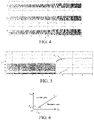
- Fig. 3 shows an incomer-side three-phase current waveform actually measured by a converter in a certain variable frequency starting process, i Na is a-phase current, i Nb is b-phase current, and i Nc is c-phase current.
- Fig. 4 shows an incomer-side three-phase current waveform actually measured by a converter in a certain variable frequency starting process
- i Ma is a-phase current
- i Mb is b-phase current
- i Mc is c-phase current.
- Fig. 5 shows calculation results for data in Fig. 3 and Fig. 4 , wherein I diff and I res are a differential current and a restraint current obtained through calculation according to Formula 9 in the embodiments of the present invention.
- the abscissa I res is the restraint current
- the ordinate I diff is the differential current
- a two-line ratio restraint characteristic curve ABC above the curve is a differential protection action area
- below the curve is a differential protection restraint area
- I op ,0 is a differential current value corresponding to a starting point A
- I res ,0 is a restraint current value corresponding to an inflection point B.
- the abscissa I res is the restraint current
- the ordinate I diff is the differential current
- a variable-slope ratio restraint characteristic curve ABCD above the curve is a differential protection action area
- below the curve is a differential protection restraint area
- I op ,0 is a differential current value corresponding to a starting point A
- K bl 1 is a starting ratio differential slope (the slope of the curve at A point)
- I rated is a rated current of the protected device (which has been converted to a CT secondary value)
- a is a restraint current multiple in the case of a maximum ratio restraint coefficient
- K bl 2 is a maximum ratio differential slope (the slope of the curve at C point)
- a CD segment is a line segment.
- rated power of a pumped storage generator motor is 50 MW, a rated voltage is 10. 5 kV, and a rated power factor is 0.85.
- a configured SFC is as shown in Fig. 1 , an incomer-side bus voltage is 10.5 kV, an incomer transformer T1 is a three-loop transformer with capacity of 4 MVA, a voltage ratio is 10.5 kV/0.7 kV/0.7 kV, and a transformer connection manner is Dd0y1; two rectifier bridges NB1 and NB2 are cascaded on the SFC incomer side, and current ratios of AC-side three-phase current transformers CT2 and CT3 of the rectifier bridges are both 2000A/1A; one inverter bridge MB is on the SFC outgoer side, and a current ratio of an AC-side three-phase current transformer CT4 of the inverter bridge is 2000A/1A; after output of the inverter bridge, a two-loop transformer T2 with capacity of 4 MVA is connected,
- currents on two sides of the SFC by taking an incomer-side current measured by CT2 and an output-side current measured by CT4 as an example, can achieve differential protection according to the method of the embodiments of the present invention.
- an incomer-side current measured by CT3 and an output-side current measured by CT4 can also achieve differential protection.
- a relay protection device samples a secondary side current of a current transformer CT2, to obtain a incomer-side three-phase current (CT current secondary value) data sequence i Na ( n ), i Nb ( n ) and i Nc ( n ); the relay protection device samples a secondary side current of a current transformer CT4, to obtain an outgoer-side three-phase current (CT current secondary value) data sequence i Ma ( n ), i Mb ( n ) and i Mc ( n ).
- the sign n indicates a sampling sequence number
- the subscripts Na, Nb and Nc indicate incomer-side (grid-side) a phase, b phase and c phase
- the subscripts Ma, Mb and Mc indicate outgoer-side a phase
- b phase and c phase W is the length of a sampling data window, and in the domestic relay protection device, W is generally set as 24.
- Fig. 3 shows an incomer-side three-phase current waveform actually measured in a variable frequency starting process of the pumped-storage unit SFC.
- Fig. 4 shows an outgoer-side three-phase current waveform actually measured in a variable frequency starting process of the pumped-storage unit SFC.
- the frequency of the incomer-side three-phase current is kept at a power frequency 50 Hz, while the frequency of the outgoer-side three-phase current ranges greatly from low to high and gradually rises to 50 Hz.
- the former stage is a phase commutation process, in which the current is discontinuous
- the latter stage is a load commutation process, in which the current is continuous.
- digital rectification is respectively performed on the incomer-side (grid-side) three-phase current and the outgoer-side three-phase current.
- a data sequence is obtained according to the following Formula 1 and Formula 2: wherein, or the digital rectification is performed according to Formula 1' and Formula 2', to obtain:
- + indicates a direction in which a current flows out from an upper bridge arm of a rectifier bridge
- - indicates a direction in which the current flows back from a lower bridge arm of the rectifier bridge
- a difference of the equivalent two side currents is calculated, to obtain a transient differential current through calculation according to Formula 5; the equivalent two side currents are averaged, to obtain a transient restraint current through calculation according to Formula 6.
- K1 and K2 in Formula 5 and Formula 6 are current reduction coefficients, and are related to incomer-side and outgoer-side CT current ratios. Generally, reduction is made to the side where the CT ratio is less.
- Method 1 arithmetic method.
- the differential current and the restraint current are:
- Method 2 root-mean-square algorithm.
- the differential current and the restraint current are:
- W is a data window length, which can be set as 0.5-1.0 times the number of sampling points within one power frequency cycle.
- W is the number of sampling points within one power frequency cycle, it is called a full data window; when W is less than the number of sampling points within one power frequency cycle, it is called a short data window.
- the short data window is used, an action speed of the differential protection can be accelerated.
- the number of sampling points within one power frequency cycle of the relay protection device is 24, and at this point, the value of W can be within a range of 12-24.
- I diff + and I res + make up a group of differential current and restraint current, and differential protection can be achieved according to conventional line ratio restraint characteristics (e.g., as shown in Fig. 6 ) or variable-slope ratio restraint characteristics (e.g., as shown in Fig. 7 ).
- I diff - and I res - make up a group of differential current and restraint current
- I diff and I res also can make up a group of differential current and restraint current.
- Fig. 5 shows a result of calculation according to Formula 9 of the embodiments of the present invention. It can be seen that when the pumped storage unit SFC has no fault, the differential current calculated in the embodiments of the present invention is very small, the restraint current is relatively great, and the differential protection can make no action reliably.
- the embodiments of the present invention further correspondingly put forward a relay protection device, wherein the device includes: a sampling unit, a rectifier unit, a first acquisition unit, a second acquisition unit and a differential protection unit; wherein
- the rectifier unit is configured to: obtain an incomer-side input current and an outgoer-side output current which are equivalent according to and wherein
- the rectifier unit is configured to: obtain an incomer-side input current and an outgoer-side output current which are equivalent according to and wherein the sign n indicates a sampling sequence number.
- the first acquisition unit is configured to:
- the second acquisition unit is configured to:
- the second acquisition unit is configured to:
- the differential protection unit is configured to: achieve differential protection according to the differential current and the restraint current based on line ratio restraint characteristics or variable-slope ratio restraint characteristics.
Landscapes
- Engineering & Computer Science (AREA)
- Power Engineering (AREA)
- Emergency Protection Circuit Devices (AREA)
- Rectifiers (AREA)
Description
- Embodiments of the present invention relate to the field of power and electron technologies, and in particular to a differential protection method for current source converter, and a relay protection device.
- For high-power power electronic converters (sometimes called inverters), according to types of output waveforms, converters having independent controllable topology of output voltage waveforms are called voltage source converter or voltage source inverter (VSC or VSI); similarly, converters having independent controllable topology of output current waveforms are called current source converter or current source inverter (CSC or CSI).
- Regarding the discussion about this aspect, reference can be made to Chapter 14 of Power Electronics Handbook ([US] mainly complied by Muhammad H. Rashid, translated by Chen Jianye et al., China Machine Press, 2004).
- Large-capacity CSCs are widely applied to power systems, for example, three-phase full bridge controlled rectifiers of large generator self-shunt excitation systems, pumping mode starting devices of large pumped-storage units, i.e., static frequency converters (SFCs), large gas turbine generator starting devices, i.e., Load Commutated Inverters (LCIs), and converters used by some large traction devices.
- For the large-capacity CSC devices, a relay protection method for reliably and rapidly judging an internal short circuit fault is often required. A ratio restraint characteristic differential protection method (reference can be made to RELAY PROTECTION PRINCIPLE AND APPLICATION OF MAIN ELECTRICAL EQUIPMENT (2nd Edition) compiled by Professor Wang Weijian Tsinghua University, China Electric Power Press, 2002) is a method for judging an internal short circuit fault in power devices widely applied to power systems, which not only has high protection reliability and rapid movement speed, but also can distinguish whether a short circuit fault occurs inside (called internal fault) or outside (called external fault). An incomer side and an outgoer side of a protected device are respectively mounted with a protection-level current transformer (CT), and the past differential protection method needs to measure and calculate power frequency currents of CTs on two sides. However, for the CSC devices applied in the power systems, it is common that an alternating current at a power frequency is input from the incomer side (grid side) and an alternating current at a frequency ranging greatly is output from the other outgoer side, and the past differential protection method cannot be directly applied to occasions where current frequencies on the two sides are different.
- At present, relay protection methods mostly used by the large-capacity CSC devices are: overcurrent protection, overload protection, asymmetrical three phase current protection, current change rate

-
US 2007/041137 A1 relates to an apparatus and method for providing differential protection for a phase angle regulating transformer having a load side and a source side in a three-phase power system. -
WO 2012/113455 A1 discloses a differential protection scheme for converters with a stage for rectifying the AC current signals from both sides. - An objective of the embodiments of the present invention is to provide a differential protection method for current source converter and a relay protection device, to solve the problem to apply a more robust and reliable differential protection method to current source converters.
- The technical solution adopted by the embodiments of the present invention is defined by the method and the apparatus of
claim 1 and 6. - A differential protection method for current source converter, according to the invention, includes:
- sampling, by a relay protection device, secondary side currents of current transformers on two sides of a protected current source converter, to obtain incomer-side three-phase currents iNa , iNb and iNc , and outgoer-side three-phase currents iMa , iMb and iMc ;
- rectifying the incomer-side three-phase currents and the outgoer-side three-phase currents, to obtain an incomer-side input current iN and an outgoer-side output current iM ;
- converting the incomer-side input current and the outgoer-side output current according to a current ratio of the current transformers on the two sides, to acquire a transient differential current idiff and a transient restraint current ires ;
- acquiring a differential current Idiff and a restraint current Ires according to the transient differential current and the transient restraint current; and
- achieving differential protection according to the differential current Idiff and the restraint current Ires .
- According to the invention, the rectifying the incomer-side three-phase currents and the outgoer-side three-phase currents, to obtain an incomer-side input current iN and an outgoer-side output current iM :
using hardware rectification, and using a hardware three-phase rectifier bridge inside the relay protection device, to obtain the rectified incomer-side input current iN and outgoer-side output current iM . - According to the invention, the method includes converting the rectified incomer-side input current and the rectified outgoer-side output current according to a current ratio of the current transformers on the two sides to acquire a transient differential current idiff and a transient restraint current ires. The transient differential current is acquired according to


- Preferably, the acquiring a differential current Idiff and a restraint current Ires according to the transient differential current and the transient restraint current includes:
- according to


- performing arithmetic mean functional transformation to obtain the differential current Idiff and the restraint current Ires , wherein n or k indicates a sampling sequence number, and w is a data window length.
- Preferably, the acquiring a differential current Idiff and a restraint current Ires according to the transient differential current and the transient restraint current includes:
- according to
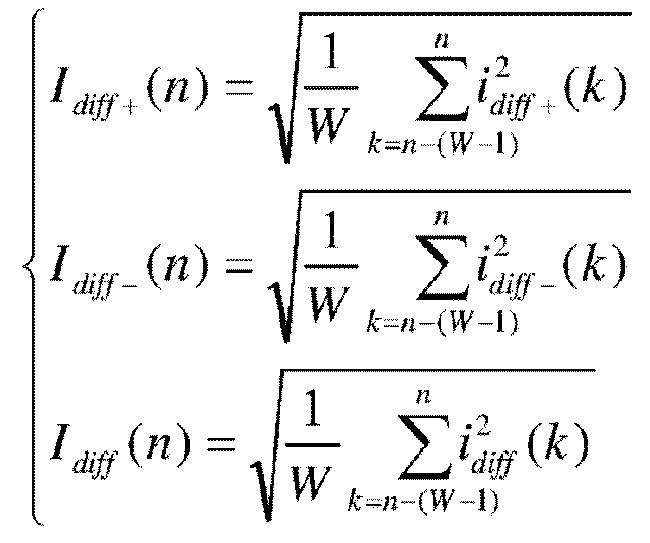

- performing root-mean-square functional transformation to obtain the differential current Idiff and the restraint current Ires , wherein n or k indicates a sampling sequence number, and w is a data window length.
- Preferably, the achieving differential protection according to the differential current Idiff and the restraint current Ires includes:
achieving differential protection according to the differential current and the restraint current based on line ratio restraint characteristics or variable-slope ratio restraint characteristics. - Preferably, I diff+ and I res+ make up a group of differential current and restraint current, Idiff- and I res- make up a group of differential current and restraint current, and Idiff and Ires make up a group of differential current and restraint current.
- A relay protection device, according to the invention, includes:
- a sampling unit, a rectifier unit, a first acquisition unit, a second acquisition unit and a differential protection unit; wherein the sampling unit is configured to sample secondary side currents of current transformers on two sides of a protected current source converter, to obtain incomer-side three-phase currents iNa , iNb and iNc , and outgoer-side three-phase currents iMa , iMb and iMc ;
- the rectifier unit is configured to rectify the incomer-side three-phase currents and the outgoer-side three-phase currents, to obtain an incomer-side input current iN and an outgoer-side output current iM ;
- the first acquisition unit is configured to convert the incomer-side input current and the outgoer-side output current according to a current ratio of the current transformers on the two sides, to acquire a transient differential current idiff and a transient restraint current ires ;
- the second acquisition unit is configured to acquire a differential current Idiff and a restraint current Ires according to the transient differential current and the transient restraint current; and
- the differential protection unit is configured to achieve differential protection according to the differential current Idiff and the restraint current Ires .
- According to the invention, the rectifier unit is configured to:
use hardware rectification, and use a hardware three-phase rectifier bridge inside the relay protection device, to obtain the rectified incomer-side input current iN and outgoer-side output current iM . - According to the invention, the first acquisition unit is configured to:
- acquire the transient differential current according to

- acquire the transient restraint current according to
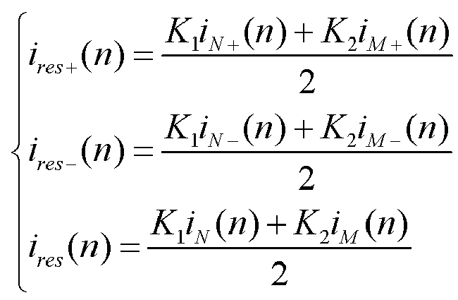
- wherein n indicates a sampling sequence number, K1 and K2 are current reduction coefficients, and when nCT,M ≥nCT,N ,

- Preferably, the second acquisition unit is configured to:
according to

- Preferably, the second acquisition unit is configured to:
according to

- Preferably, the differential protection unit is configured to:
achieve differential protection according to the differential current and the restraint current based on line ratio restraint characteristics or variable-slope ratio restraint characteristics. - Beneficial effects of the embodiments of the present invention are as follows: the problem that the past current converters cannot achieve differential protection as current frequencies on two sides are different is solved, the problem that relay protection of the past current converters cannot distinguish an internal fault from an external fault is solved, and a rapid relay protection method is provided for the current converters, wherein the method has simple secondary circuit connections, facilitates protection setting calculation, and is easy to use.
-
-
Fig. 1 is a schematic view of one current converter differential protection connection according to an embodiment of the present invention; -
Fig. 2 is a schematic view of another current converter differential protection connection according to an embodiment of the present invention; -
Fig. 3 is an incomer-side three-phase current waveform actually measured of a certain example of current converter differential protection according to an embodiment of the present invention; -
Fig. 4 is an outgoer-side three-phase current waveform actually measured of a certain example of current converter differential protection according to an embodiment of the present invention; -
Fig. 5 is a differential current and a restraint current calculated in a certain example of current converter differential protection according to an embodiment of the present invention; -
Fig. 6 is a schematic view of a two-line ratio restraint characteristic diagram of current converter differential protection according to an embodiment of the present invention; and -
Fig. 7 is a schematic view of a variable-slope ratio restraint characteristic diagram of current converter differential protection according to an embodiment of the present invention. - To clearly describe the method of the present invention, specific implementation manners of the present invention are stated herein by taking a SFC of a certain 50 MW pumped storage unit as an example.
- The BUS in
Fig. 1 is a grid incomer-side bus, CB1 is an incomer-side circuit breaker, CB2 is an outgoer-side circuit breaker, T1 is an incomer-side isolation transformer, T2 is an outgoer-side isolation transformer, NB1 and NB2 are incomer-side rectifier bridges (called network bridges), MB is an outgoer-side inverter bridge (called machine bridge), L is a converter DC reactor, G is a generator motor, CT1-CT5 are three-phase current transformers, and a in the figure indicates a relay protection device.Fig. 2 is different fromFig. 1 in that there is no outgoer-side isolation transformer and there is only one group of incomer-side rectifier bridges.Fig. 1 is a schematic view of a common SFC connection, andFig. 2 is a common LCI connection. -
Fig. 3 shows an incomer-side three-phase current waveform actually measured by a converter in a certain variable frequency starting process, iNa is a-phase current, iNb is b-phase current, and iNc is c-phase current. -
Fig. 4 shows an incomer-side three-phase current waveform actually measured by a converter in a certain variable frequency starting process, iMa is a-phase current, iMb is b-phase current, and iMc is c-phase current. -
Fig. 5 shows calculation results for data inFig. 3 andFig. 4 , wherein Idiff and Ires are a differential current and a restraint current obtained through calculation according to Formula 9 in the embodiments of the present invention. - In
Fig. 6 , the abscissa Ires is the restraint current, the ordinate Idiff is the differential current, a two-line ratio restraint characteristic curve ABC, above the curve is a differential protection action area, below the curve is a differential protection restraint area, I op,0 is a differential current value corresponding to a starting point A, and I res,0 is a restraint current value corresponding to an inflection point B. - In
Fig. 7 , the abscissa Ires is the restraint current, the ordinate Idiff is the differential current, a variable-slope ratio restraint characteristic curve ABCD, above the curve is a differential protection action area, below the curve is a differential protection restraint area, I op,0 is a differential current value corresponding to a starting point A, K bl1 is a starting ratio differential slope (the slope of the curve at A point), Irated is a rated current of the protected device (which has been converted to a CT secondary value), a is a restraint current multiple in the case of a maximum ratio restraint coefficient, K bl2 is a maximum ratio differential slope (the slope of the curve at C point), and a CD segment is a line segment. - For example, rated power of a pumped storage generator motor is 50 MW, a rated voltage is 10. 5 kV, and a rated power factor is 0.85. A configured SFC is as shown in
Fig. 1 , an incomer-side bus voltage is 10.5 kV, an incomer transformer T1 is a three-loop transformer with capacity of 4 MVA, a voltage ratio is 10.5 kV/0.7 kV/0.7 kV, and a transformer connection manner is Dd0y1; two rectifier bridges NB1 and NB2 are cascaded on the SFC incomer side, and current ratios of AC-side three-phase current transformers CT2 and CT3 of the rectifier bridges are both 2000A/1A; one inverter bridge MB is on the SFC outgoer side, and a current ratio of an AC-side three-phase current transformer CT4 of the inverter bridge is 2000A/1A; after output of the inverter bridge, a two-loop transformer T2 with capacity of 4 MVA is connected, a voltage ratio is 1.4 kV/10.5 kV, a transformer connection manner is Yd1, and after output of the transformer, the generator motor G is connected. - Herein, currents on two sides of the SFC, by taking an incomer-side current measured by CT2 and an output-side current measured by CT4 as an example, can achieve differential protection according to the method of the embodiments of the present invention. Similarly, an incomer-side current measured by CT3 and an output-side current measured by CT4 can also achieve differential protection.
- Specific steps of the embodiments of the present invention are as follows:
- A relay protection device samples a secondary side current of a current transformer CT2, to obtain a incomer-side three-phase current (CT current secondary value) data sequence iNa (n), iNb (n) and iNc (n); the relay protection device samples a secondary side current of a current transformer CT4, to obtain an outgoer-side three-phase current (CT current secondary value) data sequence iMa (n), iMb (n) and iMc (n). The sign n indicates a sampling sequence number, the subscripts Na, Nb and Nc indicate incomer-side (grid-side) a phase, b phase and c phase, the subscripts Ma, Mb and Mc indicate outgoer-side a phase, b phase and c phase. W is the length of a sampling data window, and in the domestic relay protection device, W is generally set as 24.
-
Fig. 3 shows an incomer-side three-phase current waveform actually measured in a variable frequency starting process of the pumped-storage unit SFC.Fig. 4 shows an outgoer-side three-phase current waveform actually measured in a variable frequency starting process of the pumped-storage unit SFC. In the variable frequency starting process, the frequency of the incomer-side three-phase current is kept at a power frequency 50 Hz, while the frequency of the outgoer-side three-phase current ranges greatly from low to high and gradually rises to 50 Hz. In the variable frequency starting process, the former stage is a phase commutation process, in which the current is discontinuous, and the latter stage is a load commutation process, in which the current is continuous. - It should be noted that there are two rectification methods:
- (I) Hardware rectification, that is, a hardware three-phase rectifier bridge is used inside the relay protection device, to obtain the rectified incomer-side input current iN and outgoer-side output current iM which are equivalent; and
- (II) Software rectification, also called digital rectification, that is, first values of the incomer-side three-phase current and the outgoer-side three-phase current are obtained through sampling, and then through a calculation method, an incomer-side input current iN and an outgoer-side output current iM which are equivalent are obtained.
- In the embodiments of the present invention, digital rectification is respectively performed on the incomer-side (grid-side) three-phase current and the outgoer-side three-phase current. Through the rectification method, a data sequence is obtained according to the following
Formula 1 and Formula 2:



- After the digital rectification, two side currents are converted to fluctuant DCs. When there is no short circuit fault inside the SFC, a DC flowing into the SFC is approximately equal to that flowing out of the SFC, and when there is a short circuit fault inside the SFC, inflow and outflow are not equal, and an evident differential current will be generated.
- It should be noted that in the embodiments of the present invention, + indicates a direction in which a current flows out from an upper bridge arm of a rectifier bridge, and - indicates a direction in which the current flows back from a lower bridge arm of the rectifier bridge.
- A difference of the equivalent two side currents is calculated, to obtain a transient differential current through calculation according to
Formula 5; the equivalent two side currents are averaged, to obtain a transient restraint current through calculation according to Formula 6.

- K1 and K2 in
Formula 5 and Formula 6 are current reduction coefficients, and are related to incomer-side and outgoer-side CT current ratios. Generally, reduction is made to the side where the CT ratio is less. The incomer-side CT current ratio is n CT,N = 2000A/1A, and the outgoer-side CT current ratio is n CT,M = 2000A/1A. Referring to Formula 7 above, the current reduction coefficient is: K 1 = K 2 = 1. - There are two methods for calculating a differential current and a restraint current.
- Method 1: arithmetic method. The differential current and the restraint current are:

- Method 2: root-mean-square algorithm. The differential current and the restraint current are:

- In Formula 9 and
Formula 10, W is a data window length, which can be set as 0.5-1.0 times the number of sampling points within one power frequency cycle. When W is the number of sampling points within one power frequency cycle, it is called a full data window; when W is less than the number of sampling points within one power frequency cycle, it is called a short data window. When the short data window is used, an action speed of the differential protection can be accelerated. Generally, the number of sampling points within one power frequency cycle of the relay protection device is 24, and at this point, the value of W can be within a range of 12-24. - Whether Formula 9 or
Formula 10 is used for calculation, I diff+ and I res+ make up a group of differential current and restraint current, and differential protection can be achieved according to conventional line ratio restraint characteristics (e.g., as shown inFig. 6 ) or variable-slope ratio restraint characteristics (e.g., as shown inFig. 7 ). Similarly, I diff- and I res- make up a group of differential current and restraint current, and Idiff and Ires also can make up a group of differential current and restraint current. -
Fig. 5 shows a result of calculation according to Formula 9 of the embodiments of the present invention. It can be seen that when the pumped storage unit SFC has no fault, the differential current calculated in the embodiments of the present invention is very small, the restraint current is relatively great, and the differential protection can make no action reliably. - For a differential fixed value setting method, reference can be made to DL/T684-2012 LARGE GENERATOR TRANSFORMER RELAY PROTECTION SETTING CALCULATION GUIDE RULE or POWER PLANT RELAY PROTECTION SETTING CALCULATION AND OPERATION TECHNOLOGY (compiled by Xu Zhengya, China WaterPower Press, 2009).
- The embodiments of the present invention further correspondingly put forward a relay protection device, wherein the device includes: a sampling unit, a rectifier unit, a first acquisition unit, a second acquisition unit and a differential protection unit; wherein
- the sampling unit is configured to sample secondary side currents of current transformers on two sides of a protected current source converter, to obtain incomer-side three-phase currents iNa , iNb and iNc , and outgoer-side three-phase currents iMa , iMb and iMc ;
- the rectifier unit is configured to rectify the incomer-side three-phase currents and the outgoer-side three-phase currents, to obtain an incomer-side input current iN and an outgoer-side output current iM which are equivalent;
- the first acquisition unit is configured to convert the incomer-side input current and the outgoer-side output current according to a current ratio of the current transformers on the two sides, to acquire a transient differential current idiff and a transient restraint current ires ;
- the second acquisition unit is configured to acquire a differential current idiff and a restraint current Ires according to the transient differential current and the transient restraint current; and
- the differential protection unit is configured to achieve differential protection according to the differential current idiff and the restraint current Ires .
- Optionally, the rectifier unit is configured to:
obtain an incomer-side input current and an outgoer-side output current which are equivalent according to



- Optionally, the rectifier unit is configured to:
obtain an incomer-side input current and an outgoer-side output current which are equivalent according to

- Optionally, the first acquisition unit is configured to:
- acquire the transient differential current according to

- acquire the transient restraint current according to

- wherein n indicates a sampling sequence number, K1 and K2 are current reduction coefficients, and when n CT,M ≥n CT,N ,

- Optionally, the second acquisition unit is configured to:
- according to


- perform arithmetic mean functional transformation to obtain the differential current idiff and the restraint current Ires , wherein n or k indicates a sampling sequence number, and w is a data window length.
- Optionally, the second acquisition unit is configured to:
- according to


- perform root-mean-square functional transformation to obtain the differential current idiff and the restraint current, wherein n or k indicates a sampling sequence number, and w is a data window length.
- Optionally, the differential protection unit is configured to:
achieve differential protection according to the differential current and the restraint current based on line ratio restraint characteristics or variable-slope ratio restraint characteristics. - The above embodiments merely describe the technical thought of the present invention, but cannot be used to limit the protection scope of the present invention; any equivalent replacement or variation made on the basis of the technical solution according to the technical thought put forward in the present invention does not go beyond the protection scope of the present invention.
Claims (8)
- A differential protection method applied to a current source converter, wherein the method comprises:sampling, by a relay protection device, secondary side currents of current transformers on two sides of a protected current source converter, to obtain incomer-side three-phase currents iNa , iNb and iNc , and outgoer-side three-phase currents iMa , iMb and iMc ;rectifying the incomer-side three-phase currents and the outgoer-side three-phase currents, to obtain a rectified incomer-side input current iN and a rectified outgoer-side output current iM ; wherein the step of rectifying comprises:using a hardware three-phase rectifier bridge inside the relay protection device, to obtain the rectified incomer-side input current iN and rectified outgoer-side output current iM ;converting the rectified incomer-side input current and the rectified outgoer-side output current according to a current ratio of the current transformers on the two sides, to acquire a transient differential current idiff and a transient restraint current ires ; andacquiring the transient differential current idiff according to
 acquiring the transient restraint current ires according to
 wherein the index + of the rectified currents indicates that the current flows out from an upper arm of the rectifying bridge and the index - indicates that the current flows back from a lower bridge arm of the rectifying bridge; n indicates a sampling sequence number, K1 and K2 are current reduction coefficients, and when n CT,M ≥n CT,N ,
 wherein n CT,N is the current ratio of the incomer-side current transformer and n CT,M is the current ration of the outgoer-side current transformer;acquiring a differential current Idiff and a restraint current Ires according to the transient differential current and the transient restraint current; andachieving differential protection according to the differential current Idiff and the restraint current Ires .
 - The differential protection method according to claim 1, wherein the acquiring a differential current Idiff and a restraint current Ires according to the transient differential current and the transient restraint current comprises:according to

 performing arithmetic mean functional transformation to obtain the differential current Idiff and the restraint current Ires , wherein n or k indicates a sampling sequence number, and w is a data window length.
 - The differential protection method according to claim 1, wherein the acquiring a differential current Idiff and a restraint current Ires according to the transient differential current and the transient restraint current comprises:according to

 performing root-mean-square functional transformation to obtain the differential current Idiff and the restraint current, wherein n or k indicates a sampling sequence number, and w is a data window length.
 - The differential protection method according to any one of claims 1 to 3, wherein the achieving differential protection according to the differential current Idiff and the restraint current Ires comprises:
achieving differential protection according to the differential current and the restraint current based on line ratio restraint characteristics or variable-slope ratio restraint characteristics. - The differential protection method according to claim 2 or 3, wherein I diff+ and I res+ make up a group of differential current and restraint current, I diff- and I res-make up a group of differential current and restraint current, and Idiff and Ires make up a group of differential current and restraint current.
- A relay protection device for a current source converter, wherein the device comprises: a sampling unit, a rectifier unit, a first acquisition unit, a second acquisition unit and a differential protection unit; whereinthe sampling unit is configured to sample secondary side currents of current transformers on two sides of a protected current source converter, to obtain incomer-side three-phase currents iNa , iNb and iNc , and outgoer-side three-phase currents iMa , iMb and iMc ;the rectifier unit is configured to rectify the incomer-side three-phase currents and the outgoer-side three-phase currents, to obtain a rectified incomer-side input current iN and a rectified outgoer-side output current iM ; wherein the rectifier unit is a hardware three-phase rectifier bridge inside the relay protection device, to obtain the rectified incomer-side input current iN and rectified outgoer-side output current iM ;the first acquisition unit is configured to convert the rectified incomer-side input current and the rectified outgoer-side output current according to a current ratio of the current transformers on the two sides, to acquire a transient differential current idiff and a transient restraint current ires ; wherein the acquisition unit is further configured to acquire the transient differential current idiff according to
 acquiring the transient restraint current ires according to
 wherein n CT,N is the current ratio of the incomer-side current transformer and n CT,M is the current ration of the outgoer-side current transformer;the second acquisition unit is configured to acquire a differential current Idiff and a restraint current Ires according to the transient differential current and the transient restraint current; andthe differential protection unit is configured to achieve differential protection according to the differential current Idiff and the restraint current Ires .
 - The relay protection device according to claim 6, wherein the second acquisition unit is configured to perform arithmetic mean functional transformation to obtain the differential current Idiff and the restraint current Iresaccording to

 n or k indicates a sampling sequence number, and w is a data window length ; orthe second acquisition unit is configured to perform root-mean-square functional transformation to obtain the differential current Idiff and the restraint current Ires according to
 wherein n or k indicates a sampling sequence number, and w is a data window length.
 - The relay protection device according to any one of claims 6 or 7, wherein the differential protection unit is configured to:
achieve differential protection according to the differential current and the restraint current based on line ratio restraint characteristics or variable-slope ratio restraint characteristics.
Applications Claiming Priority (2)
| Application Number | Priority Date | Filing Date | Title |
|---|---|---|---|
| CN201310210288.0A CN104218543B (en) | 2013-05-30 | 2013-05-30 | Current source type converter differential protecting method |
| PCT/CN2014/075267 WO2014190814A1 (en) | 2013-05-30 | 2014-04-14 | Differential protection method for current source converter, and relay protection device |
Publications (3)
| Publication Number | Publication Date |
|---|---|
| EP3007294A1 EP3007294A1 (en) | 2016-04-13 |
| EP3007294A4 EP3007294A4 (en) | 2017-01-25 |
| EP3007294B1 true EP3007294B1 (en) | 2022-04-13 |
Family
ID=51987972
Family Applications (1)
| Application Number | Title | Priority Date | Filing Date |
|---|---|---|---|
| EP14804991.9A Active EP3007294B1 (en) | 2013-05-30 | 2014-04-14 | Differential protection method for current source converter, and relay protection device |
Country Status (8)
| Country | Link |
|---|---|
| US (1) | US9584007B2 (en) |
| EP (1) | EP3007294B1 (en) |
| JP (1) | JP6396999B2 (en) |
| KR (1) | KR102010117B1 (en) |
| CN (1) | CN104218543B (en) |
| ES (1) | ES2917880T3 (en) |
| RU (1) | RU2649324C2 (en) |
| WO (1) | WO2014190814A1 (en) |
Families Citing this family (13)
| Publication number | Priority date | Publication date | Assignee | Title |
|---|---|---|---|---|
| CN105186452B (en) * | 2015-09-10 | 2017-10-31 | 南京国电南自电网自动化有限公司 | A kind of phase-shifting transformer differential protection implementation method |
| CN105353271B (en) * | 2015-11-03 | 2017-12-12 | 云南电网有限责任公司电力科学研究院 | A kind of current differential protection saturation method of discrimination |
| CN105514957B (en) * | 2016-01-28 | 2017-12-22 | 南京南瑞继保电气有限公司 | One kind mixing back-to-back DC power transmission system and trend reversion control method |
| EP3622609A4 (en) * | 2017-05-10 | 2021-05-12 | North Carolina State University | MODULAR MEDIUM VOLTAGE FAST CHARGERS |
| CN107612403B (en) * | 2017-10-09 | 2019-07-26 | 山东大学 | The four sample modulation method of monocycle of H7 current source type converter |
| CN108258665B (en) * | 2018-01-15 | 2019-08-09 | 清华大学 | Parallel reactance compensation line traveling wave differential protection method, device, equipment and medium |
| CN108306263B (en) * | 2018-01-15 | 2019-09-20 | 清华大学 | Power line traveling wave differential protection method, device, equipment and medium |
| CN108270207B (en) * | 2018-01-15 | 2019-10-18 | 清华大学 | Method, device, equipment and medium for traveling wave differential protection of series capacitor compensation line |
| JP7117963B2 (en) * | 2018-10-02 | 2022-08-15 | 三菱電機株式会社 | Protective relay device |
| CN114744599B (en) * | 2022-04-27 | 2025-02-18 | 国网浙江省电力有限公司电力科学研究院 | Adaptive low-frequency transmission line current differential protection method and system |
| CN115313305B (en) * | 2022-08-12 | 2024-09-10 | 三峡大学 | Current differential protection method based on local uniform compression and remote restoration of sampled values |
| CN115513907B (en) * | 2022-09-13 | 2025-06-13 | 许继电气股份有限公司 | A M3C frequency converter differential protection method and system |
| CN118937850B (en) * | 2024-08-13 | 2025-04-11 | 国网江苏省电力有限公司淮安供电分公司 | A portable relay protection trip matrix test system and method |
Family Cites Families (25)
| Publication number | Priority date | Publication date | Assignee | Title |
|---|---|---|---|---|
| JPS4725926U (en) * | 1971-04-20 | 1972-11-24 | ||
| US4295175A (en) * | 1980-04-21 | 1981-10-13 | General Electric Company | Pilot wire relay protection system for electrical distribution networks |
| US4475150A (en) * | 1982-04-28 | 1984-10-02 | General Electric Company | Coordinated load commutated inverter protection system |
| SU1156213A1 (en) * | 1983-11-24 | 1985-05-15 | Челябинский Политехнический Институт Им.Ленинского Комсомола | Rectifier with protection against short-circuit currents |
| JPH01170318A (en) * | 1987-12-23 | 1989-07-05 | Hitachi Ltd | Ratio differential relay |
| CA2071397A1 (en) * | 1991-09-05 | 1993-03-06 | John F. Kral | Control apparatus for detecting and commutating fault currents in an alternator-fed dc power supply |
| JP2001025154A (en) * | 1999-07-07 | 2001-01-26 | Toshiba Corp | Transformer protection relay |
| WO2002093710A1 (en) * | 2001-05-17 | 2002-11-21 | Yong-Cheol Kang | Relaying method for protecting a transformer using a difference of current |
| JP4112930B2 (en) * | 2002-09-04 | 2008-07-02 | 東芝三菱電機産業システム株式会社 | Inverter device |
| CN1295834C (en) * | 2003-08-08 | 2007-01-17 | 国电南京自动化股份有限公司 | Judging method for heavy saturation of current transformer by time-difference method for relay protection |
| SE0303615D0 (en) * | 2003-12-31 | 2003-12-31 | Abb Ab | Method and device for Fault Detection in Transformers |
| JP4759968B2 (en) * | 2004-10-04 | 2011-08-31 | ダイキン工業株式会社 | Method and apparatus for protecting PWM rectifier circuit |
| US7319576B2 (en) * | 2005-08-18 | 2008-01-15 | Schweitzer Engineering Labortories, Inc. | Apparatus and method for providing differential protection for a phase angle regulating transformer in a power system |
| CN101764394B (en) * | 2009-11-24 | 2012-06-20 | 国电南瑞科技股份有限公司 | Direct current differential protection method of rectification unit |
| WO2012113455A1 (en) * | 2011-02-25 | 2012-08-30 | Abb Technology Ag | A method for obtaining an instantaneous direct current value, and control device |
| CN103947096B (en) * | 2011-10-21 | 2016-09-21 | Abb研究有限公司 | Method and system for detecting failed rectifiers in AC/DC converters |
| CN102403699B (en) * | 2011-11-08 | 2014-04-23 | 西安交通大学 | Self-adaptive current differential protection method for direct-current lines |
| CN103208960A (en) * | 2012-01-16 | 2013-07-17 | 台达电子企业管理(上海)有限公司 | Excitation control circuit and electric excitation wind power system thereof |
| WO2013159306A1 (en) * | 2012-04-26 | 2013-10-31 | General Electric Company | Power converter system, damping system, and method of operating power converter system |
| EP2680385B1 (en) * | 2012-06-29 | 2016-04-20 | ABB Technology AG | Differential protection in electrical power networks |
| CN103580494B (en) * | 2012-07-19 | 2016-04-20 | 台达电子工业股份有限公司 | Converter system |
| CN103683195B (en) * | 2012-09-11 | 2016-12-21 | 南京南瑞继保电气有限公司 | Frequency-conversiondifferential differential protection method for output transformer of SFC system |
| JP6018934B2 (en) * | 2013-01-25 | 2016-11-02 | 株式会社日立製作所 | Power converter |
| US9331487B2 (en) * | 2013-03-14 | 2016-05-03 | Rockwell Automation Technologies, Inc. | Method and apparatus for islanding detection for grid tie converters |
| WO2015187636A2 (en) * | 2014-06-03 | 2015-12-10 | Cooper Technologies Company | Power transformer inrush current detector |
-
2013
- 2013-05-30 CN CN201310210288.0A patent/CN104218543B/en active Active
-
2014
- 2014-04-14 US US14/894,944 patent/US9584007B2/en active Active
- 2014-04-14 JP JP2016515618A patent/JP6396999B2/en active Active
- 2014-04-14 ES ES14804991T patent/ES2917880T3/en active Active
- 2014-04-14 EP EP14804991.9A patent/EP3007294B1/en active Active
- 2014-04-14 RU RU2015156143A patent/RU2649324C2/en active
- 2014-04-14 WO PCT/CN2014/075267 patent/WO2014190814A1/en not_active Ceased
- 2014-04-14 KR KR1020157035281A patent/KR102010117B1/en active Active
Also Published As
| Publication number | Publication date |
|---|---|
| KR102010117B1 (en) | 2019-08-12 |
| JP6396999B2 (en) | 2018-09-26 |
| RU2649324C2 (en) | 2018-04-02 |
| JP2016526370A (en) | 2016-09-01 |
| KR20160026876A (en) | 2016-03-09 |
| RU2015156143A (en) | 2017-07-06 |
| ES2917880T3 (en) | 2022-07-12 |
| CN104218543B (en) | 2016-12-28 |
| US20160118877A1 (en) | 2016-04-28 |
| EP3007294A1 (en) | 2016-04-13 |
| US9584007B2 (en) | 2017-02-28 |
| WO2014190814A1 (en) | 2014-12-04 |
| CN104218543A (en) | 2014-12-17 |
| EP3007294A4 (en) | 2017-01-25 |
Similar Documents
| Publication | Publication Date | Title |
|---|---|---|
| US9584007B2 (en) | Current source converter differential protection method and relay protection device | |
| US9331487B2 (en) | Method and apparatus for islanding detection for grid tie converters | |
| EP3886288A1 (en) | Offshore wind farm high-frequency uncontrolled rectification direct-current electric power transmission system | |
| Feltes et al. | Enhanced fault ride-through method for wind farms connected to the grid through VSC-based HVDC transmission | |
| EP2481139B1 (en) | Method for controlling a power converter in a wind turbine generator | |
| US20120101643A1 (en) | Reactive power controller for controlling reactive power in a wind farm | |
| CN104283235B (en) | converter of wind generating set and control method and device of converter | |
| US20170250533A1 (en) | Method and Apparatus for Eliminating Harmonic Components and Obtaining a Uniform Power Factor in Alternating Current-Direct Current and Direct Current-Alternating Current Converters | |
| CN102651548B (en) | Voltage fluctuation suppression method for DC (Direct Current) bus of converter at wind power generation system network side | |
| KR101410744B1 (en) | Limitation method of the current and regeneration power reference using the grid-side converter capacity connected with utility grid | |
| Iov et al. | Grid code compliance of grid-side converter in wind turbine systems | |
| Leng et al. | Smart grid connection of an induction motor using a three-phase floating h-bridge system as a series compensator | |
| CN104699996A (en) | Electric system asymmetric short circuit power frequency electric quantity calculation method based on double-fed induction wind generation set equivalence | |
| CN104967346B (en) | A kind of space vector suppressing method of three-level photovoltaic grid-connected inverter common-mode voltage | |
| Abdollahi | Induction motor drive based on direct torque controlled used multi-pulse AC-DC rectifier | |
| Wu et al. | Adaptability of traditional transformer protection in offshore low-frequency wind power systems | |
| CN119231575B (en) | System and method for inhibiting impact of subsynchronous oscillation of photovoltaic power station on power grid | |
| CN119253616A (en) | Method and device for suppressing transient overvoltage after DC commutation failure | |
| Das et al. | An investigation of harmonics in grid connected DFIG-WT experiencing transmission faults | |
| Zhu et al. | Enhanced short-circuit capacity of grid-forming modular multilevel converters with oval-shaped current limiters | |
| Wang et al. | Short-circuit field tests of Shandong Rongcheng wind farms and measured data analysis | |
| Nguyen-Mau et al. | HVDC application for enhancing power system stability | |
| ČERNELIČ et al. | Control for Grid Connected Small Wind Turbine System | |
| Chen et al. | A new method to improve the LVRT of DFIG based on the current compensation | |
| Moraes et al. | Synchronous compensation versus capacitive compensation for reactive power in industrial systems subjected to harmonic distortion |
Legal Events
| Date | Code | Title | Description |
|---|---|---|---|
| PUAI | Public reference made under article 153(3) epc to a published international application that has entered the european phase |
Free format text: ORIGINAL CODE: 0009012 |
|
| 17P | Request for examination filed |
Effective date: 20151211 |
|
| AK | Designated contracting states |
Kind code of ref document: A1 Designated state(s): AL AT BE BG CH CY CZ DE DK EE ES FI FR GB GR HR HU IE IS IT LI LT LU LV MC MK MT NL NO PL PT RO RS SE SI SK SM TR |
|
| AX | Request for extension of the european patent |
Extension state: BA ME |
|
| DAX | Request for extension of the european patent (deleted) | ||
| A4 | Supplementary search report drawn up and despatched |
Effective date: 20170103 |
|
| RIC1 | Information provided on ipc code assigned before grant |
Ipc: H02H 3/30 20060101AFI20161221BHEP Ipc: H02M 7/04 20060101ALI20161221BHEP Ipc: H02H 7/12 20060101ALI20161221BHEP Ipc: H02M 1/32 20070101ALI20161221BHEP |
|
| STAA | Information on the status of an ep patent application or granted ep patent |
Free format text: STATUS: EXAMINATION IS IN PROGRESS |
|
| 17Q | First examination report despatched |
Effective date: 20200731 |
|
| REG | Reference to a national code |
Ref country code: DE Ref legal event code: R079 Ref document number: 602014083245 Country of ref document: DE Free format text: PREVIOUS MAIN CLASS: H02H0007260000 Ipc: H02H0003340000 |
|
| GRAP | Despatch of communication of intention to grant a patent |
Free format text: ORIGINAL CODE: EPIDOSNIGR1 |
|
| STAA | Information on the status of an ep patent application or granted ep patent |
Free format text: STATUS: GRANT OF PATENT IS INTENDED |
|
| RIC1 | Information provided on ipc code assigned before grant |
Ipc: H02H 7/12 20060101ALI20211014BHEP Ipc: H02H 3/30 20060101ALI20211014BHEP Ipc: H02H 3/34 20060101AFI20211014BHEP |
|
| INTG | Intention to grant announced |
Effective date: 20211103 |
|
| GRAS | Grant fee paid |
Free format text: ORIGINAL CODE: EPIDOSNIGR3 |
|
| GRAA | (expected) grant |
Free format text: ORIGINAL CODE: 0009210 |
|
| STAA | Information on the status of an ep patent application or granted ep patent |
Free format text: STATUS: THE PATENT HAS BEEN GRANTED |
|
| AK | Designated contracting states |
Kind code of ref document: B1 Designated state(s): AL AT BE BG CH CY CZ DE DK EE ES FI FR GB GR HR HU IE IS IT LI LT LU LV MC MK MT NL NO PL PT RO RS SE SI SK SM TR |
|
| REG | Reference to a national code |
Ref country code: GB Ref legal event code: FG4D |
|
| REG | Reference to a national code |
Ref country code: CH Ref legal event code: EP |
|
| REG | Reference to a national code |
Ref country code: DE Ref legal event code: R096 Ref document number: 602014083245 Country of ref document: DE |
|
| REG | Reference to a national code |
Ref country code: IE Ref legal event code: FG4D |
|
| REG | Reference to a national code |
Ref country code: AT Ref legal event code: REF Ref document number: 1484149 Country of ref document: AT Kind code of ref document: T Effective date: 20220515 |
|
| REG | Reference to a national code |
Ref country code: ES Ref legal event code: FG2A Ref document number: 2917880 Country of ref document: ES Kind code of ref document: T3 Effective date: 20220712 |
|
| REG | Reference to a national code |
Ref country code: LT Ref legal event code: MG9D |
|
| REG | Reference to a national code |
Ref country code: NL Ref legal event code: MP Effective date: 20220413 |
|
| REG | Reference to a national code |
Ref country code: AT Ref legal event code: MK05 Ref document number: 1484149 Country of ref document: AT Kind code of ref document: T Effective date: 20220413 |
|
| PG25 | Lapsed in a contracting state [announced via postgrant information from national office to epo] |
Ref country code: NL Free format text: LAPSE BECAUSE OF FAILURE TO SUBMIT A TRANSLATION OF THE DESCRIPTION OR TO PAY THE FEE WITHIN THE PRESCRIBED TIME-LIMIT Effective date: 20220413 |
|
| PG25 | Lapsed in a contracting state [announced via postgrant information from national office to epo] |
Ref country code: SE Free format text: LAPSE BECAUSE OF FAILURE TO SUBMIT A TRANSLATION OF THE DESCRIPTION OR TO PAY THE FEE WITHIN THE PRESCRIBED TIME-LIMIT Effective date: 20220413 Ref country code: PT Free format text: LAPSE BECAUSE OF FAILURE TO SUBMIT A TRANSLATION OF THE DESCRIPTION OR TO PAY THE FEE WITHIN THE PRESCRIBED TIME-LIMIT Effective date: 20220816 Ref country code: NO Free format text: LAPSE BECAUSE OF FAILURE TO SUBMIT A TRANSLATION OF THE DESCRIPTION OR TO PAY THE FEE WITHIN THE PRESCRIBED TIME-LIMIT Effective date: 20220713 Ref country code: LT Free format text: LAPSE BECAUSE OF FAILURE TO SUBMIT A TRANSLATION OF THE DESCRIPTION OR TO PAY THE FEE WITHIN THE PRESCRIBED TIME-LIMIT Effective date: 20220413 Ref country code: HR Free format text: LAPSE BECAUSE OF FAILURE TO SUBMIT A TRANSLATION OF THE DESCRIPTION OR TO PAY THE FEE WITHIN THE PRESCRIBED TIME-LIMIT Effective date: 20220413 Ref country code: GR Free format text: LAPSE BECAUSE OF FAILURE TO SUBMIT A TRANSLATION OF THE DESCRIPTION OR TO PAY THE FEE WITHIN THE PRESCRIBED TIME-LIMIT Effective date: 20220714 Ref country code: FI Free format text: LAPSE BECAUSE OF FAILURE TO SUBMIT A TRANSLATION OF THE DESCRIPTION OR TO PAY THE FEE WITHIN THE PRESCRIBED TIME-LIMIT Effective date: 20220413 Ref country code: BG Free format text: LAPSE BECAUSE OF FAILURE TO SUBMIT A TRANSLATION OF THE DESCRIPTION OR TO PAY THE FEE WITHIN THE PRESCRIBED TIME-LIMIT Effective date: 20220713 Ref country code: AT Free format text: LAPSE BECAUSE OF FAILURE TO SUBMIT A TRANSLATION OF THE DESCRIPTION OR TO PAY THE FEE WITHIN THE PRESCRIBED TIME-LIMIT Effective date: 20220413 |
|
| REG | Reference to a national code |
Ref country code: DE Ref legal event code: R119 Ref document number: 602014083245 Country of ref document: DE |
|
| PG25 | Lapsed in a contracting state [announced via postgrant information from national office to epo] |
Ref country code: RS Free format text: LAPSE BECAUSE OF FAILURE TO SUBMIT A TRANSLATION OF THE DESCRIPTION OR TO PAY THE FEE WITHIN THE PRESCRIBED TIME-LIMIT Effective date: 20220413 Ref country code: PL Free format text: LAPSE BECAUSE OF FAILURE TO SUBMIT A TRANSLATION OF THE DESCRIPTION OR TO PAY THE FEE WITHIN THE PRESCRIBED TIME-LIMIT Effective date: 20220413 Ref country code: LV Free format text: LAPSE BECAUSE OF FAILURE TO SUBMIT A TRANSLATION OF THE DESCRIPTION OR TO PAY THE FEE WITHIN THE PRESCRIBED TIME-LIMIT Effective date: 20220413 Ref country code: IS Free format text: LAPSE BECAUSE OF FAILURE TO SUBMIT A TRANSLATION OF THE DESCRIPTION OR TO PAY THE FEE WITHIN THE PRESCRIBED TIME-LIMIT Effective date: 20220813 |
|
| REG | Reference to a national code |
Ref country code: CH Ref legal event code: PL |
|
| REG | Reference to a national code |
Ref country code: BE Ref legal event code: MM Effective date: 20220430 |
|
| PG25 | Lapsed in a contracting state [announced via postgrant information from national office to epo] |
Ref country code: SM Free format text: LAPSE BECAUSE OF FAILURE TO SUBMIT A TRANSLATION OF THE DESCRIPTION OR TO PAY THE FEE WITHIN THE PRESCRIBED TIME-LIMIT Effective date: 20220413 Ref country code: SK Free format text: LAPSE BECAUSE OF FAILURE TO SUBMIT A TRANSLATION OF THE DESCRIPTION OR TO PAY THE FEE WITHIN THE PRESCRIBED TIME-LIMIT Effective date: 20220413 Ref country code: RO Free format text: LAPSE BECAUSE OF FAILURE TO SUBMIT A TRANSLATION OF THE DESCRIPTION OR TO PAY THE FEE WITHIN THE PRESCRIBED TIME-LIMIT Effective date: 20220413 Ref country code: MC Free format text: LAPSE BECAUSE OF FAILURE TO SUBMIT A TRANSLATION OF THE DESCRIPTION OR TO PAY THE FEE WITHIN THE PRESCRIBED TIME-LIMIT Effective date: 20220413 Ref country code: LU Free format text: LAPSE BECAUSE OF NON-PAYMENT OF DUE FEES Effective date: 20220414 Ref country code: LI Free format text: LAPSE BECAUSE OF NON-PAYMENT OF DUE FEES Effective date: 20220430 Ref country code: EE Free format text: LAPSE BECAUSE OF FAILURE TO SUBMIT A TRANSLATION OF THE DESCRIPTION OR TO PAY THE FEE WITHIN THE PRESCRIBED TIME-LIMIT Effective date: 20220413 Ref country code: DK Free format text: LAPSE BECAUSE OF FAILURE TO SUBMIT A TRANSLATION OF THE DESCRIPTION OR TO PAY THE FEE WITHIN THE PRESCRIBED TIME-LIMIT Effective date: 20220413 Ref country code: DE Free format text: LAPSE BECAUSE OF NON-PAYMENT OF DUE FEES Effective date: 20221103 Ref country code: CZ Free format text: LAPSE BECAUSE OF FAILURE TO SUBMIT A TRANSLATION OF THE DESCRIPTION OR TO PAY THE FEE WITHIN THE PRESCRIBED TIME-LIMIT Effective date: 20220413 Ref country code: CH Free format text: LAPSE BECAUSE OF NON-PAYMENT OF DUE FEES Effective date: 20220430 |
|
| PLBE | No opposition filed within time limit |
Free format text: ORIGINAL CODE: 0009261 |
|
| STAA | Information on the status of an ep patent application or granted ep patent |
Free format text: STATUS: NO OPPOSITION FILED WITHIN TIME LIMIT |
|
| PG25 | Lapsed in a contracting state [announced via postgrant information from national office to epo] |
Ref country code: BE Free format text: LAPSE BECAUSE OF NON-PAYMENT OF DUE FEES Effective date: 20220430 |
|
| 26N | No opposition filed |
Effective date: 20230116 |
|
| GBPC | Gb: european patent ceased through non-payment of renewal fee |
Effective date: 20220713 |
|
| PG25 | Lapsed in a contracting state [announced via postgrant information from national office to epo] |
Ref country code: AL Free format text: LAPSE BECAUSE OF FAILURE TO SUBMIT A TRANSLATION OF THE DESCRIPTION OR TO PAY THE FEE WITHIN THE PRESCRIBED TIME-LIMIT Effective date: 20220413 |
|
| PG25 | Lapsed in a contracting state [announced via postgrant information from national office to epo] |
Ref country code: IE Free format text: LAPSE BECAUSE OF NON-PAYMENT OF DUE FEES Effective date: 20220414 Ref country code: FR Free format text: LAPSE BECAUSE OF NON-PAYMENT OF DUE FEES Effective date: 20220613 |
|
| PG25 | Lapsed in a contracting state [announced via postgrant information from national office to epo] |
Ref country code: SI Free format text: LAPSE BECAUSE OF FAILURE TO SUBMIT A TRANSLATION OF THE DESCRIPTION OR TO PAY THE FEE WITHIN THE PRESCRIBED TIME-LIMIT Effective date: 20220413 Ref country code: GB Free format text: LAPSE BECAUSE OF NON-PAYMENT OF DUE FEES Effective date: 20220713 |
|
| PG25 | Lapsed in a contracting state [announced via postgrant information from national office to epo] |
Ref country code: HU Free format text: LAPSE BECAUSE OF FAILURE TO SUBMIT A TRANSLATION OF THE DESCRIPTION OR TO PAY THE FEE WITHIN THE PRESCRIBED TIME-LIMIT; INVALID AB INITIO Effective date: 20140414 |
|
| PG25 | Lapsed in a contracting state [announced via postgrant information from national office to epo] |
Ref country code: MK Free format text: LAPSE BECAUSE OF FAILURE TO SUBMIT A TRANSLATION OF THE DESCRIPTION OR TO PAY THE FEE WITHIN THE PRESCRIBED TIME-LIMIT Effective date: 20220413 Ref country code: CY Free format text: LAPSE BECAUSE OF FAILURE TO SUBMIT A TRANSLATION OF THE DESCRIPTION OR TO PAY THE FEE WITHIN THE PRESCRIBED TIME-LIMIT Effective date: 20220413 |
|
| PG25 | Lapsed in a contracting state [announced via postgrant information from national office to epo] |
Ref country code: TR Free format text: LAPSE BECAUSE OF FAILURE TO SUBMIT A TRANSLATION OF THE DESCRIPTION OR TO PAY THE FEE WITHIN THE PRESCRIBED TIME-LIMIT Effective date: 20220413 |
|
| PG25 | Lapsed in a contracting state [announced via postgrant information from national office to epo] |
Ref country code: MT Free format text: LAPSE BECAUSE OF FAILURE TO SUBMIT A TRANSLATION OF THE DESCRIPTION OR TO PAY THE FEE WITHIN THE PRESCRIBED TIME-LIMIT Effective date: 20220413 |
|
| PG25 | Lapsed in a contracting state [announced via postgrant information from national office to epo] |
Ref country code: BG Free format text: LAPSE BECAUSE OF FAILURE TO SUBMIT A TRANSLATION OF THE DESCRIPTION OR TO PAY THE FEE WITHIN THE PRESCRIBED TIME-LIMIT Effective date: 20220413 |
|
| PG25 | Lapsed in a contracting state [announced via postgrant information from national office to epo] |
Ref country code: BG Free format text: LAPSE BECAUSE OF FAILURE TO SUBMIT A TRANSLATION OF THE DESCRIPTION OR TO PAY THE FEE WITHIN THE PRESCRIBED TIME-LIMIT Effective date: 20220413 |
|
| PGFP | Annual fee paid to national office [announced via postgrant information from national office to epo] |
Ref country code: ES Payment date: 20250512 Year of fee payment: 12 |
|
| PGFP | Annual fee paid to national office [announced via postgrant information from national office to epo] |
Ref country code: IT Payment date: 20250409 Year of fee payment: 12 |