EP3007248A1 - Battery module - Google Patents
Battery module Download PDFInfo
- Publication number
- EP3007248A1 EP3007248A1 EP14807018.8A EP14807018A EP3007248A1 EP 3007248 A1 EP3007248 A1 EP 3007248A1 EP 14807018 A EP14807018 A EP 14807018A EP 3007248 A1 EP3007248 A1 EP 3007248A1
- Authority
- EP
- European Patent Office
- Prior art keywords
- film
- battery
- covered
- battery module
- frame body
- Prior art date
- Legal status (The legal status is an assumption and is not a legal conclusion. Google has not performed a legal analysis and makes no representation as to the accuracy of the status listed.)
- Withdrawn
Links
Images




Classifications
-
- H—ELECTRICITY
- H01—ELECTRIC ELEMENTS
- H01M—PROCESSES OR MEANS, e.g. BATTERIES, FOR THE DIRECT CONVERSION OF CHEMICAL ENERGY INTO ELECTRICAL ENERGY
- H01M50/00—Constructional details or processes of manufacture of the non-active parts of electrochemical cells other than fuel cells, e.g. hybrid cells
- H01M50/20—Mountings; Secondary casings or frames; Racks, modules or packs; Suspension devices; Shock absorbers; Transport or carrying devices; Holders
- H01M50/233—Mountings; Secondary casings or frames; Racks, modules or packs; Suspension devices; Shock absorbers; Transport or carrying devices; Holders characterised by physical properties of casings or racks, e.g. dimensions
- H01M50/24—Mountings; Secondary casings or frames; Racks, modules or packs; Suspension devices; Shock absorbers; Transport or carrying devices; Holders characterised by physical properties of casings or racks, e.g. dimensions adapted for protecting batteries from their environment, e.g. from corrosion
-
- H—ELECTRICITY
- H01—ELECTRIC ELEMENTS
- H01M—PROCESSES OR MEANS, e.g. BATTERIES, FOR THE DIRECT CONVERSION OF CHEMICAL ENERGY INTO ELECTRICAL ENERGY
- H01M50/00—Constructional details or processes of manufacture of the non-active parts of electrochemical cells other than fuel cells, e.g. hybrid cells
- H01M50/50—Current conducting connections for cells or batteries
- H01M50/543—Terminals
- H01M50/552—Terminals characterised by their shape
- H01M50/553—Terminals adapted for prismatic, pouch or rectangular cells
- H01M50/557—Plate-shaped terminals
-
- H—ELECTRICITY
- H01—ELECTRIC ELEMENTS
- H01M—PROCESSES OR MEANS, e.g. BATTERIES, FOR THE DIRECT CONVERSION OF CHEMICAL ENERGY INTO ELECTRICAL ENERGY
- H01M50/00—Constructional details or processes of manufacture of the non-active parts of electrochemical cells other than fuel cells, e.g. hybrid cells
- H01M50/20—Mountings; Secondary casings or frames; Racks, modules or packs; Suspension devices; Shock absorbers; Transport or carrying devices; Holders
- H01M50/204—Racks, modules or packs for multiple batteries or multiple cells
- H01M50/207—Racks, modules or packs for multiple batteries or multiple cells characterised by their shape
- H01M50/211—Racks, modules or packs for multiple batteries or multiple cells characterised by their shape adapted for pouch cells
-
- H—ELECTRICITY
- H01—ELECTRIC ELEMENTS
- H01M—PROCESSES OR MEANS, e.g. BATTERIES, FOR THE DIRECT CONVERSION OF CHEMICAL ENERGY INTO ELECTRICAL ENERGY
- H01M50/00—Constructional details or processes of manufacture of the non-active parts of electrochemical cells other than fuel cells, e.g. hybrid cells
- H01M50/20—Mountings; Secondary casings or frames; Racks, modules or packs; Suspension devices; Shock absorbers; Transport or carrying devices; Holders
- H01M50/218—Mountings; Secondary casings or frames; Racks, modules or packs; Suspension devices; Shock absorbers; Transport or carrying devices; Holders characterised by the material
- H01M50/22—Mountings; Secondary casings or frames; Racks, modules or packs; Suspension devices; Shock absorbers; Transport or carrying devices; Holders characterised by the material of the casings or racks
- H01M50/227—Organic material
-
- H—ELECTRICITY
- H01—ELECTRIC ELEMENTS
- H01M—PROCESSES OR MEANS, e.g. BATTERIES, FOR THE DIRECT CONVERSION OF CHEMICAL ENERGY INTO ELECTRICAL ENERGY
- H01M50/00—Constructional details or processes of manufacture of the non-active parts of electrochemical cells other than fuel cells, e.g. hybrid cells
- H01M50/20—Mountings; Secondary casings or frames; Racks, modules or packs; Suspension devices; Shock absorbers; Transport or carrying devices; Holders
- H01M50/233—Mountings; Secondary casings or frames; Racks, modules or packs; Suspension devices; Shock absorbers; Transport or carrying devices; Holders characterised by physical properties of casings or racks, e.g. dimensions
- H01M50/242—Mountings; Secondary casings or frames; Racks, modules or packs; Suspension devices; Shock absorbers; Transport or carrying devices; Holders characterised by physical properties of casings or racks, e.g. dimensions adapted for protecting batteries against vibrations, collision impact or swelling
-
- H—ELECTRICITY
- H01—ELECTRIC ELEMENTS
- H01M—PROCESSES OR MEANS, e.g. BATTERIES, FOR THE DIRECT CONVERSION OF CHEMICAL ENERGY INTO ELECTRICAL ENERGY
- H01M50/00—Constructional details or processes of manufacture of the non-active parts of electrochemical cells other than fuel cells, e.g. hybrid cells
- H01M50/20—Mountings; Secondary casings or frames; Racks, modules or packs; Suspension devices; Shock absorbers; Transport or carrying devices; Holders
- H01M50/244—Secondary casings; Racks; Suspension devices; Carrying devices; Holders characterised by their mounting method
-
- H—ELECTRICITY
- H01—ELECTRIC ELEMENTS
- H01M—PROCESSES OR MEANS, e.g. BATTERIES, FOR THE DIRECT CONVERSION OF CHEMICAL ENERGY INTO ELECTRICAL ENERGY
- H01M50/00—Constructional details or processes of manufacture of the non-active parts of electrochemical cells other than fuel cells, e.g. hybrid cells
- H01M50/20—Mountings; Secondary casings or frames; Racks, modules or packs; Suspension devices; Shock absorbers; Transport or carrying devices; Holders
- H01M50/262—Mountings; Secondary casings or frames; Racks, modules or packs; Suspension devices; Shock absorbers; Transport or carrying devices; Holders with fastening means, e.g. locks
-
- H—ELECTRICITY
- H01—ELECTRIC ELEMENTS
- H01M—PROCESSES OR MEANS, e.g. BATTERIES, FOR THE DIRECT CONVERSION OF CHEMICAL ENERGY INTO ELECTRICAL ENERGY
- H01M50/00—Constructional details or processes of manufacture of the non-active parts of electrochemical cells other than fuel cells, e.g. hybrid cells
- H01M50/50—Current conducting connections for cells or batteries
- H01M50/543—Terminals
- H01M50/547—Terminals characterised by the disposition of the terminals on the cells
- H01M50/55—Terminals characterised by the disposition of the terminals on the cells on the same side of the cell
-
- H—ELECTRICITY
- H01—ELECTRIC ELEMENTS
- H01M—PROCESSES OR MEANS, e.g. BATTERIES, FOR THE DIRECT CONVERSION OF CHEMICAL ENERGY INTO ELECTRICAL ENERGY
- H01M2220/00—Batteries for particular applications
- H01M2220/20—Batteries in motive systems, e.g. vehicle, ship, plane
-
- Y—GENERAL TAGGING OF NEW TECHNOLOGICAL DEVELOPMENTS; GENERAL TAGGING OF CROSS-SECTIONAL TECHNOLOGIES SPANNING OVER SEVERAL SECTIONS OF THE IPC; TECHNICAL SUBJECTS COVERED BY FORMER USPC CROSS-REFERENCE ART COLLECTIONS [XRACs] AND DIGESTS
- Y02—TECHNOLOGIES OR APPLICATIONS FOR MITIGATION OR ADAPTATION AGAINST CLIMATE CHANGE
- Y02E—REDUCTION OF GREENHOUSE GAS [GHG] EMISSIONS, RELATED TO ENERGY GENERATION, TRANSMISSION OR DISTRIBUTION
- Y02E60/00—Enabling technologies; Technologies with a potential or indirect contribution to GHG emissions mitigation
- Y02E60/10—Energy storage using batteries
Definitions
- the present invention relates to a battery module and a battery pack which incorporate a secondary battery and an electric vehicle mounted with the battery pack.
- a battery module or a battery pack incorporating a secondary battery As a power source for a vehicle such as an electric car, an electric motorcycle, or a power-assisted bicycle or as a power source for use in a house or a building, a battery module or a battery pack incorporating a secondary battery is available, and various types of secondary batteries can be used in the battery module or battery pack.
- a lithium ion battery excellent in both mass and volume energy densities and providing high voltage per unit battery is preferably used.
- the lithium ion battery includes a wound type obtained by winding, in a roll shape, a stack of strip shaped positive and negative electrodes through a separator and a stacked type obtained by stacking flat plate-positive and negative electrodes through a separator.
- the lithium ion battery generally has a columnar or a flat shape as a whole.
- a flat-shaped lithium ion battery obtained by packaging a battery element with a film-like member has a substantially rectangular shape to be tightly housed in a device, and has a light weight.
- a flat-shaped lithium ion battery it is possible to realize a device having high volume energy density or a high mass energy density.
- the light weight property is significant for a power source battery for a power motor for, e.g., a vehicle.
- Patent Document 1 A film-covered battery disclosed in Patent Document 1 is lower in strength against impact than a battery housed in a casing such as an aluminum can having a large thickness. Therefore, a frame member in which an opening is formed at a position corresponding to a power generation element of the film-covered battery is disposed so as to retain a heat-welded portion at a periphery of a covering material. Further, as another structure for supporting a battery with a frame, Patent Document 2 proposes a structure in which an elastic pressurizing member is provided at a part of the frame so as to surely bring a heat radiating plate provided in the battery into tight contact with the battery.
- the film-covered battery has a flexible film as a covering body and is thus different in terms of structure from a battery having, as the covering body, a can-like vessel produced in a predetermined size. More specifically, a difference in thickness of a battery element housed in the film-covered battery means a difference in an outer dimension of the film-covered battery. Accordingly, the dimension differs depending on a variation in manufacturing, not to mention depending on a size of the battery element. In the battery described in Patent Document 1 or Patent Document 2, in order to cope with a difference in thickness of the film-covered battery caused due to a difference in electric capacity of a unit battery or a manufacturing variation, it is necessary to prepare a frame of a size matching with the film-covered battery having a large thickness.
- the frame body described in Patent Document 1 or Patent Document 2 when used as a main retaining member for the film-covered battery, the frame body retains the peripheral portion of the film-covered battery.
- the peripheral portion of the film-covered battery is a portion where the films are heat fused to each other or a portion where the films are only folded over on each other, that is, a small thickness portion.
- the peripheral portion is easily reduced in mechanical strength and, when mechanical stress with respect to the peripheral portion is increased, the covering film may be broken, or the heat fused portion may be opened.
- An object of the present invention is to provide a film-covered battery, a battery module in which a plurality of the film-covered batteries are stacked, and a battery pack in which a protective circuit is connected to the film-covered batteries and battery module, which have high durability against external impact, and a manufacturing method therefor.
- a battery module having a plurality of stacked film-covered batteries, the film-covered batteries each including: a battery element housing that houses therein a battery element; a flange portion formed partially or entirely in a covering film around the battery element housing; and positive and negative electrode lead-out tabs.
- the battery module further comprising a frame body having an outer peripheral portion and an opening portion inside the outer peripheral portion.
- the outer peripheral portion of the frame body is disposed between the flange portions of adjacent film-covered batteries.
- a protruding portion is formed on a surface of the outer peripheral portion that is opposed to the flange portion so as to protrude toward the flange side.
- a thickness of a part of the frame body that includes the protruding portion is equal to or less than a distance obtained by subtracting a thickness of the flange portion opposite to the protruding portion from a thickness of the film-covered battery.
- the protruding portion may be partially provided in the frame body, the protruding portion may be die-molded using a core piece even when a thickness of a unit battery is changed, thereby making it possible to provide a frame body, a battery, a battery module, and a battery pack excellent in productivity.
- the protruding portion on a part of the flange portion at which the electrode lead-out tabs are drawn, it is possible to protect a part of the flange portion where the electrode lead-out tabs exist and where mechanical stress is most easily applied from impact.
- the battery module is a type that is used in an environment always subjected to vibration and impact, like a battery module incorporated in a battery module used in an electric car, an electric motorcycle, or a power-assisted bicycle or a battery module incorporated in a battery pack, it is possible to provide a battery module capable of stably operating over a long time and having a high degree of freedom of layout when being incorporated in the power-assisted bicycle or the like.
- FIG. 1 is a view illustrating an example of a film-covered battery used in the present invention.
- a film-covered battery 100 is covered with a film covering material in which films having high weather resistance are stacked on an outer surface side thereof and heat-weldable films are laminated on an inner surface side thereof.
- films having high weather resistance such as polyamide films or polyethylene terephthalate films are stacked on an outer surface side of an aluminum foil, and heat-weldable synthetic resin films such as polyethylene films are laminated on an inner surface side thereof.
- the film-covered battery houses a battery element, electrolyte, and the like in a battery element housing 110 of the film covering material, and a positive electrode lead-out tab 120 and a negative electrode lead-out tab 130 are drawn outside the film covering material.
- a battery element obtained by laminating a positive electrode supporting a positive electrode active material and a negative electrode supporting a negative electrode active material through a separator, a battery element obtained by winding a stack of a strip shaped positive and negative electrodes through a separator in a roll shape, or a battery element obtained by pressurizing the wound stack of the positive and negative electrodes in a flat shape is used.
- One end of the positive electrode lead-out tab is electrically connected to the positive electrode, and the other end thereof is drawn outside the film covering material.
- One end of the negative electrode lead-out tab is electrically connected to the negative electrode, and the other end thereof is drawn outside the film covering material.
- One end of a positive electrode extension tab 122 can be jointed to the positive electrode lead-out tab 120 of the film-covered battery 100 by a welding means such as a spot welding or an ultrasonic welding.
- a welding means such as a spot welding or an ultrasonic welding.
- the one end of the positive electrode extension tab 122 is jointed to a leading end of the positive electrode tab, and the other end of the positive electrode extension tab is disposed so as to be directed in a perpendicular direction to the drawing direction of the positive electrode lead-out tab, that is, directed to a side where the negative lead-out tab does not exist.
- a negative electrode extension tab 132 whose one end is jointed to the negative electrode lead-out tab 130 is drawn in a direction opposite to the drawing direction of the positive electrode extension tab 122.
- the positive and negative electrode extension tabs may be formed of nickel or a nickel alloy.
- the film covering material includes an upper end portion 111, an upper end portion outer edge 111a, a lower end portion 112, a lower end portion outer edge 112a, a side portion 113, a side portion outer edge 113a.
- a direction of the upper end portion 111 corresponds to the drawing direction of the positive and negative lead-out tabs.
- a flange portion including the upper end portion 111, a lower end portion 112, and side portion 113 is partially or entirely sealed by heat-welding after injection of electrolyte into the battery element housing, allowing the electrolyte to be held inside the film covering material.
- the film covering material may be used as follows. For example, four sides at outer edges of two film covering materials disposed on both surfaces of the battery element are heat-welded. Alternatively, a single film covering material is folded at a center thereof to cover the both surfaces of the battery element, and then the remaining three sides are heat-welded after injection of the electrolyte. That is, the sealed portion may be appropriately changed.
- the positive electrode lead-out tab 120 and the negative electrode lead-out tab 130 may both be drawn from the upper end portion outer edge or lower end portion outer edge or may be separately drawn from the opposing outer edges.
- one end portion from which at least one of the positive and negative electrode lead-out tabs 120 and 130 is drawn is referred to be the upper end portion
- the other end portion opposite to the one end portion is referred to as the lower end portion
- an end portion different from both the upper and lower end portions is referred to as the side portion.
- this does not mean that the upper end portion is positioned above the lower end portion in a vertical direction opposite to the ground.
- a lithium-transition metal composite oxide such as a lithium-manganese composite oxide or a lithium cobalt composite oxide may be used as the active material for the positive electrode of the battery body.
- a conductivity imparting material or other additives may be added to the above active material as needed.
- metal such as an aluminum foil that is stable even when a positive potential is applied thereto can be taken as an example.
- the negative electrode it is possible to use a negative electrode obtained by applying a slurry obtained by mixing a carbon material capable of doping and dedoping lithium, a conductivity imparting material such as carbon black, binder, and the like to a copper foil, followed by drying.
- Examples of a storage element that uses the film covering material and has the positive and negative lead-out tabs which are drawn outside the film covering material include an electric double-layer capacitor and a lithium ion capacitor.
- a configuration of a portion where the battery stacked body of the present invention is housed in the covering film may be applied to the above storage elements.
- FIG. 2 is a view illustrating an example of a frame body to be attached to the film-covered battery of the present invention.
- a frame body 201 is produced using molding of a synthetic resin, such as ABS or polycarbonate, having high strength.
- the frame body 201 has, inside a frame part 203 corresponding to the flange portion of the outer peripheral portion of the film-covered battery (not illustrated), a space part 202 corresponding to the battery element housing.
- a protruding portions 203a, 203b, 203c, 203d, 203e, and 203f protrude from a surface of the frame part 203 of the frame body 201 toward the flange side so as to be opposed to the flange portion of the film-covered battery.
- the protruding portion 203a is provided at a position on the surface of the frame body opposite to a position on the flange portion of the film-covered battery described in FIG. 1 at which one electrode lead-out tab is disposed, and the protruding portion 203f is provided at a position on the surface of the frame body opposite to a position at which the other electrode lead-out tab is disposed.
- the protruding portions are provided at positions other than those at which the electrode lead-out tab are disposed so as to allow the frame body to be stably placed on the flange portion by the protruding portions of the frame body.
- the protruding portions 203c and 203d are provided at positions on the frame part opposed, through the space part, respectively to the positions on the frame part at which the protruding portions 203a and 203f are provided.
- the protruding portions 203b and 203e are provided at positions on the frame part orthogonal to the outer peripheral portion on which the protruding portions 203a and 203f are provided.
- the protruding portion of the frame body is provided on both surface of the outer peripheral portion of the frame body; however, depending on a shape of the film-covered battery, the protruding portion may be provided only on one side surface.
- Providing the frame body can prevent the film-covered battery or a battery module incorporating the film-covered battery in a battery casing from colliding with an inner wall or the like of a battery casing (not illustrated) housing the film-covered battery or battery module even when impact is applied to the battery module or the battery pack.
- the protruding portions on the frame body prevents violent collision between the flange portion of the film-covered battery and the frame body.
- a part of the flange portion of the film-covered battery, from which the positive electrode lead-out tab or the negative electrode lead-out tab is drawn, is most vulnerable to impact from the lead-out tab, so that the protruding portion is preferably disposed at a portion opposite to the flange portion where the lead-out tab is provided.
- the protruding portion at positions on the frame body corresponding at least to the upper end portion 111 and lower end portion 112 or at positions on the frame body corresponding to at least the upper end portion and the both side portions.
- a flat surface 209 is formed at a side surface of the outer peripheral portion of the frame body that is opposed to a side surface thereof on the space part side.
- a concave portion 206 may be formed.
- the concave portion 206 may be formed as a through hole; however, an inner surface side of the outer peripheral portion of the frame body contacts the film covering body, so that the inner surface side is preferably flat.
- the concave portion may be formed in surfaces at the upper and lower end portions that are opposed to the side at which the space part is disposed.
- a side surface fastening portion 210a is provided at the side surface of the frame body. Further, another side surface fastening portion is provided on an opposite side to the side surface of the frame body at which the side surface fastening portion 210a is positioned.
- the frame body is placed on the film-covered battery provided with the positive electrode extension tab and negative electrode extension tab. Then, one of the positive and negative extension tabs of the film-covered battery is disposed so as to overlap the side surface fastening portion 210a, and the tab is fixed to the frame body using a fastening means such as screwing, pinning, or welding, whereby the frame body can be disposed between the film-covered batteries connected in series.
- the side surface fastening portion 210b on the opposite side and the other one of the positive and negative extension tabs can be connected in the same manner.
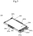
- FIG. 3 is a view illustrating a box body to be attached to the film-covered battery of the present invention.
- FIG. 3 Although a configuration in which the positive and negative electrode lead-out tabs of the film-covered battery are drawn from the end portion on the same side is illustrated in FIG. 3 , the configuration in FIG. 3 may be appropriately modified according to drawing direction or dimension of the tab.
- the space part is formed inside the outer peripheral portion of the frame body 201 illustrated in FIG. 2 , whereas in the frame body 201 illustrated in FIG. 3 , an intermediate plate 204 is set inside the outer peripheral portion, and concave portions in which both surfaces of the intermediate plate serve as bottom portions thereof are formed in both surfaces of the box body.
- Other configurations is the same as those of the frame body of FIG. 2 , so detailed description thereof will be omitted.
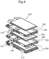
- FIG. 4 is a view illustrating a state where the film-covered batteries of FIG. 1 each attached with the frame body are stacked.
- FIG. 5 is a view illustrating an example of a relationship between a thickness of the film-covered battery and a thickness of the frame body.
- the film-covered battery 100 (not illustrated) is disposed at the lowest stage, and the frame body 201 is placed on the flange portion including the upper end portion, the lower end portion, and the side portions 113 formed in the periphery of the battery element housing 110 using the protruding portions formed in the outer peripheral portion of the frame body.
- the frame body and the film-covered battery are repeatedly piled up in a state where a main surface of the film-covered battery is set in parallel to a horizontal surface.
- the frame body is disposed between the flange portions of the adjacently disposed film-covered batteries.
- an adhesive member 230 is provided in the battery element housing of the lowest-stage film-covered battery, whereby the film-covered battery placed on the lowest-stage film-covered battery is fixed thereto by the adhesive member.
- a thickness of the frame body 201 including the protruding portion is equal to or less than a distance obtained by subtracting a thickness t2 of the flange portion opposite to the protruding portion from a thickness t1 of the film-covered battery.
- the thickness of the frame body 201 including the protruding portion is equal to or less than a distance obtained by subtracting the thickness t2 of the flange portion opposite to the protruding portion from a sum of the thickness t1 of the film-covered battery and a thickness d of the adhesive member.
- the protruding portion in the flange portion where the electrode lead-out tabs exist and where the maximum load is applied to the battery element housed inside the film-covered battery it is possible to minimize the amplitude of a part of the flange portion where the electrode lead-out tab which is most vulnerable to damage is positioned to thereby most effectively obtain resistance to the vibration.
- the outer peripheral portion of the frame body corresponding to the position where the positive and negative electrode lead-out tabs are provided is made wider in width, so as not to allow leading ends of the positive and negative electrode lead-out tabs to protrude from the outer edge of the frame body. As a result, it is possible to obtain a structure further resistant to externally applied vibration.
- the frame body is not a main part that supports the film-covered battery.
- the frame body is not a main part that supports the film-covered battery.
- the protruding portion may be partially provided in the frame body, it is applicable to the film-covered batteries of various thicknesses.
- the protruding portion formed separately from the frame body may be fitted to the frame body, or the protruding portion may be die-molded using a core piece. As a result, it is possible to provide a frame body, a battery, a battery module, and a battery pack excellent in productivity.
- a double faced adhesive tape or an adhesive such as a hot-melt adhesive may be used as the adhesive member for fixing the film-covered battery.
- the double faced adhesive tape is preferably used.
- the film-covered batteries are stacked with the directions of the side from which the positive and negative electrode lead-out tabs are drawn aligned; however, the direction of the side from which the positive and negative electrode lead-out tabs are drawn may be made different.
- the frame body is preferably formed such that an outer peripheral edge thereof coincides with or lies outside outer peripheral edges of the upper end portion outer edge 111a, the lower end portion outer edge 112a, and the side portion outer edge 113a.
- the configuration described above may be repeated.
- the film-covered batteries are alternately inverted such that the positive and negative electrode tabs overlap each other when the adjacent film-covered batteries are laminated to each other.
- FIG. 4 an example of the battery module in which the frame body of FIG. 2 is placed on the film-covered battery is illustrated; alternatively, however, as illustrated in FIG. 6 , the box body and the frame body may be combined to form the battery module.
- a box body 201d is disposed at the lowest stage, and the film-covered battery is placed on the intermediate plate 204 of the box body.
- a frame part of a frame body 201c is placed on the flange portion formed around the battery element housing 110 of the film-covered battery 100 disposed at the lowest box body.
- a distance between the intermediate plate 204 of the box body and a plane corresponding to a surface 203 of an outer peripheral portion of the box body is equal to or less than a distance between a lower surface of the flange portion of the lowest-stage film-covered battery and an upper surface of the intermediate plate of the box body.
- a thickness of the frame body 201c is made equal to or less than a gap between the upper surface of the flange portion of the lowest-stage film-covered battery and the lower surface of the flange portion of the film-covered battery laminated on the lowest-stage film-covered battery.
Landscapes
- Chemical & Material Sciences (AREA)
- Chemical Kinetics & Catalysis (AREA)
- Electrochemistry (AREA)
- General Chemical & Material Sciences (AREA)
- Battery Mounting, Suspending (AREA)
- Connection Of Batteries Or Terminals (AREA)
- Sealing Battery Cases Or Jackets (AREA)
- Electric Double-Layer Capacitors Or The Like (AREA)
Abstract
Description
- The present invention relates to a battery module and a battery pack which incorporate a secondary battery and an electric vehicle mounted with the battery pack.
- As a power source for a vehicle such as an electric car, an electric motorcycle, or a power-assisted bicycle or as a power source for use in a house or a building, a battery module or a battery pack incorporating a secondary battery is available, and various types of secondary batteries can be used in the battery module or battery pack. Among the various types, a lithium ion battery excellent in both mass and volume energy densities and providing high voltage per unit battery is preferably used.
- The lithium ion battery includes a wound type obtained by winding, in a roll shape, a stack of strip shaped positive and negative electrodes through a separator and a stacked type obtained by stacking flat plate-positive and negative electrodes through a separator. The lithium ion battery generally has a columnar or a flat shape as a whole.
- Among them, a flat-shaped lithium ion battery obtained by packaging a battery element with a film-like member has a substantially rectangular shape to be tightly housed in a device, and has a light weight. Thus, with such a flat-shaped lithium ion battery, it is possible to realize a device having high volume energy density or a high mass energy density. In particular, the light weight property is significant for a power source battery for a power motor for, e.g., a vehicle.
- A film-covered battery disclosed in Patent Document 1 is lower in strength against impact than a battery housed in a casing such as an aluminum can having a large thickness. Therefore, a frame member in which an opening is formed at a position corresponding to a power generation element of the film-covered battery is disposed so as to retain a heat-welded portion at a periphery of a covering material. Further, as another structure for supporting a battery with a frame, Patent Document 2 proposes a structure in which an elastic pressurizing member is provided at a part of the frame so as to surely bring a heat radiating plate provided in the battery into tight contact with the battery.
-
- Patent Document 1:
JP2004-103258A - Patent Document 2:
JP2012-523086A WO2010/114317 - The film-covered battery has a flexible film as a covering body and is thus different in terms of structure from a battery having, as the covering body, a can-like vessel produced in a predetermined size. More specifically, a difference in thickness of a battery element housed in the film-covered battery means a difference in an outer dimension of the film-covered battery. Accordingly, the dimension differs depending on a variation in manufacturing, not to mention depending on a size of the battery element. In the battery described in Patent Document 1 or Patent Document 2, in order to cope with a difference in thickness of the film-covered battery caused due to a difference in electric capacity of a unit battery or a manufacturing variation, it is necessary to prepare a frame of a size matching with the film-covered battery having a large thickness.
- Further, when a plurality of the film-covered batteries are stacked to produce a battery module in which the film-covered batteries are housed in a battery casing, the following problem arises. That is, when a thickness of the frame is excessively large relative to the thickness of the film-covered battery, volume efficiency of the battery module is reduced as the number of the film-covered batteries to be stacked is increased. In order to cope with such a problem, it is necessary to prepare frame bodies having different sizes according to the thickness of the film-covered battery.
- In a case of the battery described in Patent Document 1, an outer peripheral portion of the film-covered battery is supported by the whole periphery of frame body. Thus, in order to prevent the outer peripheral portion from being damaged, it is necessary to prepare a frame body having a uniform thickness, resulting in a necessity of forming frame bodies of various dimensions corresponding to the thickness, which wanes productivity.
- Further, when the frame body described in Patent Document 1 or Patent Document 2 is used as a main retaining member for the film-covered battery, the frame body retains the peripheral portion of the film-covered battery. The peripheral portion of the film-covered battery is a portion where the films are heat fused to each other or a portion where the films are only folded over on each other, that is, a small thickness portion. Thus, the peripheral portion is easily reduced in mechanical strength and, when mechanical stress with respect to the peripheral portion is increased, the covering film may be broken, or the heat fused portion may be opened.
- An object of the present invention is to provide a film-covered battery, a battery module in which a plurality of the film-covered batteries are stacked, and a battery pack in which a protective circuit is connected to the film-covered batteries and battery module, which have high durability against external impact, and a manufacturing method therefor.
- According to the present invention, there is provided a battery module having a plurality of stacked film-covered batteries, the film-covered batteries each including: a battery element housing that houses therein a battery element; a flange portion formed partially or entirely in a covering film around the battery element housing; and positive and negative electrode lead-out tabs. The battery module further comprising a frame body having an outer peripheral portion and an opening portion inside the outer peripheral portion. The outer peripheral portion of the frame body is disposed between the flange portions of adjacent film-covered batteries. A protruding portion is formed on a surface of the outer peripheral portion that is opposed to the flange portion so as to protrude toward the flange side. A thickness of a part of the frame body that includes the protruding portion is equal to or less than a distance obtained by subtracting a thickness of the flange portion opposite to the protruding portion from a thickness of the film-covered battery.
- According to the present invention, it is possible to significantly reduce mechanical stress to the flange portion positioned at the outer peripheral portion of the film-covered battery. Further, since the protruding portion may be partially provided in the frame body, the protruding portion may be die-molded using a core piece even when a thickness of a unit battery is changed, thereby making it possible to provide a frame body, a battery, a battery module, and a battery pack excellent in productivity.
- Further, by placing the protruding portion on a part of the flange portion at which the electrode lead-out tabs are drawn, it is possible to protect a part of the flange portion where the electrode lead-out tabs exist and where mechanical stress is most easily applied from impact.
- In particular, even when the battery module is a type that is used in an environment always subjected to vibration and impact, like a battery module incorporated in a battery module used in an electric car, an electric motorcycle, or a power-assisted bicycle or a battery module incorporated in a battery pack, it is possible to provide a battery module capable of stably operating over a long time and having a high degree of freedom of layout when being incorporated in the power-assisted bicycle or the like.
-
-
FIG. 1 is a view illustrating an example of a film-covered battery used in a battery module according to the present invention; -
FIG. 2 is a view illustrating an example of a frame body to be attached to the film-covered battery used in the battery module according to the present invention; -
FIG. 3 is a view illustrating a frame body to be attached to the film-covered battery used in the battery module according to the present invention; -
FIG. 4 is a view illustrating an example of an arrangement of the film-covered battery used in the battery module according to the present invention and frame body; -
FIG. 5 is a view illustrating an example of a relationship between a thickness of the film-covered battery used in the battery module according to the present invention and a thickness of the frame body; and -
FIG. 6 is a view illustrating another example of the arrangement of the film-covered battery of the present invention and frame body. -
FIG. 1 is a view illustrating an example of a film-covered battery used in the present invention. A film-coveredbattery 100 is covered with a film covering material in which films having high weather resistance are stacked on an outer surface side thereof and heat-weldable films are laminated on an inner surface side thereof. For example, films having high weather resistance, such as polyamide films or polyethylene terephthalate films are stacked on an outer surface side of an aluminum foil, and heat-weldable synthetic resin films such as polyethylene films are laminated on an inner surface side thereof. - The film-covered battery houses a battery element, electrolyte, and the like in a battery element housing 110 of the film covering material, and a positive electrode lead-out
tab 120 and a negative electrode lead-outtab 130 are drawn outside the film covering material. - As the battery element, a battery element obtained by laminating a positive electrode supporting a positive electrode active material and a negative electrode supporting a negative electrode active material through a separator, a battery element obtained by winding a stack of a strip shaped positive and negative electrodes through a separator in a roll shape, or a battery element obtained by pressurizing the wound stack of the positive and negative electrodes in a flat shape is used.
- One end of the positive electrode lead-out tab is electrically connected to the positive electrode, and the other end thereof is drawn outside the film covering material. One end of the negative electrode lead-out tab is electrically connected to the negative electrode, and the other end thereof is drawn outside the film covering material.
- One end of a positive
electrode extension tab 122 can be jointed to the positive electrode lead-outtab 120 of the film-coveredbattery 100 by a welding means such as a spot welding or an ultrasonic welding. InFIG. 1 , the one end of the positiveelectrode extension tab 122 is jointed to a leading end of the positive electrode tab, and the other end of the positive electrode extension tab is disposed so as to be directed in a perpendicular direction to the drawing direction of the positive electrode lead-out tab, that is, directed to a side where the negative lead-out tab does not exist. - Further, a negative
electrode extension tab 132 whose one end is jointed to the negative electrode lead-outtab 130 is drawn in a direction opposite to the drawing direction of the positiveelectrode extension tab 122. - The positive and negative electrode extension tabs may be formed of nickel or a nickel alloy.
- The film covering material includes an
upper end portion 111, an upper end portionouter edge 111a, alower end portion 112, a lower end portionouter edge 112a, aside portion 113, a side portionouter edge 113a. - In
FIG. 1 , a direction of theupper end portion 111 corresponds to the drawing direction of the positive and negative lead-out tabs. A flange portion including theupper end portion 111, alower end portion 112, andside portion 113 is partially or entirely sealed by heat-welding after injection of electrolyte into the battery element housing, allowing the electrolyte to be held inside the film covering material. - The film covering material may be used as follows. For example, four sides at outer edges of two film covering materials disposed on both surfaces of the battery element are heat-welded. Alternatively, a single film covering material is folded at a center thereof to cover the both surfaces of the battery element, and then the remaining three sides are heat-welded after injection of the electrolyte. That is, the sealed portion may be appropriately changed.
- The positive electrode lead-out
tab 120 and the negative electrode lead-outtab 130 may both be drawn from the upper end portion outer edge or lower end portion outer edge or may be separately drawn from the opposing outer edges. - For descriptive convenience, one end portion from which at least one of the positive and negative electrode lead-out
tabs - In an example of a configuration of the film-covered battery of the present invention, a lithium-transition metal composite oxide such as a lithium-manganese composite oxide or a lithium cobalt composite oxide may be used as the active material for the positive electrode of the battery body. Further, a conductivity imparting material or other additives may be added to the above active material as needed. As a current collecting foil, metal such as an aluminum foil that is stable even when a positive potential is applied thereto can be taken as an example.
- Further, as the negative electrode, it is possible to use a negative electrode obtained by applying a slurry obtained by mixing a carbon material capable of doping and dedoping lithium, a conductivity imparting material such as carbon black, binder, and the like to a copper foil, followed by drying.
- Examples of a storage element that uses the film covering material and has the positive and negative lead-out tabs which are drawn outside the film covering material include an electric double-layer capacitor and a lithium ion capacitor. A configuration of a portion where the battery stacked body of the present invention is housed in the covering film may be applied to the above storage elements.
-
FIG. 2 is a view illustrating an example of a frame body to be attached to the film-covered battery of the present invention. Aframe body 201 is produced using molding of a synthetic resin, such as ABS or polycarbonate, having high strength. Theframe body 201 has, inside aframe part 203 corresponding to the flange portion of the outer peripheral portion of the film-covered battery (not illustrated), aspace part 202 corresponding to the battery element housing. - A protruding
portions frame part 203 of theframe body 201 toward the flange side so as to be opposed to the flange portion of the film-covered battery. - The protruding
portion 203a is provided at a position on the surface of the frame body opposite to a position on the flange portion of the film-covered battery described inFIG. 1 at which one electrode lead-out tab is disposed, and the protrudingportion 203f is provided at a position on the surface of the frame body opposite to a position at which the other electrode lead-out tab is disposed. - Further, the protruding portions are provided at positions other than those at which the electrode lead-out tab are disposed so as to allow the frame body to be stably placed on the flange portion by the protruding portions of the frame body.
- The protruding
portions portions portions portions - In
FIG. 2 , the protruding portion of the frame body is provided on both surface of the outer peripheral portion of the frame body; however, depending on a shape of the film-covered battery, the protruding portion may be provided only on one side surface. - Providing the frame body can prevent the film-covered battery or a battery module incorporating the film-covered battery in a battery casing from colliding with an inner wall or the like of a battery casing (not illustrated) housing the film-covered battery or battery module even when impact is applied to the battery module or the battery pack.
- Further, providing the protruding portions on the frame body prevents violent collision between the flange portion of the film-covered battery and the frame body. A part of the flange portion of the film-covered battery, from which the positive electrode lead-out tab or the negative electrode lead-out tab is drawn, is most vulnerable to impact from the lead-out tab, so that the protruding portion is preferably disposed at a portion opposite to the flange portion where the lead-out tab is provided.
- This reduces amplitude of the flange portion where the lead-out tab is provided upon application of the impact, thereby significantly reducing damage of the covering film.
- In the present invention, it is preferable to provide the protruding portion at positions on the frame body corresponding at least to the
upper end portion 111 andlower end portion 112 or at positions on the frame body corresponding to at least the upper end portion and the both side portions. - A
flat surface 209 is formed at a side surface of the outer peripheral portion of the frame body that is opposed to a side surface thereof on the space part side. As a result, when a plurality of film-covered batteries are stacked, and a plurality of frame bodies are disposed accordingly, a fixing member such as an adhesive tape or a reinforcing member can be easily bonded or fixed to theflat surface 209. - Further, for reducing a weight of the battery module, a
concave portion 206 may be formed. Theconcave portion 206 may be formed as a through hole; however, an inner surface side of the outer peripheral portion of the frame body contacts the film covering body, so that the inner surface side is preferably flat. Similarly, the concave portion may be formed in surfaces at the upper and lower end portions that are opposed to the side at which the space part is disposed. - A side
surface fastening portion 210a is provided at the side surface of the frame body. Further, another side surface fastening portion is provided on an opposite side to the side surface of the frame body at which the sidesurface fastening portion 210a is positioned. - As shown by Figures such as
FIG. 1 , the frame body is placed on the film-covered battery provided with the positive electrode extension tab and negative electrode extension tab. Then, one of the positive and negative extension tabs of the film-covered battery is disposed so as to overlap the sidesurface fastening portion 210a, and the tab is fixed to the frame body using a fastening means such as screwing, pinning, or welding, whereby the frame body can be disposed between the film-covered batteries connected in series. The sidesurface fastening portion 210b on the opposite side and the other one of the positive and negative extension tabs can be connected in the same manner. -
FIG. 3 is a view illustrating a box body to be attached to the film-covered battery of the present invention. - Although a configuration in which the positive and negative electrode lead-out tabs of the film-covered battery are drawn from the end portion on the same side is illustrated in
FIG. 3 , the configuration inFIG. 3 may be appropriately modified according to drawing direction or dimension of the tab. - The space part is formed inside the outer peripheral portion of the
frame body 201 illustrated inFIG. 2 , whereas in theframe body 201 illustrated inFIG. 3 , anintermediate plate 204 is set inside the outer peripheral portion, and concave portions in which both surfaces of the intermediate plate serve as bottom portions thereof are formed in both surfaces of the box body. Other configurations is the same as those of the frame body ofFIG. 2 , so detailed description thereof will be omitted. -
FIG. 4 is a view illustrating a state where the film-covered batteries ofFIG. 1 each attached with the frame body are stacked. -
FIG. 5 is a view illustrating an example of a relationship between a thickness of the film-covered battery and a thickness of the frame body. - The film-covered battery 100 (not illustrated) is disposed at the lowest stage, and the
frame body 201 is placed on the flange portion including the upper end portion, the lower end portion, and theside portions 113 formed in the periphery of thebattery element housing 110 using the protruding portions formed in the outer peripheral portion of the frame body. In this example, for descriptive convenience, the frame body and the film-covered battery are repeatedly piled up in a state where a main surface of the film-covered battery is set in parallel to a horizontal surface. When the main surface of the film-covered battery is set vertical to a floor surface, the frame body is disposed between the flange portions of the adjacently disposed film-covered batteries. - In
FIG. 4 , anadhesive member 230 is provided in the battery element housing of the lowest-stage film-covered battery, whereby the film-covered battery placed on the lowest-stage film-covered battery is fixed thereto by the adhesive member. In this state, a thickness of theframe body 201 including the protruding portion is equal to or less than a distance obtained by subtracting a thickness t2 of the flange portion opposite to the protruding portion from a thickness t1 of the film-covered battery. - Further, when the adjacent film-covered batteries are connected through the adhesive member, the thickness of the
frame body 201 including the protruding portion is equal to or less than a distance obtained by subtracting the thickness t2 of the flange portion opposite to the protruding portion from a sum of the thickness t1 of the film-covered battery and a thickness d of the adhesive member. - As a result, a load corresponding to only one frame body is applied to the flange of the film-covered battery. Thus, it is possible to significantly reduce a load to be applied to the flange as compared with a conventional configuration in which the film-covered battery is supported mainly by the frame body.
- Further, by providing the protruding portion in the flange portion where the electrode lead-out tabs exist and where the maximum load is applied to the battery element housed inside the film-covered battery, it is possible to minimize the amplitude of a part of the flange portion where the electrode lead-out tab which is most vulnerable to damage is positioned to thereby most effectively obtain resistance to the vibration.
- Further, the outer peripheral portion of the frame body corresponding to the position where the positive and negative electrode lead-out tabs are provided is made wider in width, so as not to allow leading ends of the positive and negative electrode lead-out tabs to protrude from the outer edge of the frame body. As a result, it is possible to obtain a structure further resistant to externally applied vibration.
- Further, when the adjacent film-covered batteries are connected through the adhesive member, the frame body is not a main part that supports the film-covered battery. Thus, even when a part contacting the flange of the film-covered battery is the protruding portion partially provided in the frame body, it is possible to significantly reduce mechanical stress to the flange portion, thereby preventing damage of the flange portion.
- Since the protruding portion may be partially provided in the frame body, it is applicable to the film-covered batteries of various thicknesses. For example, the protruding portion formed separately from the frame body may be fitted to the frame body, or the protruding portion may be die-molded using a core piece. As a result, it is possible to provide a frame body, a battery, a battery module, and a battery pack excellent in productivity.
- As the adhesive member for fixing the film-covered battery, a double faced adhesive tape or an adhesive such as a hot-melt adhesive may be used. In terms of workability, the double faced adhesive tape is preferably used.
- In
FIGS. 2 and3 , the film-covered batteries are stacked with the directions of the side from which the positive and negative electrode lead-out tabs are drawn aligned; however, the direction of the side from which the positive and negative electrode lead-out tabs are drawn may be made different. - Further, the frame body is preferably formed such that an outer peripheral edge thereof coincides with or lies outside outer peripheral edges of the upper end portion
outer edge 111a, the lower end portionouter edge 112a, and the side portionouter edge 113a. - When a large number of the film-covered batteries are stacked, the configuration described above may be repeated. When the batteries are connected in series, the film-covered batteries are alternately inverted such that the positive and negative electrode tabs overlap each other when the adjacent film-covered batteries are laminated to each other.
- In
FIG. 4 , an example of the battery module in which the frame body ofFIG. 2 is placed on the film-covered battery is illustrated; alternatively, however, as illustrated inFIG. 6 , the box body and the frame body may be combined to form the battery module. - In
FIG. 6 , abox body 201d is disposed at the lowest stage, and the film-covered battery is placed on theintermediate plate 204 of the box body. A frame part of aframe body 201c is placed on the flange portion formed around thebattery element housing 110 of the film-coveredbattery 100 disposed at the lowest box body. - Further, another film-covered battery is bonded by the
adhesive member 230 to the battery element housing of the film-covered battery disposed at the lowest box body. In this state, a distance between theintermediate plate 204 of the box body and a plane corresponding to asurface 203 of an outer peripheral portion of the box body is equal to or less than a distance between a lower surface of the flange portion of the lowest-stage film-covered battery and an upper surface of the intermediate plate of the box body. - A thickness of the
frame body 201c is made equal to or less than a gap between the upper surface of the flange portion of the lowest-stage film-covered battery and the lower surface of the flange portion of the film-covered battery laminated on the lowest-stage film-covered battery. With this configuration, it is possible to prevent the film-covered battery from being retained only by the flange portion corresponding to the outer peripheral portion of the box body or the frame body, there by reducing a load to be applied to the flange portion. - There can be provided a battery module and a battery pack highly resistant to vibration and impact.
-
- 100:
- Film-covered battery
- 110:
- Battery element housing
- 111a:
- Upper end portion outer edge
- 112a:
- Lower end portion outer edge
- 113:
- Side portion
- 113a:
- Side portion outer edge
- 120:
- Positive electrode lead-out tab
- 122:
- Positive electrode extension tab
- 130:
- Negative electrode lead-out tab
- 132:
- Negative electrode extension tab
- 201, 201a, 201c, 201d:
- Frame body
- 202:
- Space part
- 203:
- Frame part
- 203a, 203b, 203c, 203d, 203e, 203f:
- Protruding portion
- 230:
- Adhesive member
Claims (8)
- A battery module characterized by comprising a plurality of stacked film-covered batteries, the film-covered batteries each including:a battery element housing that houses therein a battery element;a flange portion formed partially or entirely in a covering film around the battery element housing; andpositive and negative electrode lead-out tabs,the battery module further comprising a frame body having an outer peripheral portion and an opening portion inside the outer peripheral portion, whereinthe outer peripheral portion of the frame body is disposed between the flange portions of adjacent film-covered batteries,a protruding portion is formed on a surface of the outer peripheral portion that is opposed to the flange portion so as to protrude toward the flange side,a thickness of a part of the frame body that includes the protruding portion is equal to or less than a distance obtained by subtracting a thickness of the flange portion opposite to the protruding portion from a thickness of the film-covered battery.
- The battery module according to claim 1, characterized in that
the protruding portion contacts at least the flange portion of a side at which the positive electrode lead-out tab is drawn from the covering film and the flange portion of a side at which the negative electrode lead-out tab is drawn from the covering film. - The battery module according to claim 1 or 2, characterized in that
the film-covered battery is fixed to at least one of its adjacent film-covered batteries through an adhesive member. - The battery module according to any one of claims 1 to 3, characterized by comprising two or more frame bodies, wherein
the two or more frame bodies are fixed to each other, using an adhesive member, at their outside surfaces different from side surfaces defining the opening portions thereof. - The battery module according to any one of claims 1 to 4, characterized in that
at least one of the positive electrode lead-out tab and a positive electrode extension tab electrically connected to the positive electrode lead-out tab and at least one of the negative electrode lead-out tab and a negative electrode extension tab electrically connected to the negative electrode lead-out tab are fixed to the frame body using a fastening member. - The battery module according to any one of claims 1 to 5, characterized by further comprising a box body having an outer peripheral portion, an intermediate plate inside the outer peripheral portion, and a concave portion in which at least one of surfaces of the intermediate plate serves as a bottom portion thereof, wherein
the film-covered battery is fixed to the intermediate plate of the box body by an adhesive member, and the film-covered battery fixed to the intermediate plate is fixed to its adjacent film-covered battery through an adhesive member. - The battery module according to any one of claims 1 to 6, characterized in that
the box body is disposed at the outermost position in a battery module lamination direction. - A battery module characterized by comprising a plurality of stacked film-covered batteries, the film-covered batteries each including:a battery element housing that houses therein a battery element;a flange portion formed partially or entirely in a covering film around the battery element housing; andpositive and negative electrode lead-out tabs,the battery module further comprising a box body having an outer peripheral portion, an intermediate plate inside the outer peripheral portion, and a concave portion in which at least one of surfaces of the intermediate plate serves as a bottom portion thereof, whereinthe film-covered battery is fixed to the intermediate plate of the box body by an adhesive member, and another box body is fixed to the film-covered battery fixed to the intermediate plate through an adhesive member.
Applications Claiming Priority (2)
| Application Number | Priority Date | Filing Date | Title |
|---|---|---|---|
| JP2013119997 | 2013-06-06 | ||
| PCT/JP2014/062921 WO2014196331A1 (en) | 2013-06-06 | 2014-05-15 | Battery module |
Publications (2)
| Publication Number | Publication Date |
|---|---|
| EP3007248A1 true EP3007248A1 (en) | 2016-04-13 |
| EP3007248A4 EP3007248A4 (en) | 2017-03-29 |
Family
ID=52007984
Family Applications (1)
| Application Number | Title | Priority Date | Filing Date |
|---|---|---|---|
| EP14807018.8A Withdrawn EP3007248A4 (en) | 2013-06-06 | 2014-05-15 | Battery module |
Country Status (6)
| Country | Link |
|---|---|
| US (1) | US10236487B2 (en) |
| EP (1) | EP3007248A4 (en) |
| JP (1) | JP6478284B2 (en) |
| CN (1) | CN105378970B (en) |
| WO (1) | WO2014196331A1 (en) |
| ZA (1) | ZA201508669B (en) |
Cited By (1)
| Publication number | Priority date | Publication date | Assignee | Title |
|---|---|---|---|---|
| EP4738565A1 (en) * | 2024-10-31 | 2026-05-06 | Samsung Sdi Co., Ltd. | Battery module |
Families Citing this family (12)
| Publication number | Priority date | Publication date | Assignee | Title |
|---|---|---|---|---|
| DE102015225188B4 (en) * | 2015-12-15 | 2020-10-08 | Bayerische Motoren Werke Aktiengesellschaft | Energy storage module |
| WO2018066094A1 (en) * | 2016-10-05 | 2018-04-12 | 住友電気工業株式会社 | Frame body, cell frame, cell stack, and redox flow battery |
| ES3056222T3 (en) * | 2020-08-14 | 2026-02-19 | Lg Energy Solution Ltd | Electrode assembly comprising anode and anode sheet having improved electrode stacking properties and manufacturing method therefor |
| JP1697204S (en) * | 2021-04-30 | 2021-10-18 | ||
| JP1697202S (en) * | 2021-04-30 | 2021-10-18 | ||
| JP1697203S (en) * | 2021-04-30 | 2021-10-18 | ||
| JP1697238S (en) * | 2021-04-30 | 2021-10-18 | ||
| USD1021767S1 (en) * | 2021-06-03 | 2024-04-09 | Lg Energy Solution, Ltd. | Battery |
| JP1746677S (en) * | 2021-06-03 | 2023-06-19 | battery | |
| JP1736633S (en) * | 2021-06-03 | 2023-02-13 | battery | |
| USD1023910S1 (en) * | 2021-11-23 | 2024-04-23 | Bard Peripheral Vascular, Inc.. | Battery pack |
| USD1023912S1 (en) * | 2021-11-23 | 2024-04-23 | Bard Peripheral Vascular, Inc. | Battery pack |
Family Cites Families (13)
| Publication number | Priority date | Publication date | Assignee | Title |
|---|---|---|---|---|
| JPH1116546A (en) | 1997-06-24 | 1999-01-22 | Yuasa Corp | Flat battery |
| JPH11111250A (en) * | 1997-10-06 | 1999-04-23 | Japan Storage Battery Co Ltd | Battery |
| JP4000961B2 (en) | 2002-09-04 | 2007-10-31 | 日産自動車株式会社 | Assembled battery |
| KR100964216B1 (en) | 2003-06-24 | 2010-06-17 | 삼성에스디아이 주식회사 | Pouch Battery Pack |
| KR100872616B1 (en) * | 2004-03-31 | 2008-12-09 | 닛본 덴끼 가부시끼가이샤 | Electrical device with film covering, frame member, and housing system for electrical device with film covering |
| JP4461940B2 (en) | 2004-07-20 | 2010-05-12 | 日産自動車株式会社 | Assembled battery |
| JP4539742B2 (en) | 2008-03-18 | 2010-09-08 | Tdk株式会社 | Electrochemical devices |
| US8202645B2 (en) * | 2008-10-06 | 2012-06-19 | Lg Chem, Ltd. | Battery cell assembly and method for assembling the battery cell assembly |
| WO2010114317A2 (en) | 2009-04-01 | 2010-10-07 | 주식회사 엘지화학 | Battery module having excellent radiation property and medium to large sized battery pack |
| JP2010244949A (en) | 2009-04-09 | 2010-10-28 | Nec Energy Devices Ltd | Battery module |
| US20140017541A1 (en) | 2011-03-31 | 2014-01-16 | Nec Energy Devices, Ltd. | Battery pack and electric bicycle |
| US20130164578A1 (en) * | 2011-12-21 | 2013-06-27 | Edward Thomas Sweet | Battery module |
| JP5968211B2 (en) | 2012-02-14 | 2016-08-10 | 住友重機械工業株式会社 | Power storage module, manufacturing method thereof, and work machine |
-
2014
- 2014-05-15 CN CN201480031055.7A patent/CN105378970B/en active Active
- 2014-05-15 EP EP14807018.8A patent/EP3007248A4/en not_active Withdrawn
- 2014-05-15 WO PCT/JP2014/062921 patent/WO2014196331A1/en not_active Ceased
- 2014-05-15 US US14/894,553 patent/US10236487B2/en active Active
- 2014-05-15 JP JP2015521365A patent/JP6478284B2/en active Active
-
2015
- 2015-11-25 ZA ZA2015/08669A patent/ZA201508669B/en unknown
Cited By (1)
| Publication number | Priority date | Publication date | Assignee | Title |
|---|---|---|---|---|
| EP4738565A1 (en) * | 2024-10-31 | 2026-05-06 | Samsung Sdi Co., Ltd. | Battery module |
Also Published As
| Publication number | Publication date |
|---|---|
| ZA201508669B (en) | 2017-08-30 |
| CN105378970A (en) | 2016-03-02 |
| JPWO2014196331A1 (en) | 2017-02-23 |
| JP6478284B2 (en) | 2019-03-06 |
| US10236487B2 (en) | 2019-03-19 |
| US20160126516A1 (en) | 2016-05-05 |
| WO2014196331A1 (en) | 2014-12-11 |
| CN105378970B (en) | 2018-09-07 |
| EP3007248A4 (en) | 2017-03-29 |
Similar Documents
| Publication | Publication Date | Title |
|---|---|---|
| US10236487B2 (en) | Battery module | |
| US12308453B2 (en) | Battery module | |
| US11594776B2 (en) | Battery module including heat shrinkable tube | |
| JP6563589B2 (en) | Secondary battery pouch exterior | |
| EP2549561B1 (en) | Pouch type case and battery pack including same | |
| CN104584264B (en) | Battery | |
| US10811721B2 (en) | Accumulator device | |
| EP2849247B1 (en) | Rechargeable battery | |
| JP6716102B1 (en) | Electric storage device, electric storage device assembly, and electric vehicle | |
| KR101596269B1 (en) | Battery Cell of Novel Structure | |
| JP6278466B2 (en) | Battery pack | |
| CN113745744A (en) | Solid battery module and solid battery monomer | |
| JP2007087907A (en) | Case structure of battery cell | |
| KR20170086346A (en) | Battery cell | |
| US9099692B2 (en) | Rechargeable battery | |
| KR20220094758A (en) | Battery module | |
| KR20190069875A (en) | Battery module having a crush plate and Method for manufacturing the same | |
| JP5205775B2 (en) | battery | |
| KR102267587B1 (en) | Battery Pack | |
| KR20160054268A (en) | Secondary battery cell and battery module including the same | |
| JPWO2014141525A1 (en) | Assembled battery | |
| KR20190005405A (en) | Battery Module | |
| KR20250117901A (en) | Battery device | |
| KR20250122816A (en) | Battery cell and battery device having the same | |
| JP2014179295A (en) | Battery module |
Legal Events
| Date | Code | Title | Description |
|---|---|---|---|
| PUAI | Public reference made under article 153(3) epc to a published international application that has entered the european phase |
Free format text: ORIGINAL CODE: 0009012 |
|
| 17P | Request for examination filed |
Effective date: 20151126 |
|
| AK | Designated contracting states |
Kind code of ref document: A1 Designated state(s): AL AT BE BG CH CY CZ DE DK EE ES FI FR GB GR HR HU IE IS IT LI LT LU LV MC MK MT NL NO PL PT RO RS SE SI SK SM TR |
|
| AX | Request for extension of the european patent |
Extension state: BA ME |
|
| DAX | Request for extension of the european patent (deleted) | ||
| RIC1 | Information provided on ipc code assigned before grant |
Ipc: H01M 2/10 20060101AFI20161102BHEP |
|
| A4 | Supplementary search report drawn up and despatched |
Effective date: 20170223 |
|
| RIC1 | Information provided on ipc code assigned before grant |
Ipc: H01M 2/10 20060101AFI20170218BHEP |
|
| 17Q | First examination report despatched |
Effective date: 20180612 |
|
| RAP1 | Party data changed (applicant data changed or rights of an application transferred) |
Owner name: ENVISION AESC ENERGY DEVICES LTD. |
|
| STAA | Information on the status of an ep patent application or granted ep patent |
Free format text: STATUS: THE APPLICATION IS DEEMED TO BE WITHDRAWN |
|
| 18D | Application deemed to be withdrawn |
Effective date: 20201107 |