EP3007041A1 - Display panel with pressing sensor, and electronic device with pressing input function - Google Patents
Display panel with pressing sensor, and electronic device with pressing input function Download PDFInfo
- Publication number
- EP3007041A1 EP3007041A1 EP14804556.0A EP14804556A EP3007041A1 EP 3007041 A1 EP3007041 A1 EP 3007041A1 EP 14804556 A EP14804556 A EP 14804556A EP 3007041 A1 EP3007041 A1 EP 3007041A1
- Authority
- EP
- European Patent Office
- Prior art keywords
- pressure sensor
- display panel
- polarizing plate
- piezoelectric film
- pressing
- Prior art date
- Legal status (The legal status is an assumption and is not a legal conclusion. Google has not performed a legal analysis and makes no representation as to the accuracy of the status listed.)
- Granted
Links
Images




Classifications
-
- G—PHYSICS
- G02—OPTICS
- G02B—OPTICAL ELEMENTS, SYSTEMS OR APPARATUS
- G02B5/00—Optical elements other than lenses
- G02B5/30—Polarising elements
- G02B5/3025—Polarisers, i.e. arrangements capable of producing a definite output polarisation state from an unpolarised input state
-
- G—PHYSICS
- G02—OPTICS
- G02F—OPTICAL DEVICES OR ARRANGEMENTS FOR THE CONTROL OF LIGHT BY MODIFICATION OF THE OPTICAL PROPERTIES OF THE MEDIA OF THE ELEMENTS INVOLVED THEREIN; NON-LINEAR OPTICS; FREQUENCY-CHANGING OF LIGHT; OPTICAL LOGIC ELEMENTS; OPTICAL ANALOGUE/DIGITAL CONVERTERS
- G02F1/00—Devices or arrangements for the control of the intensity, colour, phase, polarisation or direction of light arriving from an independent light source, e.g. switching, gating or modulating; Non-linear optics
- G02F1/01—Devices or arrangements for the control of the intensity, colour, phase, polarisation or direction of light arriving from an independent light source, e.g. switching, gating or modulating; Non-linear optics for the control of the intensity, phase, polarisation or colour
- G02F1/13—Devices or arrangements for the control of the intensity, colour, phase, polarisation or direction of light arriving from an independent light source, e.g. switching, gating or modulating; Non-linear optics for the control of the intensity, phase, polarisation or colour based on liquid crystals, e.g. single liquid crystal display cells
- G02F1/133—Constructional arrangements; Operation of liquid crystal cells; Circuit arrangements
- G02F1/1333—Constructional arrangements; Manufacturing methods
- G02F1/1335—Structural association of cells with optical devices, e.g. polarisers or reflectors
- G02F1/133528—Polarisers
-
- G—PHYSICS
- G06—COMPUTING OR CALCULATING; COUNTING
- G06F—ELECTRIC DIGITAL DATA PROCESSING
- G06F3/00—Input arrangements for transferring data to be processed into a form capable of being handled by the computer; Output arrangements for transferring data from processing unit to output unit, e.g. interface arrangements
- G06F3/01—Input arrangements or combined input and output arrangements for interaction between user and computer
- G06F3/03—Arrangements for converting the position or the displacement of a member into a coded form
- G06F3/041—Digitisers, e.g. for touch screens or touch pads, characterised by the transducing means
- G06F3/0412—Digitisers structurally integrated in a display
-
- G—PHYSICS
- G06—COMPUTING OR CALCULATING; COUNTING
- G06F—ELECTRIC DIGITAL DATA PROCESSING
- G06F3/00—Input arrangements for transferring data to be processed into a form capable of being handled by the computer; Output arrangements for transferring data from processing unit to output unit, e.g. interface arrangements
- G06F3/01—Input arrangements or combined input and output arrangements for interaction between user and computer
- G06F3/03—Arrangements for converting the position or the displacement of a member into a coded form
- G06F3/041—Digitisers, e.g. for touch screens or touch pads, characterised by the transducing means
- G06F3/044—Digitisers, e.g. for touch screens or touch pads, characterised by the transducing means by capacitive means
- G06F3/0445—Digitisers, e.g. for touch screens or touch pads, characterised by the transducing means by capacitive means using two or more layers of sensing electrodes, e.g. using two layers of electrodes separated by a dielectric layer
-
- G—PHYSICS
- G09—EDUCATION; CRYPTOGRAPHY; DISPLAY; ADVERTISING; SEALS
- G09F—DISPLAYING; ADVERTISING; SIGNS; LABELS OR NAME-PLATES; SEALS
- G09F9/00—Indicating arrangements for variable information in which the information is built-up on a support by selection or combination of individual elements
-
- G—PHYSICS
- G02—OPTICS
- G02F—OPTICAL DEVICES OR ARRANGEMENTS FOR THE CONTROL OF LIGHT BY MODIFICATION OF THE OPTICAL PROPERTIES OF THE MEDIA OF THE ELEMENTS INVOLVED THEREIN; NON-LINEAR OPTICS; FREQUENCY-CHANGING OF LIGHT; OPTICAL LOGIC ELEMENTS; OPTICAL ANALOGUE/DIGITAL CONVERTERS
- G02F1/00—Devices or arrangements for the control of the intensity, colour, phase, polarisation or direction of light arriving from an independent light source, e.g. switching, gating or modulating; Non-linear optics
- G02F1/01—Devices or arrangements for the control of the intensity, colour, phase, polarisation or direction of light arriving from an independent light source, e.g. switching, gating or modulating; Non-linear optics for the control of the intensity, phase, polarisation or colour
- G02F1/13—Devices or arrangements for the control of the intensity, colour, phase, polarisation or direction of light arriving from an independent light source, e.g. switching, gating or modulating; Non-linear optics for the control of the intensity, phase, polarisation or colour based on liquid crystals, e.g. single liquid crystal display cells
- G02F1/133—Constructional arrangements; Operation of liquid crystal cells; Circuit arrangements
- G02F1/1333—Constructional arrangements; Manufacturing methods
- G02F1/1335—Structural association of cells with optical devices, e.g. polarisers or reflectors
- G02F1/133528—Polarisers
- G02F1/133531—Polarisers characterised by the arrangement of polariser or analyser axes
-
- G—PHYSICS
- G06—COMPUTING OR CALCULATING; COUNTING
- G06F—ELECTRIC DIGITAL DATA PROCESSING
- G06F2203/00—Indexing scheme relating to G06F3/00 - G06F3/048
- G06F2203/041—Indexing scheme relating to G06F3/041 - G06F3/045
- G06F2203/04103—Manufacturing, i.e. details related to manufacturing processes specially suited for touch sensitive devices
-
- G—PHYSICS
- G06—COMPUTING OR CALCULATING; COUNTING
- G06F—ELECTRIC DIGITAL DATA PROCESSING
- G06F2203/00—Indexing scheme relating to G06F3/00 - G06F3/048
- G06F2203/041—Indexing scheme relating to G06F3/041 - G06F3/045
- G06F2203/04105—Pressure sensors for measuring the pressure or force exerted on the touch surface without providing the touch position
Definitions
- the present invention relates to a display panel with pressure sensor capable of detecting pressing a display screen with a finger of the like, and an electronic device with pressing input function provided with the display panel with pressure sensor.
- Patent Literature 1 discloses a touch sensor for detecting an operational position, which is disposed on a front face of a display panel. When an operator touches an operation surface, the touch sensor detects a touch position, and the electronic device executes processing according to the detected operational position.
- Such conventional electronic device with touch sensor includes a display panel requiring a polarizing plate such as a liquid crystal panel
- components constituting the electronic device are disposed as follows.
- a front polarizing plate is disposed on the operation surface (outermost face).
- a touch panel is disposed on the opposite side of the front polarizing plate to the operation surface.
- a liquid crystal panel formed of a pair of glasses that sandwiches liquid crystal therebetween is disposed on the opposite side of the touch panel to the front polarizing plate.
- a rear polarizing plate is disposed on the opposite side of the liquid crystal panel to the touch panel. That is, the touch panel is disposed between the front polarizing plate and the rear polarizing plate.
- a transmission liquid crystal display in the case of a transmission liquid crystal display, light from a backlight disposed on the rear face of the rear polarizing plate penetrates the rear polarizing plate, the liquid crystal panel, the touch panel, and the front polarizing plate in this order and then, is emitted to the operation surface.
- a reflective plate is provided in place of the rear polarizing plate, and light incident from the operation surf ace penetrates the frontpolarizingplate, the touch panel, the liquid crystal panel, the reflective plate, the liquid crystal panel, the touch panel, and the front polarizing plate in this order and then, returns to the operation surface.
- the front polarizing plate and the rear polarizing plate have the property of transmitting only a wave (light wave) vibrating in a certain direction.
- the direction in which the wave is transmitted is a polarizing direction. Accordingly, the polarizing direction of the front polarizing plate, the polarizing direction of the rear polarizing plate, and optical characteristics of the liquid crystal panel are combined to set contrast and transmittance of the liquid crystal display and improve appearance of the display screen.
- a pressure sensor is composed of a piezoelectric element formed of a chiral polymer to detect pressing onto the operation surface.
- the piezoelectric element formed of the chiral polymer has birefringence.
- the refractive index of a wave vibrating in a direction parallel to the drawing direction of a uniaxially drawn L-type polylactic acid (PLLA) is 1.47.
- the refractive index of a wave vibrating in a direction vertical to the drawing direction of the uniaxially drawn L-type polylactic acid (PLLA) is 1.45. This is the retardation property.
- an obj ect of the present invention is to provide a display panel with pressure sensor capable of reproducing desired color even in the presence of a pressure sensor using a piezoelectric element formed of a chiral polymer.
- a display panel with pressure sensor includes a display panel having an image forming panel for controlling light emitted to a front face side to form a displayed image and a front polarizing plate disposed on the front face side of the image forming panel, and a pressure sensor having a piezoelectric film formed of a chiral polymer.
- the pressure sensor is disposed relative to the display panel such that a polarizing direction of the piezoelectric film is parallel to or orthogonal to a polarizing direction of the front polarizing plate.
- the display panel with pressure sensor according to the present invention has either of following configurations.
- the pressure sensor is disposed opposite to the image forming panel across the front polarizing plate.
- the pressure sensor is disposed between the front polarizing plate and the image forming panel.
- the pressure sensor since the pressure sensor is disposed near the operation surface, the pressure detection sensitivity can be increased. Further, the front polarizing plate can be used as a protective layer for the pressure sensor.
- the display panel with pressure sensor of the present invention has a following configuration.
- the chiral polymer forming the piezoelectric film is polylactic acid.
- the polylactic acid is at least uniaxially drawn, and the drawing direction is parallel to or orthogonal to a polarizing direction of the front polarizing plate.
- polylactic acid is used for the piezoelectric film.
- a refractive index in the uniaxial drawing direction as the main drawing direction is different from a refractive index in the direction orthogonal to the uniaxial drawing direction. Accordingly, discoloration of display can be prevented by making the uniaxial drawing direction parallel to or orthogonal to the polarizing direction.
- use of the uniaxially drawn polylactic acid can provide a pressure sensor having a high detection sensitivity of the pressing amount (pressing amount of the operation surface) and an excellent temperature characteristic.
- a buffer member is preferably provided between the pressure sensor and the image forming panel. This configuration can suppress the image forming panel from obstructing displacement of the piezoelectric film due to pressing. This can improve the detection sensitivity of the pressure sensor.
- the pressure sensor may have a position-detecting sensor function of detecting a touch position. This configuration enables detection of the pressing amount as well as the touch position.
- An electronic device with pressing input function of the present invention includes the display panel with pressure sensor according to any one of the display panels, and arithmetic unit that detects a pressing amount based on a detection signal of the pressure sensor, and a housing that is opened to a display surface and accommodates the display panel with pressure sensor and the arithmetic unit.
- the display panel including the pressure sensor having birefringence can reproduce a desired color.
- FIG. 1 is an external perspective view of an electronic device with pressing input function in accordance with First embodiment of the present invention.
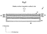
- Fig. 2 is a sectional view illustrating the electronic device with pressing input function in accordance with First embodiment of the present invention.
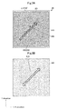
- FIGS. 3A and 3B are plan views of the display panel with pressure sensor in accordance with First embodiment of the present invention.
- FIG. 3A is a plan view of the pressure sensor, and
- FIG. 3B is a plan view of a front polarizing plate.
- an electronic device with pressing input function 1 includes a substantially rectangular parallelepiped-shaped housing 50.
- a front face side of the housing 50 is opened.
- a widthwise direction (horizontal direction) of the housing 50 is defined as an X direction, a lengthwise direction (vertical direction) as a Y direction, a thickness direction as a Z direction.
- a length of the housing 50 in the X direction is smaller than a length of the housing 50 in the Y direction.
- the length in the X direction may be the same as the length in the Y direction, or the length in the X direction may be larger than the length in the Y direction.
- a display panel with pressure sensor 10 and an arithmetic circuit module 60 are disposed in the housing 50.
- the display panel with pressure sensor 10 and the arithmetic circuit module 60 are disposed in this order in the Z direction from an opened surface (display surface) side of the housing 50.
- the display panel with pressure sensor 10 includes a pressure sensor 20 and a display panel 30.
- the display panel 30 includes a flat plate-like liquid crystal panel 301, a front polarizing plate 302, and a rear reflective plate 303.
- a driving current is applied from the outside to the liquid crystal panel 301, changing the alignment of liquid crystal so as to form a predetermined image pattern.
- the front polarizing plate 302 allows only a light wave vibrating in one direction to transmit.
- the direction in which the light transmits is a polarizing direction 910.
- the polarizing direction 910 of the front polarizing plate 302 forms 45 degrees relative to the X direction and the Y direction.
- the rear reflective plate 303 reflects light from the liquid crystal panel 301 toward the liquid crystal panel 301.
- the pressure sensor 20 is disposed between the liquid crystal panel 301 and the front polarizing plate 302 of the display panel 30. As illustrated in FIG. 3A , the pressure sensor 20 includes a flat film-like piezoelectric film 201.
- the electrodes 202, 203 are disposed on both flat plate faces (principal faces) of the piezoelectric film 201.
- the electrodes 202, 203 are formed on the substantially entire flat plate faces of the piezoelectric film 201.
- the piezoelectric film 201 is a film formed of a chiral polymer.
- polylactic acid (PLA) in particular, L-type polylactic acid (PLLA) is used as the chiral polymer.
- PLLA L-type polylactic acid
- the PLLA is uniaxially drawn.
- the PLLA formed of the chiral polymer has a spiral principal chain.
- the PLLA is uniaxially drawn, its molecules are oriented, providing a piezoelectric property.
- the uniaxially drawn PLLA generates electric charge.
- the amount of electric charge generated at this time depends on the displacement of the flat plate faces in the direction orthogonal to the flat plate faces according to the pressing amount.
- the piezoelectric constant of the uniaxially drawn PLLA is extremely high in polymers. Consequently, the displacement caused by pressing can be detected at a high sensitivity.
- the draw ratio is preferably, about 3 to 8 times.
- Thermal treatment after drawing promotes crystallization of the drawn chain of the polylactic acid to improve the piezoelectric constant.
- biaxial drawing can achieve the same effect as that of uniaxial drawing by making the draw ratio of the axes different.
- the substantially same piezoelectric constant can be acquired as in the case of uniaxially drawing 4 times in the first axial direction. That is, the above-mentioned uniaxial drawing direction means the most drawn direction, also including the case where the piezoelectric film is drawn inmultiple directions. Because the uniaxially drawn film tends to tear in the drawing axis direction, the biaxial drawing can somewhat increase the strength of the film.
- the PLLA exhibits the piezoelectric property by molecule orientation processing such as drawing, unlike other polymers such as PVDF and piezoelectric ceramics, polling is not required. That is, the piezoelectric property of the PLLA as a non-ferroelectric substance is not produced by ion polarization as in ferroelectric substances such as PVDF and PZT, and is derived from its characteristic spiral structure of molecules. For this reason, the PLLA does not provide pyroelectricity generated in other ferroelectric piezoelectric substances. Further, the piezoelectric constant of the PVDF varies with time, and may be greatly decreased in some cases, while the piezoelectric constant of the PLLA does not change with time. Consequently, the displacement caused by pressing can be detected at a high sensitivity irrespective of surrounding environment.
- the electrodes 202, 203 are suitably, inorganic electrodes such as ITO, ZnO, Ag nanowire, carbon nanotube, and graphene, or organic electrodes containing polythiophene, polyaniline, or the like as a main component. Use of these materials can achieve a highly translucent conductive pattern.
- the electric charge generated on the piezoelectric film 201 can be acquired as a potential difference, and a piezoelectric detection signal having a voltage value corresponding to the pressing amount can be outputted to the outside.
- the piezoelectric detection signal is outputted to the arithmetic circuit module 60 via wiring not shown.
- the arithmetic circuit module calculates the pressing amount based on the piezoelectric detection signal.
- Such PLLA has birefringence. Specifically, the refractive index of the PLLA in the drawing direction is about 1.47, while the refractive index in the direction orthogonal to the drawing direction is about 1.45. Accordingly, light penetrating the piezoelectric film 201, that is, the pressure sensor 20 generates retardation between the component in the drawing direction and the component (orthogonal component) in the direction orthogonal to the drawing direction.
- the pressure sensor 20 thus configured is a rectangle extending in the X direction and the Y direction that are orthogonal to each other.
- a uniaxial drawing direction 900 of the piezoelectric film 201 of the pressure sensor 20 forms 45 degrees relative to the X direction and the Y direction.
- a polarizing direction 910 of the front polarizing plate 302 is parallel to the uniaxial drawing direction 900 of the piezoelectric film 201.
- an angular difference ⁇ between the uniaxial drawing direction 900 of the piezoelectric film 201 and the polarizing direction of the front polarizing plate 302 is 0 degree (180 degrees).
- the display panel with pressure sensor 10 thus configured and an electronic device with pressing input function 1 enable the operator to view the display screen according to a following principle.
- Light emitted from the display surface (operation surface) of the housing 50 is incident onto the pressure sensor 20 through the front polarizing plate 302.
- the light penetrating the pressure sensor 20 is incident onto the liquid crystal panel 301.
- the light incident onto the liquid crystal panel 301 reflects on the rear reflective plate 303, penetrates the liquid crystal panel 301 again, and then, returns to the front face side.
- this light forms a displayed image having predetermined color and pattern (displayed image-forming light).
- the displayed image-forming light penetrates the pressure sensor 20, and is emitted to the front polarizing plate 302.
- the polarizing direction 910 of the front polarizing plate 302 is parallel to the uniaxial drawing direction 900 of the piezoelectric film 201, only the light component in the polarizing direction 910 of the front polarizing plate 302, that is, in the uniaxial drawing direction 900 of the piezoelectric film 201 penetrates the front polarizing plate 302. Consequently, light emitted to the operation surface through the front polarizing plate 302 is not affected by retardation of the piezoelectric film 201.
- FIGS. 4A and 4B are views illustrating detection characteristics of PLLA used for the pressure sensor.
- FIG. 4A illustrates a bending detection characteristic
- FIG. 4B illustrates a twisting detection characteristic.
- FIG. 4C is an external perspective view of a test plate with which the characteristics in FIGs. 4A and 4B are measured.
- the test plate includes a rectangular flat plate-like base board 90, and rectangular piezoelectric films 91, 92 with electrodes in plan view.
- the base board 90 is formed of an acrylic plate (PMMA) having a length of 150 mm, a width of 70 mm, and a thickness of 2 mm.
- the piezoelectric films 91, 92 each are L-type polylactic acid PLLA having a length of 80 mm, a width of 30 mm, and a thickness of 0.07 mm.
- a piezoelectric stress constant d 14 of the piezoelectric films 91, 92 is 6.7 pC/N, and a tensile elastic constant in the uniaxial drawing direction is 5.9 GPa, and a tensile elastic constant in the direction orthogonal to the uniaxial drawing direction is 3.3 GPa.
- the piezoelectric films 91, 92 are disposed at the substantially center of the base board 90 in a plan view such that their longitudinal directions are aligned.
- the piezoelectric film 91 is disposed on one flat plate face of the base board 90, and the piezoelectric film 92 is disposed on the other flat plate face of the base board 90.
- An uniaxial drawing direction 901 of the piezoelectric film 91 forms 45 degrees relative to the longitudinal direction and the widthwise direction.
- a uniaxial drawing direction 902 of the piezoelectric film 92 is parallel to the longitudinal direction.
- both longitudinal ends of the base board 90 are fixed, and a pressing force is applied to the center of the flat plate faces of the base board 90.
- one longitudinal end of the base board 90 is fixed, and the other longitudinal end is rotated (twisted).
- a horizontal axis of FIG. 4A illustrates a displacement at the center
- a horizontal axis in FIG. 4B illustrates a rotational angle of the free end (the other twisted end) with respect to the fixed end (one fixed end).
- FIG. 4A and FIG. 4B illustrate the amount of electric charge generated by bending or twisting.
- the amount of electric charge generated in the piezoelectric film 91 changes, and the amount of electric charge generated in the piezoelectric film 92 hardly changes.
- the amount of electric charge generated in the piezoelectric film 91 changes depending on dimension and direction of the bending. That is, when the uniaxial drawing direction forms 45 degrees relative to the fixed side, bending and bending amount are detected, and twisting is not detected. In this manner, pressing and pressing amount can be detected without detecting twisting that contributes to another noise.
- the amount of electric charge linearly changes with the pressing amount.
- the amount of electric charge generated in the piezoelectric film 91 hardly changes, and the amount of electric charge generated in the piezoelectric film 92 changes.
- the amount of electric charge generated in the piezoelectric film 92 changes depending on dimension and direction of the twisting. That is, when the uniaxial drawing direction forms 90 degrees relative to the fixed side, twisting and twisting angle are detected, and deformation is not detected.
- the electrode 202 of the pressure sensor 20 can be prevented frombeing exposed on the side of the operation surface. This eliminates the necessity for providing a protective film for the pressure sensor 20 against external environment.
- the pressure sensor 20 is disposed between the front polarizing plate 302 and the liquid crystal panel 301, but the pressure sensor 20 may be disposed between the liquid crystal panel 301 and the rear reflective plate 303.
- the pressure sensor 20 is disposed between the front polarizing plate 302 and the liquid crystal panel 301, only the front polarizing plate 302 is present between the operation surface and the pressure sensor 20. For this reason, upon pressing of the operation surface, the piezoelectric film 201 of the pressure sensor 20 can be greatly bent. This can improve the detection sensitivity of the pressing amount.
- the pressure sensor 20 may be used as a trigger input unit for activating operation. This eliminates the necessity for making a hole in the housing and providing an operational switch, thereby achieving the electronic device with pressing input function 1 having excellent waterproofness and design qualities.
- FIGS. 5 are plan views of another mode of the pressure sensor in accordance with First embodiment of the present invention.
- the uniaxial drawing direction 900 is orthogonal to the polarizing direction 910. That is, the angular difference ⁇ between the uniaxial drawing direction 900 and the polarizing direction 910 is 90 degrees. According to even such aspect, the effect of retardation on the pressure sensor 20 can be suppressed such that the operator can view desired color to be reproduced on the display panel 30 without discoloration.
- the above-mentioned concept that the uniaxial drawing direction 900 is parallel to or orthogonal to the polarizing direction 910 includes the case where the angular difference ⁇ is almost 0 degree or almost 90 degrees, and the allowable scope of the angular difference ⁇ can be appropriately set according to the specification of the electronic device with pressing input function 1, for example, to about ⁇ 5 degrees.
- a display panel with pressure sensor in accordance with Second embodiment of the present invention will be described with reference to figures.
- the basic structure such as the contour and so on of an electronic device with pressing input function in this embodiment is the same as that of the electronic device with pressing input function 1 in First embodiment except for the configuration of a display panel with pressure sensor. Accordingly, only the difference between the display panel with pressure sensor in this embodiment and the display panel with pressure sensor in First embodiment will be specifically described.
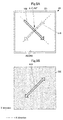
- FIGS. 6A and 6B are plan views of the display panel with pressure sensor in accordance with Second embodiment of the present invention.
- FIG. 6A is a plan view of the pressure sensor
- FIG. 6B is a plan view of a front polarizing plate.
- a polarizing direction 910A is parallel to the first direction.
- a uniaxial drawing direction 900A is parallel to the first direction. That is, the polarizing direction 910A of the front polarizing plate 302A and the uniaxial drawing direction 900A of the piezoelectric film 201A are parallel to the first direction, and are parallel to each other. With such configuration, even the display panel in which the polarizing direction 910A of the front polarizing plate 302A is parallel to the first direction can present desired color to be produced to the operator without discoloration.
- Electrodes 2021, 2022, 2023, and 2024 are formed on one principal face of the pressure sensor 20A.
- the electrodes 2021, 2022, 2023, and 2024 are formed by dividing the electrode 202 in First embodiment along a dividing portion (non-electrode portion) extending in the first direction through the center of the electrode 202 and a dividing portion (non-electrode portion) extending in the second direction.
- the electrode on the other principal face may or may not be divided into the electrodes 2021, 2022, 2023, and 2024.
- the uniaxial drawing direction 900A is parallel to the first direction
- a pressing force is applied to the center of the operation surface, that is, the center of the piezoelectric film 201A
- electric charge that would be compensated and thus, could not be detected with the electrode spreading over the face can be detected.
- the center of the operation surface the center of the piezoelectric film 201A
- electric charge generated in the piezoelectric film 201A varies according to regions where the electrodes 2021, 2022, 2023, and 2024 are disposed, and different amounts of electric charge can be detected.
- the pressing amount can be calculated by adding (adding or subtracting in calculation) the amounts of electric charge detected using the electrodes 2021, 2022, 2023, and 2024 so as not to cause compensation rather than by merely adding the amounts.
- the arithmetic processing module 60 may perform such calculation.
- the configuration in this embodiment enables reliable detection of the pressing amount.
- the electrode pattern on the piezoelectric film 201 based on the configuration in First embodiment and the configuration in Second embodiment, even when the polarizing direction of the front polarizing plate with respect to the housing is any direction, desired color to be reproduced on the display panel can be presented to the operator without discoloration, and the pressing amount can be reliably detected.
- FIG. 7 is a sectional view of the display panel with pressure sensor in accordance with Third embodiment of the present invention.
- FIGS. 8A and 8B are plan views of the display panel with pressure sensor in accordance with Third embodiment of the present invention; FIG. 8A is a plan view of a position detecting sensor, and FIG. 8B is a plan view of a pressure sensor.
- the display panel with pressure sensor 10B in this embodiment includes a position detecting sensor 70.
- the position detecting sensor 70 includes a flat plate-like insulating board 701.
- the insulating board 701 is made of a translucent material having no birefringence.
- a plurality of electrodes 702 are formed on one flat plate face of the insulating board 701.
- the plurality of electrodes 702 are long, and its longitudinal direction corresponds to the Y direction.
- the plurality of electrodes 702 are spaced in the X direction.
- a plurality of electrodes 703 are formed on the other flat plate face of the insulating board 701.
- the plurality of electrodes 703 are long, and its longitudinal direction corresponds to the X direction.
- the plurality of electrodes 703 are spaced in the Y direction.
- the plurality of electrodes 702, 703 are made of a translucent material.
- the position detecting sensor 70 detects a change of capacitance, which is caused when a finger of the operator comes close, with the electrodes 702, 703, and outputs a capacitance detection signal to the arithmetic circuit module 60.
- the arithmetic circuit module 60 detects the operational position based on the combination of the electrodes 702, 703 that detects the capacitance detection signal.
- the position detecting sensor 70 is disposed between the pressure sensor 20 and the front polarizing plate 302. Even with such configuration, as in First embodiment, desired color displayed on the display panel can be presented to the operator. Moreover, the configuration in this embodiment enables detection of the pressing amount as well as the operational position.
- FIG. 9 is a sectional view of the display panel with pressure sensor in accordance with Fourth embodiment of the present invention.
- the display panel with pressure sensor 10C in this embodiment includes a pressure sensor 20C.
- the pressure sensor 20C includes a piezoelectric film 201.
- a piezoelectric detecting electrode 202P and a capacitance detecting electrode 202D are formed on a first flat plate face of the piezoelectric film 201.
- the plurality of piezoelectric detecting electrodes 202P and the plurality of capacitance detecting electrodes 202D are formed so as not to be electrically connected to the capacitance detecting electrodes 202D.
- a piezoelectric detecting electrode 203P and a capacitance detecting electrode 203D are formed on a second flat plate face of the piezoelectric film 201.
- the plurality of piezoelectric detecting electrodes 203P and the plurality of capacitance detecting electrodes 203D are formed so as not to be electrically connected to the capacitance detecting electrodes 203D.
- the piezoelectric detection electrodes 202P, 203P are shaped to be capable of detecting a voltage due to electric charge generated by bending of the piezoelectric film 201.
- the capacitance detecting electrodes 202D, 203D are shaped to be capable of detecting a capacitance change generated from the operation of the operation surface by the operator.
- the piezoelectric detection electrodes 202P, 203P, and the capacitance detecting electrodes 202D, 203D are made of a translucent material.
- the pressure sensor 20C using the single piezoelectric film 201 can detect the pressing amount and the operational position.
- a desired color displayed in the display panel can be offered to the operator.
- the display panel with pressure sensor and the electronic device with pressing input function which are capable of detecting the pressing amount and the operational position, can be made thinner.
- FIG. 10 is a sectional view of the display panel with pressure sensor in accordance with Fifth embodiment of the present invention.
- a buffer member 80 is disposed between the pressure sensor 20 and the liquid crystal panel 301.
- the buffer member 80 is made of an insulating and translucent material having no birefringence.
- the buffer member 80 is made of a material having a low elasticity.
- desired color displayed on the display panel can be presented to the operator.
- the flat plate face can be kept flat and thus, does not obstruct bending of the pressure sensor 20 due to pressing by operation. Therefore, the pressing amount can be detected at a higher sensitivity.
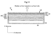
- FIG. 11 is a sectional view of the display panel with pressure sensor in accordance with Sixth embodiment of the present invention.
- the display panel 30t includes a liquid crystal panel 301, a front polarizing plate 302, and a rear polarizing plate 303t.
- a backlight 310 is disposed on the side of the arithmetic circuit module 60 of the display panel 30t.
- a polarizing direction of the rear side polarizing plate 303t is orthogonal to the polarizing direction of the front side polarizing plate 302.
- transmission display panel enables the display panel to present desired color to the operator, as in the above-mentioned embodiments.
- TN liquid crystal having a twist angle of 90 degrees this embodiment can be applied.
- STN liquid crystal having a twist angle of 90 degrees or more for example, the STN liquid crystal having a twist angle of 180 degrees may be used to make the polarizing direction of the rear side polarizing plate parallel to the polarizing direction of the front side polarizing plate.
- PLA or PLLA is used as the piezoelectric film formed of chiral polymer.
- the above-mentioned configuration can be applied to the case of using another piezoelectric film having birefringence, such as PDLA.
- piezoelectric film pressure sensor
- a plurality of the piezoelectric films pressure sensors
- the piezoelectric films may be disposed such that the uniaxial drawing direction of each piezoelectric film is parallel to the polarizing direction of the front polarizing plate or the rear polarizing plate.
- the pressure sensor is disposed between the front polarizing plate and the liquid crystal panel.
- the pressure sensor may be disposed opposite to the liquid crystal panel across the front polarizing plate, achieving the same effect.
Landscapes
- Physics & Mathematics (AREA)
- Engineering & Computer Science (AREA)
- General Physics & Mathematics (AREA)
- Theoretical Computer Science (AREA)
- General Engineering & Computer Science (AREA)
- Optics & Photonics (AREA)
- Nonlinear Science (AREA)
- Human Computer Interaction (AREA)
- Crystallography & Structural Chemistry (AREA)
- Chemical & Material Sciences (AREA)
- Mathematical Physics (AREA)
- Liquid Crystal (AREA)
- Position Input By Displaying (AREA)
- Devices For Indicating Variable Information By Combining Individual Elements (AREA)
Abstract

Description
- The present invention relates to a display panel with pressure sensor capable of detecting pressing a display screen with a finger of the like, and an electronic device with pressing input function provided with the display panel with pressure sensor.
- Various electronic devices provided with a thin display panel such as a liquid crystal display capable of receiving an operational input on its display surface have been proposed. For example, Patent Literature 1 discloses a touch sensor for detecting an operational position, which is disposed on a front face of a display panel. When an operator touches an operation surface, the touch sensor detects a touch position, and the electronic device executes processing according to the detected operational position.
- In the case where such conventional electronic device with touch sensor includes a display panel requiring a polarizing plate such as a liquid crystal panel, components constituting the electronic device are disposed as follows.
- A front polarizing plate is disposed on the operation surface (outermost face). A touch panel is disposed on the opposite side of the front polarizing plate to the operation surface. A liquid crystal panel formed of a pair of glasses that sandwiches liquid crystal therebetween is disposed on the opposite side of the touch panel to the front polarizing plate. A rear polarizing plate is disposed on the opposite side of the liquid crystal panel to the touch panel. That is, the touch panel is disposed between the front polarizing plate and the rear polarizing plate.
- With the above-mentioned structure, in the case of a transmission liquid crystal display, light from a backlight disposed on the rear face of the rear polarizing plate penetrates the rear polarizing plate, the liquid crystal panel, the touch panel, and the front polarizing plate in this order and then, is emitted to the operation surface. In the case of a reflection liquid crystal display, for example, a reflective plate is provided in place of the rear polarizing plate, and light incident from the operation surf ace penetrates the frontpolarizingplate, the touch panel, the liquid crystal panel, the reflective plate, the liquid crystal panel, the touch panel, and the front polarizing plate in this order and then, returns to the operation surface.
- The front polarizing plate and the rear polarizing plate have the property of transmitting only a wave (light wave) vibrating in a certain direction. The direction in which the wave is transmitted is a polarizing direction. Accordingly, the polarizing direction of the front polarizing plate, the polarizing direction of the rear polarizing plate, and optical characteristics of the liquid crystal panel are combined to set contrast and transmittance of the liquid crystal display and improve appearance of the display screen.
- Japanese Patent Unexamined Publication No.
2012-230657 - However, the above-mentioned conventional electronic device with the thin display panel has a following problem.
- Currently, a pressure sensor is composed of a piezoelectric element formed of a chiral polymer to detect pressing onto the operation surface. However, the piezoelectric element formed of the chiral polymer has birefringence. For example, the refractive index of a wave vibrating in a direction parallel to the drawing direction of a uniaxially drawn L-type polylactic acid (PLLA) is 1.47. The refractive index of a wave vibrating in a direction vertical to the drawing direction of the uniaxially drawn L-type polylactic acid (PLLA) is 1.45. This is the retardation property.
- In corporation such pressure sensor into the above-mentioned thin display panel, when the transmission display panel is disposed between the front polarizing plate and the rear polarizing plate, and the reflective display panel is disposed between two front polarizing plates along the light guiding direction. With such configuration, a light wave disperses in two directions due to birefringence of the pressure sensor, and the light wave components dispersing in the two directions are incident on the front polarizing plate. Then, unlike the configuration without the pressure sensor, the two components penetrate the front polarizing plate and then, interfere with each other to change the color of the emitted light. This leads to the problem that desired image color cannot be acquired. Although this problem is avoided by mounting the pressure sensor on the front polarizing plate, when the user wearing polarizing sunglasses views the screen, crossed nicols is caused by the front polarizing plate of the thin display panel and polarization of the sunglasses, disadvantageously changing the color of the screen.
- Therefore, an obj ect of the present invention is to provide a display panel with pressure sensor capable of reproducing desired color even in the presence of a pressure sensor using a piezoelectric element formed of a chiral polymer.
- A display panel with pressure sensor according to the present invention includes a display panel having an image forming panel for controlling light emitted to a front face side to form a displayed image and a front polarizing plate disposed on the front face side of the image forming panel, and a pressure sensor having a piezoelectric film formed of a chiral polymer. In the display panel with pressure sensor, the pressure sensor is disposed relative to the display panel such that a polarizing direction of the piezoelectric film is parallel to or orthogonal to a polarizing direction of the front polarizing plate.
- With this configuration, since only one of two components of a light wave dispersing on the piezoelectric film penetrates the front polarizing plate, the color of the light wave does not change even after the light penetrates the front polarizing plate.
- Preferably, the display panel with pressure sensor according to the present invention has either of following configurations. The pressure sensor is disposed opposite to the image forming panel across the front polarizing plate. The pressure sensor is disposed between the front polarizing plate and the image forming panel.
- According to the present invention, since the pressure sensor is disposed near the operation surface, the pressure detection sensitivity can be increased. Further, the front polarizing plate can be used as a protective layer for the pressure sensor.
- Preferably, the display panel with pressure sensor of the present invention has a following configuration. The chiral polymer forming the piezoelectric film is polylactic acid. The polylactic acid is at least uniaxially drawn, and the drawing direction is parallel to or orthogonal to a polarizing direction of the front polarizing plate.
- With this configuration, polylactic acid is used for the piezoelectric film. For the polylactic acid, a refractive index in the uniaxial drawing direction as the main drawing direction is different from a refractive index in the direction orthogonal to the uniaxial drawing direction. Accordingly, discoloration of display can be prevented by making the uniaxial drawing direction parallel to or orthogonal to the polarizing direction. Further, use of the uniaxially drawn polylactic acid can provide a pressure sensor having a high detection sensitivity of the pressing amount (pressing amount of the operation surface) and an excellent temperature characteristic.
- According to the present invention, a buffer member is preferably provided between the pressure sensor and the image forming panel. This configuration can suppress the image forming panel from obstructing displacement of the piezoelectric film due to pressing. This can improve the detection sensitivity of the pressure sensor.
- In the display panel with pressure sensor of the present invention, the pressure sensor may have a position-detecting sensor function of detecting a touch position. This configuration enables detection of the pressing amount as well as the touch position.
- An electronic device with pressing input function of the present invention includes the display panel with pressure sensor according to any one of the display panels, and arithmetic unit that detects a pressing amount based on a detection signal of the pressure sensor, and a housing that is opened to a display surface and accommodates the display panel with pressure sensor and the arithmetic unit.
- With this configuration, even the electronic device provided with the pressure sensor using the piezoelectric film having birefringence enables the operator to view light emitted from the display panel and the front polarizing plate, without changing the color of the light.
- According to the present invention, even the display panel including the pressure sensor having birefringence can reproduce a desired color.
-
-
FIG. 1 is an external perspective view of an electronic device with pressing input function in accordance with First embodiment of the present invention. -
FIG. 2 is a sectional view of an electronic device with pressing input function in accordance with First embodiment of the present invention. -
FIGS. 3A and 3B are plan views of a display panel with pressure sensor in accordance with First embodiment of the present invention. -
FIGS. 4A to 4C are views illustrating detection characteristics of PLLA used for the pressure sensor. -
FIGS. 5 are plan views of another mode of the pressure sensor in accordance with First embodiment of the present invention. -
FIGS. 6A and 6B are plan views of a display panel with pressure sensor in accordance with Second embodiment of the present invention. -
FIG. 7 is a sectional view of an electronic device with pressing input function in accordance with Third embodiment of the present invention. -
FIGS. 8A and 8B are plan views of a display panel with pressure sensor in accordance with Third embodiment of the present invention. -
FIG. 9 is a sectional view of a display panel with pressure sensor in accordance with Fourth embodiment of the present invention. -
FIG. 10 is a sectional view of a display panel with pressure sensor in accordance with Fifth embodiment of the present invention. -
FIG. 11 is a sectional view of a display panel with pressure sensor in accordance with Sixth embodiment of the present invention. - An electronic device with pressing input function and a display panel with pressure sensor provided in the electronic device in accordance with First embodiment of the present invention will be described below with reference to the drawings.
Fig. 1 is an external perspective view of an electronic device with pressing input function in accordance with First embodiment of the present invention.Fig. 2 is a sectional view illustrating the electronic device with pressing input function in accordance with First embodiment of the present invention.FIGS. 3A and 3B are plan views of the display panel with pressure sensor in accordance with First embodiment of the present invention.FIG. 3A is a plan view of the pressure sensor, andFIG. 3B is a plan view of a front polarizing plate. - As illustrated in
Fig. 1 , an electronic device with pressing input function 1 includes a substantially rectangular parallelepiped-shapedhousing 50. A front face side of thehousing 50 is opened. Hereinafter, a widthwise direction (horizontal direction) of thehousing 50 is defined as an X direction, a lengthwise direction (vertical direction) as a Y direction, a thickness direction as a Z direction. In this embodiment, a length of thehousing 50 in the X direction is smaller than a length of thehousing 50 in the Y direction. However, the length in the X direction may be the same as the length in the Y direction, or the length in the X direction may be larger than the length in the Y direction. - As illustrated in
FIG. 2 , a display panel withpressure sensor 10 and anarithmetic circuit module 60 are disposed in thehousing 50. The display panel withpressure sensor 10 and thearithmetic circuit module 60 are disposed in this order in the Z direction from an opened surface (display surface) side of thehousing 50. The display panel withpressure sensor 10 includes apressure sensor 20 and adisplay panel 30. - The
display panel 30 includes a flat plate-likeliquid crystal panel 301, a frontpolarizing plate 302, and a rearreflective plate 303. A driving current is applied from the outside to theliquid crystal panel 301, changing the alignment of liquid crystal so as to form a predetermined image pattern. The frontpolarizing plate 302 allows only a light wave vibrating in one direction to transmit. The direction in which the light transmits is apolarizing direction 910. For example, as illustrated inFIGs. 3A and 3B , on thedisplay panel 30 in this embodiment, thepolarizing direction 910 of the frontpolarizing plate 302 forms 45 degrees relative to the X direction and the Y direction. The rearreflective plate 303 reflects light from theliquid crystal panel 301 toward theliquid crystal panel 301. - The
pressure sensor 20 is disposed between theliquid crystal panel 301 and the frontpolarizing plate 302 of thedisplay panel 30. As illustrated inFIG. 3A , thepressure sensor 20 includes a flat film-likepiezoelectric film 201. Theelectrodes piezoelectric film 201. Theelectrodes piezoelectric film 201. - The
piezoelectric film 201 is a film formed of a chiral polymer. In this embodiment, polylactic acid (PLA), in particular, L-type polylactic acid (PLLA) is used as the chiral polymer. The PLLA is uniaxially drawn. - The PLLA formed of the chiral polymer has a spiral principal chain. When the PLLA is uniaxially drawn, its molecules are oriented, providing a piezoelectric property. By pressing the flat plate faces of the piezoelectric film, the uniaxially drawn PLLA generates electric charge. The amount of electric charge generated at this time depends on the displacement of the flat plate faces in the direction orthogonal to the flat plate faces according to the pressing amount.
- The piezoelectric constant of the uniaxially drawn PLLA is extremely high in polymers. Consequently, the displacement caused by pressing can be detected at a high sensitivity.
- The draw ratio is preferably, about 3 to 8 times. Thermal treatment after drawing promotes crystallization of the drawn chain of the polylactic acid to improve the piezoelectric constant. It is noted that biaxial drawing can achieve the same effect as that of uniaxial drawing by making the draw ratio of the axes different. For example, in the case of biaxially drawing the film 8 times in a first axial direction and twice in a second axial direction orthogonal to the first axial direction, the substantially same piezoelectric constant can be acquired as in the case of uniaxially drawing 4 times in the first axial direction. That is, the above-mentioned uniaxial drawing direction means the most drawn direction, also including the case where the piezoelectric film is drawn inmultiple directions. Because the uniaxially drawn film tends to tear in the drawing axis direction, the biaxial drawing can somewhat increase the strength of the film.
- Because the PLLA exhibits the piezoelectric property by molecule orientation processing such as drawing, unlike other polymers such as PVDF and piezoelectric ceramics, polling is not required. That is, the piezoelectric property of the PLLA as a non-ferroelectric substance is not produced by ion polarization as in ferroelectric substances such as PVDF and PZT, and is derived from its characteristic spiral structure of molecules. For this reason, the PLLA does not provide pyroelectricity generated in other ferroelectric piezoelectric substances. Further, the piezoelectric constant of the PVDF varies with time, and may be greatly decreased in some cases, while the piezoelectric constant of the PLLA does not change with time. Consequently, the displacement caused by pressing can be detected at a high sensitivity irrespective of surrounding environment.
- Further, the PLLA has a very low relative permittivity of about 2.5 and thus, given that d is piezoelectric constant and εT is dielectric constant, a piezoelectric output constant (= piezoelectric g constant, g = d/εT) becomes large. The piezoelectric g constant of the PVDF having a dielectric constant ε33 T = 13 × ε0 and a piezoelectric constant d31 = 25 pC/N becomes g31 = 0.2172 Vm/N according to the above-mentioned equation. When converting the piezoelectric g constant of the PLLA having a piezoelectric constant d14 = 10 pC/N into g31, due to d14 = 2 × d31, d31 = 5 pC/N, and the piezoelectric g constant becomes g31 = 0.2258 Vm/N. Therefore, the PLLA having the piezoelectric constant d14 = 10pC/N can achieve the same detection sensitivity of the pressing amount as that of the PVDF. The inventors of this application experimentally obtained PLLA having d14 = 15 to 20 pC/N. Using the PLLA can detect pressing at a much higher sensitivity.
- The
electrodes electrodes piezoelectric film 201 can be acquired as a potential difference, and a piezoelectric detection signal having a voltage value corresponding to the pressing amount can be outputted to the outside. The piezoelectric detection signal is outputted to thearithmetic circuit module 60 via wiring not shown. The arithmetic circuit module calculates the pressing amount based on the piezoelectric detection signal. - Such PLLA has birefringence. Specifically, the refractive index of the PLLA in the drawing direction is about 1.47, while the refractive index in the direction orthogonal to the drawing direction is about 1.45. Accordingly, light penetrating the
piezoelectric film 201, that is, thepressure sensor 20 generates retardation between the component in the drawing direction and the component (orthogonal component) in the direction orthogonal to the drawing direction. - The
pressure sensor 20 thus configured is a rectangle extending in the X direction and the Y direction that are orthogonal to each other. Auniaxial drawing direction 900 of thepiezoelectric film 201 of thepressure sensor 20 forms 45 degrees relative to the X direction and the Y direction. - Accordingly, as illustrated in
FIG. 3A , when the display panel withpressure sensor 10 is viewed from the display surface, apolarizing direction 910 of the frontpolarizing plate 302 is parallel to theuniaxial drawing direction 900 of thepiezoelectric film 201. In other words, an angular difference Δθ between theuniaxial drawing direction 900 of thepiezoelectric film 201 and the polarizing direction of the frontpolarizing plate 302 is 0 degree (180 degrees). - The display panel with
pressure sensor 10 thus configured and an electronic device with pressing input function 1 enable the operator to view the display screen according to a following principle. Light emitted from the display surface (operation surface) of thehousing 50 is incident onto thepressure sensor 20 through the frontpolarizing plate 302. The light penetrating thepressure sensor 20 is incident onto theliquid crystal panel 301. The light incident onto theliquid crystal panel 301 reflects on the rearreflective plate 303, penetrates theliquid crystal panel 301 again, and then, returns to the front face side. In combination with the frontpolarizing plate 302, this light forms a displayed image having predetermined color and pattern (displayed image-forming light). The displayed image-forming light penetrates thepressure sensor 20, and is emitted to the frontpolarizing plate 302. - Since the
polarizing direction 910 of the frontpolarizing plate 302 is parallel to theuniaxial drawing direction 900 of thepiezoelectric film 201, only the light component in thepolarizing direction 910 of the frontpolarizing plate 302, that is, in theuniaxial drawing direction 900 of thepiezoelectric film 201 penetrates the frontpolarizing plate 302. Consequently, light emitted to the operation surface through the frontpolarizing plate 302 is not affected by retardation of thepiezoelectric film 201. - Therefore, even when the
pressure sensor 20 is provided, the operator can view desired color to be reproduced on thedisplay panel 30 without discoloration. - Moreover, the configuration in this embodiment can further increase the detection sensitivity of the pressing amount.
FIGS. 4A and 4B are views illustrating detection characteristics of PLLA used for the pressure sensor.FIG. 4A illustrates a bending detection characteristic, andFIG. 4B illustrates a twisting detection characteristic.FIG. 4C is an external perspective view of a test plate with which the characteristics inFIGs. 4A and 4B are measured. - As illustrated in
FIG. 4C , the test plate includes a rectangular flat plate-like base board 90, and rectangularpiezoelectric films base board 90 is formed of an acrylic plate (PMMA) having a length of 150 mm, a width of 70 mm, and a thickness of 2 mm. Thepiezoelectric films piezoelectric films - The
piezoelectric films base board 90 in a plan view such that their longitudinal directions are aligned. Thepiezoelectric film 91 is disposed on one flat plate face of thebase board 90, and thepiezoelectric film 92 is disposed on the other flat plate face of thebase board 90. - An
uniaxial drawing direction 901 of thepiezoelectric film 91 forms 45 degrees relative to the longitudinal direction and the widthwise direction. Auniaxial drawing direction 902 of thepiezoelectric film 92 is parallel to the longitudinal direction. - In measuring the bending detection characteristic, both longitudinal ends of the
base board 90 are fixed, and a pressing force is applied to the center of the flat plate faces of thebase board 90. In measuring the twisting detection characteristic, one longitudinal end of thebase board 90 is fixed, and the other longitudinal end is rotated (twisted). A horizontal axis ofFIG. 4A illustrates a displacement at the center, and a horizontal axis inFIG. 4B illustrates a rotational angle of the free end (the other twisted end) with respect to the fixed end (one fixed end).FIG. 4A and FIG. 4B illustrate the amount of electric charge generated by bending or twisting. - As illustrated in
FIG. 4A , when thebase board 90 bends, the amount of electric charge generated in thepiezoelectric film 91 changes, and the amount of electric charge generated in thepiezoelectric film 92 hardly changes. The amount of electric charge generated in thepiezoelectric film 91 changes depending on dimension and direction of the bending. That is, when the uniaxial drawing direction forms 45 degrees relative to the fixed side, bending and bending amount are detected, and twisting is not detected. In this manner, pressing and pressing amount can be detected without detecting twisting that contributes to another noise. The amount of electric charge linearly changes with the pressing amount. - As illustrated in
FIG. 4B , when thebase board 90 twists, the amount of electric charge generated in thepiezoelectric film 91 hardly changes, and the amount of electric charge generated in thepiezoelectric film 92 changes. The amount of electric charge generated in thepiezoelectric film 92 changes depending on dimension and direction of the twisting. That is, when the uniaxial drawing direction forms 90 degrees relative to the fixed side, twisting and twisting angle are detected, and deformation is not detected. - Another experiment demonstrates that, as the angle that the uniaxial drawing direction forms relative to the fixed side is shifted from 45 degrees, the amount of electric charge generated according to the shifted amount lowers.
- By fixing each side of the
pressure sensor 20 to thehousing 50 and setting theuniaxial drawing direction 900 to the direction of 45 degrees in plan view, the above-mentioned effect on the displayed image can be achieved, pressing can be detected at a high sensitivity and pressing amount can be detected with high accuracy. Moreover, wrong detection caused by other stresses such as twisting can be suppressed. - By disposing the insulating
front polarizing plate 302 on the side of the operation surface of thepressure sensor 20 as described above, theelectrode 202 of thepressure sensor 20 can be prevented frombeing exposed on the side of the operation surface. This eliminates the necessity for providing a protective film for thepressure sensor 20 against external environment. - In this embodiment, the
pressure sensor 20 is disposed between the frontpolarizing plate 302 and theliquid crystal panel 301, but thepressure sensor 20 may be disposed between theliquid crystal panel 301 and the rearreflective plate 303. However, when thepressure sensor 20 is disposed between the frontpolarizing plate 302 and theliquid crystal panel 301, only the frontpolarizing plate 302 is present between the operation surface and thepressure sensor 20. For this reason, upon pressing of the operation surface, thepiezoelectric film 201 of thepressure sensor 20 can be greatly bent. This can improve the detection sensitivity of the pressing amount. - Using such configuration, the
pressure sensor 20 may be used as a trigger input unit for activating operation. This eliminates the necessity for making a hole in the housing and providing an operational switch, thereby achieving the electronic device with pressing input function 1 having excellent waterproofness and design qualities. - With the above-mentioned configuration, the
uniaxial drawing direction 900 of thepiezoelectric film 201 is parallel to thepolarizing direction 910 of the frontpolarizing plate 302, but these directions may have relationship as illustrated inFIGS. 5. FIGS. 5 are plan views of another mode of the pressure sensor in accordance with First embodiment of the present invention. - In the mode illustrated in
FIGS. 5 , theuniaxial drawing direction 900 is orthogonal to thepolarizing direction 910. That is, the angular difference Δθ between theuniaxial drawing direction 900 and thepolarizing direction 910 is 90 degrees. According to even such aspect, the effect of retardation on thepressure sensor 20 can be suppressed such that the operator can view desired color to be reproduced on thedisplay panel 30 without discoloration. - The above-mentioned concept that the
uniaxial drawing direction 900 is parallel to or orthogonal to thepolarizing direction 910 includes the case where the angular difference Δθ is almost 0 degree or almost 90 degrees, and the allowable scope of the angular difference Δθ can be appropriately set according to the specification of the electronic device with pressing input function 1, for example, to about ±5 degrees. - Next, a display panel with pressure sensor in accordance with Second embodiment of the present invention will be described with reference to figures. The basic structure such as the contour and so on of an electronic device with pressing input function in this embodiment is the same as that of the electronic device with pressing input function 1 in First embodiment except for the configuration of a display panel with pressure sensor. Accordingly, only the difference between the display panel with pressure sensor in this embodiment and the display panel with pressure sensor in First embodiment will be specifically described.
-
FIGS. 6A and 6B are plan views of the display panel with pressure sensor in accordance with Second embodiment of the present invention.FIG. 6A is a plan view of the pressure sensor, andFIG. 6B is a plan view of a front polarizing plate. - As illustrated in
FIG. 6B , in a frontpolarizing plate 302A of the display panel with pressure sensor in this embodiment, apolarizing direction 910A is parallel to the first direction. - In the
piezoelectric film 201 of thepressure sensor 20A, auniaxial drawing direction 900A is parallel to the first direction. That is, thepolarizing direction 910A of the frontpolarizing plate 302A and theuniaxial drawing direction 900A of thepiezoelectric film 201A are parallel to the first direction, and are parallel to each other. With such configuration, even the display panel in which thepolarizing direction 910A of the frontpolarizing plate 302A is parallel to the first direction can present desired color to be produced to the operator without discoloration. - Four
electrodes pressure sensor 20A. Theelectrodes electrode 202 in First embodiment along a dividing portion (non-electrode portion) extending in the first direction through the center of theelectrode 202 and a dividing portion (non-electrode portion) extending in the second direction. Though not illustrated, the electrode on the other principal face (electrode corresponding to theelectrode 203 in First embodiment) may or may not be divided into theelectrodes - With such configuration, although the
uniaxial drawing direction 900A is parallel to the first direction, when a pressing force is applied to the center of the operation surface, that is, the center of thepiezoelectric film 201A, electric charge that would be compensated and thus, could not be detected with the electrode spreading over the face can be detected. Specifically, when the center of the operation surface (the center of thepiezoelectric film 201A) is pressed, electric charge generated in thepiezoelectric film 201A varies according to regions where theelectrodes electrodes arithmetic processing module 60 may perform such calculation. - Even when the polarizing direction of the front polarizing plate of the display panel is not 45 degrees, the configuration in this embodiment enables reliable detection of the pressing amount. By appropriately setting the electrode pattern on the
piezoelectric film 201 based on the configuration in First embodiment and the configuration in Second embodiment, even when the polarizing direction of the front polarizing plate with respect to the housing is any direction, desired color to be reproduced on the display panel can be presented to the operator without discoloration, and the pressing amount can be reliably detected. - Next, a display panel with pressure sensor in accordance with Third embodiment of the present invention will be described with reference to figures. The basic structure such as the contour and so on of an electronic device with
pressing input function 1B in this embodiment is the same as that of the electronic device with pressing input function 1 in First embodiment except for the configuration of a display panel withpressure sensor 10B. Accordingly, only the difference between the display panel withpressure sensor 10B and the display panel withpressure sensor 10 in First embodiment will be specifically described.FIG. 7 is a sectional view of the display panel with pressure sensor in accordance with Third embodiment of the present invention.FIGS. 8A and 8B are plan views of the display panel with pressure sensor in accordance with Third embodiment of the present invention;FIG. 8A is a plan view of a position detecting sensor, andFIG. 8B is a plan view of a pressure sensor. - As illustrated in
FIG. 7 , the display panel withpressure sensor 10B in this embodiment includes aposition detecting sensor 70. Theposition detecting sensor 70 includes a flat plate-like insulatingboard 701. The insulatingboard 701 is made of a translucent material having no birefringence. As illustrated inFIG. 8A , a plurality ofelectrodes 702 are formed on one flat plate face of the insulatingboard 701. The plurality ofelectrodes 702 are long, and its longitudinal direction corresponds to the Y direction. The plurality ofelectrodes 702 are spaced in the X direction. A plurality ofelectrodes 703 are formed on the other flat plate face of the insulatingboard 701. The plurality ofelectrodes 703 are long, and its longitudinal direction corresponds to the X direction. The plurality ofelectrodes 703 are spaced in the Y direction. Like theelectrodes pressure sensor 20, the plurality ofelectrodes - The
position detecting sensor 70 detects a change of capacitance, which is caused when a finger of the operator comes close, with theelectrodes arithmetic circuit module 60. Thearithmetic circuit module 60 detects the operational position based on the combination of theelectrodes - As illustrated in
FIG. 7 , theposition detecting sensor 70 is disposed between thepressure sensor 20 and the frontpolarizing plate 302. Even with such configuration, as in First embodiment, desired color displayed on the display panel can be presented to the operator. Moreover, the configuration in this embodiment enables detection of the pressing amount as well as the operational position. - Next, a display panel with pressure sensor in accordance with Fourth embodiment of the present invention will be described with reference to figures. The basic structure such as the contour and so on of an electronic device with
pressing input function 1C in this embodiment is the same as that of the electronic device withpressing input function 1B in Third embodiment except for the configuration of a display panel with pressure sensor 10C. Accordingly, only the difference between the display panel with pressure sensor 10C and the display panel withpressure sensor 10B in Third embodiment will be specifically described.FIG. 9 is a sectional view of the display panel with pressure sensor in accordance with Fourth embodiment of the present invention. - The display panel with pressure sensor 10C in this embodiment includes a
pressure sensor 20C. Thepressure sensor 20C includes apiezoelectric film 201. - A piezoelectric detecting
electrode 202P and acapacitance detecting electrode 202D are formed on a first flat plate face of thepiezoelectric film 201. The plurality of piezoelectric detectingelectrodes 202P and the plurality ofcapacitance detecting electrodes 202D are formed so as not to be electrically connected to thecapacitance detecting electrodes 202D. - A piezoelectric detecting
electrode 203P and acapacitance detecting electrode 203D are formed on a second flat plate face of thepiezoelectric film 201. The plurality of piezoelectric detectingelectrodes 203P and the plurality ofcapacitance detecting electrodes 203D are formed so as not to be electrically connected to thecapacitance detecting electrodes 203D. - The
piezoelectric detection electrodes piezoelectric film 201. Thecapacitance detecting electrodes - The
piezoelectric detection electrodes capacitance detecting electrodes - With such configuration, the
pressure sensor 20C using the singlepiezoelectric film 201 can detect the pressing amount and the operational position. - With such configuration, as in each of the embodiments, a desired color displayed in the display panel can be offered to the operator. Further, the display panel with pressure sensor and the electronic device with pressing input function, which are capable of detecting the pressing amount and the operational position, can be made thinner.
- Next, a display panel with pressure sensor in accordance with Fifth embodiment of the present invention will be described with reference to figures. The basic structure such as the contour and so on of an electronic device with
pressing input function 1D in this embodiment is the same as that of the electronic device with pressing input function 1 in First embodiment except for the configuration of a display panel withpressure sensor 10D. Accordingly, only the difference between the display panel withpressure sensor 10D and the display panel withpressure sensor 10 in First embodiment will be specifically described.FIG. 10 is a sectional view of the display panel with pressure sensor in accordance with Fifth embodiment of the present invention. - In the display panel with
pressure sensor 10D, abuffer member 80 is disposed between thepressure sensor 20 and theliquid crystal panel 301. Thebuffer member 80 is made of an insulating and translucent material having no birefringence. Thebuffer member 80 is made of a material having a low elasticity. - With even such configuration, as in the above-mentioned embodiments, desired color displayed on the display panel can be presented to the operator. Moreover, since providing the
buffer member 80 increases the operation surface, even when thepressure sensor 20 has a large area, the flat plate face can be kept flat and thus, does not obstruct bending of thepressure sensor 20 due to pressing by operation. Therefore, the pressing amount can be detected at a higher sensitivity. - Next, a display panel with pressure sensor in accordance with Sixth embodiment of the present invention will be described with reference to a figure. The basic structure such as the contour and so on of an electronic device with
pressing input function 1E in this embodiment is the same as the electronic device with pressing input function 1 in First embodiment except that adisplay panel 30t is a transmission display panel.FIG. 11 is a sectional view of the display panel with pressure sensor in accordance with Sixth embodiment of the present invention. - As illustrated in
FIG. 11 , thedisplay panel 30t includes aliquid crystal panel 301, a frontpolarizing plate 302, and a rearpolarizing plate 303t. Abacklight 310 is disposed on the side of thearithmetic circuit module 60 of thedisplay panel 30t. A polarizing direction of the rearside polarizing plate 303t is orthogonal to the polarizing direction of the frontside polarizing plate 302. - Even such transmission display panel enables the display panel to present desired color to the operator, as in the above-mentioned embodiments. For TN liquid crystal having a twist angle of 90 degrees, this embodiment can be applied. For STN liquid crystal having a twist angle of 90 degrees or more, for example, the STN liquid crystal having a twist angle of 180 degrees may be used to make the polarizing direction of the rear side polarizing plate parallel to the polarizing direction of the front side polarizing plate.
- In the above-mentioned embodiments, PLA or PLLA is used as the piezoelectric film formed of chiral polymer. However, the above-mentioned configuration can be applied to the case of using another piezoelectric film having birefringence, such as PDLA.
- One piezoelectric film (pressure sensor) is used in the above-mentioned embodiments, but a plurality of the piezoelectric films (pressure sensors) may be stacked. In this case, the piezoelectric films may be disposed such that the uniaxial drawing direction of each piezoelectric film is parallel to the polarizing direction of the front polarizing plate or the rear polarizing plate. Through the use of the piezoelectric films (pressure sensors), by adding up electric charge (voltage) generated in the films so as not to cause compensation, the entire amount of detected electric charge (voltage) can be increased.
- In the above-mentioned embodiments, the pressure sensor is disposed between the front polarizing plate and the liquid crystal panel. However, the pressure sensor may be disposed opposite to the liquid crystal panel across the front polarizing plate, achieving the same effect.
-
- 1, 1B, 1C, 1D, 1E electronic device with pressing input function
- 10, 10B, 10C, 10D, 10E display panel with pressure sensor
- 20, 20A pressure sensor
- 30, 30t display panel
- 50 housing
- 60 arithmetic circuit module
- 70 position detecting sensor
- 80 buffer member
- 201, 201A piezoelectric film
- 202, 203, 2021, 2022, 2023, 2024 electrode
- 202P, 203P piezoelectric detecting electrode
- 202D, 203D capacitance detecting electrode
- 301 liquid crystal panel
- 302, 302A front polarizing plate
- 303 rear reflective plate
- 701 insulating board
- 702, 703 electrode
Claims (7)
- A display panel with pressure sensor comprising:a display panel including an image formingpanel configured to control light emitted to a front face side to form a displayed image, and a front polarizing plate disposed on the front face side of the image forming panel; anda pressure sensor including a piezoelectric film formed of a chiral polymer, whereinthe pressure sensor is disposed relative to the display panel such that a polarizing direction of the piezoelectric film is parallel to or orthogonal to a polarizing direction of the front polarizing plate.
- The display panel with pressure sensor according to claim 1, wherein
the pressure sensor is disposed opposite to the image forming panel across the front polarizing plate. - The display panel with pressure sensor according to claim 1, wherein
the pressure sensor is disposed between the front polarizing plate and the image forming panel. - The display panel with pressure sensor according to any one of claims 1 to 3, wherein
the chiral polymer forming the piezoelectric film is polylactic acid,
the polylactic acid is at least uniaxially drawn, and
the drawing direction is parallel to or orthogonal to a polarizing direction of the front polarizing plate. - The display panel with pressure sensor according to any one of claims 1 to 4, further comprising a buffer member between the pressure sensor and the image forming panel.
- The display panel with touch sensor according to any one of claims 1 to 5, wherein
The pressure sensor has a position-detecting sensor function of detecting a touch position. - An electronic device with pressing input function comprising:A display panel with pressure sensor according to any one of claims 1 to 6;An arithmetic unit configured to detect a pressing amount based on a detection signal from the pressure sensor; andA housing opened to a display surface, the housing being configured to accommodate the display panel with pressure sensor and the arithmetic unit.
Applications Claiming Priority (2)
| Application Number | Priority Date | Filing Date | Title |
|---|---|---|---|
| JP2013110646 | 2013-05-27 | ||
| PCT/JP2014/062773 WO2014192541A1 (en) | 2013-05-27 | 2014-05-14 | Display panel with pressing sensor, and electronic device with pressing input function |
Publications (3)
| Publication Number | Publication Date |
|---|---|
| EP3007041A1 true EP3007041A1 (en) | 2016-04-13 |
| EP3007041A4 EP3007041A4 (en) | 2017-03-29 |
| EP3007041B1 EP3007041B1 (en) | 2022-09-07 |
Family
ID=51988577
Family Applications (1)
| Application Number | Title | Priority Date | Filing Date |
|---|---|---|---|
| EP14804556.0A Active EP3007041B1 (en) | 2013-05-27 | 2014-05-14 | Display panel with pressing sensor, and electronic device with pressing input function |
Country Status (5)
| Country | Link |
|---|---|
| US (1) | US10503305B2 (en) |
| EP (1) | EP3007041B1 (en) |
| JP (1) | JP6069500B2 (en) |
| CN (1) | CN105229579B (en) |
| WO (1) | WO2014192541A1 (en) |
Cited By (1)
| Publication number | Priority date | Publication date | Assignee | Title |
|---|---|---|---|---|
| AT521772B1 (en) * | 2018-10-29 | 2020-05-15 | Joanneum Res Forschungsgmbh | Sensor device |
Families Citing this family (24)
| Publication number | Priority date | Publication date | Assignee | Title |
|---|---|---|---|---|
| WO2013165601A1 (en) | 2012-05-03 | 2013-11-07 | Yknots Industries Llc | Moment compensated bending beam sensor for load measurement on platform supported by bending beams |
| US9952703B2 (en) | 2013-03-15 | 2018-04-24 | Apple Inc. | Force sensing of inputs through strain analysis |
| CN105684177B (en) * | 2013-10-28 | 2019-05-21 | 苹果公司 | Piezo-Based Force Sensing |
| AU2015100011B4 (en) | 2014-01-13 | 2015-07-16 | Apple Inc. | Temperature compensating transparent force sensor |
| CN105761623B (en) * | 2014-12-29 | 2019-03-08 | 乐金显示有限公司 | display device |
| EP3040388B1 (en) | 2014-12-31 | 2017-08-23 | LG Display Co., Ltd. | Touch sensitive device comprising electroactive film, display device comprising the same, and method of manufacturing the electroactive film |
| KR102431597B1 (en) * | 2014-12-31 | 2022-08-11 | 엘지디스플레이 주식회사 | Touch sensitive device comprising electroactive film, display device comprising the same, and method of manufacturing the electroactive film |
| KR101675510B1 (en) * | 2015-04-30 | 2016-11-11 | 주식회사 리라이브 | Apparatus of exercise medical therapy for active type |
| WO2017010495A1 (en) * | 2015-07-15 | 2017-01-19 | 株式会社村田製作所 | Piezoelectric sensor, touch panel, touch-activated input device, and display device |
| US9612170B2 (en) | 2015-07-21 | 2017-04-04 | Apple Inc. | Transparent strain sensors in an electronic device |
| US10209830B2 (en) | 2016-03-31 | 2019-02-19 | Apple Inc. | Electronic device having direction-dependent strain elements |
| JP6879826B2 (en) * | 2016-05-30 | 2021-06-02 | 日東電工株式会社 | Touch sensor |
| TWI746560B (en) * | 2016-05-30 | 2021-11-21 | 日商日東電工股份有限公司 | Touch sensor |
| US10133418B2 (en) | 2016-09-07 | 2018-11-20 | Apple Inc. | Force sensing in an electronic device using a single layer of strain-sensitive structures |
| KR102628240B1 (en) * | 2016-09-07 | 2024-01-25 | 삼성디스플레이 주식회사 | Input sensor and display device including the same |
| WO2018074309A1 (en) * | 2016-10-19 | 2018-04-26 | 三菱電機株式会社 | Display device |
| DE112017005909T5 (en) * | 2016-11-22 | 2019-09-05 | Kansai University | PIEZOELECTRIC LAMINATE ELEMENT AND LOAD SENSOR, AND A POWER SUPPLY FOR THE USE THEREOF |
| JP6744203B2 (en) * | 2016-12-14 | 2020-08-19 | 株式会社ジャパンディスプレイ | Display device |
| US10444091B2 (en) | 2017-04-11 | 2019-10-15 | Apple Inc. | Row column architecture for strain sensing |
| JP6996143B2 (en) * | 2017-07-19 | 2022-01-17 | 株式会社村田製作所 | Piezoelectric sensor, touch panel, touch input device and display device |
| US10309846B2 (en) | 2017-07-24 | 2019-06-04 | Apple Inc. | Magnetic field cancellation for strain sensors |
| US10782818B2 (en) | 2018-08-29 | 2020-09-22 | Apple Inc. | Load cell array for detection of force input to an electronic device enclosure |
| JP7576418B2 (en) * | 2020-09-16 | 2024-10-31 | 株式会社ジャパンディスプレイ | Pressure Sensors |
| US12492951B2 (en) * | 2021-05-07 | 2025-12-09 | The Government Of The United States Of America, As Represented By The Secretary Of The Navy | Piezo-electro-optic composite transduction devices |
Family Cites Families (15)
| Publication number | Priority date | Publication date | Assignee | Title |
|---|---|---|---|---|
| US7190416B2 (en) * | 2002-10-18 | 2007-03-13 | Nitto Denko Corporation | Liquid crystal display with touch panel having internal front polarizer |
| KR101152548B1 (en) * | 2005-06-30 | 2012-06-01 | 엘지디스플레이 주식회사 | Liquid crystal display device increasing viewing angle |
| US8077154B2 (en) * | 2007-08-13 | 2011-12-13 | Motorola Mobility, Inc. | Electrically non-interfering printing for electronic devices having capacitive touch sensors |
| EP2221712A4 (en) * | 2007-12-14 | 2012-04-04 | Kyocera Corp | TOUCH PANEL AND TOUCH PANEL DISPLAY DEVICE |
| JP5473905B2 (en) * | 2008-05-12 | 2014-04-16 | 学校法人 関西大学 | Piezoelectric element and acoustic device |
| JP2010165032A (en) * | 2009-01-13 | 2010-07-29 | Hitachi Displays Ltd | Touch panel display device |
| KR101302780B1 (en) * | 2009-03-13 | 2013-09-02 | 어 스쿨 코포레이션 칸사이 유니버시티 | Piezoelectric polymer material, process for producing same, and piezoelectric element |
| WO2011125408A1 (en) * | 2010-04-09 | 2011-10-13 | 株式会社村田製作所 | Touch panel and input/output device provided with the touch panel |
| US8599165B2 (en) * | 2010-08-16 | 2013-12-03 | Perceptive Pixel Inc. | Force and true capacitive touch measurement techniques for capacitive touch sensors |
| CN103154864B (en) * | 2010-10-15 | 2015-12-16 | 株式会社村田制作所 | Touch-type input device and control method thereof |
| EP2696163B1 (en) | 2011-04-08 | 2018-05-23 | Murata Manufacturing Co., Ltd. | Displacement sensor, displacement detecting apparatus, and operation device |
| JP5710449B2 (en) | 2011-04-13 | 2015-04-30 | 株式会社ジャパンディスプレイ | Display device, driving circuit, driving method, and electronic apparatus |
| JP2012230491A (en) * | 2011-04-25 | 2012-11-22 | Nitto Denko Corp | Transparent conductive film for touch panel, and image display device |
| JP5836755B2 (en) * | 2011-10-04 | 2015-12-24 | 富士フイルム株式会社 | Piezoelectric element and liquid discharge head |
| US9250754B2 (en) * | 2012-09-27 | 2016-02-02 | Google Inc. | Pressure-sensitive trackpad |
-
2014
- 2014-05-14 EP EP14804556.0A patent/EP3007041B1/en active Active
- 2014-05-14 JP JP2015519775A patent/JP6069500B2/en active Active
- 2014-05-14 WO PCT/JP2014/062773 patent/WO2014192541A1/en not_active Ceased
- 2014-05-14 CN CN201480028869.5A patent/CN105229579B/en active Active
-
2015
- 2015-11-04 US US14/931,947 patent/US10503305B2/en active Active
Cited By (3)
| Publication number | Priority date | Publication date | Assignee | Title |
|---|---|---|---|---|
| AT521772B1 (en) * | 2018-10-29 | 2020-05-15 | Joanneum Res Forschungsgmbh | Sensor device |
| AT521772A4 (en) * | 2018-10-29 | 2020-05-15 | Joanneum Res Forschungsgmbh | Sensor device |
| US11994441B2 (en) | 2018-10-29 | 2024-05-28 | Joanneum Research Forschungsgesellschaft Mbh | Sensor device for environmental perception and/or for reliably gripping and manipulating objects |
Also Published As
| Publication number | Publication date |
|---|---|
| CN105229579A (en) | 2016-01-06 |
| EP3007041B1 (en) | 2022-09-07 |
| US10503305B2 (en) | 2019-12-10 |
| WO2014192541A1 (en) | 2014-12-04 |
| JP6069500B2 (en) | 2017-02-01 |
| CN105229579B (en) | 2018-07-06 |
| EP3007041A4 (en) | 2017-03-29 |
| US20160077649A1 (en) | 2016-03-17 |
| JPWO2014192541A1 (en) | 2017-02-23 |
Similar Documents
| Publication | Publication Date | Title |
|---|---|---|
| US10503305B2 (en) | Display panel with pressure sensor and electronic device with pressing input function | |
| EP2952940B1 (en) | Display panel with pressing sensor, and electronic device with pressing input function | |
| CN105144043B (en) | Touch panel with pressure measurement | |
| CN105190224B (en) | Displacement sensor, pressure detection sensor, and touch input device | |
| WO2015156196A1 (en) | Touch panel and electronic device | |
| JP2013069072A (en) | Capacitance type touch sensor and display device with the same | |
| US10101220B2 (en) | Displacement detection sensor and operation input device | |
| US20160147355A1 (en) | Pressing sensor, touch sensor, pressing sensor-equipped display panel, and touch sensor-equipped display panel | |
| US10928858B2 (en) | Display panel with pressing sensor and electronic device with pressing input function | |
| US10528202B2 (en) | Piezoelectric sensor, touch panel, touch input device, and display device | |
| US20150220190A1 (en) | Display apparatus | |
| JP6418335B2 (en) | Touch panel, touch input device | |
| CN107924244B (en) | Operation detection device | |
| WO2016035541A1 (en) | Pressing force detection touch panel and display device | |
| CN106796466B (en) | Touch input device and touch input detection method | |
| CN118259494A (en) | Display device |
Legal Events
| Date | Code | Title | Description |
|---|---|---|---|
| PUAI | Public reference made under article 153(3) epc to a published international application that has entered the european phase |
Free format text: ORIGINAL CODE: 0009012 |
|
| 17P | Request for examination filed |
Effective date: 20151104 |
|
| AK | Designated contracting states |
Kind code of ref document: A1 Designated state(s): AL AT BE BG CH CY CZ DE DK EE ES FI FR GB GR HR HU IE IS IT LI LT LU LV MC MK MT NL NO PL PT RO RS SE SI SK SM TR |
|
| AX | Request for extension of the european patent |
Extension state: BA ME |
|
| DAX | Request for extension of the european patent (deleted) | ||
| A4 | Supplementary search report drawn up and despatched |
Effective date: 20170228 |
|
| RIC1 | Information provided on ipc code assigned before grant |
Ipc: G02B 5/30 20060101ALI20170222BHEP Ipc: G02F 1/1335 20060101ALI20170222BHEP Ipc: G09F 9/00 20060101ALI20170222BHEP Ipc: G06F 3/041 20060101AFI20170222BHEP Ipc: G02F 1/1333 20060101ALI20170222BHEP |
|
| STAA | Information on the status of an ep patent application or granted ep patent |
Free format text: STATUS: EXAMINATION IS IN PROGRESS |
|
| 17Q | First examination report despatched |
Effective date: 20200108 |
|
| GRAP | Despatch of communication of intention to grant a patent |
Free format text: ORIGINAL CODE: EPIDOSNIGR1 |
|
| STAA | Information on the status of an ep patent application or granted ep patent |
Free format text: STATUS: GRANT OF PATENT IS INTENDED |
|
| INTG | Intention to grant announced |
Effective date: 20211007 |
|
| RAP3 | Party data changed (applicant data changed or rights of an application transferred) |
Owner name: MITSUI CHEMICALS, INC. Owner name: MURATA MANUFACTURING CO., LTD. |
|
| GRAS | Grant fee paid |
Free format text: ORIGINAL CODE: EPIDOSNIGR3 |
|
| GRAJ | Information related to disapproval of communication of intention to grant by the applicant or resumption of examination proceedings by the epo deleted |
Free format text: ORIGINAL CODE: EPIDOSDIGR1 |
|
| GRAL | Information related to payment of fee for publishing/printing deleted |
Free format text: ORIGINAL CODE: EPIDOSDIGR3 |
|
| STAA | Information on the status of an ep patent application or granted ep patent |
Free format text: STATUS: EXAMINATION IS IN PROGRESS |
|
| INTC | Intention to grant announced (deleted) | ||
| RAP1 | Party data changed (applicant data changed or rights of an application transferred) |
Owner name: MURATA MANUFACTURING CO., LTD. |
|
| GRAP | Despatch of communication of intention to grant a patent |
Free format text: ORIGINAL CODE: EPIDOSNIGR1 |
|
| STAA | Information on the status of an ep patent application or granted ep patent |
Free format text: STATUS: GRANT OF PATENT IS INTENDED |
|
| INTG | Intention to grant announced |
Effective date: 20220331 |
|
| GRAA | (expected) grant |
Free format text: ORIGINAL CODE: 0009210 |
|
| STAA | Information on the status of an ep patent application or granted ep patent |
Free format text: STATUS: THE PATENT HAS BEEN GRANTED |
|
| AK | Designated contracting states |
Kind code of ref document: B1 Designated state(s): AL AT BE BG CH CY CZ DE DK EE ES FI FR GB GR HR HU IE IS IT LI LT LU LV MC MK MT NL NO PL PT RO RS SE SI SK SM TR |
|
| REG | Reference to a national code |
Ref country code: GB Ref legal event code: FG4D |
|
| REG | Reference to a national code |
Ref country code: CH Ref legal event code: EP Ref country code: AT Ref legal event code: REF Ref document number: 1517608 Country of ref document: AT Kind code of ref document: T Effective date: 20220915 |
|
| REG | Reference to a national code |
Ref country code: DE Ref legal event code: R096 Ref document number: 602014084882 Country of ref document: DE |
|
| REG | Reference to a national code |
Ref country code: IE Ref legal event code: FG4D |
|
| REG | Reference to a national code |
Ref country code: LT Ref legal event code: MG9D |
|
| REG | Reference to a national code |
Ref country code: NL Ref legal event code: MP Effective date: 20220907 |
|
| PG25 | Lapsed in a contracting state [announced via postgrant information from national office to epo] |
Ref country code: SE Free format text: LAPSE BECAUSE OF FAILURE TO SUBMIT A TRANSLATION OF THE DESCRIPTION OR TO PAY THE FEE WITHIN THE PRESCRIBED TIME-LIMIT Effective date: 20220907 Ref country code: RS Free format text: LAPSE BECAUSE OF FAILURE TO SUBMIT A TRANSLATION OF THE DESCRIPTION OR TO PAY THE FEE WITHIN THE PRESCRIBED TIME-LIMIT Effective date: 20220907 Ref country code: NO Free format text: LAPSE BECAUSE OF FAILURE TO SUBMIT A TRANSLATION OF THE DESCRIPTION OR TO PAY THE FEE WITHIN THE PRESCRIBED TIME-LIMIT Effective date: 20221207 Ref country code: LV Free format text: LAPSE BECAUSE OF FAILURE TO SUBMIT A TRANSLATION OF THE DESCRIPTION OR TO PAY THE FEE WITHIN THE PRESCRIBED TIME-LIMIT Effective date: 20220907 Ref country code: LT Free format text: LAPSE BECAUSE OF FAILURE TO SUBMIT A TRANSLATION OF THE DESCRIPTION OR TO PAY THE FEE WITHIN THE PRESCRIBED TIME-LIMIT Effective date: 20220907 Ref country code: FI Free format text: LAPSE BECAUSE OF FAILURE TO SUBMIT A TRANSLATION OF THE DESCRIPTION OR TO PAY THE FEE WITHIN THE PRESCRIBED TIME-LIMIT Effective date: 20220907 Ref country code: ES Free format text: LAPSE BECAUSE OF FAILURE TO SUBMIT A TRANSLATION OF THE DESCRIPTION OR TO PAY THE FEE WITHIN THE PRESCRIBED TIME-LIMIT Effective date: 20220907 |
|
| REG | Reference to a national code |
Ref country code: AT Ref legal event code: MK05 Ref document number: 1517608 Country of ref document: AT Kind code of ref document: T Effective date: 20220907 |
|
| PG25 | Lapsed in a contracting state [announced via postgrant information from national office to epo] |
Ref country code: HR Free format text: LAPSE BECAUSE OF FAILURE TO SUBMIT A TRANSLATION OF THE DESCRIPTION OR TO PAY THE FEE WITHIN THE PRESCRIBED TIME-LIMIT Effective date: 20220907 Ref country code: GR Free format text: LAPSE BECAUSE OF FAILURE TO SUBMIT A TRANSLATION OF THE DESCRIPTION OR TO PAY THE FEE WITHIN THE PRESCRIBED TIME-LIMIT Effective date: 20221208 |
|
| PG25 | Lapsed in a contracting state [announced via postgrant information from national office to epo] |
Ref country code: SM Free format text: LAPSE BECAUSE OF FAILURE TO SUBMIT A TRANSLATION OF THE DESCRIPTION OR TO PAY THE FEE WITHIN THE PRESCRIBED TIME-LIMIT Effective date: 20220907 Ref country code: RO Free format text: LAPSE BECAUSE OF FAILURE TO SUBMIT A TRANSLATION OF THE DESCRIPTION OR TO PAY THE FEE WITHIN THE PRESCRIBED TIME-LIMIT Effective date: 20220907 Ref country code: PT Free format text: LAPSE BECAUSE OF FAILURE TO SUBMIT A TRANSLATION OF THE DESCRIPTION OR TO PAY THE FEE WITHIN THE PRESCRIBED TIME-LIMIT Effective date: 20230109 Ref country code: CZ Free format text: LAPSE BECAUSE OF FAILURE TO SUBMIT A TRANSLATION OF THE DESCRIPTION OR TO PAY THE FEE WITHIN THE PRESCRIBED TIME-LIMIT Effective date: 20220907 Ref country code: AT Free format text: LAPSE BECAUSE OF FAILURE TO SUBMIT A TRANSLATION OF THE DESCRIPTION OR TO PAY THE FEE WITHIN THE PRESCRIBED TIME-LIMIT Effective date: 20220907 |
|
| PG25 | Lapsed in a contracting state [announced via postgrant information from national office to epo] |
Ref country code: SK Free format text: LAPSE BECAUSE OF FAILURE TO SUBMIT A TRANSLATION OF THE DESCRIPTION OR TO PAY THE FEE WITHIN THE PRESCRIBED TIME-LIMIT Effective date: 20220907 Ref country code: PL Free format text: LAPSE BECAUSE OF FAILURE TO SUBMIT A TRANSLATION OF THE DESCRIPTION OR TO PAY THE FEE WITHIN THE PRESCRIBED TIME-LIMIT Effective date: 20220907 Ref country code: IS Free format text: LAPSE BECAUSE OF FAILURE TO SUBMIT A TRANSLATION OF THE DESCRIPTION OR TO PAY THE FEE WITHIN THE PRESCRIBED TIME-LIMIT Effective date: 20230107 Ref country code: EE Free format text: LAPSE BECAUSE OF FAILURE TO SUBMIT A TRANSLATION OF THE DESCRIPTION OR TO PAY THE FEE WITHIN THE PRESCRIBED TIME-LIMIT Effective date: 20220907 |
|
| REG | Reference to a national code |
Ref country code: DE Ref legal event code: R097 Ref document number: 602014084882 Country of ref document: DE |
|
| PG25 | Lapsed in a contracting state [announced via postgrant information from national office to epo] |
Ref country code: NL Free format text: LAPSE BECAUSE OF FAILURE TO SUBMIT A TRANSLATION OF THE DESCRIPTION OR TO PAY THE FEE WITHIN THE PRESCRIBED TIME-LIMIT Effective date: 20220907 Ref country code: AL Free format text: LAPSE BECAUSE OF FAILURE TO SUBMIT A TRANSLATION OF THE DESCRIPTION OR TO PAY THE FEE WITHIN THE PRESCRIBED TIME-LIMIT Effective date: 20220907 |
|
| PLBE | No opposition filed within time limit |
Free format text: ORIGINAL CODE: 0009261 |
|
| STAA | Information on the status of an ep patent application or granted ep patent |
Free format text: STATUS: NO OPPOSITION FILED WITHIN TIME LIMIT |
|
| PG25 | Lapsed in a contracting state [announced via postgrant information from national office to epo] |
Ref country code: DK Free format text: LAPSE BECAUSE OF FAILURE TO SUBMIT A TRANSLATION OF THE DESCRIPTION OR TO PAY THE FEE WITHIN THE PRESCRIBED TIME-LIMIT Effective date: 20220907 |
|
| 26N | No opposition filed |
Effective date: 20230608 |
|
| PG25 | Lapsed in a contracting state [announced via postgrant information from national office to epo] |
Ref country code: SI Free format text: LAPSE BECAUSE OF FAILURE TO SUBMIT A TRANSLATION OF THE DESCRIPTION OR TO PAY THE FEE WITHIN THE PRESCRIBED TIME-LIMIT Effective date: 20220907 |
|
| REG | Reference to a national code |
Ref country code: CH Ref legal event code: PL |
|
| PG25 | Lapsed in a contracting state [announced via postgrant information from national office to epo] |
Ref country code: MC Free format text: LAPSE BECAUSE OF FAILURE TO SUBMIT A TRANSLATION OF THE DESCRIPTION OR TO PAY THE FEE WITHIN THE PRESCRIBED TIME-LIMIT Effective date: 20220907 |
|
| REG | Reference to a national code |
Ref country code: BE Ref legal event code: MM Effective date: 20230531 |
|
| PG25 | Lapsed in a contracting state [announced via postgrant information from national office to epo] |
Ref country code: MC Free format text: LAPSE BECAUSE OF FAILURE TO SUBMIT A TRANSLATION OF THE DESCRIPTION OR TO PAY THE FEE WITHIN THE PRESCRIBED TIME-LIMIT Effective date: 20220907 Ref country code: LU Free format text: LAPSE BECAUSE OF NON-PAYMENT OF DUE FEES Effective date: 20230514 Ref country code: LI Free format text: LAPSE BECAUSE OF NON-PAYMENT OF DUE FEES Effective date: 20230531 Ref country code: CH Free format text: LAPSE BECAUSE OF NON-PAYMENT OF DUE FEES Effective date: 20230531 |
|
| REG | Reference to a national code |
Ref country code: IE Ref legal event code: MM4A |
|
| PG25 | Lapsed in a contracting state [announced via postgrant information from national office to epo] |
Ref country code: IE Free format text: LAPSE BECAUSE OF NON-PAYMENT OF DUE FEES Effective date: 20230514 |
|
| PG25 | Lapsed in a contracting state [announced via postgrant information from national office to epo] |
Ref country code: IE Free format text: LAPSE BECAUSE OF NON-PAYMENT OF DUE FEES Effective date: 20230514 |
|
| PG25 | Lapsed in a contracting state [announced via postgrant information from national office to epo] |
Ref country code: IT Free format text: LAPSE BECAUSE OF FAILURE TO SUBMIT A TRANSLATION OF THE DESCRIPTION OR TO PAY THE FEE WITHIN THE PRESCRIBED TIME-LIMIT Effective date: 20220907 Ref country code: FR Free format text: LAPSE BECAUSE OF NON-PAYMENT OF DUE FEES Effective date: 20230531 Ref country code: BE Free format text: LAPSE BECAUSE OF NON-PAYMENT OF DUE FEES Effective date: 20230531 |
|
| PG25 | Lapsed in a contracting state [announced via postgrant information from national office to epo] |
Ref country code: BG Free format text: LAPSE BECAUSE OF FAILURE TO SUBMIT A TRANSLATION OF THE DESCRIPTION OR TO PAY THE FEE WITHIN THE PRESCRIBED TIME-LIMIT Effective date: 20220907 |
|
| PG25 | Lapsed in a contracting state [announced via postgrant information from national office to epo] |
Ref country code: BG Free format text: LAPSE BECAUSE OF FAILURE TO SUBMIT A TRANSLATION OF THE DESCRIPTION OR TO PAY THE FEE WITHIN THE PRESCRIBED TIME-LIMIT Effective date: 20220907 |
|
| PGFP | Annual fee paid to national office [announced via postgrant information from national office to epo] |
Ref country code: DE Payment date: 20250521 Year of fee payment: 12 |
|
| PGFP | Annual fee paid to national office [announced via postgrant information from national office to epo] |
Ref country code: GB Payment date: 20250527 Year of fee payment: 12 |
|
| PG25 | Lapsed in a contracting state [announced via postgrant information from national office to epo] |
Ref country code: CY Free format text: LAPSE BECAUSE OF FAILURE TO SUBMIT A TRANSLATION OF THE DESCRIPTION OR TO PAY THE FEE WITHIN THE PRESCRIBED TIME-LIMIT; INVALID AB INITIO Effective date: 20140514 |
|
| PG25 | Lapsed in a contracting state [announced via postgrant information from national office to epo] |
Ref country code: HU Free format text: LAPSE BECAUSE OF FAILURE TO SUBMIT A TRANSLATION OF THE DESCRIPTION OR TO PAY THE FEE WITHIN THE PRESCRIBED TIME-LIMIT; INVALID AB INITIO Effective date: 20140514 |
|
| PG25 | Lapsed in a contracting state [announced via postgrant information from national office to epo] |
Ref country code: TR Free format text: LAPSE BECAUSE OF FAILURE TO SUBMIT A TRANSLATION OF THE DESCRIPTION OR TO PAY THE FEE WITHIN THE PRESCRIBED TIME-LIMIT Effective date: 20220907 |