EP3006914A1 - Tire traveling test device - Google Patents
Tire traveling test device Download PDFInfo
- Publication number
- EP3006914A1 EP3006914A1 EP14807173.1A EP14807173A EP3006914A1 EP 3006914 A1 EP3006914 A1 EP 3006914A1 EP 14807173 A EP14807173 A EP 14807173A EP 3006914 A1 EP3006914 A1 EP 3006914A1
- Authority
- EP
- European Patent Office
- Prior art keywords
- support
- flow rate
- liquid supply
- liquid
- tire
- Prior art date
- Legal status (The legal status is an assumption and is not a legal conclusion. Google has not performed a legal analysis and makes no representation as to the accuracy of the status listed.)
- Withdrawn
Links
- 238000012360 testing method Methods 0.000 title claims abstract description 57
- 239000007788 liquid Substances 0.000 claims abstract description 339
- 239000012530 fluid Substances 0.000 claims abstract description 13
- XLYOFNOQVPJJNP-UHFFFAOYSA-N water Substances O XLYOFNOQVPJJNP-UHFFFAOYSA-N 0.000 claims description 58
- 238000007599 discharging Methods 0.000 claims description 2
- 230000000694 effects Effects 0.000 description 9
- 238000007667 floating Methods 0.000 description 9
- 238000007664 blowing Methods 0.000 description 8
- 238000000034 method Methods 0.000 description 7
- 230000003068 static effect Effects 0.000 description 7
- 238000001514 detection method Methods 0.000 description 5
- 230000003247 decreasing effect Effects 0.000 description 4
- 238000010998 test method Methods 0.000 description 3
- 230000002401 inhibitory effect Effects 0.000 description 2
- 238000012423 maintenance Methods 0.000 description 2
- 239000000463 material Substances 0.000 description 2
- 230000002829 reductive effect Effects 0.000 description 2
- 238000007789 sealing Methods 0.000 description 2
- 238000005452 bending Methods 0.000 description 1
- 238000004891 communication Methods 0.000 description 1
- 239000011521 glass Substances 0.000 description 1
- 238000009434 installation Methods 0.000 description 1
- 230000007257 malfunction Effects 0.000 description 1
- 239000002184 metal Substances 0.000 description 1
- 229920003229 poly(methyl methacrylate) Polymers 0.000 description 1
- 239000004926 polymethyl methacrylate Substances 0.000 description 1
Images






Classifications
-
- G—PHYSICS
- G01—MEASURING; TESTING
- G01M—TESTING STATIC OR DYNAMIC BALANCE OF MACHINES OR STRUCTURES; TESTING OF STRUCTURES OR APPARATUS, NOT OTHERWISE PROVIDED FOR
- G01M17/00—Testing of vehicles
- G01M17/007—Wheeled or endless-tracked vehicles
- G01M17/02—Tyres
- G01M17/022—Tyres the tyre co-operating with rotatable rolls
Definitions
- the present invention relates to a tire traveling test device.
- a belt is spanned over two drums.
- the belt mentioned above is spanned over two drums in a manner separated into upper side and lower side, the upper side belt constituting a ground contact face for tire which allows a tire a ground contact.
- the belt in the back side of this ground contact face for tire, is provided with a load support device which prevents the belt from bending, and supports a tire load.
- the load support device is configured to have a structure in which a support liquid, such as a pressurized water or oil, is supplied between the upper face (belt supporting face) of this load support device and the lower face of the belt, in order to smoothly support running of the belt. That is, the load support device comprises a function to support the belt by supplying the support liquid to the contacting face of the belt to thereby float the belt.
- a support liquid such as a pressurized water or oil
- These traveling test devices of the Patent Document 1 and the Patent Document 2 both have a structure which supplies the support liquid by providing plural circular holes on the upper face of the load support device, and blowing out the pressurized support liquid from these plural circular holes.
- the circular holes will be closed in those regions where a tire is in ground contact, to suppress the amount of the support liquid to be blown out according to a ground contacting pressure, in the upper face of the load support device.
- the support liquid easily leaks out from the circular holes disposed in a region where a tire is not in ground contact, or in a region where a ground contact pressure of the tire is low.
- plural chambers are constructed in a liquid pressure receiving unit of the belt so as to be able to supply the each chamber with support liquid each different in liquid pressure.
- a liquid pressure of the support liquid it is possible to control a liquid pressure of the support liquid to be high in a part where a tire is in ground contact, and to control a liquid pressure of the support liquid to be low in a part where a tire is not in ground contact, and accordingly, it becomes possible to avoid a wasteful use of the support liquid and control the energy loss to be small.
- the traveling test device of the Patent Document 2 is provided with an orifice between circular holes which blow out a pressurized support liquid and a supply unit which supplies these circular holes with a high pressure support liquid.
- an orifice By providing such an orifice, a wasteful blowing out of the support liquid from the circular holes is controlled by a pressure loss at the time of passing through the orifice, to inhibit the wasteful use of the support liquid, and as a result, it becomes possible to lower the energy loss.
- the region where a tire is in ground contact varies in position or in area, depending on test loads or test conditions such as fitting alignments of a tire (for example, a condition such as slip angle or camber angle). Accordingly, in the method of the Patent Document 1, it is necessary that the liquid pressure receiving unit of the belt is divided into parts as small as possible so as to be capable of responding to cases that a ground contact region of a tire is changed, and to minutely varying flow rate etc. of the support liquid individually in the divided portions, which makes the test method extremely complicated. Furthermore, in this method of the Patent Document 1, it is also necessary to distinguish a part where a tire is in ground contact from a part where a tire is not in ground contact, which tends to make the device structure of the testing device complicated.
- the present invention has been accomplished in view of the above described problems, and aims to provide a tire traveling test device which is capable of inhibiting a support liquid from being wastefully blown out from circular holes in a region where a tire is not in ground contact, while being capable of floating a belt up to a sufficient height relative to the upper face of a load support device.
- the present invention takes the following technical measures.
- the tire traveling test device of the present invention is characterized in that, in a tire traveling test device comprising a belt horizontally spanned between two drums and a load support device which supports flat face of the belt from the side of lower face, the load support device is provided with a liquid supply means which supplies a support liquid between the load support device and the belt to support the belt from below; the liquid supply means comprising liquid supply holes, capable of discharging the support liquid between the load support device and the belt, in plural numbers along the upper face of the load support device, and flow rate of the support liquid discharged from each of the liquid supply holes being adjustable on the basis of a fluid pressure on the upper face of the load support device which varies according to a ground contact state of the tire.
- the liquid supply means is provided along the upper face of the load support device in plural numbers, and comprises a pressure sensor which measures a fluid pressure on the upper face of the load support device.
- the liquid supply means comprises a flow rate adjustment valve capable of adjusting a flow rate of the support liquid discharged from each of the liquid supply holes by adjusting a valve opening degree on the basis of a fluid pressure on the upper face of the load support device.
- the flow rate adjustment valve is configured to have a structure in which a force required in a valve closing becomes small compared to a force required in a valve opening motion.
- the liquid supply means is configured to have a structure which adjusts the flow rate of the support liquid discharged from each of the liquid supply holes such that a supplying pressure of the support liquid discharged from each of the liquid supply holes becomes larger than an internal pressure of a tire.
- a flow rate adjustment means which adjusts a flow rate of the support liquid discharged from each of the liquid supply holes is provided separately from the load support device, and that the plural liquid supply holes provided on the load support device and the flow rate adjustment means which adjusts the flow rate of the support liquid discharged from the plural liquid supply holes are linked with each other with plural water introduction tubes.
- the flow rate adjustment means comprises a sensor provided separately from the load support device, which is capable of measuring a pressure or a flow rate of the support liquid on the upper face of the load support device, and that the flow rate of the support liquid passing through the water introduction tubes are adjusted on the basis of a measured signal of the pressure or the flow rate measured by the sensor.
- the flow rate adjustment means comprises a flow rate adjustment valve which is capable of adjusting a flow rate of the support liquid discharged from each of the liquid supply holes by adjusting a valve opening degree on the basis of a pressure or a flow rate of the support liquid circulating through the water introduction tubes.
- the tire traveling test device of the present invention it is possible to inhibit the support liquid from being wastefully blown out from the circular holes in a region where a tire is not in ground contact, while the device is capable of floating a tire up to a sufficient height relative to the upper face of the load support device.
- the tire traveling test device 1 comprises a spindle axis 2 to mount a tire, a driving drum 3 configured to be rotatable forward and backward, a driven drum 4 provided with being spaced from the driving drum 3 in such a manner that the center axes thereof are parallel with each other, and a traveling belt (hereinafter referred to as belt 5) which is an endless metal plate spanned between the driving drum 3 and the driven drum 4.
- the belt 5 is spanned with its upper and lower sections extending in parallel to each other.
- the upper and lower sections of the belt 5, the upper and lower sections being in parallel to each other, are disposed such that they are both directed in a horizontal direction.
- a flat road surface a test road surface
- the back face of the road surface (the lower face of the belt 5 corresponding to the test road surface) is provided with a load support device 6 which supports the belt 5 which bears a tire load.
- the load support device 6 is a member the upper face thereof being flat so as to support the belt 5 from below, which is configured to support the belt 5 from below with contacting the upper face with the lower face of the belt 5.
- the upper face of the tire load support device 6 is provided with a liquid supply means 7 which ejects a pressurized support liquid between the load support device 6 and the belt 5.
- the load support device 6 is configured such that the upper face thereof constitutes a tire support face 8 which supports a tire, and the belt 5 can be slid along this tire support face 8.
- a length along a direction perpendicular to the belt running direction (hereinafter, the width direction) is slightly larger than the width of the belt 5, and the belt 5 can be supported throughout the whole area in the width direction thereof.
- the tire support face 8 is provided with the liquid supply means 7 which ejects a support liquid such as a pressurized water, oil, or the like onto the back face of the belt 5.
- the load support device 6 floats the belt 5 from the upper face of the load support device 6 (the tire support face 8) so as not to contact the belt 5 with the tire support face 8.
- the liquid supply means 7 is to supply the support liquid to the tire support face 8 and to float the belt 5 by using a static pressure of the supplied support liquid.
- the liquid supply means 7 comprises members such as plural liquid supply units 9 provided along the tire support face 8, a storage tank 15 which stores the support liquid, a flow rate adjustment valve 12, a switch valve 16, a support liquid supply tube 17, etc.
- the plural liquid supply units 9 each comprise a liquid supply hole 10 (a circular hole) which discharges the support liquid and a pressure sensor 11 which measures a pressure of the support liquid (fluid pressure) on the tire support face 8, and are disposed at equal intervals on the tire support face 8, in such a manner to be arranged in rows in the traveling direction of the tire and in the width direction with predetermined spaces.
- Each of the above described liquid supply units 9 has the pressure sensor 11 provided in plural numbers at equal intervals along the tire support face 8.
- One or more liquid supply holes described above are provided so as to correspond to these individual pressure sensors 11, and thus, one liquid supply unit 9 is comprised of these liquid supply holes 10 and the pressure sensor 11.
- the liquid supply unit 9 also comprises the flow rate adjustment valve 12 which allows an adjustment of a valve opening degree based on a fluid pressure measured by this pressure sensor 11, constituting a structure in which the flow rate adjustment valve 12 adjusts flow rates of the support liquid discharged from the liquid supply hole 10 of each of the liquid supply unit 9.
- the liquid supply unit 9 of the present embodiment comprises the pressure sensor 11 disposed in the center, and four liquid supply holes 10 disposed having this pressure sensor 11 as a center in common.
- number of the liquid supply hole 10 which constitutes the liquid supply unit 9 is not limited to four.
- the above described liquid supply hole 10 is a hole formed on the tire support face 8, directed to an up-down direction, forming a structure which blows out the support liquid supplied from below onto the tire support face 8 to thereby float the belt 5 by use of a static pressure of the support liquid blown out.
- the lower end of the liquid supply hole 10 is provided with a support liquid supply chamber 13 which stores the support liquid, constituting a structure in which the support liquid stored in this support liquid supply chamber 13 is distributed and sent to each of the four liquid supply holes 10 at each of the liquid supply units 9.
- the support liquid supply chamber 13 is a cylindrical space formed inside the load support device 6, configured to be capable of storing the support liquid inside.
- the upper side of this support liquid supply chamber 13 is connected to the above described liquid supply hole 10 in a manner communicated therewith.
- the upper side of the liquid supply hole 10 is formed into a cylindrical shape having a diameter larger than that of the lower side which communicates with the support liquid supply chamber 13, so that the support liquid has a larger contact area with the belt 5 and exert a sufficient floating power to the belt 5.
- a supplying pressure of the support liquid supplied from the liquid supply hole 10 is controlled to be larger than an internal pressure of a tire, by adjusting a flow rate of the support liquid discharged by using a pump 14 which will be described later, the flow rate adjustment valve 12, or the like. Purpose of making a supplying pressure of the support liquid larger than an internal pressure of a tire in this way is to sufficiently float a tire which has a hardness of a gum in addition to the air pressure.
- a ground contact pressure of the tire coincides with the internal pressure of the tire.
- a tire has a ground contact pressure larger in value than an internal pressure of the tire in proportion to the gum hardness of the tire.
- a state where the belt 5 floats from the tire support face 8 is a state where a pressure in the gap between the load support device 6 and the belt 5 is approximately equal to a ground contact pressure of the tire.
- a pressure at least larger than the internal pressure of the tire is required as the supplying pressure of the support liquid.
- the supplying pressure of the support liquid should be made to be a value larger than an internal pressure of the tire.
- the pressure sensor 11 (a pressure detection unit) is provided in the center of the liquid supply unit 9 described above, to measure a pressure of the support liquid disposed between the tire support face 8 and the belt 5.
- flow rates of the support liquid to be supplied from the four liquid supply holes 10 disposed in this liquid supply unit 9 are collectively adjusted on the basis of the pressures measured by the pressure sensor 11.
- the pressure sensor 11 is attached to the upper face of the load support device 6, and formed with a pressure-sensitive element or the like which measures the pressure of the support liquid. A pressure of the support liquid measured by this pressure sensor 11 is sent as a measured signal to the flow rate adjustment valve 12.
- the flow rate adjustment valve 12 adjusts a flow rate of the support liquid supplied from the liquid supply hole 10 disposed in the liquid supply unit 9.
- This flow rate adjustment valve 12 is provided to the support liquid supply tube 17 which supplies the support liquid to the support liquid supply chamber 13 provided to each of the liquid supply units 9 from the storage tank 15 which will be described later, and comprises the switch valve 16 capable of opening/closing the valve on the basis of the measured signal input from the pressure sensor 11.
- the flow rate adjustment valve 12 has a set value for pressure input in advance, and adjusts a valve opening degree by comparing the set value for pressure with a value measured by the pressure sensor 11.
- Used as this set value for pressure is a pressure value by which it is possible to distinguish whether or not a tire is in ground contact. For example, by using a value larger than an atmospheric pressure and not exceeding an internal pressure of a tire as the set value for pressure, it will be possible to distinguish whether or not the tire is in ground contact or not. For example, since the internal pressure of a tire generally is about 2 atmospheres (203 ⁇ 10 3 Pa) (gauge pressure) in a passenger car, and more in a truck and bus, it is preferred that the aforementioned set value for pressure is set to about 1 atmosphere (101 ⁇ 10 3 Pa) (gauge pressure).
- the lower end of the above described support liquid supply tube 17 is provided with the storage tank 15 which stores a used support liquid which was used in a tire traveling test, and the pump 14 which sends the support liquid stored in this storage tank 15 to the flow rate adjustment valve 12 of each of the liquid supply units 9 via the support liquid supply tube 17.
- the upper face of the load support device 6 is provided with a water recovering groove 18 which collects the support liquid supplied from the liquid supply holes 10.
- This water recovering groove 18 is formed in a manner to surround the liquid supply unit 9 from around on the upper face of the load support device 6, so as to be capable of collecting the support liquid blown out from each of the liquid supply holes 10, in the outer side of the liquid supply unit 9.
- the lower side of the water recovering groove 18 is provided with a support liquid recycle unit 19 which temporary recycles the support liquid collected by this water recovering groove 18.
- This support liquid recycle unit 19 is a chamber (a room) which is formed inside the load support device 6 in an isolated state with a water-sealing seal, constituting a structure in which the support liquid collected by the water recovering groove 18 is collectively returned to the above described storage tank 15. That is, the liquid supply means 7 of the present embodiment has a structure in which a recycle use of the support liquid is available in such a manner that the support liquid blown out on the tire support face 8 from the liquid supply holes 10 is collected and returned to the storage tank 15 and reused in the blowing out from the liquid supply holes 10.
- a pressure of a support liquid is measured by the pressure sensor 11 of a liquid supply unit 9, and the measured value of the pressure measured by the pressure sensor 11 is larger than a set value for pressure input in advance.
- the set value for pressure is a value larger than an atmospheric pressure and smaller than an internal pressure of a tire, as described above.
- this set value for pressure is set to be a value by which it is distinguishable whether or not a measured value of the pressure is larger than an internal pressure of a tire.
- the flow rate adjustment valve 12 is switched to "OPEN (ON)". Then, the support liquid in the storage tank 15 is introduced to the support liquid supply chamber 13 through the support liquid supply tube 17 by the pump 14 described above, and further, the support liquid in the support liquid supply chamber 13 is blown out from the tire support face 8 through the liquid supply holes 10 to thereby float the belt 5 with a static pressure of the blown out support liquid.
- the measured value of the pressure measured by the pressure sensor 11 is smaller than a set value for pressure input in advance, in other words, when the pressure generated between the belt 5 and the tire support face 8 is in a degree similar to an atmospheric pressure, it can be judged that "the tire is not in ground contact".
- the flow rate adjustment valve 12 is switched to "CLOSE (OFF)". Accordingly, the support liquid in the storage tank 15 described above stops being introduced to the support liquid supply chamber 13 through the support liquid supply tube 17, and then, the support liquid in the support liquid supply chamber 13 stops being blown out from the liquid supply holes 10. As a result, the support liquid stops being blown out wastefully from liquid supply holes 10 which are positioned in a region where a tire is not in ground contact, and a wasteful use of the support liquid is suppressed.
- the support liquid is blown out from the liquid supply holes 10 in a region where a tire is in ground contact, to allow the belt 5 to float up to a sufficient height relative to the upper face of the load support device 6.
- the support liquid is stopped being blown out from the liquid supply holes 10, and thus, it becomes possible to suppress a wasteful blowing out of the support liquid to minimize an energy loss.
- the tire traveling test device 1 of the second embodiment does not comprise the pressure sensor 11 or the flow rate adjustment valve 12 differently from that of the first embodiment, and is configured to have a structure in which a piston 20 which detects a pressure of the support liquid and performs a valve operation is directly incorporated inside a load support device 6.
- the tire traveling test device 1 of the second embodiment is a device which uses a piston-valve having both function of detecting a pressure and function of adjusting a flow rate of the support liquid.
- the traveling test device 1 of the second embodiment comprises a through hole 21 which penetrates the inside of the load support device 6 in an up-down direction.
- This through hole 21 penetrates a water supply path 37 formed inside the load support device 6 in the up-down direction from below the water supply path 37, and extends upward from the water supply path 37, and further penetrates a support liquid supply chamber 13 provided above the water supply path 37, and extends further upward from the support liquid supply chamber 13.
- the upper end of this through hole 21 opens on the upper face of the load support device 6.
- the aforementioned piston 20 is accommodated in a manner movable in the up-down direction.
- the upper end and the lower end of the through hole 21 are narrowed compared to the middle side in the up-down direction, so that the inner diameter of the through hole 21 is configured to be a smaller diameter than in the middle side. That is, the upper end and the lower end of the through hole 21 are processed to reduce the diameter such that the inner diameter is within a size capable of being engaged with the outer periphery of the piston 20, so as to be capable of controlling up-down movement of the piston 20.
- the upper end of the through hole 21 is configured as an upper side position fixer 22 which controls this upper limit position.
- the lower end of the through hole 21 is configured as a spring fixing part 23 that fixes a spring 25 which will be described later.
- the lower end is further provided with a stopper 26 which performs a position fixing in the lower side of the piston.
- the piston 20 is a cylindrical member having a diameter (an outer diameter) slightly smaller than the inner diameter of the through hole 21, configured to be movable inside the through hole 21 in the up-down direction.
- the middle side in the up-down direction of the piston 20 is made as a cut out 24 having a small diameter compared to that in the side of upper end or the side of lower end. That is, in the side of upper end or the side of lower end of the piston 20, there is little gap formed between the inner circumferential face of the through hole 21 and the outer circumferential face of the piston 20.
- the upper face of the piston 20 described above is formed into a flat face along the horizontal direction. This upper face of the piston 20 is applied with a pressure of the support liquid which is supplied between the upper face of the load support device 6 and the lower face of the belt 5, such that the piston 20 can be pushed downward.
- the lower face of the piston 20 is formed into a flat face along the horizontal direction as the upper face of the piston 20 is.
- the lower face of the piston 20 is affected by an atmospheric pressure.
- the spring 25 is disposed on this lower face of the piston 20, and an urging force of this spring 25 is applied to the lower face of the piston 20, such that the piston 20 can be pushed upward.
- a gap pressure for the piston to operate is adjusted by adjusting this spring force.
- a pressure larger than the above described set value for pressure affects the upper face of the above described piston 20, in other words, a case where "a tire is in ground contact".
- the piston 20 moves to the lower end of the through hole 21.
- the piston 20 comes to slightly above the spring fixing part 23
- the water supply path 37 and the support liquid supply chamber 13 are brought into a communicating state through the cut out 24, and the support liquid in the water supply path 37 is sent to the support liquid supply chamber 13 through the cut out 24.
- the support liquid in the support liquid supply chamber 13 is blown out from the liquid supply hole 10, and the belt 5 is floated with a static pressure of the blown out support liquid.
- a pressure smaller than the above described set value for pressure affects the upper end of the above described piston 20, in other words, a case where "a tire is not in ground contact” or a case where "a ground contact pressure from a tire is decreased” due to a change in tire alignment or a decrease in load.
- the piston 20 moves to the upper end of the through hole 21, and when the piston 20 comes to the position of the position fixer 22 in the upper side, the water supply path 37 and the support liquid supply chamber 13 are brought into non-communicating state, and the support liquid in the water supply path 37 stops being blown out from the liquid supply hole 10.
- a gap d in the upper end of the cut out 24 (a gap d formed between the upper end of the cut out 24 and the support liquid supply chamber 13) is made smaller, a dynamic pressure of the fluid is converted into a static pressure, and a fluid force which moves the piston upward is generated. That is, adjusting the gap d by varying the level of the stopper 26 which is shown in Fig. 4 increases certainty of closing operation of the piston 20, and it becomes possible to optionally adjust the force required in the valve closing operation.
- the support liquid is blown out from the liquid supply hole 10 in a region where a tire is in ground contact, to float the belt 5 up to a sufficient height relative to the upper face of the load support device 6.
- the support liquid is stopped being blown out from the liquid supply hole 10, and thus, it becomes possible to suppress a wasteful blowing out of the support liquid to minimize an energy loss.
- the tire traveling test device 1 of the third embodiment performs opening/closing of a valve by switching a switch valve 16 (flow rate adjustment valve 12) on the basis of a measured signal input from a pressure sensor 11, similarly as in the first embodiment.
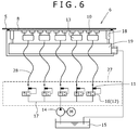
- This tire traveling test device 1 of the third embodiment differs from that of the first embodiment in a point that a flow rate adjustment means 27 which adjusts a flow rate of the support liquid discharged from the plural liquid supply holes 10 is provided separately from a load support device 6 with being spaced from the load support device 6.
- the support liquid supply chamber 13 or the support liquid recycle unit 19 was disposed immediately below the upper face (the tire support face 8) of the above described load support device 6 which support the belt 5, and the members such as the switch valve 16, the pump 14, or the storage tank 15 (the flow rate adjustment means 27) were disposed further below the support liquid supply chamber 13 or the support liquid recycle unit 19. That is, the flow rate adjustment means 27 of the first embodiment described above had a structure in which both the flow rate adjustment means 27 and the load support device 6 are present inside the load support device 6.
- the switch valve 16, a pump 14, and a storage tank 15 which constitute the flow rate adjustment means 27 are provided in a separate position spaced from the load support device 6. That is, the load support device 6 and the flow rate adjustment means 27 are disposed separately from each other and these members are connected with each other via a water introduction tube 28.
- the surface of the tire support face 8 of the third embodiment is provided with the liquid supply holes 10
- the surface of this tire support face 8 is not provided with such a pressure sensor 11 as provided in the first embodiment.
- Such pressure sensor 11 is provided in the tip of the water introduction tube 28 which is disposed on the support liquid supply chamber 13 linked to the lower ends of the liquid supply holes 10 (the water introduction tube 28 in the side nearest to the flow rate adjustment means 27).
- This water introduction tube 28 is formed, for example, with a tube material bendable freely as a flexible tube, and is capable of linking between the flow rate adjustment means 27 and the load support device 6 disposed at a distance, in various route. Use of such freely bendable water introduction tube 28 allows the flow rate adjustment means 27 to be provided without influence of a layout in a factory or the like where the device is installed, and thus, it becomes possible to improve convenience of the tire traveling test device 1.
- the water introduction tube 28 is provided with the pressure sensor 11, in the end part in the side of the flow rate adjustment means 27.
- the pressure sensor 11 is configured to be capable of measuring a pressure of the tire support face 8, at the end part of the water introduction tube 28, positioned in the side opposite to the liquid supply hole 10.
- the pressure sensor 11 is disposed in each of the plural water introduction tubes 28, and is capable of measuring pressure in each of the water introduction tubes 28. A pressure of the support liquid measured by this pressure sensor 11 is sent as a measured signal to the switch valve 16 (the flow rate adjustment valve 12) as a "pressure on the tire support face 8".
- the switch valve 16 is configured to open/close the circulation of the support liquid in each of the water introduction tubes 28 described above, such that the "pressure on the tire support face 8" measured by the pressure sensor 11 becomes equal to or higher than the predetermined set value for pressure, similarly as in the first embodiment.
- the switch valve 16 (the flow rate adjustment valve 12) is switched to "OPEN (ON)". Accordingly, the support liquid in the storage tank 15 is introduced to the support liquid supply chamber 13 through a support liquid supply tube 17 and the water introduction tubes 28 by the pump 14 described above, and then, the support liquid in the support liquid supply chamber 13 is blown out from the tire support face 8 through the liquid supply holes 10, to thereby float the belt 5 with a static pressure of the support liquid blown out between the belt 5 and the load support device 6 which are water-tightly isolated by a water-sealing seal.
- the flow rate adjustment valve 12 is switched to "CLOSE (OFF)". Accordingly, the support liquid in the storage tank 15 described above is stopped being introduced to the support liquid supply chamber 13 through the support liquid supply tube 17 and the water introduction tubes 28, and the support liquid in the support liquid supply chamber 13 stops being blown out from the liquid supply holes 10. As a result, the support liquid stops being blown out wastefully from the liquid supply holes 10 which are positioned in a region where a tire is not in ground contact, and a wasteful use of the support liquid is suppressed.
- the traveling test device 1 of the third embodiment since the flow rate adjustment means 27 provided separately from the load support device 6 has an extremely simple structure, it becomes easy to check the valve operation status in the flow rate adjustment means 27. For example, the valve operation will be further easily checked, by making a part of the flow rate adjustment means 27 with glass or acrylic glass to visualize the inside, or by providing each of the water introduction tubes with a flow rate meter, and thus, it is also possible to contribute to an improvement in maintainability.
- the load support device 6 has a complex structure comprising orifices, etc., and is difficult to be disassembled in many cases.
- the traveling test device 1 of the third embodiment it is not necessary to coincide a position of the switch valve 16 of the flow rate adjustment means 27 with a position of the liquid supply hole 10 of the load support device 6 in the horizontal direction, and therefore, it becomes possible to adopt a free layout which is easy in maintenance or in designing to the flow rate adjustment means 27.
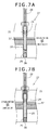
- the tire traveling test device 1 of the fourth embodiment is also configured to use a piston 20 (a piston valve which is operated passively) which moves in the up-down direction inside a through hole 21, similarly as in the second embodiment.
- the tire traveling test device 1 of the fourth embodiment differs from that of the second embodiment in a point that a load support device 6 and a flow rate adjustment means 27 are separately provided and the two members are connected with each other via a water introduction tube 28, similarly as in the third embodiment.
- the flow rate adjustment means 27 of the fourth embodiment comprises the piston 20 in a movable manner in the up-down direction inside the through hole 21 which is formed along the up-down direction, as in the second embodiment.
- This piston 20 also functions as a piston valve.
- the lower end of this piston 20 is provided with a spring 25 which urges the piston 20 to be pushed upward along the direction in which the through hole 21 is formed.
- the upper end of the through hole 21 opens upward, and the above described water introduction tube 28 is linked to this opening of the through hole 21.
- the piston 20 of the fourth embodiment also is provided with a cut out 24 having a small outer diameter compared to the side of upper end or the side of lower end, in middle side of the up-down direction. That is, although there is little gap formed between the inner circumferential face of the through hole 21 and the outer circumferential face of the piston 20 in the side of upper end or the side of lower end of the piston 20, a gap is formed in the radial direction between the inner circumferential face of the through hole 21 and the outer circumferential face of the piston 20 (cut out 24) in the middle side of the piston 20 where the cut out 24 is formed, and through this gap, the support liquid is allowed to circulate in the up-down direction.
- the tire traveling test device 1 of the fourth embodiment it is possible, also according to the tire traveling test device 1 of the fourth embodiment, to obtain an effect of inhibiting the support liquid from being wastefully blown out from a liquid supply hole 10 (circular hole) in a region where a tire is not in ground contact, while the device is capable of floating a tire up to a sufficient height relative to the upper face of the load support device 6.
- a pressure of the support liquid on the tire support face 8 was introduced to the pressure sensor 11 or the piston 20 of the flow rate adjustment means 27 through the water introduction tube 28.
- this water introduction tube 28 is to circulate the support liquid in the side of the tire support face 8 as needed, and due to the support liquid flowing at a predetermined flow velocity, considerable pressure loss occurs in the water introduction tube 28.
- the pressure of the support liquid on the tire support face 8 is introduced to a flow rate adjustment means 27 not by a water introduction tube 28 but by a pressure introduction tube 29.
- a pressure detection hole 31 which detects a pressure of the support liquid on the tire support face 8 is formed on the surface of the tire support face 8.
- the aforementioned pressure introduction tube 29 is configured to have a structure with a side of one end opened to this pressure detection hole 31, and a side of the other end opened to the side of the pressure sensor 11 of the flow rate adjustment means 27.
- the support liquid does not circulate as in the above described water introduction tube 28, and therefore, it is possible that a pressure on the tire support face 8 (the pressure detection hole 31) of the load support device 6 is transmitted to the pressure sensor 11 of the flow rate adjustment means 27 provided separately from this load support device 6, without generating the pressure loss.
- a pressure on the tire support face 8 (the pressure detection hole 31) of the load support device 6 is transmitted to the pressure sensor 11 of the flow rate adjustment means 27 provided separately from this load support device 6, without generating the pressure loss.
- the pressure of the support liquid on the tire support face 8 is introduced to the flow rate adjustment means 27 not by the water introduction tube 28 but by the pressure introduction tube 29, similarly as in the fifth embodiment.
- a branch tube 30 which extends along the upward direction as a through hole 21 is formed inside the flow rate adjustment means 27.
- This branch tube 30 is formed in a side of the through hole 21, and the lower end of the branch tube 30 is connected to the middle side in the up-down direction of the through hole 21.
- the lower end of the water introduction tube 28 is linked to the upper end of this branch tube 30 .
- the upper end of the pressure introduction tube 29 is connected to the pressure detection hole 31 described above.
- an upper end of the through hole 21 opens upward, and to this opening of the through hole 21, the aforementioned pressure introduction tube 29 is linked.
- the traveling test device 1 of the sixth embodiment has a structure in which a pressure on the tire support face 8 directly effects the piston 20 without the pressure loss, the opening/closing operation (up-down motion) of the piston 20 is stabilized, and it becomes possible to surely perform the flow rate adjustment of the support liquid by the flow rate adjustment means 27.
- the second embodiment described above was provided with a mechanism to assist the closing of the piston 20, in which the lower side of the piston 20 is provided with the spring 25 which urges the piston 20 upward such that the force required in closing valve becomes small compared to the force required in valve opening motion.
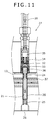
- the outside of piston 20 is provided with a valve member 32 which moves in the up-down direction with being caught in the outer circumferential face of this piston 20. That is, the flow rate adjustment means 27 of the seventh embodiment is provided with the valve member 32 which avoids the "kept opened state" of the piston 20, in addition to the piston 20 which adjust the flow rate of the support liquid.
- this valve member 32 is a cylindrical member engageable with the upper side of the piston 20 from a cut out 24 with a play outside, and is inserted inside a through hole 21 in a manner movable in the up-down direction.
- This valve member 32 comprises an inside-outside circulation opening 33 which penetrates the outer circumferential wall through the inside and outside thereof along the radial direction.
- the inside-outside circulation openings 33 are formed on the circumferential wall of the valve member 32 over plural points (for example, three points or four points) with substantially equal spaces in the circumferential direction, and configured to be capable of introducing the support liquid in the outside of the valve member 32 into the inside through the circumferential wall.
- the upper side of the valve member 32 is provided with a second spring 34 which urges this valve member 32 downward.
- the upper end of this second spring 34 is attached to a support piece 35 formed inside the through hole 21 in a fixed manner.
- This support piece 35 provided inside the through hole 21 is fixed in the center side of the through hole 21 with a support member or the like which is not illustrated.
- the lower end of the second spring 34 is attached to the valve member 32 such that the second spring 34 is capable of urging the valve member 32 downward relative to the support piece 35.
- the through hole 21 provided to the flow rate adjustment means 27 of the seventh embodiment is configured to have a cylindrical shape such that the inner diameter is larger in the upper side than in the lower side, and the cylindrical part in the upper side with this larger inner diameter is capable of being inserted with the valve member 32 inside. Furthermore, on the inner circumferential face of the through hole 21, a support liquid guide member 36 which guides the support liquid in the support liquid supply chamber 13 along the up-down direction is formed, and thus, the support liquid is allowed to be circulated in the up-down direction with the support liquid guide member 36 even in a state that the valve member 32 is inserted inside.
- This support liquid guide member 36 is formed on positions corresponding to the positions in the circumferential direction on which the inside-outside circulation openings 33 are formed, and configured to be capable of guiding the support liquid of the support liquid supply chamber 13 upward and then introducing it into the inside-outside circulation opening 33.
- the "kept opened state" of the piston 20 is controlled by the valve member 32 operated as shown below.
- a pressure of the support liquid on the tire support face 8 via the water introduction tube 28 has become high and the piston 20 is in the OPEN state.
- the pressure of the support liquid affecting the upper face of the piston 20 is exceeding a predetermined pressure, and accordingly, the piston 20 moves downward against the force of the spring 25.
- the support liquid of the water supply path 37 flows into the support liquid supply chamber 13.
- the support liquid which has flowed into the support liquid supply chamber 13 in this manner moves through the plural support liquid guide members 36 and through the inside-outside circulation openings 33 described above, further to the inside of the through hole 21 above the piston 20.
- the support liquid inside the through hole 21 above the piston 20 is supplied to the tire support face 8 through the water introduction tube 28, to increase the pressure of the support liquid on the tire support face 8 to thereby allow a tire to be floated up to a sufficient height.
- the support liquid guide member 36 described above is a narrow path (a path difficult to pass through for being narrow) compared to the gap of the cut out 24 or the inside-outside circulation opening 33, which is formed to be the narrowest among the paths through which the support liquid circulates. Therefore, when the support liquid is introduced to such a narrow path, a large pressure loss is generated, and due to the generated pressure loss, a force is applied to the valve member 32 upward.
- valve member 32 moves upward against the urging force of the second spring 34.
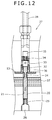
- the valve member 32 moves upward up to the position shown in Fig. 12 , the position of the opening of the support liquid guide member 36 and the position of the opening of the inside-outside circulation opening 33 is shifted in the up-down direction to thereby shut off the communication between the support liquid guide member 36 and the inside-outside circulation opening 33 and the supply of the support liquid is stopped.
- this valve member 32 is configured to have a structure which controls the "kept opened status" of the piston 20 by shutting the supply of the support liquid only when the force of the support liquid circulating through the support liquid guide member 36 is large.
- the present invention is based on the Japanese patent application No. JP 2013-117089 filed on June 3, 2013 , the content of which is herein incorporated by reference.
Landscapes
- Physics & Mathematics (AREA)
- General Physics & Mathematics (AREA)
- Tires In General (AREA)
Abstract
Description
- The present invention relates to a tire traveling test device.
- Conventionally, as a tire traveling test device which evaluates traveling property of tires, those using an endless flat belt (herebelow referred to as belt) which imitates a flat road surface have been known. In such traveling test devices, a belt is spanned over two drums. Specifically, the belt mentioned above is spanned over two drums in a manner separated into upper side and lower side, the upper side belt constituting a ground contact face for tire which allows a tire a ground contact. On the other hand, the belt, in the back side of this ground contact face for tire, is provided with a load support device which prevents the belt from bending, and supports a tire load.
- The load support device is configured to have a structure in which a support liquid, such as a pressurized water or oil, is supplied between the upper face (belt supporting face) of this load support device and the lower face of the belt, in order to smoothly support running of the belt. That is, the load support device comprises a function to support the belt by supplying the support liquid to the contacting face of the belt to thereby float the belt.
- As a traveling test device which adopt the technique of floating a belt from a load support device by use of a pressurized support liquid in this way, those disclosed in the
Patent Document 1 andPatent Document 2 have been known. - These traveling test devices of the
Patent Document 1 and thePatent Document 2 both have a structure which supplies the support liquid by providing plural circular holes on the upper face of the load support device, and blowing out the pressurized support liquid from these plural circular holes. In a case of adopting such method of supplying a support liquid, the circular holes will be closed in those regions where a tire is in ground contact, to suppress the amount of the support liquid to be blown out according to a ground contacting pressure, in the upper face of the load support device. However, the support liquid easily leaks out from the circular holes disposed in a region where a tire is not in ground contact, or in a region where a ground contact pressure of the tire is low. This causes, further enhanced by a force of the support liquid blown out from the circular holes, the belt to be further floated from the upper face of the load support device, and the floating of the belt becomes further excessive to require a significant amount of support liquid to be continuously supplied, which brings about a lowering of supplying pressure of the support liquid, or causes an increase of energy loss. - In order to lower such energy loss, in the traveling test device of the
Patent Document 1, plural chambers are constructed in a liquid pressure receiving unit of the belt so as to be able to supply the each chamber with support liquid each different in liquid pressure. In such a structure, it is possible to control a liquid pressure of the support liquid to be high in a part where a tire is in ground contact, and to control a liquid pressure of the support liquid to be low in a part where a tire is not in ground contact, and accordingly, it becomes possible to avoid a wasteful use of the support liquid and control the energy loss to be small. - The traveling test device of the
Patent Document 2 is provided with an orifice between circular holes which blow out a pressurized support liquid and a supply unit which supplies these circular holes with a high pressure support liquid. By providing such an orifice, a wasteful blowing out of the support liquid from the circular holes is controlled by a pressure loss at the time of passing through the orifice, to inhibit the wasteful use of the support liquid, and as a result, it becomes possible to lower the energy loss. -
- Patent Document 1: Japanese utility model application laid-open No.
H04-109349 - Patent Document 2: Japanese patent application laid-open No.
H11-173953 - Incidentally, on the upper face of the belt, the region where a tire is in ground contact varies in position or in area, depending on test loads or test conditions such as fitting alignments of a tire (for example, a condition such as slip angle or camber angle). Accordingly, in the method of the
Patent Document 1, it is necessary that the liquid pressure receiving unit of the belt is divided into parts as small as possible so as to be capable of responding to cases that a ground contact region of a tire is changed, and to minutely varying flow rate etc. of the support liquid individually in the divided portions, which makes the test method extremely complicated. Furthermore, in this method of thePatent Document 1, it is also necessary to distinguish a part where a tire is in ground contact from a part where a tire is not in ground contact, which tends to make the device structure of the testing device complicated. - In the method of the
Patent Document 2, in order to inhibit the support liquid from blowing out from the circular holes in a region where a tire is not in ground contact, it is necessary to make the diameter of the orifice as small as possible. However, if such an orifice with a small diameter is used, the flow rate of the support liquid blown out from circular holes in a part where a tire is in ground contact is also limited, to make the floating amount of the belt small. Therefore, if a flexible material is used in the belt, the belt will bend and easily cause a problem such that the bent belt contacts a load support device. - The present invention has been accomplished in view of the above described problems, and aims to provide a tire traveling test device which is capable of inhibiting a support liquid from being wastefully blown out from circular holes in a region where a tire is not in ground contact, while being capable of floating a belt up to a sufficient height relative to the upper face of a load support device.
- In order to achieve the above objects, the present invention takes the following technical measures.
- That is, the tire traveling test device of the present invention is characterized in that, in a tire traveling test device comprising a belt horizontally spanned between two drums and a load support device which supports flat face of the belt from the side of lower face, the load support device is provided with a liquid supply means which supplies a support liquid between the load support device and the belt to support the belt from below; the liquid supply means comprising liquid supply holes, capable of discharging the support liquid between the load support device and the belt, in plural numbers along the upper face of the load support device, and flow rate of the support liquid discharged from each of the liquid supply holes being adjustable on the basis of a fluid pressure on the upper face of the load support device which varies according to a ground contact state of the tire.
- Incidentally, it is preferred that the liquid supply means is provided along the upper face of the load support device in plural numbers, and comprises a pressure sensor which measures a fluid pressure on the upper face of the load support device.
- Incidentally, it is preferred that the liquid supply means comprises a flow rate adjustment valve capable of adjusting a flow rate of the support liquid discharged from each of the liquid supply holes by adjusting a valve opening degree on the basis of a fluid pressure on the upper face of the load support device.
- Incidentally, it is preferred that the flow rate adjustment valve is configured to have a structure in which a force required in a valve closing becomes small compared to a force required in a valve opening motion.
- Incidentally, it is preferred that the liquid supply means is configured to have a structure which adjusts the flow rate of the support liquid discharged from each of the liquid supply holes such that a supplying pressure of the support liquid discharged from each of the liquid supply holes becomes larger than an internal pressure of a tire.
- Incidentally, it is preferred that a flow rate adjustment means which adjusts a flow rate of the support liquid discharged from each of the liquid supply holes is provided separately from the load support device, and that the plural liquid supply holes provided on the load support device and the flow rate adjustment means which adjusts the flow rate of the support liquid discharged from the plural liquid supply holes are linked with each other with plural water introduction tubes.
- Incidentally, it is preferred that the flow rate adjustment means comprises a sensor provided separately from the load support device, which is capable of measuring a pressure or a flow rate of the support liquid on the upper face of the load support device, and that the flow rate of the support liquid passing through the water introduction tubes are adjusted on the basis of a measured signal of the pressure or the flow rate measured by the sensor.
- Incidentally, it is preferred that the flow rate adjustment means comprises a flow rate adjustment valve which is capable of adjusting a flow rate of the support liquid discharged from each of the liquid supply holes by adjusting a valve opening degree on the basis of a pressure or a flow rate of the support liquid circulating through the water introduction tubes.
- According to the tire traveling test device of the present invention, it is possible to inhibit the support liquid from being wastefully blown out from the circular holes in a region where a tire is not in ground contact, while the device is capable of floating a tire up to a sufficient height relative to the upper face of the load support device.
-
- [
Fig. 1] Fig. 1 is a front view of a tire traveling test device of the present invention. - [
Fig. 2] Fig. 2 is a plan view showing an arrangement of circular holes on the upper face of a load support device. - [
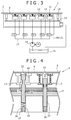
Fig. 3] Fig. 3 is a structural view of liquid supply units, including a sectional view of the same taken along the line III-III ofFig. 2 . - [
Fig. 4] Fig. 4 is a sectional view of flow rate adjustment valves. - [
Fig. 5] Fig. 5 is an enlarged view of a liquid supply unit of a second embodiment. - [
Fig. 6] Fig. 6 is a structural view showing liquid supply units of a third embodiment. - [
Fig.7A] Fig. 7A is a partially enlarged view showing a structure and a movement of a liquid supply unit of a fourth embodiment. - [
Fig. 7B] Fig. 7B is a partially enlarged view showing a structure and a movement of the liquid supply unit of the fourth embodiment. - [
Fig. 8] Fig. 8 is a structural view showing liquid supply units of a fifth embodiment. - [
Fig.9A] Fig. 9A is a partially enlarged view showing a structure and a movement of a liquid supply unit of a sixth embodiment. - [
Fig. 9B] Fig. 9B is a partially enlarged view showing a structure and a movement of the liquid supply unit of the sixth embodiment. - [
Fig. 10] Fig. 10 is a partially enlarged view showing a structure and a movement of a liquid supply unit of a seventh embodiment. - [
Fig. 11] Fig. 11 is a partially enlarged view showing a structure and a movement of the liquid supply unit of the seventh embodiment. - [
Fig. 12] Fig. 12 is a partially enlarged view showing a structure and a movement of the liquid supply unit of the seventh embodiment. - [
Fig. 13] Fig. 13 is a partially enlarged view showing a structure and a movement of the liquid supply unit of the seventh embodiment. - Hereinbelow, a tire traveling
test device 1 according to the present invention will be described in detail on the basis of the drawings. - As shown in
Fig. 1 , the tire travelingtest device 1 comprises aspindle axis 2 to mount a tire, a drivingdrum 3 configured to be rotatable forward and backward, a drivendrum 4 provided with being spaced from the drivingdrum 3 in such a manner that the center axes thereof are parallel with each other, and a traveling belt (hereinafter referred to as belt 5) which is an endless metal plate spanned between the drivingdrum 3 and the drivendrum 4. - Between these driving
drum 3 and drivendrum 4, thebelt 5 is spanned with its upper and lower sections extending in parallel to each other. The upper and lower sections of thebelt 5, the upper and lower sections being in parallel to each other, are disposed such that they are both directed in a horizontal direction. By contacting a tire with a flat road surface (a test road surface) formed on the upper face of the upper section of thebelt 5, it is possible to evaluate a traveling property of the tire which rolls on a road surface. On the other hand, the back face of the road surface (the lower face of thebelt 5 corresponding to the test road surface) is provided with aload support device 6 which supports thebelt 5 which bears a tire load. - The
load support device 6 is a member the upper face thereof being flat so as to support thebelt 5 from below, which is configured to support thebelt 5 from below with contacting the upper face with the lower face of thebelt 5. The upper face of the tireload support device 6 is provided with a liquid supply means 7 which ejects a pressurized support liquid between theload support device 6 and thebelt 5. - Specifically, the
load support device 6 is configured such that the upper face thereof constitutes atire support face 8 which supports a tire, and thebelt 5 can be slid along thistire support face 8. In thistire support face 8, a length along a direction perpendicular to the belt running direction (hereinafter, the width direction) is slightly larger than the width of thebelt 5, and thebelt 5 can be supported throughout the whole area in the width direction thereof. Furthermore, thetire support face 8 is provided with the liquid supply means 7 which ejects a support liquid such as a pressurized water, oil, or the like onto the back face of thebelt 5. By using a static pressure of the support liquid supplied from this liquid supply means 7, theload support device 6 floats thebelt 5 from the upper face of the load support device 6 (the tire support face 8) so as not to contact thebelt 5 with thetire support face 8. - As shown in
Fig. 2 andFig. 3 , the liquid supply means 7 is to supply the support liquid to thetire support face 8 and to float thebelt 5 by using a static pressure of the supplied support liquid. The liquid supply means 7 comprises members such as pluralliquid supply units 9 provided along thetire support face 8, astorage tank 15 which stores the support liquid, a flowrate adjustment valve 12, aswitch valve 16, a supportliquid supply tube 17, etc. - Specifically, the plural
liquid supply units 9 each comprise a liquid supply hole 10 (a circular hole) which discharges the support liquid and apressure sensor 11 which measures a pressure of the support liquid (fluid pressure) on thetire support face 8, and are disposed at equal intervals on thetire support face 8, in such a manner to be arranged in rows in the traveling direction of the tire and in the width direction with predetermined spaces. - Each of the above described
liquid supply units 9 has thepressure sensor 11 provided in plural numbers at equal intervals along thetire support face 8. One or more liquid supply holes described above are provided so as to correspond to theseindividual pressure sensors 11, and thus, oneliquid supply unit 9 is comprised of these liquid supply holes 10 and thepressure sensor 11. Theliquid supply unit 9 also comprises the flowrate adjustment valve 12 which allows an adjustment of a valve opening degree based on a fluid pressure measured by thispressure sensor 11, constituting a structure in which the flowrate adjustment valve 12 adjusts flow rates of the support liquid discharged from theliquid supply hole 10 of each of theliquid supply unit 9. - The
liquid supply unit 9 of the present embodiment comprises thepressure sensor 11 disposed in the center, and four liquid supply holes 10 disposed having thispressure sensor 11 as a center in common. Incidentally, number of theliquid supply hole 10 which constitutes theliquid supply unit 9 is not limited to four. For example, it is also possible to use aliquid supply unit 9 provided with each onepressure sensor 11 andliquid supply hole 10, or aliquid supply unit 9 provided with two, three, five, or more liquid supply holes 10 to onepressure sensor 11. - The above described
liquid supply hole 10 is a hole formed on thetire support face 8, directed to an up-down direction, forming a structure which blows out the support liquid supplied from below onto thetire support face 8 to thereby float thebelt 5 by use of a static pressure of the support liquid blown out. Specifically, the lower end of theliquid supply hole 10 is provided with a supportliquid supply chamber 13 which stores the support liquid, constituting a structure in which the support liquid stored in this supportliquid supply chamber 13 is distributed and sent to each of the four liquid supply holes 10 at each of theliquid supply units 9. - As shown by broken lines in
Fig. 2 , the supportliquid supply chamber 13 is a cylindrical space formed inside theload support device 6, configured to be capable of storing the support liquid inside. The upper side of this supportliquid supply chamber 13 is connected to the above describedliquid supply hole 10 in a manner communicated therewith. - The upper side of the
liquid supply hole 10 is formed into a cylindrical shape having a diameter larger than that of the lower side which communicates with the supportliquid supply chamber 13, so that the support liquid has a larger contact area with thebelt 5 and exert a sufficient floating power to thebelt 5. - Furthermore, a supplying pressure of the support liquid supplied from the
liquid supply hole 10 is controlled to be larger than an internal pressure of a tire, by adjusting a flow rate of the support liquid discharged by using apump 14 which will be described later, the flowrate adjustment valve 12, or the like. Purpose of making a supplying pressure of the support liquid larger than an internal pressure of a tire in this way is to sufficiently float a tire which has a hardness of a gum in addition to the air pressure. - That is, provided that a hardness of a gum of a tire is zero, a ground contact pressure of the tire coincides with the internal pressure of the tire. However, since an actual tire has a hardness of a gum, a tire has a ground contact pressure larger in value than an internal pressure of the tire in proportion to the gum hardness of the tire.
- Meanwhile, a state where the
belt 5 floats from thetire support face 8 is a state where a pressure in the gap between theload support device 6 and thebelt 5 is approximately equal to a ground contact pressure of the tire. In order to blow out the support liquid into this gap, a pressure at least larger than the internal pressure of the tire is required as the supplying pressure of the support liquid. - From these reasons, in trying to float the
belt 5 from the upper face of theload support device 6, with keeping a tire loaded thereon, the supplying pressure of the support liquid should be made to be a value larger than an internal pressure of the tire. - The pressure sensor 11 (a pressure detection unit) is provided in the center of the
liquid supply unit 9 described above, to measure a pressure of the support liquid disposed between thetire support face 8 and thebelt 5. In theliquid supply unit 9, flow rates of the support liquid to be supplied from the four liquid supply holes 10 disposed in thisliquid supply unit 9 are collectively adjusted on the basis of the pressures measured by thepressure sensor 11. - Concretely, the
pressure sensor 11 is attached to the upper face of theload support device 6, and formed with a pressure-sensitive element or the like which measures the pressure of the support liquid. A pressure of the support liquid measured by thispressure sensor 11 is sent as a measured signal to the flowrate adjustment valve 12. - The flow
rate adjustment valve 12 adjusts a flow rate of the support liquid supplied from theliquid supply hole 10 disposed in theliquid supply unit 9. This flowrate adjustment valve 12 is provided to the supportliquid supply tube 17 which supplies the support liquid to the supportliquid supply chamber 13 provided to each of theliquid supply units 9 from thestorage tank 15 which will be described later, and comprises theswitch valve 16 capable of opening/closing the valve on the basis of the measured signal input from thepressure sensor 11. Concretely, the flowrate adjustment valve 12 has a set value for pressure input in advance, and adjusts a valve opening degree by comparing the set value for pressure with a value measured by thepressure sensor 11. - Used as this set value for pressure is a pressure value by which it is possible to distinguish whether or not a tire is in ground contact. For example, by using a value larger than an atmospheric pressure and not exceeding an internal pressure of a tire as the set value for pressure, it will be possible to distinguish whether or not the tire is in ground contact or not. For example, since the internal pressure of a tire generally is about 2 atmospheres (203 × 103 Pa) (gauge pressure) in a passenger car, and more in a truck and bus, it is preferred that the aforementioned set value for pressure is set to about 1 atmosphere (101 × 103 Pa) (gauge pressure).
- The lower end of the above described support
liquid supply tube 17 is provided with thestorage tank 15 which stores a used support liquid which was used in a tire traveling test, and thepump 14 which sends the support liquid stored in thisstorage tank 15 to the flowrate adjustment valve 12 of each of theliquid supply units 9 via the supportliquid supply tube 17. - Furthermore, the upper face of the
load support device 6 is provided with awater recovering groove 18 which collects the support liquid supplied from the liquid supply holes 10. Thiswater recovering groove 18 is formed in a manner to surround theliquid supply unit 9 from around on the upper face of theload support device 6, so as to be capable of collecting the support liquid blown out from each of the liquid supply holes 10, in the outer side of theliquid supply unit 9. - The lower side of the
water recovering groove 18 is provided with a supportliquid recycle unit 19 which temporary recycles the support liquid collected by thiswater recovering groove 18. This supportliquid recycle unit 19 is a chamber (a room) which is formed inside theload support device 6 in an isolated state with a water-sealing seal, constituting a structure in which the support liquid collected by thewater recovering groove 18 is collectively returned to the above describedstorage tank 15. That is, the liquid supply means 7 of the present embodiment has a structure in which a recycle use of the support liquid is available in such a manner that the support liquid blown out on thetire support face 8 from the liquid supply holes 10 is collected and returned to thestorage tank 15 and reused in the blowing out from the liquid supply holes 10. - In the next place, a method of floating the
belt 5 by use of the liquid supply means 7 described above, in other words, the tire traveling test method of the present invention will be described. - For example, provided here is a case where a pressure of a support liquid is measured by the
pressure sensor 11 of aliquid supply unit 9, and the measured value of the pressure measured by thepressure sensor 11 is larger than a set value for pressure input in advance. - Here, the set value for pressure is a value larger than an atmospheric pressure and smaller than an internal pressure of a tire, as described above. In other words, this set value for pressure is set to be a value by which it is distinguishable whether or not a measured value of the pressure is larger than an internal pressure of a tire. Thus, when the measured value of the pressure is larger than the set value, it is considered that a pressure larger than an atmospheric pressure is applied between the
belt 5 and thetire support face 8, and accordingly, it can be judged that "the tire is in ground contact". - In such cases, the flow
rate adjustment valve 12 is switched to "OPEN (ON)". Then, the support liquid in thestorage tank 15 is introduced to the supportliquid supply chamber 13 through the supportliquid supply tube 17 by thepump 14 described above, and further, the support liquid in the supportliquid supply chamber 13 is blown out from thetire support face 8 through the liquid supply holes 10 to thereby float thebelt 5 with a static pressure of the blown out support liquid. - On the other hand, when the measured value of the pressure measured by the
pressure sensor 11 is smaller than a set value for pressure input in advance, in other words, when the pressure generated between thebelt 5 and thetire support face 8 is in a degree similar to an atmospheric pressure, it can be judged that "the tire is not in ground contact". - In such cases, the flow
rate adjustment valve 12 is switched to "CLOSE (OFF)". Accordingly, the support liquid in thestorage tank 15 described above stops being introduced to the supportliquid supply chamber 13 through the supportliquid supply tube 17, and then, the support liquid in the supportliquid supply chamber 13 stops being blown out from the liquid supply holes 10. As a result, the support liquid stops being blown out wastefully from liquid supply holes 10 which are positioned in a region where a tire is not in ground contact, and a wasteful use of the support liquid is suppressed. - By use of the above described liquid supply means 7, the support liquid is blown out from the liquid supply holes 10 in a region where a tire is in ground contact, to allow the
belt 5 to float up to a sufficient height relative to the upper face of theload support device 6. On the other hand, in a region where a tire is not in ground contact, the support liquid is stopped being blown out from the liquid supply holes 10, and thus, it becomes possible to suppress a wasteful blowing out of the support liquid to minimize an energy loss. - In the next place, a tire traveling
test device 1 of a second embodiment will be described with using drawings. - As shown in
Fig. 4 , the tire travelingtest device 1 of the second embodiment does not comprise thepressure sensor 11 or the flowrate adjustment valve 12 differently from that of the first embodiment, and is configured to have a structure in which apiston 20 which detects a pressure of the support liquid and performs a valve operation is directly incorporated inside aload support device 6. In other words, the tire travelingtest device 1 of the second embodiment is a device which uses a piston-valve having both function of detecting a pressure and function of adjusting a flow rate of the support liquid. - Concretely, the traveling
test device 1 of the second embodiment comprises a throughhole 21 which penetrates the inside of theload support device 6 in an up-down direction. This throughhole 21 penetrates awater supply path 37 formed inside theload support device 6 in the up-down direction from below thewater supply path 37, and extends upward from thewater supply path 37, and further penetrates a supportliquid supply chamber 13 provided above thewater supply path 37, and extends further upward from the supportliquid supply chamber 13. The upper end of this throughhole 21 opens on the upper face of theload support device 6. Inside this throughhole 21, theaforementioned piston 20 is accommodated in a manner movable in the up-down direction. - The upper end and the lower end of the through
hole 21 are narrowed compared to the middle side in the up-down direction, so that the inner diameter of the throughhole 21 is configured to be a smaller diameter than in the middle side. That is, the upper end and the lower end of the throughhole 21 are processed to reduce the diameter such that the inner diameter is within a size capable of being engaged with the outer periphery of thepiston 20, so as to be capable of controlling up-down movement of thepiston 20. Specifically, the upper end of the throughhole 21 is configured as an upperside position fixer 22 which controls this upper limit position. The lower end of the throughhole 21 is configured as aspring fixing part 23 that fixes aspring 25 which will be described later. The lower end is further provided with astopper 26 which performs a position fixing in the lower side of the piston. - The
piston 20 is a cylindrical member having a diameter (an outer diameter) slightly smaller than the inner diameter of the throughhole 21, configured to be movable inside the throughhole 21 in the up-down direction. The middle side in the up-down direction of thepiston 20 is made as a cut out 24 having a small diameter compared to that in the side of upper end or the side of lower end. That is, in the side of upper end or the side of lower end of thepiston 20, there is little gap formed between the inner circumferential face of the throughhole 21 and the outer circumferential face of thepiston 20. However, in the middle side of thepiston 20 where the cut out 24 is formed, a gap is formed in the radial direction between the inner circumferential face of the throughhole 21 and the outer circumferential face of the piston 20 (the cut out 24), so that the support liquid is allowed to circulate in the up-down direction through this gap. Therefore, if thepiston 20 is moved to such a position that the cut out 24 spans over both thewater supply path 37 and the supportliquid supply chamber 13 by moving thepiston 20 in the up-down direction along the throughhole 21 described above, it becomes possible to move the support liquid in thewater supply path 37 to the supportliquid supply chamber 13 by use of the cut out 24. - The upper face of the
piston 20 described above is formed into a flat face along the horizontal direction. This upper face of thepiston 20 is applied with a pressure of the support liquid which is supplied between the upper face of theload support device 6 and the lower face of thebelt 5, such that thepiston 20 can be pushed downward. - The lower face of the
piston 20 is formed into a flat face along the horizontal direction as the upper face of thepiston 20 is. The lower face of thepiston 20 is affected by an atmospheric pressure. Thespring 25 is disposed on this lower face of thepiston 20, and an urging force of thisspring 25 is applied to the lower face of thepiston 20, such that thepiston 20 can be pushed upward. A gap pressure for the piston to operate is adjusted by adjusting this spring force. - In the next place, a method of floating the
belt 5 by use of the liquid supply means 7 of the second embodiment described above, in other words, the tire traveling test method of the second embodiment will be described. - For example, provided here is a case where a pressure larger than the above described set value for pressure affects the upper face of the above described
piston 20, in other words, a case where "a tire is in ground contact". - In such cases, a pressure in the gap between the
belt 5 and thetire support face 8 is increased due to the ground contact of the tire, and a pressure applied to the upper face of thepiston 20 from above is also increased. When this force applied topiston 20 exceeds the urging force of thespring 25 described above, thepiston 20 moves downward until it touches thestopper 26, and the liquid supply means 7 is switched to "OPEN (ON)". - Then, as shown in the right side of
Fig. 4 , thepiston 20 moves to the lower end of the throughhole 21. When thepiston 20 comes to slightly above thespring fixing part 23, thewater supply path 37 and the supportliquid supply chamber 13 are brought into a communicating state through the cut out 24, and the support liquid in thewater supply path 37 is sent to the supportliquid supply chamber 13 through the cut out 24. As a result, the support liquid in the supportliquid supply chamber 13 is blown out from theliquid supply hole 10, and thebelt 5 is floated with a static pressure of the blown out support liquid. - Next, provided here is a case where a pressure smaller than the above described set value for pressure affects the upper end of the above described
piston 20, in other words, a case where "a tire is not in ground contact" or a case where "a ground contact pressure from a tire is decreased" due to a change in tire alignment or a decrease in load. - When the pressure applied from a tire is decreased in this way, the pressure in the gap between the
belt 5 and thetire support face 8 is decreased, and the power applied from above to the upper face of thepiston 20 is also decreased. Then, the urging force of thespring 25 described above exceeds the force applied from above to thepiston 20, then, thepiston 20 is moved upward with the urging force of thespring 25, and the liquid supply means 7 is switched from "OPEN (ON)" to "CLOSE (OFF)". - Accordingly, as shown in the left side of
Fig. 4 , thepiston 20 moves to the upper end of the throughhole 21, and when thepiston 20 comes to the position of theposition fixer 22 in the upper side, thewater supply path 37 and the supportliquid supply chamber 13 are brought into non-communicating state, and the support liquid in thewater supply path 37 stops being blown out from theliquid supply hole 10. - When a ground contact pressure of a tire is reduced under a condition that the
piston 20 is in OPEN state, in some cases, a flow rate of the water which flows through the cut out 24 is rapidly increased before thepiston 20 moves upward to brought into the CLOSE state, and thepiston 20 does not move upward due to the force of the water and thepiston 20 is not brought into the CLOSE state. This is because the fluid from thewater supply path 37 which passes through the cut out 24 generates a fluid force which presses thepiston 20 downward. On the other hand, as shown inFig. 5 , if a gap d in the upper end of the cut out 24 (a gap d formed between the upper end of the cut out 24 and the support liquid supply chamber 13) is made smaller, a dynamic pressure of the fluid is converted into a static pressure, and a fluid force which moves the piston upward is generated. That is, adjusting the gap d by varying the level of thestopper 26 which is shown inFig. 4 increases certainty of closing operation of thepiston 20, and it becomes possible to optionally adjust the force required in the valve closing operation. - As a result, it becomes possible that the support liquid is blown out from the
liquid supply hole 10 in a region where a tire is in ground contact, to float thebelt 5 up to a sufficient height relative to the upper face of theload support device 6. On the other hand, in a region where a tire is not in ground contact, the support liquid is stopped being blown out from theliquid supply hole 10, and thus, it becomes possible to suppress a wasteful blowing out of the support liquid to minimize an energy loss. - In the next place, a tire traveling
test device 1 of a third embodiment will be described with using drawings. - As shown in
Fig. 6 , the tire travelingtest device 1 of the third embodiment performs opening/closing of a valve by switching a switch valve 16 (flow rate adjustment valve 12) on the basis of a measured signal input from apressure sensor 11, similarly as in the first embodiment. This tire travelingtest device 1 of the third embodiment differs from that of the first embodiment in a point that a flow rate adjustment means 27 which adjusts a flow rate of the support liquid discharged from the plural liquid supply holes 10 is provided separately from aload support device 6 with being spaced from theload support device 6. - For example, in the first embodiment shown in
Fig. 3 , the supportliquid supply chamber 13 or the supportliquid recycle unit 19 was disposed immediately below the upper face (the tire support face 8) of the above describedload support device 6 which support thebelt 5, and the members such as theswitch valve 16, thepump 14, or the storage tank 15 (the flow rate adjustment means 27) were disposed further below the supportliquid supply chamber 13 or the supportliquid recycle unit 19. That is, the flow rate adjustment means 27 of the first embodiment described above had a structure in which both the flow rate adjustment means 27 and theload support device 6 are present inside theload support device 6. - On the other hand, in the tire traveling
test device 1 of the third embodiment, theswitch valve 16, apump 14, and astorage tank 15 which constitute the flow rate adjustment means 27 are provided in a separate position spaced from theload support device 6. That is, theload support device 6 and the flow rate adjustment means 27 are disposed separately from each other and these members are connected with each other via awater introduction tube 28. - If it is possible to provide the flow rate adjustment means 27 and the
load support device 6 in separate positions in this way, it becomes possible to install the flow rate adjustment means 27 in a position separate from theload support device 6 with a sufficient space, even in a case where a sufficient space cannot be provided inside theload support device 6, particularly below thebelt 5, and thus, it becomes possible not to restricted by installation space. - Specifically, although the surface of the
tire support face 8 of the third embodiment is provided with the liquid supply holes 10, the surface of thistire support face 8 is not provided with such apressure sensor 11 as provided in the first embodiment.Such pressure sensor 11 is provided in the tip of thewater introduction tube 28 which is disposed on the supportliquid supply chamber 13 linked to the lower ends of the liquid supply holes 10 (thewater introduction tube 28 in the side nearest to the flow rate adjustment means 27). - This
water introduction tube 28 is formed, for example, with a tube material bendable freely as a flexible tube, and is capable of linking between the flow rate adjustment means 27 and theload support device 6 disposed at a distance, in various route. Use of such freely bendablewater introduction tube 28 allows the flow rate adjustment means 27 to be provided without influence of a layout in a factory or the like where the device is installed, and thus, it becomes possible to improve convenience of the tire travelingtest device 1. - As described above, the
water introduction tube 28 is provided with thepressure sensor 11, in the end part in the side of the flow rate adjustment means 27. Thepressure sensor 11 is configured to be capable of measuring a pressure of thetire support face 8, at the end part of thewater introduction tube 28, positioned in the side opposite to theliquid supply hole 10. Thepressure sensor 11 is disposed in each of the pluralwater introduction tubes 28, and is capable of measuring pressure in each of thewater introduction tubes 28. A pressure of the support liquid measured by thispressure sensor 11 is sent as a measured signal to the switch valve 16 (the flow rate adjustment valve 12) as a "pressure on thetire support face 8". - The
switch valve 16 is configured to open/close the circulation of the support liquid in each of thewater introduction tubes 28 described above, such that the "pressure on thetire support face 8" measured by thepressure sensor 11 becomes equal to or higher than the predetermined set value for pressure, similarly as in the first embodiment. - That is, when the "pressure on the
tire support face 8" measured by thepressure sensor 11 is equal to or higher than the predetermined set value for pressure, it is judged that "the tire is in ground contact". Then, the switch valve 16 (the flow rate adjustment valve 12) is switched to "OPEN (ON)". Accordingly, the support liquid in thestorage tank 15 is introduced to the supportliquid supply chamber 13 through a supportliquid supply tube 17 and thewater introduction tubes 28 by thepump 14 described above, and then, the support liquid in the supportliquid supply chamber 13 is blown out from thetire support face 8 through the liquid supply holes 10, to thereby float thebelt 5 with a static pressure of the support liquid blown out between thebelt 5 and theload support device 6 which are water-tightly isolated by a water-sealing seal. - On the other hand, when a measured value measured by the
pressure sensor 11 is smaller than a set value for pressure input in advance, it is judged that "the tire is not in ground contact". Then, the flowrate adjustment valve 12 is switched to "CLOSE (OFF)". Accordingly, the support liquid in thestorage tank 15 described above is stopped being introduced to the supportliquid supply chamber 13 through the supportliquid supply tube 17 and thewater introduction tubes 28, and the support liquid in the supportliquid supply chamber 13 stops being blown out from the liquid supply holes 10. As a result, the support liquid stops being blown out wastefully from the liquid supply holes 10 which are positioned in a region where a tire is not in ground contact, and a wasteful use of the support liquid is suppressed. - It is possible, also according to the tire traveling
test device 1 of the third embodiment described above, to float a tire up to a sufficient height relative to the upper face of theload support device 6, and it becomes possible to inhibit the support liquid from being wastefully blown out from the circular holes in the region where a tire is not in ground contact. - Additionally, according to the traveling
test device 1 of the third embodiment, since the flow rate adjustment means 27 provided separately from theload support device 6 has an extremely simple structure, it becomes easy to check the valve operation status in the flow rate adjustment means 27. For example, the valve operation will be further easily checked, by making a part of the flow rate adjustment means 27 with glass or acrylic glass to visualize the inside, or by providing each of the water introduction tubes with a flow rate meter, and thus, it is also possible to contribute to an improvement in maintainability. - The
load support device 6 has a complex structure comprising orifices, etc., and is difficult to be disassembled in many cases. By providing the flow rate adjustment means 27 separately from suchload support device 6, it becomes possible to individually replace or maintenance theswitch valve 16 provided in plural numbers in the flow rate adjustment means 27, without disassembling theload support device 6, and thus, it becomes possible to significantly improve a maintainability of the travelingtest device 1. - Furthermore, according to the traveling
test device 1 of the third embodiment, it is not necessary to coincide a position of theswitch valve 16 of the flow rate adjustment means 27 with a position of theliquid supply hole 10 of theload support device 6 in the horizontal direction, and therefore, it becomes possible to adopt a free layout which is easy in maintenance or in designing to the flow rate adjustment means 27. - The structures and the functions/effects other than those described above of the third embodiment are the same as in the first embodiment. Therefore, explanation for such parts which are the same as in the embodiment will be omitted.
- It is possible to adopt the structure in which the flow rate adjustment means 27 and the
load support device 6 are provided separately as in the third embodiment described above also to a flow rate adjustment means 27 which does not use theswitch valve 16 as shown in a four embodiment. - In the next place, a tire traveling
test device 1 of the fourth embodiment will be described with using drawings. - As shown in
Fig. 7A and Fig. 7B , the tire travelingtest device 1 of the fourth embodiment is also configured to use a piston 20 (a piston valve which is operated passively) which moves in the up-down direction inside a throughhole 21, similarly as in the second embodiment. The tire travelingtest device 1 of the fourth embodiment differs from that of the second embodiment in a point that aload support device 6 and a flow rate adjustment means 27 are separately provided and the two members are connected with each other via awater introduction tube 28, similarly as in the third embodiment. - Specifically, the flow rate adjustment means 27 of the fourth embodiment comprises the
piston 20 in a movable manner in the up-down direction inside the throughhole 21 which is formed along the up-down direction, as in the second embodiment. Thispiston 20 also functions as a piston valve. The lower end of thispiston 20 is provided with aspring 25 which urges thepiston 20 to be pushed upward along the direction in which the throughhole 21 is formed. The upper end of the throughhole 21 opens upward, and the above describedwater introduction tube 28 is linked to this opening of the throughhole 21. - The
piston 20 of the fourth embodiment also is provided with a cut out 24 having a small outer diameter compared to the side of upper end or the side of lower end, in middle side of the up-down direction. That is, although there is little gap formed between the inner circumferential face of the throughhole 21 and the outer circumferential face of thepiston 20 in the side of upper end or the side of lower end of thepiston 20, a gap is formed in the radial direction between the inner circumferential face of the throughhole 21 and the outer circumferential face of the piston 20 (cut out 24) in the middle side of thepiston 20 where the cut out 24 is formed, and through this gap, the support liquid is allowed to circulate in the up-down direction. Therefore, if thepiston 20 is moved to such a position that awater supply path 37 and the upper part of the throughhole 21 communicate with each other through the cut out 24 by moving thepiston 20 in the up-down direction along the above described throughhole 21, it is possible to move the support liquid in thewater supply path 37 to thewater introduction tube 28 by using the cut out 24. - That is, on the upper face of the
piston 20 formed into a flat face along the horizontal direction, a pressure of thetire support face 8 is transmitted via thewater introduction tube 28. When this force applied to the upper face of thepiston 20 exceeds the urging force of thespring 25, thepiston 20 moves downward inside the throughhole 21. Then, a gap is formed in the radial direction between the outer circumferential face of the piston 20 (cut out 24) which has moved to the side of lower end of the throughhole 21 and the throughhole 21 to thereby allow the support liquid to circulate upward. As a result, it becomes possible to float a tire up to a sufficient height relative to the upper face of theload support device 6. - On the other hand, when the force applied to the upper face of the
piston 20 lowers the urging force of thespring 25, thepiston 20 moves upward inside the throughhole 21. Then, the gap between thepiston 20 and the throughhole 21 is lost, to thereby inhibit the support liquid from circulating upward inside the throughhole 21. As a result, the support liquid stops being blown out wastefully from aliquid supply hole 10 which is positioned in a region where, for example, a tire is not in ground contact, and a wasteful use of the support liquid is suppressed. - Thus, it is possible, also according to the tire traveling
test device 1 of the fourth embodiment, to obtain an effect of inhibiting the support liquid from being wastefully blown out from a liquid supply hole 10 (circular hole) in a region where a tire is not in ground contact, while the device is capable of floating a tire up to a sufficient height relative to the upper face of theload support device 6. - In this connection, the structures and the functions/effects other than those described above of the fourth embodiment are the same as in the second embodiment. Therefore, explanation for such parts which are the same as in the embodiment will be omitted.
- In the next place, a tire traveling
test device 1 of a fifth embodiment will be described with using drawings. - In the third and fourth embodiments described above, a pressure of the support liquid on the
tire support face 8 was introduced to thepressure sensor 11 or thepiston 20 of the flow rate adjustment means 27 through thewater introduction tube 28. However, thiswater introduction tube 28 is to circulate the support liquid in the side of thetire support face 8 as needed, and due to the support liquid flowing at a predetermined flow velocity, considerable pressure loss occurs in thewater introduction tube 28. - Occurrence of such pressure loss tends to lower an accuracy of a pressure measured by the
pressure sensor 11, or to cause a malfunction in the operation of theswitch valve 16 or thepiston 20. Accordingly, in the tire travelingtest devices 1 of the fifth and a sixth embodiments, the pressure of the support liquid on thetire support face 8 is introduced to a flow rate adjustment means 27 not by awater introduction tube 28 but by apressure introduction tube 29. - Concretely, as shown in
Fig. 8 , in the tire travelingtest device 1 of the fifth embodiment, apressure detection hole 31 which detects a pressure of the support liquid on thetire support face 8 is formed on the surface of thetire support face 8. Then, the aforementionedpressure introduction tube 29 is configured to have a structure with a side of one end opened to thispressure detection hole 31, and a side of the other end opened to the side of thepressure sensor 11 of the flow rate adjustment means 27. In thispressure introduction tube 29, the support liquid does not circulate as in the above describedwater introduction tube 28, and therefore, it is possible that a pressure on the tire support face 8 (the pressure detection hole 31) of theload support device 6 is transmitted to thepressure sensor 11 of the flow rate adjustment means 27 provided separately from thisload support device 6, without generating the pressure loss. Thus, it becomes possible to accurately adjust a flow rate of the support liquid blown out from theliquid supply hole 10 at the flow rate adjustment means 27, even in a case where there is a distance between the flow rate adjustment means 27 and theload support device 6, and thus, it becomes possible to obtain the tire travelingtest device 1 excellent in convenience, without restriction of environment where it is used. - In this connection, the structures and the functions/effects other than those described above of the fifth embodiment are the same as in the first and the third embodiments. Therefore, explanation for such parts which are the same as in the embodiments will be omitted.
- In the next place, a tire traveling
test device 1 of the sixth embodiment will be described with using drawings. - As shown in
Fig. 9A and Fig. 9B , also in the tire travelingtest device 1 of the sixth embodiment, the pressure of the support liquid on thetire support face 8 is introduced to the flow rate adjustment means 27 not by thewater introduction tube 28 but by thepressure introduction tube 29, similarly as in the fifth embodiment. - Concretely, in the tire traveling
test device 1 of the sixth embodiment, abranch tube 30 which extends along the upward direction as a throughhole 21 is formed inside the flow rate adjustment means 27. Thisbranch tube 30 is formed in a side of the throughhole 21, and the lower end of thebranch tube 30 is connected to the middle side in the up-down direction of the throughhole 21. To the upper end of thisbranch tube 30, the lower end of thewater introduction tube 28 is linked. Meanwhile, the upper end of thepressure introduction tube 29 is connected to thepressure detection hole 31 described above. Further, an upper end of the throughhole 21 opens upward, and to this opening of the throughhole 21, the aforementionedpressure introduction tube 29 is linked. - By providing the
branch tube 30 and thepressure introduction tube 29 described above, it is possible that a pressure on thetire support face 8 of theload support device 6 is transmitted to apiston 20 of the flow rate adjustment means 27 provided separately from thisload support device 6, without generating the pressure loss, and it becomes possible to accurately adjust a flow rate of the support liquid blown out from theliquid supply hole 10 at the flow rate adjustment means 27, similarly as in the fifth embodiment. - In addition, since the traveling
test device 1 of the sixth embodiment has a structure in which a pressure on thetire support face 8 directly effects thepiston 20 without the pressure loss, the opening/closing operation (up-down motion) of thepiston 20 is stabilized, and it becomes possible to surely perform the flow rate adjustment of the support liquid by the flow rate adjustment means 27. - In this connection, the structures and the functions/effects other than those described above of the sixth embodiment are the same as in the second and the fourth embodiments. Therefore, explanation for such parts which are the same as in the embodiments will be omitted.
- In the next place, a tire traveling
test device 1 of a seventh embodiment will be described with using drawings. - As described in the second embodiment, when the ground contact pressure of a tire is rapidly reduced under a condition that the
piston 20 is in the OPEN state, in some cases, a flow rate of water which flows through the cut out 24 is rapidly increased before thepiston 20 moves upward to brought into the CLOSE state, and thepiston 20 is not brought into the CLOSE state due to the force of the water, and is left in a "kept opened state". [0107] - To avoid such "kept opened state" of the
piston 20, the second embodiment described above was provided with a mechanism to assist the closing of thepiston 20, in which the lower side of thepiston 20 is provided with thespring 25 which urges thepiston 20 upward such that the force required in closing valve becomes small compared to the force required in valve opening motion. - However, in such a case that the "kept opened state" of the
piston 20 cannot be surely avoided only by providing thespring 25 shown in the second embodiment, etc., it is possible to use a flow rate adjustment means 27 as shown in the present embodiment (the seventh embodiment). - That is, as shown in
Fig. 10 to Fig. 13 , in the flow rate adjustment means 27 of the seventh embodiment, the outside ofpiston 20 is provided with avalve member 32 which moves in the up-down direction with being caught in the outer circumferential face of thispiston 20. That is, the flow rate adjustment means 27 of the seventh embodiment is provided with thevalve member 32 which avoids the "kept opened state" of thepiston 20, in addition to thepiston 20 which adjust the flow rate of the support liquid. - Concretely, this
valve member 32 is a cylindrical member engageable with the upper side of thepiston 20 from a cut out 24 with a play outside, and is inserted inside a throughhole 21 in a manner movable in the up-down direction. Thisvalve member 32 comprises an inside-outside circulation opening 33 which penetrates the outer circumferential wall through the inside and outside thereof along the radial direction. - The inside-
outside circulation openings 33 are formed on the circumferential wall of thevalve member 32 over plural points (for example, three points or four points) with substantially equal spaces in the circumferential direction, and configured to be capable of introducing the support liquid in the outside of thevalve member 32 into the inside through the circumferential wall. - The upper side of the
valve member 32 is provided with asecond spring 34 which urges thisvalve member 32 downward. The upper end of thissecond spring 34 is attached to asupport piece 35 formed inside the throughhole 21 in a fixed manner. Thissupport piece 35 provided inside the throughhole 21 is fixed in the center side of the throughhole 21 with a support member or the like which is not illustrated. The lower end of thesecond spring 34 is attached to thevalve member 32 such that thesecond spring 34 is capable of urging thevalve member 32 downward relative to thesupport piece 35. - The through
hole 21 provided to the flow rate adjustment means 27 of the seventh embodiment is configured to have a cylindrical shape such that the inner diameter is larger in the upper side than in the lower side, and the cylindrical part in the upper side with this larger inner diameter is capable of being inserted with thevalve member 32 inside. Furthermore, on the inner circumferential face of the throughhole 21, a supportliquid guide member 36 which guides the support liquid in the supportliquid supply chamber 13 along the up-down direction is formed, and thus, the support liquid is allowed to be circulated in the up-down direction with the supportliquid guide member 36 even in a state that thevalve member 32 is inserted inside. This supportliquid guide member 36 is formed on positions corresponding to the positions in the circumferential direction on which the inside-outside circulation openings 33 are formed, and configured to be capable of guiding the support liquid of the supportliquid supply chamber 13 upward and then introducing it into the inside-outside circulation opening 33. - In the flow rate adjustment means 27 of the seventh embodiment described above, the "kept opened state" of the
piston 20 is controlled by thevalve member 32 operated as shown below. - For example, as shown in
Fig. 10 , provided here is a case where a pressure of the support liquid on thetire support face 8 via thewater introduction tube 28 has become high and thepiston 20 is in the OPEN state. In this case, the pressure of the support liquid affecting the upper face of thepiston 20 is exceeding a predetermined pressure, and accordingly, thepiston 20 moves downward against the force of thespring 25. - As shown in
Fig. 11 , as thepiston 20 moves downward, a gap is formed in the radial direction, between the inner circumferential face of the throughhole 21 and the cut out 24, and through this gap, the support liquid of thewater supply path 37 flows into the supportliquid supply chamber 13. The support liquid which has flowed into the supportliquid supply chamber 13 in this manner moves through the plural supportliquid guide members 36 and through the inside-outside circulation openings 33 described above, further to the inside of the throughhole 21 above thepiston 20. Then, the support liquid inside the throughhole 21 above thepiston 20 is supplied to thetire support face 8 through thewater introduction tube 28, to increase the pressure of the support liquid on thetire support face 8 to thereby allow a tire to be floated up to a sufficient height. - In this connection, the support
liquid guide member 36 described above is a narrow path (a path difficult to pass through for being narrow) compared to the gap of the cut out 24 or the inside-outside circulation opening 33, which is formed to be the narrowest among the paths through which the support liquid circulates. Therefore, when the support liquid is introduced to such a narrow path, a large pressure loss is generated, and due to the generated pressure loss, a force is applied to thevalve member 32 upward. - If the force is applied to the
valve member 32 upward in this manner, thevalve member 32 moves upward against the urging force of thesecond spring 34. When thevalve member 32 moves upward up to the position shown inFig. 12 , the position of the opening of the supportliquid guide member 36 and the position of the opening of the inside-outside circulation opening 33 is shifted in the up-down direction to thereby shut off the communication between the supportliquid guide member 36 and the inside-outside circulation opening 33 and the supply of the support liquid is stopped. - As for a case in which the force of the support liquid which circulates through the support
liquid guide member 36 is small, the pressure loss will not become large either, and accordingly, the supply of the support liquid will not be shut off by thevalve member 32. That is, thisvalve member 32 is configured to have a structure which controls the "kept opened status" of thepiston 20 by shutting the supply of the support liquid only when the force of the support liquid circulating through the supportliquid guide member 36 is large. - As shown in
Fig. 13 , when a pressure on thetire support face 8 is sufficiently lowered, thepiston 20 moves upward to shut off the circulation of the support liquid at the cut out 24, and thevalve member 32 moves downward again by the effect of thesecond spring 34, and thus, it is possible to return to the initial state as shown inFig. 10 . - According to the flow rate adjustment means 27 of the seventh embodiment described above, it is possible to surely inhibit the
piston 20 from being brought into the "kept opened state", even when the ground contact pressure becomes small under a condition that thepiston 20 is in the OPEN state, since thevalve member 32 is activated by the pressure loss of the support liquid which flows through the supportliquid guide member 36. - In this connection, the structures and the functions/effects other than those described above of the seventh embodiment are the same as in the fourth embodiment. Therefore, explanation for such parts which are the same as in the embodiment will be omitted.
- Incidentally, it is to be understood that the embodiments disclosed this time are exemplary in all aspects, and are not to be construed as limitations. In particular, in the embodiments disclosed this time, features not explicitly disclosed, such as driving conditions, operating conditions, every kinds of parameters, and dimensions, weights, or volumes of structures do not deviate from the range ordinary implemented by those skilled in the art, and values used therefor are those easily predictable by those skilled in the art.
- Incidentally, as for liquid supply holes 10 disposed in a region where a tire is in ground contact whatever kind the tire made travel is, such as a center part in the upper face of the
load support device 6, it is possible that such holes may be configured to be in a state of continually blowing out the support liquid, without provided with thepressure sensor 11 or the flowrate adjustment valve 12. - In regions which are symmetric with each other, such as those in the front-rear direction or in the right-left direction of tires, it is possible to manage the blowing out of the support liquid in an integrated manner, by making the settings or the controls of the
pressure sensor 11 or the flowrate adjustment valve 12 in common. - In a state that there is no support liquid on the upper face of the
load support device 6, there is a possibility that thepressure sensor 11 or thepiston 20 cannot detect the presence or absence of a tire even if the tire is in ground contact. Therefore, it is also possible to supply the support liquid by a small amount from the supply holes 10, even when the above described liquid supply means 7 is in the "CLOSE" state, to continually generate a pressure of the support liquid in the gap between the upper face of theload support device 6 and thebelt 5. - The present invention is based on the Japanese patent application No.
JP 2013-117089 filed on June 3, 2013 -
- 1: Traveling test device
- 3: Driving drum
- 4: Driven drum
- 5: Belt
- 6: Load support device
- 7: Liquid supply means
- 10: Liquid supply hole
- 11: Pressure sensor
- 12: Flow rate adjustment valve
- 27: Flow rate adjustment means
- 28: Water introduction tube
- 29: Pressure introduction tube
Claims (8)
- A tire traveling test device comprising a belt which is horizontally spanned between two drums, and a load support device which supports a flat face of the belt from a side of lower face,
wherein the load support device is provided with a liquid supply means which supports the belt from below by supplying a support liquid between the load support device and the belt;
the liquid supply means comprising a liquid supply hole capable of discharging the support liquid between the load support device and the belt, in plural numbers along upper face of the load support device, and the liquid supply means being configured to be capable of adjusting a flow rate of the support liquid discharged from each of the liquid supply holes, on the basis of a fluid pressure on the upper face of the load support device which varies according to a ground contact state of the tire. - The tire traveling test device according to claim 1, wherein the liquid supply means comprises a pressure sensor which is provided in plural numbers along the upper face of the load support device, and measures the fluid pressure on the upper face of the load support device.
- The tire traveling test device according to claim 1, wherein the liquid supply means comprises a flow rate adjustment valve capable of adjusting a flow rate of the support liquid discharged from each of the liquid supply holes, by adjusting a valve opening degree on the basis of the fluid pressure on the upper face of the load support device.
- The tire traveling test device according to claim 3, wherein the flow rate adjustment valve is configured to have a structure in which a force required in a valve closing becomes small compared to a force required in a valve opening motion.
- The tire traveling test device according to any of claims 1 to 4, wherein the liquid supply means is configured to adjust the flow rate of the support liquid discharged from each of the liquid supply holes such that a supplying pressure of the support liquid discharged from each of the liquid supply holes becomes larger than an internal pressure of the tire.
- The tire traveling test device according to claim 1, wherein
a flow rate adjustment means which adjusts the flow rate of the support liquid discharged from each of the liquid supply holes is provided separately from the load support device, and
the plural liquid supply holes provided to the load support device and the flow rate adjustment means which adjusts the flow rate of the support liquid discharged from the plural liquid supply holes are linked by plural water introduction tubes. - The tire traveling test device according to claim 6, wherein
the flow rate adjustment means comprises a sensor which is provided separately from the load support device, and is capable of measuring a pressure or a flow rate of the support liquid on the upper face of the load support device; and
a flow rate of a support liquid passing through the water introduction tubes is adjusted on the basis of a measured signal of the pressure or the flow rate measured by the sensor. - The tire traveling test device according to claim 6, wherein the flow rate adjustment means comprises a flow rate adjustment valve which is capable of adjusting the flow rate of the support liquid discharged from each of the liquid supply holes by adjusting a valve opening degree on the basis of the pressure or the flow rate of the support liquid circulating through the water introduction tubes.
Applications Claiming Priority (2)
| Application Number | Priority Date | Filing Date | Title |
|---|---|---|---|
| JP2013117089 | 2013-06-03 | ||
| PCT/JP2014/062669 WO2014196317A1 (en) | 2013-06-03 | 2014-05-13 | Tire traveling test device |
Publications (2)
| Publication Number | Publication Date |
|---|---|
| EP3006914A1 true EP3006914A1 (en) | 2016-04-13 |
| EP3006914A4 EP3006914A4 (en) | 2017-01-25 |
Family
ID=52007970
Family Applications (1)
| Application Number | Title | Priority Date | Filing Date |
|---|---|---|---|
| EP14807173.1A Withdrawn EP3006914A4 (en) | 2013-06-03 | 2014-05-13 | Tire traveling test device |
Country Status (4)
| Country | Link |
|---|---|
| US (1) | US9880073B2 (en) |
| EP (1) | EP3006914A4 (en) |
| JP (2) | JP2015014592A (en) |
| WO (1) | WO2014196317A1 (en) |
Families Citing this family (1)
| Publication number | Priority date | Publication date | Assignee | Title |
|---|---|---|---|---|
| KR102295814B1 (en) * | 2017-07-03 | 2021-09-01 | 가부시키가이샤 고베 세이코쇼 | tire testing machine |
Family Cites Families (15)
| Publication number | Priority date | Publication date | Assignee | Title |
|---|---|---|---|---|
| US4344324A (en) * | 1979-02-23 | 1982-08-17 | Mts Systems Corporation | Flat belt tire tester |
| JPS55128140A (en) * | 1979-03-27 | 1980-10-03 | Kobe Steel Ltd | Testing device for tire travelling |
| US4324128A (en) * | 1980-02-14 | 1982-04-13 | Mts Systems Corporation | Hydrodynamic support bearing for a belt on a tire testing machine |
| JPS56139849A (en) * | 1980-04-02 | 1981-10-31 | Makino Milling Mach Co Ltd | Machine provided with guide surface compensating for load |
| US4458527A (en) * | 1981-11-27 | 1984-07-10 | Eagle-Picher Industries, Inc. | Apparatus for measuring the rolling resistance of tires |
| JPS60228309A (en) * | 1984-04-25 | 1985-11-13 | Kyoichi Murakami | Liquid pressure type load supporting device |
| JPS6212838U (en) * | 1985-07-08 | 1987-01-26 | ||
| JPS62225495A (en) * | 1986-03-27 | 1987-10-03 | Nippon Kokan Kk <Nkk> | Stern tube bearing device |
| JP2789652B2 (en) * | 1989-03-10 | 1998-08-20 | 株式会社明電舎 | Load support device for belt running path |
| JP2789730B2 (en) * | 1989-11-09 | 1998-08-20 | 株式会社明電舎 | Load support device for flat roads |
| JPH04109349U (en) | 1991-03-07 | 1992-09-22 | 三菱重工業株式会社 | Flat belt tire testing machine |
| JP3003259B2 (en) * | 1991-05-08 | 2000-01-24 | 株式会社明電舎 | Water pressure switching device in chassis dynamometer |
| JPH11173953A (en) | 1997-12-10 | 1999-07-02 | T & T:Kk | Tire testing apparatus |
| JP4328821B2 (en) * | 2008-02-22 | 2009-09-09 | 株式会社神戸製鋼所 | Tire running test apparatus and tire running test method |
| JP5870500B2 (en) * | 2010-10-28 | 2016-03-01 | 株式会社ジェイテクト | Hydrostatic bearing device |
-
2014
- 2014-03-27 JP JP2014066266A patent/JP2015014592A/en active Pending
- 2014-05-13 EP EP14807173.1A patent/EP3006914A4/en not_active Withdrawn
- 2014-05-13 US US14/787,672 patent/US9880073B2/en not_active Expired - Fee Related
- 2014-05-13 WO PCT/JP2014/062669 patent/WO2014196317A1/en not_active Ceased
-
2017
- 2017-06-29 JP JP2017127712A patent/JP2017203777A/en active Pending
Also Published As
| Publication number | Publication date |
|---|---|
| JP2017203777A (en) | 2017-11-16 |
| WO2014196317A1 (en) | 2014-12-11 |
| JP2015014592A (en) | 2015-01-22 |
| US20160084738A1 (en) | 2016-03-24 |
| US9880073B2 (en) | 2018-01-30 |
| EP3006914A4 (en) | 2017-01-25 |
Similar Documents
| Publication | Publication Date | Title |
|---|---|---|
| EP4023345A1 (en) | Circulation device | |
| US8511157B2 (en) | Pneumatic circuit for tire testing device, tire testing device, and tire testing method | |
| US2715430A (en) | Apparatus for controlling pressure in pneumatic tires | |
| US8443821B2 (en) | Method for determining the path and pressure wear condition of a valve mechanism and valve arrangement using such a valve | |
| KR102489603B1 (en) | Flow measuring device and flow measuring system | |
| KR20100029094A (en) | Pressure sensor, differential pressure flowmeter, and flow rate controller | |
| US9880073B2 (en) | Tire traveling test device | |
| CN107336525A (en) | Flowmeter and its purposes in printer | |
| JP2017140865A (en) | Fuel supply system, fuel supply method, and aircraft | |
| EP2910908A1 (en) | Differential pressure type flowmeter and flow controller provided with the same | |
| KR101888412B1 (en) | Apparatus for monitoring of steel of pickling tank and pickling apparatus | |
| ES2594354T3 (en) | Suspension system for the driver's cab of a vehicle | |
| US20120073431A1 (en) | Digital Hydraulic Controller | |
| KR101182333B1 (en) | Shock test device | |
| US10760712B2 (en) | Fluid regulators | |
| KR200443565Y1 (en) | Board Sensing Device | |
| CN212433298U (en) | Test device for measuring response time of electromagnetic valve | |
| RU2307331C2 (en) | Method and device for determining power thrust of microscopic engine | |
| KR20170030780A (en) | Selective Catalytic Reduction Providing Examination Function Using Sample Catalyst | |
| KR200442235Y1 (en) | Board Sensing Device | |
| KR102342594B1 (en) | Pressure calibration apparatus using vacuum pressure | |
| KR20130011095A (en) | Accumulator | |
| FI113384B (en) | Control device for a tissue in a paper machine | |
| KR100969670B1 (en) | Non-contact tension control dancer system and method by air flotation of web | |
| WO2009104697A1 (en) | Tire running test apparatus and method for testing running of tire |
Legal Events
| Date | Code | Title | Description |
|---|---|---|---|
| PUAI | Public reference made under article 153(3) epc to a published international application that has entered the european phase |
Free format text: ORIGINAL CODE: 0009012 |
|
| 17P | Request for examination filed |
Effective date: 20150930 |
|
| AK | Designated contracting states |
Kind code of ref document: A1 Designated state(s): AL AT BE BG CH CY CZ DE DK EE ES FI FR GB GR HR HU IE IS IT LI LT LU LV MC MK MT NL NO PL PT RO RS SE SI SK SM TR |
|
| AX | Request for extension of the european patent |
Extension state: BA ME |
|
| DAX | Request for extension of the european patent (deleted) | ||
| RIC1 | Information provided on ipc code assigned before grant |
Ipc: G01M 17/02 20060101AFI20161128BHEP Ipc: B60C 19/00 20060101ALI20161128BHEP |
|
| A4 | Supplementary search report drawn up and despatched |
Effective date: 20170103 |
|
| RIC1 | Information provided on ipc code assigned before grant |
Ipc: G01M 17/02 20060101AFI20161219BHEP Ipc: B60C 19/00 20060101ALI20161219BHEP |
|
| STAA | Information on the status of an ep patent application or granted ep patent |
Free format text: STATUS: THE APPLICATION IS DEEMED TO BE WITHDRAWN |
|
| 18D | Application deemed to be withdrawn |
Effective date: 20170801 |