EP3006791A1 - Valve device - Google Patents
Valve device Download PDFInfo
- Publication number
- EP3006791A1 EP3006791A1 EP15188824.5A EP15188824A EP3006791A1 EP 3006791 A1 EP3006791 A1 EP 3006791A1 EP 15188824 A EP15188824 A EP 15188824A EP 3006791 A1 EP3006791 A1 EP 3006791A1
- Authority
- EP
- European Patent Office
- Prior art keywords
- poppet
- hole
- valve
- gas flow
- check valve
- Prior art date
- Legal status (The legal status is an assumption and is not a legal conclusion. Google has not performed a legal analysis and makes no representation as to the accuracy of the status listed.)
- Granted
Links
- 238000004891 communication Methods 0.000 claims abstract description 21
- 230000004308 accommodation Effects 0.000 claims description 29
- 230000002093 peripheral effect Effects 0.000 claims description 15
- 239000007789 gas Substances 0.000 description 68
- UFHFLCQGNIYNRP-UHFFFAOYSA-N Hydrogen Chemical compound [H][H] UFHFLCQGNIYNRP-UHFFFAOYSA-N 0.000 description 39
- 230000007423 decrease Effects 0.000 description 8
- 244000145845 chattering Species 0.000 description 5
- 238000003780 insertion Methods 0.000 description 5
- 230000037431 insertion Effects 0.000 description 5
- 238000006073 displacement reaction Methods 0.000 description 4
- 238000007789 sealing Methods 0.000 description 4
- 239000013013 elastic material Substances 0.000 description 3
- 239000000446 fuel Substances 0.000 description 3
- 229910052751 metal Inorganic materials 0.000 description 3
- 239000002184 metal Substances 0.000 description 3
- 238000000034 method Methods 0.000 description 3
- 229920001721 polyimide Polymers 0.000 description 3
- 239000009719 polyimide resin Substances 0.000 description 3
- 230000000694 effects Effects 0.000 description 2
- 229910000838 Al alloy Inorganic materials 0.000 description 1
- 229910001369 Brass Inorganic materials 0.000 description 1
- 229910000881 Cu alloy Inorganic materials 0.000 description 1
- 238000007743 anodising Methods 0.000 description 1
- 230000015572 biosynthetic process Effects 0.000 description 1
- 239000010951 brass Substances 0.000 description 1
- 239000010935 stainless steel Substances 0.000 description 1
- 229910001220 stainless steel Inorganic materials 0.000 description 1
Images


Classifications
-
- F—MECHANICAL ENGINEERING; LIGHTING; HEATING; WEAPONS; BLASTING
- F16—ENGINEERING ELEMENTS AND UNITS; GENERAL MEASURES FOR PRODUCING AND MAINTAINING EFFECTIVE FUNCTIONING OF MACHINES OR INSTALLATIONS; THERMAL INSULATION IN GENERAL
- F16K—VALVES; TAPS; COCKS; ACTUATING-FLOATS; DEVICES FOR VENTING OR AERATING
- F16K15/00—Check valves
- F16K15/02—Check valves with guided rigid valve members
- F16K15/06—Check valves with guided rigid valve members with guided stems
- F16K15/063—Check valves with guided rigid valve members with guided stems the valve being loaded by a spring
-
- F—MECHANICAL ENGINEERING; LIGHTING; HEATING; WEAPONS; BLASTING
- F16—ENGINEERING ELEMENTS AND UNITS; GENERAL MEASURES FOR PRODUCING AND MAINTAINING EFFECTIVE FUNCTIONING OF MACHINES OR INSTALLATIONS; THERMAL INSULATION IN GENERAL
- F16K—VALVES; TAPS; COCKS; ACTUATING-FLOATS; DEVICES FOR VENTING OR AERATING
- F16K1/00—Lift valves or globe valves, i.e. cut-off apparatus with closure members having at least a component of their opening and closing motion perpendicular to the closing faces
- F16K1/32—Details
- F16K1/34—Cutting-off parts, e.g. valve members, seats
- F16K1/42—Valve seats
- F16K1/422—Valve seats attachable by a threaded connection to the housing
-
- F—MECHANICAL ENGINEERING; LIGHTING; HEATING; WEAPONS; BLASTING
- F16—ENGINEERING ELEMENTS AND UNITS; GENERAL MEASURES FOR PRODUCING AND MAINTAINING EFFECTIVE FUNCTIONING OF MACHINES OR INSTALLATIONS; THERMAL INSULATION IN GENERAL
- F16K—VALVES; TAPS; COCKS; ACTUATING-FLOATS; DEVICES FOR VENTING OR AERATING
- F16K15/00—Check valves
- F16K15/02—Check valves with guided rigid valve members
- F16K15/025—Check valves with guided rigid valve members the valve being loaded by a spring
-
- F—MECHANICAL ENGINEERING; LIGHTING; HEATING; WEAPONS; BLASTING
- F16—ENGINEERING ELEMENTS AND UNITS; GENERAL MEASURES FOR PRODUCING AND MAINTAINING EFFECTIVE FUNCTIONING OF MACHINES OR INSTALLATIONS; THERMAL INSULATION IN GENERAL
- F16K—VALVES; TAPS; COCKS; ACTUATING-FLOATS; DEVICES FOR VENTING OR AERATING
- F16K47/00—Means in valves for absorbing fluid energy
- F16K47/02—Means in valves for absorbing fluid energy for preventing water-hammer or noise
- F16K47/023—Means in valves for absorbing fluid energy for preventing water-hammer or noise for preventing water-hammer, e.g. damping of the valve movement
-
- F—MECHANICAL ENGINEERING; LIGHTING; HEATING; WEAPONS; BLASTING
- F17—STORING OR DISTRIBUTING GASES OR LIQUIDS
- F17C—VESSELS FOR CONTAINING OR STORING COMPRESSED, LIQUEFIED OR SOLIDIFIED GASES; FIXED-CAPACITY GAS-HOLDERS; FILLING VESSELS WITH, OR DISCHARGING FROM VESSELS, COMPRESSED, LIQUEFIED, OR SOLIDIFIED GASES
- F17C13/00—Details of vessels or of the filling or discharging of vessels
- F17C13/04—Arrangement or mounting of valves
-
- F—MECHANICAL ENGINEERING; LIGHTING; HEATING; WEAPONS; BLASTING
- F17—STORING OR DISTRIBUTING GASES OR LIQUIDS
- F17C—VESSELS FOR CONTAINING OR STORING COMPRESSED, LIQUEFIED OR SOLIDIFIED GASES; FIXED-CAPACITY GAS-HOLDERS; FILLING VESSELS WITH, OR DISCHARGING FROM VESSELS, COMPRESSED, LIQUEFIED, OR SOLIDIFIED GASES
- F17C2205/00—Vessel construction, in particular mounting arrangements, attachments or identifications means
- F17C2205/03—Fluid connections, filters, valves, closure means or other attachments
- F17C2205/0302—Fittings, valves, filters, or components in connection with the gas storage device
- F17C2205/0323—Valves
- F17C2205/0335—Check-valves or non-return valves
-
- F—MECHANICAL ENGINEERING; LIGHTING; HEATING; WEAPONS; BLASTING
- F17—STORING OR DISTRIBUTING GASES OR LIQUIDS
- F17C—VESSELS FOR CONTAINING OR STORING COMPRESSED, LIQUEFIED OR SOLIDIFIED GASES; FIXED-CAPACITY GAS-HOLDERS; FILLING VESSELS WITH, OR DISCHARGING FROM VESSELS, COMPRESSED, LIQUEFIED, OR SOLIDIFIED GASES
- F17C2205/00—Vessel construction, in particular mounting arrangements, attachments or identifications means
- F17C2205/03—Fluid connections, filters, valves, closure means or other attachments
- F17C2205/0302—Fittings, valves, filters, or components in connection with the gas storage device
- F17C2205/0382—Constructional details of valves, regulators
-
- F—MECHANICAL ENGINEERING; LIGHTING; HEATING; WEAPONS; BLASTING
- F17—STORING OR DISTRIBUTING GASES OR LIQUIDS
- F17C—VESSELS FOR CONTAINING OR STORING COMPRESSED, LIQUEFIED OR SOLIDIFIED GASES; FIXED-CAPACITY GAS-HOLDERS; FILLING VESSELS WITH, OR DISCHARGING FROM VESSELS, COMPRESSED, LIQUEFIED, OR SOLIDIFIED GASES
- F17C2205/00—Vessel construction, in particular mounting arrangements, attachments or identifications means
- F17C2205/03—Fluid connections, filters, valves, closure means or other attachments
- F17C2205/0388—Arrangement of valves, regulators, filters
- F17C2205/0394—Arrangement of valves, regulators, filters in direct contact with the pressure vessel
-
- F—MECHANICAL ENGINEERING; LIGHTING; HEATING; WEAPONS; BLASTING
- F17—STORING OR DISTRIBUTING GASES OR LIQUIDS
- F17C—VESSELS FOR CONTAINING OR STORING COMPRESSED, LIQUEFIED OR SOLIDIFIED GASES; FIXED-CAPACITY GAS-HOLDERS; FILLING VESSELS WITH, OR DISCHARGING FROM VESSELS, COMPRESSED, LIQUEFIED, OR SOLIDIFIED GASES
- F17C2221/00—Handled fluid, in particular type of fluid
- F17C2221/01—Pure fluids
- F17C2221/012—Hydrogen
-
- F—MECHANICAL ENGINEERING; LIGHTING; HEATING; WEAPONS; BLASTING
- F17—STORING OR DISTRIBUTING GASES OR LIQUIDS
- F17C—VESSELS FOR CONTAINING OR STORING COMPRESSED, LIQUEFIED OR SOLIDIFIED GASES; FIXED-CAPACITY GAS-HOLDERS; FILLING VESSELS WITH, OR DISCHARGING FROM VESSELS, COMPRESSED, LIQUEFIED, OR SOLIDIFIED GASES
- F17C2223/00—Handled fluid before transfer, i.e. state of fluid when stored in the vessel or before transfer from the vessel
- F17C2223/01—Handled fluid before transfer, i.e. state of fluid when stored in the vessel or before transfer from the vessel characterised by the phase
- F17C2223/0107—Single phase
- F17C2223/0123—Single phase gaseous, e.g. CNG, GNC
-
- F—MECHANICAL ENGINEERING; LIGHTING; HEATING; WEAPONS; BLASTING
- F17—STORING OR DISTRIBUTING GASES OR LIQUIDS
- F17C—VESSELS FOR CONTAINING OR STORING COMPRESSED, LIQUEFIED OR SOLIDIFIED GASES; FIXED-CAPACITY GAS-HOLDERS; FILLING VESSELS WITH, OR DISCHARGING FROM VESSELS, COMPRESSED, LIQUEFIED, OR SOLIDIFIED GASES
- F17C2223/00—Handled fluid before transfer, i.e. state of fluid when stored in the vessel or before transfer from the vessel
- F17C2223/03—Handled fluid before transfer, i.e. state of fluid when stored in the vessel or before transfer from the vessel characterised by the pressure level
- F17C2223/036—Very high pressure (>80 bar)
-
- F—MECHANICAL ENGINEERING; LIGHTING; HEATING; WEAPONS; BLASTING
- F17—STORING OR DISTRIBUTING GASES OR LIQUIDS
- F17C—VESSELS FOR CONTAINING OR STORING COMPRESSED, LIQUEFIED OR SOLIDIFIED GASES; FIXED-CAPACITY GAS-HOLDERS; FILLING VESSELS WITH, OR DISCHARGING FROM VESSELS, COMPRESSED, LIQUEFIED, OR SOLIDIFIED GASES
- F17C2225/00—Handled fluid after transfer, i.e. state of fluid after transfer from the vessel
- F17C2225/01—Handled fluid after transfer, i.e. state of fluid after transfer from the vessel characterised by the phase
- F17C2225/0107—Single phase
- F17C2225/0123—Single phase gaseous, e.g. CNG, GNC
-
- F—MECHANICAL ENGINEERING; LIGHTING; HEATING; WEAPONS; BLASTING
- F17—STORING OR DISTRIBUTING GASES OR LIQUIDS
- F17C—VESSELS FOR CONTAINING OR STORING COMPRESSED, LIQUEFIED OR SOLIDIFIED GASES; FIXED-CAPACITY GAS-HOLDERS; FILLING VESSELS WITH, OR DISCHARGING FROM VESSELS, COMPRESSED, LIQUEFIED, OR SOLIDIFIED GASES
- F17C2225/00—Handled fluid after transfer, i.e. state of fluid after transfer from the vessel
- F17C2225/03—Handled fluid after transfer, i.e. state of fluid after transfer from the vessel characterised by the pressure level
- F17C2225/036—Very high pressure, i.e. above 80 bars
-
- F—MECHANICAL ENGINEERING; LIGHTING; HEATING; WEAPONS; BLASTING
- F17—STORING OR DISTRIBUTING GASES OR LIQUIDS
- F17C—VESSELS FOR CONTAINING OR STORING COMPRESSED, LIQUEFIED OR SOLIDIFIED GASES; FIXED-CAPACITY GAS-HOLDERS; FILLING VESSELS WITH, OR DISCHARGING FROM VESSELS, COMPRESSED, LIQUEFIED, OR SOLIDIFIED GASES
- F17C2270/00—Applications
- F17C2270/01—Applications for fluid transport or storage
- F17C2270/0165—Applications for fluid transport or storage on the road
- F17C2270/0168—Applications for fluid transport or storage on the road by vehicles
-
- F—MECHANICAL ENGINEERING; LIGHTING; HEATING; WEAPONS; BLASTING
- F17—STORING OR DISTRIBUTING GASES OR LIQUIDS
- F17C—VESSELS FOR CONTAINING OR STORING COMPRESSED, LIQUEFIED OR SOLIDIFIED GASES; FIXED-CAPACITY GAS-HOLDERS; FILLING VESSELS WITH, OR DISCHARGING FROM VESSELS, COMPRESSED, LIQUEFIED, OR SOLIDIFIED GASES
- F17C2270/00—Applications
- F17C2270/01—Applications for fluid transport or storage
- F17C2270/0165—Applications for fluid transport or storage on the road
- F17C2270/0184—Fuel cells
-
- Y—GENERAL TAGGING OF NEW TECHNOLOGICAL DEVELOPMENTS; GENERAL TAGGING OF CROSS-SECTIONAL TECHNOLOGIES SPANNING OVER SEVERAL SECTIONS OF THE IPC; TECHNICAL SUBJECTS COVERED BY FORMER USPC CROSS-REFERENCE ART COLLECTIONS [XRACs] AND DIGESTS
- Y02—TECHNOLOGIES OR APPLICATIONS FOR MITIGATION OR ADAPTATION AGAINST CLIMATE CHANGE
- Y02E—REDUCTION OF GREENHOUSE GAS [GHG] EMISSIONS, RELATED TO ENERGY GENERATION, TRANSMISSION OR DISTRIBUTION
- Y02E60/00—Enabling technologies; Technologies with a potential or indirect contribution to GHG emissions mitigation
- Y02E60/30—Hydrogen technology
- Y02E60/32—Hydrogen storage
Landscapes
- Engineering & Computer Science (AREA)
- General Engineering & Computer Science (AREA)
- Mechanical Engineering (AREA)
- Check Valves (AREA)
- Details Of Valves (AREA)
- Filling Or Discharging Of Gas Storage Vessels (AREA)
- Lift Valve (AREA)
- Life Sciences & Earth Sciences (AREA)
- Sustainable Development (AREA)
- Sustainable Energy (AREA)
- Chemical & Material Sciences (AREA)
- Combustion & Propulsion (AREA)
- Transportation (AREA)
Abstract
Description
- The invention relates to a valve device.
- Conventionally, in a gas tank provided in a fuel cell vehicle or the like, a valve device is provided to control the supply of high-pressure hydrogen gas into the tank, and the discharge of the high-pressure hydrogen gas stored inside the tank. The valve device includes a body in which a gas flow passage is provided, the gas flow passage providing communication between the inside and the outside of the gas tank; and a valve mechanism that controls the flow of the hydrogen gas through the gas flow passage. The gas flow passage is connected to a pipe extending from an external device (for example a supply source that supplies the hydrogen gas) via a joint fitted to the body (for example, refer to Japanese Patent Application Publication No.
2013-29161 JP 2013-29161A - More specifically, as shown in
FIG. 7 , in a valve device described inJP 2013-29161A body 121 has anfitting hole 123 into which ajoint 122 is fitted. Thebody 121 also has asupply passage 124 that is opened to the bottom surface of thefitting hole 123, and that serves as a gas flow passage through which hydrogen gas is supplied into a gas tank. Thejoint 122 is connected to apipe 125 such that thepipe 125 is connected to thesupply passage 124. - The
supply passage 124 is provided with acheck valve 132 that suppresses the discharge of the hydrogen gas to the outside through thefitting hole 123. Thesupply passage 124 includes an increaseddiameter portion 133 and avalve accommodation portion 134 that are provided in the fitting hole 123-side end portion of thesupply passage 124. The increaseddiameter portion 133 is opened to the bottom surface of thefitting hole 123, and thevalve accommodation portion 134 is adjacent to the increaseddiameter portion 133. The inside diameter of thevalve accommodation portion 134 is smaller than the inside diameter of the increaseddiameter portion 133, and is larger than the inside diameter of the other portion of thesupply passage 124. Thecheck valve 132 includes avalve seat 136 in which avalve orifice 135 is provided at a center portion, apoppet 137 that makes contact with and separates from thevalve seat 136 so as to close and open the valve orifice 135 (the supply passage 124), and anurging member 138 that urges thepoppet 137 toward thevalve seat 136. - When the hydrogen gas is not supplied to the gas tank, the
poppet 137 is in close contact with thevalve seat 136 and is constantly in a closed position due to the pressure of the hydrogen gas and the spring load of theurging member 138, and thus, thepoppet 137 suppresses the discharge of the hydrogen gas through thesupply passage 124. - When the hydrogen gas is supplied to the gas tank, the
poppet 137 is pushed by the load caused by the hydrogen gas, and thus, thecheck valve 132 is opened. The hydrogen gas is supplied with the use of a pressure difference between the supply pressure and the tank inner pressure. When the pressure difference decreases, the gas flow rate decreases. - When the gas flow rate decreases, the load that pushes the poppet decreases, and as a result, balance between the load and the restoring force of the urging member may be lost. If the balance is lost, the poppet is subject to the fluctuation of the gas flow (that is, the poppet is likely to be influenced by the fluctuation of the gas flow), and as a result, chattering may be caused and thus noise may be caused.
- The invention provides a valve device that makes it possible to suppress occurrence of noise caused by chattering of a poppet when a gas flow rate is low.
- An aspect of the invention relates to a valve device configured to be fitted to a gas tank in which high-pressure gas is stored. The valve device includes a body in which a gas flow passage is provided, the gas flow passage providing communication between an inside and an outside of the gas tank; and a check valve provided in the gas flow passage, the check valve including a poppet that suppresses discharge of the gas inside the gas tank to an outside of the body, and a valve seat with which the poppet makes contact and from which the poppet separates. The poppet excluding a block portion is in a form of a hollow shaft, the block portion being located at a distal end of the poppet and having a taper shape, and the poppet has at least one side hole that provides communication between an inside and an outside of a portion of the poppet, the portion being in the form of the hollow shaft. The at least one side hole extends obliquely with respect to a central axis line of the poppet such that the at least one side hole extends along a gas flow direction inclined with respect to a direction in which the poppet moves when the check valve opens.
- With the above-mentioned configuration, the at least one side hole extends obliquely with respect to the central axis line of the poppet such that the at least one side hole extends along the gas flow direction inclined with respect to the direction in which the poppet moves when the check valve opens. Therefore, even when the gas flow rate is low, the gas smoothly flows inside the poppet, and thus, the fluctuation of the gas flow is suppressed.
- The valve device according to the above-mentioned aspect may further include a joint connecting a pipe to the gas flow passage; and a positioning member having a communication hole that communicates with the gas flow passage, wherein an outer surface of the body may have a fitting hole that leads to the gas flow passage; in the fitting hole, the joint and the positioning member may be arranged in a stated order from an outer side of the body; and the positioning member may be configured such that the positioning member is able to set a position of the valve seat even in a state where the joint is not fitted to the fitting hole.
- With the above-mentioned configuration, the position of the valve seat in the gas flow passage is set by the positioning member. Therefore, even in the state where the joint is removed from the fitting hole, the position of the valve seat is not displaced, that is, the position of the valve seat is maintained. Accordingly, for example, when an operator accidentally removes the joint, the function of the check valve can be maintained.
- According to the above-mentioned aspect of the invention, it is possible to suppress occurrence of noise caused by chattering of the poppet when the gas flow rate is low.
- Features, advantages, and technical and industrial significance of exemplary embodiments of the invention will be described below with reference to the accompanying drawings, in which like numerals denote like elements, and wherein:
-
FIG. 1 is a view showing a schematic configuration of a valve device; -
FIG. 2 is a partial sectional view showing connection portions of a body and a supply-side joint in a first embodiment of the invention; -
FIG. 3 is an enlarged sectional view showing the supply-side joint in the first embodiment; -
FIG. 4 is an enlarged sectional view showing an operation of a check valve; -
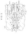
FIG. 5 is a partial sectional view showing connection portions of a body and a supply-side joint in a second embodiment of the invention; -
FIG. 6 is a partial sectional view showing connection portions of a body and a supply-side joint in another example; and -
FIG. 7 is a partial sectional view showing connection portions of a body and a supply-side joint in related art. - (First Embodiment) Hereinafter, a valve device according to a first embodiment will be described with reference to the drawings. A
valve device 1 shown inFIG. 1 is fitted to afitting opening 3 of agas tank 2 in which hydrogen gas at a high pressure (for example, 70MPa) is stored. Thevalve device 1 includes a body 4 (valve body) formed of aluminum alloy, a supply-side joint 6, and a delivery-side joint 8. The supply-side joint 6 serves as a joint that connects, to thevalve device 1, a supply pipe (pipe) 5 extending from a supply source that supplies hydrogen gas. The delivery-side joint 8 connects, to thevalve device 1, adelivery pipe 7 extending to a destination to which the hydrogen gas is delivered (i.e., a delivery destination), for example, a fuel cell. Thebody 4 includes abody portion 11 having a flat box shape, which is disposed outside thegas tank 2, and afitting portion 12 that is inserted into thefitting opening 3. Thefitting portion 12 has a circular columnar shape, and extends in a direction substantially orthogonal to abottom surface 11a of the body portion 11 (i.e., in a downward direction inFIG. 1 ). - In the
body portion 11, asupply passage 13 and adelivery passage 14 are provided. Thesupply passage 13 is provided to supply the hydrogen gas flowing from thesupply pipe 5, into thegas tank 2. Thedelivery passage 14 is provided to deliver the hydrogen gas to the delivery destination such as a fuel cell via thedelivery pipe 7. In thefitting portion 12, aconnection passage 15 is provided. Theconnection passage 15 is connected to each of thesupply passage 13 and thedelivery passage 14, and is opened to the inside of thegas tank 2. That is, in the embodiment, thesupply passage 13 and theconnection passage 15 constitute a gas flow passage that provides communication between the inside and the outside of thegas tank 2. In thesupply passage 13, acheck valve 16 is provided. Thecheck valve 16 suppresses the discharge (release) of the hydrogen gas, which has been supplied into thegas tank 2, to the outside of the body 4 (the outside of the valve device 1). In thedelivery passage 14, asolenoid valve 17 is provided. Thesolenoid valve 17 controls the supply of the hydrogen gas to the delivery destination. In thevalve device 1, thesupply pipe 5 is connected to the supply-side joint 6 such that thesupply pipe 5 is connected to thesupply passage 13, and thedelivery pipe 7 is connected to the delivery-side joint 8 such that thedelivery pipe 7 is connected to thedelivery passage 14. - Next, the configuration of connection portions of the
body 4 and the supply-side joint 6 and the vicinity of the connection portions will be described. As shown inFIG. 2 , aside surface 11b of thebody portion 11, that is, the outer surface of thebody portion 11 has acircular fitting hole 21 that extends in a direction substantially orthogonal to theside surface 11b (i.e., in a right-left direction inFIG. 2 ). Thefitting hole 21 includes a firstfitting hole 22 that is opened at theside surface 11b, and a secondfitting hole 23 that is coaxial with, and adjacent to the firstfitting hole 22. The inside diameter of the firstfitting hole 22 is larger than the inside diameter of the secondfitting hole 23. An internal thread (female thread) is provided on the inner peripheral surface of each of the firstfitting hole 22 and the secondfitting hole 23. The supply-side joint 6 is screwed to the firstfitting hole 22, and thus, the supply-side joint 6 is fitted to the firstfitting hole 22. A positioning member 86 (described later) is screwed to the secondfitting hole 23, and thus, the positioningmember 86 is fitted to the secondfitting hole 23. - The
supply passage 13 linearly extends such that thesupply passage 13 is coaxial with the firstfitting hole 22 and the secondfitting hole 23 in the vicinity of theside surface 11b of thebody portion 11. Thesupply passage 13 is opened to the bottom surface of the secondfitting hole 23. Thus, the inside of thefitting hole 21 communicates with thesupply passage 13. In thesupply passage 13, the above-mentionedcheck valve 16 is provided. - The configuration of the supply-side joint 6 will be described in detail. The supply-
side joint 6 includes a cylindricaljoint body 31. In a through-hole 32 extending through thejoint body 31 in the axial direction of thejoint body 31, asupport member 33, athrottle valve 34, afilter 35, aplug 36, and aseal member 37 are disposed. The through-hole 32 is formed such that the through-hole 32 is coaxial with thesupply passage 13 in a state where thejoint body 31 is fitted to the firstfitting hole 22. - More specifically, as shown in
FIG. 3 , thejoint body 31 includes agrip portion 41 gripped (held) by a tool or the like, a body-side connection portion 42 extending from thegrip portion 41 toward one end side (a left side inFIG. 3 ), and a pipe-side connection portion 43 extending from thegrip portion 41 toward the other end side (a right side inFIG. 3 ). Parts of the outer peripheral surface of thegrip portion 41 are chamfered such that the cross section of thegrip portion 41 in a direction orthogonal to the axial direction has a hexagonal shape. An external thread (a male thread) that is screwed to the internal thread of the firstfitting hole 22 is provided on the outer peripheral surface of the body-side connection portion 42. An external thread (a male thread) that is screwed to an internal thread provided on the inner peripheral surface of thesupply pipe 5 is provided on the outer peripheral surface of the pipe-side connection portion 43. Thus, by screwing the body-side connection portion 42 to the firstfitting hole 22, thejoint body 31 is fitted such that thegrip portion 41 and the pipe-side connection portion 43 protrude from theside surface 11b of thebody portion 11. - The through-
hole 32 provided in thejoint body 31 includes a small-diameter hole portion 46, ataper hole portion 47, a large-diameter hole portion 48, and an increased-diameter hole portion 49 that are arranged in the stated order from the pipe-side connection portion 43-side (the right side inFIG. 3 ) toward the body-side connection portion 42-side. The small-diameter hole portion 46 extends from the end face of the pipe-side connection portion 43 to thegrip portion 41, and the inside diameter of the small-diameter hole portion 46 is smaller than the inside diameter of each of the other portions of the through-hole 32. - The large-
diameter hole portion 48 extends from the end face of the body-side connection portion 42 to a position in thegrip portion 41, the position being close to the pipe-side connection portion 43. The inside diameter of the large-diameter hole portion 48 is larger than the inside diameter of the small-diameter hole portion 46, and is smaller than the inside diameter of the increased-diameter hole portion 49. Thetaper hole portion 47 is disposed between the large-diameter hole portion 48 and the small-diameter hole portion 46. The inside diameter of thetaper hole portion 47 gradually increases in a direction from the small-diameter hole portion 46 toward the large-diameter hole portion 48. The inside diameter of the increased-diameter hole portion 49 is larger than the inside diameter of each of the other portions the through-hole 32. The increased-diameter hole portion 49 is opened at the end face of the body-side connection portion 42. - The
support member 33 is disposed inside the large-diameter hole portion 48. Thesupport member 33 includes a valvechamber forming portion 51, acolumnar portion 52, atubular portion 53, and afitting portion 54 that are arranged in the stated order from the pipe-side connection portion 43-side (the right side inFIG. 3 ). - The valve
chamber forming portion 51 has a bottomed-cylindrical shape, and is opened at the pipe-side connection portion 43-side (i.e., the pipe-side connection portion 43-side of the valvechamber forming portion 51 is opened). The outside diameter of the valvechamber forming portion 51 is substantially equal to the inside diameter of the large-diameter hole portion 48. Thecolumnar portion 52 has a circular columnar shape. The outside diameter of thecolumnar portion 52 is smaller than the outside diameter of the valvechamber forming portion 51. In thecolumnar portion 52, aflow passage 55 is provided. Theflow passage 55 extends through thecolumnar portion 52 in a radial direction of thecolumnar portion 52, and is opened to the bottom surface of the valvechamber forming portion 51. Thetubular portion 53 has a cylindrical shape, and the outside diameter of thetubular portion 53 is smaller than the outside diameter of thecolumnar portion 52. In thetubular portion 53, a plurality ofelongate holes 56 are provided. Theelongate holes 56 extend through thetubular portion 53 from the inside of thetubular portion 53 to the outside of thetubular portion 53, and extend in the axial direction of thetubular portion 53. Thefitting portion 54 has a cylindrical shape, and the outside diameter of thefitting portion 54 is slightly smaller than the outside diameter of thetubular portion 53. - The
throttle valve 34 is disposed inside the valvechamber forming portion 51. Thethrottle valve 34 includes athrottle valve element 62 that makes contact with and separates from athrottle valve seat 61 that is a border portion between the small-diameter hole portion 46 and thetaper hole portion 47, and an urging member 63 (for example, a coil spring) that urges thethrottle valve element 62 toward thethrottle valve seat 61. In the embodiment, the taper hole portion 47-side end (i.e., the taper hole portion 47-side opening) of the small-diameter hole portion 46 functions as a valve orifice of the throttle valve seat 61 (i.e., a throttle valve orifice). - The
throttle valve element 62 includes avalve portion 64, acylindrical portion 65, and anaccommodation tube portion 66 that are arranged in the stated order from the throttle valve seat 61-side (the right side inFIG. 3 ). Thevalve portion 64 has a taper shape, that is, the outside diameter of thevalve portion 64 decreases in a direction away from thecylindrical portion 65. The outside diameter of the largest portion of thevalve portion 64 is smaller than the inside diameter of the large-diameter hole portion 48, and is larger than the inside diameter of the small-diameter hole portion 46. The outside diameter of the smallest portion (i.e., the portion having the smallest diameter) of thevalve portion 64 is smaller than the inside diameter of the small-diameter hole portion 46. Thevalve portion 64 has afine hole 67. Thefine hole 67 is opened at a center of the distal end of thevalve portion 64 and is opened to the inside of thecylindrical portion 65. Thecylindrical portion 65 has a cylindrical shape, and the outside diameter of thecylindrical portion 65 is smaller than the inside diameter of the valvechamber forming portion 51. In thecylindrical portion 65, a plurality of side holes 68 are provided. The side holes 68 extend through thecylindrical portion 65 from the inside of thecylindrical portion 65 to the outside of thecylindrical portion 65. The side holes 68 communicate with thefine hole 67. Theaccommodation tube portion 66 has a cylindrical shape. The outside diameter of theaccommodation tube portion 66 is substantially equal to the inside diameter of the valvechamber forming portion 51. The inside diameter of theaccommodation tube portion 66 is larger than the outside diameter of thecylindrical portion 65. The urgingmember 63 in an axially compressed state is accommodated in theaccommodation tube portion 66. More specifically, the urgingmember 63, which has been brought to the axially compressed state from a state where the length of the urgingmember 63 is a natural length and the force is not accumulated in the urgingmember 63, is accommodated in theaccommodation tube portion 66. Thethrottle valve element 62 is urged toward thethrottle valve seat 61 by the urgingmember 63. - As shown in
FIG. 3 , afilter 35 has a cylindrical shape, and is fitted to the outer periphery of thetubular portion 53. The inside diameter of thefilter 35 is substantially equal to the outside diameter of thetubular portion 53 of thesupport member 33, and the outside diameter of thefilter 35 is smaller than the inside diameter of the large-diameter hole portion 48. In the embodiment, thefilter 35 is constituted by a metal mesh (a wire mesh). Thefilter 35 is disposed to face theelongate holes 56 of thetubular portion 53 in the radial direction in a state whereannular gaskets 71 are disposed on respective sides of thefilter 35 in the axial direction. - A
plug 36 has an annular shape, and is fitted to the outer periphery of thefitting portion 54. The inside diameter of theplug 36 is substantially equal to the outside diameter of thefitting portion 54. The outside diameter of theplug 36 is substantially equal to the inside diameter of the large-diameter hole portion 48 of the through-hole 32. Theplug 36 is disposed in a state where theplug 36 compresses thegaskets 71 provided on respective sides of thefilter 35 in the axial direction. - The
seal member 37 has an annular shape, and is fitted to the increased-diameter hole portion 49. Theseal member 37 is formed of an elastic material such as polyimide resin. Theseal member 37 is interposed (sandwiched) between thejoint body 31 and thebody portion 11 in the state where the joint body 31 (the supply-side joint 6) is fitted to the firstfitting hole 22. Thus, theseal member 37 is in close contact with each of thejoint body 31 and thebody portion 11, and provides airtight sealing between thejoint body 31 and the body portion 11 (the fitting hole 21). - Next, the configuration of the check valve will be described in detail. As shown in
FIG. 2 , thesupply passage 13 includes an increaseddiameter portion 81 and avalve accommodation portion 82 that are provided in the fitting hole 21-side end portion of thesupply passage 13. The increaseddiameter portion 81 is opened to the bottom surface of the secondfitting hole 23. Thevalve accommodation portion 82 is adjacent to the increaseddiameter portion 81, and thecheck valve 16 is accommodated in thevalve accommodation portion 82. The inside diameter of thevalve accommodation portion 82 is smaller than the inside diameter of the increaseddiameter portion 81, and is larger than the inside diameter of the other portion of thesupply passage 13, which is adjacent to thevalve accommodation portion 82. The inner peripheral surface of thevalve accommodation portion 82 is subjected to anodizing treatment. - The
check valve 16 includes acheck valve seat 83 that serves as a valve seat, apoppet 84 that makes contact with and separates from thecheck valve seat 83, and an urging member 85 (for example, a coil spring) that urges thepoppet 84 toward thecheck valve seat 83. Further, thecheck valve 16 in the embodiment includes the positioningmember 86 that sets the position of thecheck valve seat 83 in thesupply passage 13, that is, the gas flow passage. - The
check valve seat 83 is formed of an elastic material such as polyimide resin, and has an annular shape. Thecheck valve seat 83 is fitted in the increaseddiameter portion 81. Acheck valve orifice 87 that extends through thecheck valve seat 83 in the axial direction is provided at a center of thecheck valve seat 83. Thecheck valve orifice 87 is formed such that thecheck valve orifice 87 is disposed coaxially with thesupply passage 13 in a state where thecheck valve seat 83 is fitted to the increaseddiameter portion 81. - The
poppet 84 is formed of stainless steel. Thepoppet 84 includes ablock portion 91, a small-diameter tube portion 92, a large-diameter tube portion 93, and asupport portion 94 that are arranged in the stated order from the check valve seat 83-side (the right side inFIG. 2 ). Theblock portion 91 has a taper shape, that is, the outside diameter of theblock portion 91 decreases in a direction away from the small-diameter tube portion 92. Each of the small-diameter tube portion 92, the large-diameter tube portion 93, and thesupport portion 94 has a cylindrical shape. The small-diameter tube portion 92, the large-diameter tube portion 93, and thesupport portion 94 constitute a hollow shaft. In other words, the portion of thepoppet 84, which consists of the small-diameter tube portion 92, the large-diameter tube portion 93, and thesupport portion 94, is in the form of a hollow shaft. The outside diameter of the largest portion of theblock portion 91 is smaller than the inside diameter of thevalve accommodation portion 82, and is larger than the inside diameter of thecheck valve orifice 87 of thecheck valve seat 83. The outside diameter of the smallest portion ofblock portion 91 is smaller than the inside diameter of thecheck valve orifice 87. When the distal end of theblock portion 91 is inserted in thecheck valve orifice 87 and thus thepoppet 84 is seated at thecheck valve seat 83, thepoppet 84 closes thecheck valve orifice 87. When thepoppet 84 separates from thecheck valve seat 83, thepoppet 84 opens thecheck valve orifice 87. That is, thepoppet 84 closes and opens the supply passage 13 (the gas flow passage) by making contact with and separating from thecheck valve seat 83. - The outside diameter of the small-
diameter tube portion 92 is smaller than the inside diameter of thevalve accommodation portion 82. The small-diameter tube portion 92 has a plurality of side holes 95. The side holes 95 extend through the small-diameter tube portion 92 from the inside of the small-diameter tube portion 92 to the outside of the small-diameter tube portion 92. When the side holes 95 are formed, first, a hole extending in a direction orthogonal to a central axis line O of thepoppet 84 is pierced (formed). Then, in a subsequent process, oblique holes are pierced such that the oblique holes extend in directions intersecting with the direction in which the above-mentioned hole extends and the oblique holes are inclined toward theblock portion 91. That is, by performing this process, the side holes 95 are formed to extend obliquely with respect to the central axis line O of thepoppet 84 such that the side holes 95 extend along gas flow directions inclined with respect to a direction in which thepoppet 84 moves when thecheck valve 16 opens. More specifically, the side holes 95 extend along the gas flow directions (refer to arrows indicating the directions in which the hydrogen gas flows inFIG. 4 ) that are inclined toward the inside of thepoppet 84 with respect to the direction in which thepoppet 84 moves when thecheck valve 16 opens (i.e., a leftward direction inFIG. 4 ). In other words, the side holes 95 are inclined toward the inside of thepoppet 84 with respect to the direction in which thepoppet 84 moves when thecheck valve 16 opens (i.e., the leftward direction inFIG. 4 ).FIG. 2 shows central axis lines O1 of the oblique holes formed in the subsequent process. - In the subsequent processing, it is preferable that the oblique holes should be formed such that the central axis line O1 of each of the oblique holes intersects with the central axis line O. An intersection angle θ of the central axis line O1 of the oblique hole with respect to the central axis line O is, for example, 40° (40 degrees). However, the intersection angle θ is not limited to this value. The intersection angle θ may be in a range of 0° < θ < 90°(the intersection angle θ may be larger than 0° and smaller than 90°). It is preferable that the intersection angle θ should be in a range of 20° ≤ θ ≤ 60° (the intersection angle θ should be equal to or larger than 20° and equal to or smaller than 60°).
- The outside diameter of the large-
diameter tube portion 93 is formed to be substantially equal to the inside diameter of thevalve accommodation portion 82 such that the large-diameter tube portion 93 is in sliding contact with thevalve accommodation portion 82. The outside diameter of thesupport portion 94 is slightly smaller than the outside diameter of the large-diameter tube portion 93. One end of the urgingmember 85 is secured to the bottom surface of thevalve accommodation portion 82, and the other end of the urgingmember 85 is secured to the end face of the large-diameter tube portion 93. Thus, the urgingmember 85 is fitted to the outer periphery of thesupport portion 94 of thepoppet 84. The urgingmember 85 in an axially compressed state is accommodated together with thepoppet 84 in thevalve accommodation portion 82. More specifically, the urgingmember 85, which has been brought to the axially compressed state from a state where the length of the urgingmember 85 is a natural length and the force is not accumulated in the urgingmember 85, is accommodated together with thepoppet 84 in thevalve accommodation portion 82. Thus, thepoppet 84 is urged toward thecheck valve seat 83 by the urgingmember 85. - As shown in
FIG. 2 , the positioningmember 86 has an annular shape. An external thread (a male thread) is provided on the outer periphery of the positioningmember 86. The external thread of the positioningmember 86 is screwed to the internal thread of the secondfitting hole 23. The positioningmember 86 has acommunication hole 97 that extends through the positioningmember 86 in the axial direction. Thecommunication hole 97 is disposed coaxially with thesupply passage 13 in a state where the positioningmember 86 is fitted to the secondfitting hole 23. Thesupply passage 13 communicates with the through-hole 32 of the supply-side joint 6 (the joint body 31) via thecommunication hole 97. Thus, the supply-side joint 6 and the positioningmember 86 are fitted to the fitting hole 21 (the firstfitting hole 22 and the second fitting hole 23) such that the supply-side joint 6 and the positioningmember 86 are coaxially arranged in the stated order from the outer side (i.e., theside surface 11b-side) of the body 4 (the body portion 11). - The length of the positioning
member 86 in the axial direction is substantially equal to the depth of the second fitting hole 23 (i.e., the length of the secondfitting hole 23 in the right-left direction inFIG. 2 ). Thus, the positioningmember 86 does not protrude into firstfitting hole 22 in a state where the positioningmember 86 is fitted to the secondfitting hole 23. That is, the positioningmember 86 does not overlap with the supply-side joint 6 in the radial direction of thefitting hole 21. In other words, the axial position of the positioningmember 86 does not overlap with the axial direction of the supply-side joint 6 in the axial direction (i.e., in the depth direction) of thefitting hole 21. - In the state where the positioning
member 86 is fitted to the secondfitting hole 23, the positioningmember 86 presses thecheck valve seat 83 to a connectingsurface 98 between the increaseddiameter portion 81 and the valve accommodation portion 82 (i.e., the connectingsurface 98 connecting the inner peripheral surface of the increaseddiameter portion 81 and the inner peripheral surface of thevalve accommodation portion 82 that have inside diameters different from each other), thereby setting (fixing) the position of thecheck valve seat 83 in the supply passage 13 (the gas flow passage). That is, the position of thecheck valve seat 83 in thesupply passage 13 is set (fixed) by the positioningmember 86 that is a member formed separately from the supply-side joint 6. Thus, even in a state where the supply-side joint 6 is not fitted to thefitting hole 21, the positioningmember 86 is able to set the position of thecheck valve seat 83 in thesupply passage 13. Further, thecheck valve seat 83 is interposed between the positioningmember 86 and the body portion 11 (the valve accommodation portion 82). In other words, thecheck valve seat 83 is disposed in a region defined by the positioningmember 86 and the body portion 11 (the increased diameter portion 81). Thus, thecheck valve seat 83 is in close contact with each of thebody portion 11 and the positioningmember 86, and thecheck valve seat 83 provides airtight sealing between thebody portion 11 and the positioningmember 86. - (Operation in the first embodiment) Next, the operation of the valve device according to the embodiment will be described. When hydrogen gas is supplied into the
gas tank 2, thesupply pipe 5 is connected to the supply-side joint 6 such that the hydrogen gas is delivered into the supply-side joint 6 as shown inFIG. 2 . At this time, thethrottle valve element 62 of thethrottle valve 34 shown inFIG. 3 moves toward thebody 4 against the urging force of the urgingmember 63, and thus, thethrottle valve element 62 separates from thethrottle valve seat 61. Thus, a large amount of hydrogen gas flows into the valvechamber forming portion 51 of thesupport member 33 via the small-diameter hole portion 46. The hydrogen gas, which has flowed into the valvechamber forming portion 51, flows into thesupply passage 13, via the side holes 68 provided in thethrottle valve element 62, theflow passage 55 provided in thecolumnar portion 52 of thesupport member 33, thefilter 35, theelongate holes 56 provided in thetubular portion 53, and thecommunication hole 97 of the positioningmember 86. - Then, as shown in
FIG. 4 , due to the pressure of the hydrogen gas, thepoppet 84 of thecheck valve 16 moves toward the inner side of thesupply passage 13 against the urging force of the urgingmember 85, and thus, thepoppet 84 separates from thecheck valve seat 83. InFIG. 4 , the arrows indicate the directions in which the hydrogen gas flows, as described above. - Thus, the hydrogen gas flows into the
valve accommodation portion 82, and flows into thepoppet 84 through the side holes 95. The side holes 95 extend obliquely with respect to the central axis line O of thepoppet 84 such that the side holes 95 extend along the gas flow directions inclined with respect to the direction in which thepoppet 84 moves when thecheck valve 16 opens. Therefore, the flows of the gas introduced into thepoppet 84 through the side holes 95 smoothly merge together. As a result, as compared to related art in which the central axis line of theside hole 95 is orthogonal to the central axis line O, the dynamic pressure drop (the dynamic pressure loss) in thepoppet 84 is reduced, and the fluctuation of the gas flow in thepoppet 84 is suppressed. The hydrogen gas, which has passed through thepoppet 84, flows into thegas tank 2 via thesupply passage 13 and theconnection passage 15. - Even in the case where the gas flow rate decreases and thus the load pushing the poppet decreases, and the balance between the load and the restoring force of the urging
member 85 is lost, the flows of the gas introduced into thepoppet 84 through the side holes 95 smoothly merge together. Therefore, the fluctuation of the gas flow in thepoppet 84 is suppressed, and as a result, chattering of thepoppet 84 is suppressed. - When hydrogen gas is not supplied into the
gas tank 2, thepoppet 84 is urged toward thecheck valve seat 83 due to the pressure of the hydrogen gas in the gas tank 2 (the supply passage 13) and the urging force of the urgingmember 85, and thus, thepoppet 84 is seated at thecheck valve seat 83. Thus, thecheck valve orifice 87 of thecheck valve seat 83 is closed, and the discharge (release) of the hydrogen gas from thegas tank 2 to the outside of thebody 4 is suppressed. Thethrottle valve element 62 is seated at thethrottle valve seat 61 due to the urging force of the urgingmember 63. As shown inFIG. 3 , thethrottle valve element 62 has thefine hole 67. Therefore, even in a state where thethrottle valve element 62 is seated at thethrottle valve seat 61, the flow of the hydrogen gas is not completely blocked. Thus, thethrottle valve 34 functions as an excess flow stop valve that allows a small amount of hydrogen gas to flow from the large-diameter hole portion 48 to the small-diameter hole portion 46. Therefore, for example, when damage or the like occurs in thepoppet 84 of thecheck valve 16, a small amount of hydrogen gas is discharged through thethrottle valve 34, and thus, an operator can detect a failure in the valve device 1 (the check valve 16). - There may be a case where the operator accidentally removes the supply-side joint 6 (the joint body 31) from the
fitting hole 21, for example, after hydrogen gas is supplied. Even in this case, the position of thecheck valve seat 83 is maintained, because the positioningmember 86 remains screwed to the secondfitting hole 23. Therefore, it is possible to suppress the occurrence of a situation where thepoppet 84 cannot tightly close thecheck valve orifice 87, or thecheck valve seat 83 cannot remain in close contact with each of thebody portion 11 and the positioningmember 86 due to the displacement of the position of thecheck valve seat 83. Thus, the function of thecheck valve 16 is maintained. - There may be a case where a vehicle collision or the like occurs and a vehicle wheel or the like hits the outer peripheral surface of the supply-side joint 6 in a direction substantially orthogonal to the axial direction of the supply-
side joint 6. In this case, due to the impact caused by the collision with the vehicle wheel or the like, for example, the supply-side joint 6 may be deformed, and may be inclined in the firstfitting hole 22. In this regard, in thevalve device 1 according to the embodiment, the axial position of the supply-side joint 6 and the axial position of the positioningmember 86 do not overlap with each other in the axial direction of thefitting hole 21. Therefore, when the supply-side joint 6 is inclined due to an impact, the supply-side joint 6 is unlikely to interfere with the positioningmember 86. Further, in thevalve device 1 according to the embodiment, the inside diameter of the secondfitting hole 23 is smaller than the inside diameter of the firstfitting hole 22 as described above, and there is a step (in other words, a level difference) between the inner peripheral surface of the firstfitting hole 22 and the inner peripheral surface of the secondfitting hole 23. Therefore, even when the firstfitting hole 22 is deformed due to the impact, the deformation of the firstfitting hole 22 is unlikely to influence the secondfitting hole 23. Accordingly, even when a large impact is applied to the supply-side joint 6, the displacement of the position of the positioningmember 86 in the secondfitting hole 23 is suppressed. - Next, the effects of the embodiment will be described. (1) The
valve device 1 according to the embodiment includes thebody 4 and thecheck valve 16. In thebody 4, thesupply passage 13 and theconnection passage 15 are provided (i.e., the gas flow passage is provided), thesupply passage 13 and theconnection passage 15 providing communication between the inside and the outside of thegas tank 2. Thecheck valve 16 includes thepoppet 84 that suppresses the discharge of the gas inside thegas tank 2 to the outside of thebody 4, and thecheck valve seat 83. - The
poppet 84 excluding theblock portion 91 is in the form of a hollow shaft, theblock portion 91 being located at the distal end of thepoppet 84 and having a taper shape. Thepoppet 84 has the side holes 95 that provide communication between the inside and the outside of the portion of thepoppet 84, the portion being in the form of the hollow shaft. Further, the side holes 95 extend obliquely with respect to the central axis line O of thepoppet 84 such that the side holes 95 extend along the gas flow directions inclined with respect to the direction in which thepoppet 84 moves when thecheck valve 16 opens. As a result, it is possible to suppress the occurrence of noise due to chattering of the poppet when the gas flow rate is low. - (2) In the
valve device 1 according to the embodiment, the outer surface of thebody 4 has thefitting hole 21 that leads to the supply passage 13 (the gas flow passage). In thefitting hole 21, the supply-side joint 6 and the positioningmember 86 are arranged and fitted in the stated order from the outer side of thebody 4. The supply-side joint 6 connects the pipe to the supply passage 13 (the gas flow passage). The positioningmember 86 has thecommunication hole 97 that communicates with the supply passage 13 (the gas flow passage). The positioningmember 86 is configured such that the positioningmember 86 is able to set the position of thecheck valve seat 83 even in the state where the supply-side joint 6 is not fitted to thefitting hole 21. Therefore, for example, when the operator accidentally removes the supply-side joint 6, the position of thecheck valve seat 83 is maintained, and the function of thecheck valve 16 can be maintained. - (3) The axial position of the supply-
side joint 6 and the axial position of the positioningmember 86 do not overlap with each other in the axial direction of thefitting hole 21. Therefore, when a large impact is applied to the supply-side joint 6, it is possible to suppress the displacement of the position of the positioningmember 86 in thefitting hole 21 caused by the interference with the supply-side joint 6. Thus, it is possible to appropriately maintain the position of thecheck valve seat 83. - (4) The
fitting hole 21 includes the firstfitting hole 22 and the secondfitting hole 23 having the inside diameter smaller than the inside diameter of the firstfitting hole 22. Therefore, when a large impact is applied to the supply-side joint 6, it is possible to suppress the displacement of the position of the positioningmember 86 in the secondfitting hole 23 caused by the deformation of the firstfitting hole 22. Thus, it is possible to more appropriately maintain the position of thecheck valve seat 83. - (Second Embodiment) Next, a valve device according to a second embodiment will be described with reference to
FIG. 5 . For the sake of illustration, the portions that are the same or correspond to those in the first embodiment will be denoted by the same reference numerals, and the descriptions thereof will be omitted. - As shown in
FIG. 5 , the inside diameter of thefitting hole 21 is substantially constant over the entirefitting hole 21 in the axial direction (i.e., in the depth direction) of thefitting hole 21. An internal thread (a female thread) is provided on the inner peripheral surface of thefitting hole 21. Thejoint body 31 of the supply-side joint 6 and the positioningmember 86 are screwed to the internal thread, and thus, thejoint body 31 and the positioningmember 86 are fitted to thefitting hole 21. Thejoint body 31 includes a cylindrical extendingportion 101 that further extends from the body-side connection portion 42. The outside diameter of the extendingportion 101 is smaller than the outside diameter of the body-side connection portion 42. The through-hole 32 of thejoint body 31 does not include the increased-diameter hole portion 49 in the above-mentioned first embodiment. - The positioning
member 86 includes atube portion 103 having a bottomed cylindrical shape. An external thread (a male thread) provided on the outer periphery of thetube portion 103 is screwed to the internal thread of thefitting hole 21. The inside diameter of thetube portion 103 is substantially equal to the outside diameter of extendingportion 101 of thejoint body 31. The extendingportion 101 is inserted in thetube portion 103. That is, the positioningmember 86 in the embodiment overlaps with the supply-side joint 6 in the radial direction of thefitting hole 21. In other words, the axial position of the positioningmember 86 and the axial position of the supply-side joint 6 overlap with each other in the axial direction of thefitting hole 21. In abottom portion 105 of the positioningmember 86, acommunication hole 106 is provided. Thecommunication hole 106 extends through thebottom portion 105 in the axial direction of the positioningmember 86. Thecommunication hole 106 is formed such that thecommunication hole 106 is disposed coaxially with thesupply passage 13 in the state where the positioningmember 86 is fitted to thefitting hole 21. - The
plug 36 includes aninsertion portion 111, and aflange portion 112 that is provided on a side of theinsertion portion 111, the side being close to the positioningmember 86. Anaxial hole 113 that extends through theplug 36 in the axial direction of theplug 36 is provided at a center of theplug 36. The outside diameter of theinsertion portion 111 is substantially equal to the inside diameter of the large-diameter hole portion 48 of thejoint body 31. Anannular groove 114 that extends in the circumferential direction of theinsertion portion 111 is provided on the outer peripheral surface of theinsertion portion 111. An O-ring 115 and abackup ring 116 are fitted to theannular groove 114. Thus, airtight sealing is provided between theplug 36 and thejoint body 31. The outside diameter of theflange portion 112 is substantially equal to the inside diameter of thetube portion 103 of the positioningmember 86. Theflange portion 112 faces the extendingportion 101 of thejoint body 31 in the axial direction. An increaseddiameter hole portion 117 is provided in the flange portion 112-side end portion (i.e., the left end portion inFIG. 5 ) of theaxial hole 113. The inside diameter of the increaseddiameter hole portion 117 is larger than the inside diameter of the other portion of theaxial hole 113. - The
seal member 37 is fitted in the increaseddiameter hole portion 117. In a state in which thejoint body 31 is fitted to thefitting hole 21, the extendingportion 101 presses theflange portion 112 such that theseal member 37 is interposed (sandwiched) between theplug 36 and the positioningmember 86. Thus, theseal member 37 is in close contact with each of theplug 36 and the positioningmember 86, and thus, airtight sealing is provided between the positioningmember 86 and theplug 36. - According to the second embodiment, it is possible to obtain the effect of the first embodiment described in the above-mentioned section (1). Each of the above-mentioned embodiments may be appropriately modified. Modified examples of each of the above-mentioned embodiments will be described below.
- In each of the above-mentioned embodiments, the side holes 95 of the
poppet 84 are formed by piercing (forming) the hole extending in the direction orthogonal to the central axis line O of thepoppet 84, and then, piercing (forming) the oblique holes extending in the directions intersecting with the direction in which the above-mentioned hole extends, in the small-diameter tube portion 92 of thepoppet 84. - The side holes 95 may be formed by forming the oblique holes whose central axis lines O1 obliquely intersect with the central axis line O of the
poppet 84, in the small-diameter tube portion 92 of thepoppet 84, instead of forming the hole extending in the direction orthogonal to the central axis line O and then forming the oblique holes. That is, the formation of the hole extending in the direction orthogonal to the central axis line O may be omitted. Further, the number of the side holes 95 is not particularly limited. That is, the number of the side holes (oblique holes) 95 may be one, or two or more. - In the first embodiment, the
fitting hole 21 includes the firstfitting hole 22 and the secondfitting hole 23 that have the inside diameters different from each other. However, the invention is not limited to this configuration. The inside diameter of thefitting hole 21 may be substantially constant over the entirefitting hole 21 in the depth direction (the axial direction) of thefitting hole 21. - In the first embodiment, the
check valve 16 includes the annularcheck valve seat 83 that is a member formed separately from the positioningmember 86. However, the invention is not limited to this configuration. For example, as shown inFIG. 6 , the positioningmember 86 may be formed of an elastic material such as polyimide resin, and thepoppet 84 may close and open thecommunication hole 97 of the positioning member 86 (i.e., the check valve orifice) by making contact with and separating from the positioningmember 86. That is, the positioningmember 86 may function also as the check valve seat. Similarly, in the second embodiment, the positioningmember 86 may function also as the check valve seat. - In the example shown in
FIG. 6 , the positioningmember 86 may be formed of soft metal that is elastically deformable, for example, brass or copper alloy. In each of the above-mentioned embodiments, each of thecheck valve seat 83 and theseal member 37 may be formed of soft metal. - In each of the above-mentioned embodiments, the
joint body 31 and the positioningmember 86 are screwed to the fitting hole 21 (the firstfitting hole 22 and the second fitting hole 23). However, the invention is not limited to this configuration. For example, thejoint body 31 and the positioningmember 86 may be press-fitted into thefitting hole 21. - In each of the above-mentioned embodiments, the
throttle valve 34 may not be provided in the supply-side joint 6. In each of the above-mentioned embodiments, the coil spring is used as each of the urgingmembers members poppet 84 can be urged toward thecheck valve seat 83 by the pressure of hydrogen gas, the urgingmember 85 may not be provided, and in the case where thethrottle valve element 62 can be urged toward thethrottle valve seat 61 by the pressure of hydrogen gas, the urgingmember 63 may not be provided. - In each of the above-mentioned embodiments, the
valve device 1 is fitted to thegas tank 2 in which hydrogen gas is stored. However, the invention is not limited to this configuration. Thevalve device 1 may be fitted to a gas tank in which gas other than hydrogen gas is stored.
Claims (4)
- A valve device configured to be fitted to a gas tank in which high-pressure gas is stored, the valve device characterized by comprising:a body (4) in which a gas flow passage is provided, the gas flow passage providing communication between an inside and an outside of the gas tank; anda check valve (16) provided in the gas flow passage, the check valve (16) including a poppet (84) that suppresses discharge of the gas inside the gas tank to an outside of the body (4), and a valve seat with which the poppet (84) makes contact and from which the poppet (84) separates, wherein:the poppet (84) excluding a block portion (91) is in a form of a hollow shaft, the block portion (91) being located at a distal end of the poppet (84) and having a taper shape, and the poppet (84) has at least one side hole (95) that provides communication between an inside and an outside of a portion of the poppet (84), the portion being in the form of the hollow shaft; andthe at least one side hole (95) extends obliquely with respect to a central axis line of the poppet (84) such that the at least one side hole (95) extends along a gas flow direction inclined with respect to a direction in which the poppet (84) moves when the check valve (16) opens.
- The valve device according to claim 1, wherein
an intersection angle of a central axis line of each of the at least one side hole (95) with respect to the central axis line of the poppet (84) is equal to or larger than 20° and equal to or smaller than 60°. - The valve device according to claim 1, characterized by further comprising:a joint (6) connecting a pipe to the gas flow passage; anda positioning member (86) having a communication hole (97) that communicates with the gas flow passage, wherein:an outer surface of the body (4) has a fitting hole (21) that leads to the gas flow passage;in the fitting hole (21), the joint (6) and the positioning member (86) are arranged in a stated order from an outer side of the body (4); andthe positioning member (86) is configured such that the positioning member (86) is able to set a position of the valve seat even in a state where the joint (6) is not fitted to the fitting hole (21).
- The valve device according to claim 3, wherein:the gas flow passage includes an increased diameter portion (81) in which the valve seat is fitted, and a valve accommodation portion (82) in which the poppet (84) is accommodated;an inside diameter of the valve accommodation portion (82) is smaller than an inside diameter of the increased diameter portion (81); andthe positioning member (86) sets the position of the valve seat by pressing the valve seat to a connecting surface (98) that connects an inner peripheral surface of the increased diameter portion (81) and an inner peripheral surface of the valve accommodation portion (82).
Applications Claiming Priority (1)
| Application Number | Priority Date | Filing Date | Title |
|---|---|---|---|
| JP2014207253A JP6373713B2 (en) | 2014-10-08 | 2014-10-08 | Valve device |
Publications (2)
| Publication Number | Publication Date |
|---|---|
| EP3006791A1 true EP3006791A1 (en) | 2016-04-13 |
| EP3006791B1 EP3006791B1 (en) | 2017-11-15 |
Family
ID=54291128
Family Applications (1)
| Application Number | Title | Priority Date | Filing Date |
|---|---|---|---|
| EP15188824.5A Active EP3006791B1 (en) | 2014-10-08 | 2015-10-07 | Valve device |
Country Status (6)
| Country | Link |
|---|---|
| US (1) | US9995406B2 (en) |
| EP (1) | EP3006791B1 (en) |
| JP (1) | JP6373713B2 (en) |
| KR (1) | KR102392776B1 (en) |
| CN (1) | CN105508874B (en) |
| CA (1) | CA2908456C (en) |
Cited By (3)
| Publication number | Priority date | Publication date | Assignee | Title |
|---|---|---|---|---|
| EP3006791B1 (en) * | 2014-10-08 | 2017-11-15 | Jtekt Corporation | Valve device |
| DE102017213524A1 (en) * | 2017-08-03 | 2019-02-07 | Bayerische Motoren Werke Aktiengesellschaft | Valve device for a pressure vessel of a pressure vessel system with a plurality of pressure vessels |
| US10487949B2 (en) | 2015-12-07 | 2019-11-26 | Nitto Kohki Co., Ltd. | Coupling member |
Families Citing this family (14)
| Publication number | Priority date | Publication date | Assignee | Title |
|---|---|---|---|---|
| DE102014001306A1 (en) * | 2014-01-31 | 2015-08-06 | GM Global Technology Operations LLC (n. d. Gesetzen des Staates Delaware) | Valve device and motor vehicle |
| JP6421013B2 (en) * | 2014-10-28 | 2018-11-07 | 株式会社ジェイテクト | Throttle valve |
| JP6498510B2 (en) * | 2015-04-27 | 2019-04-10 | 株式会社ジェイテクト | Valve device and poppet |
| CN106150431B (en) * | 2016-08-10 | 2018-10-26 | 中国石油大学(华东) | The anti-blocking precise controlling regulating valve of coal bed gas well |
| JP6765935B2 (en) | 2016-10-31 | 2020-10-07 | 株式会社ジェイテクト | Valve device |
| JP2018088869A (en) * | 2016-12-02 | 2018-06-14 | アグリテクノ矢崎株式会社 | Check valve for soil sterilizer |
| JP6916033B2 (en) * | 2017-04-24 | 2021-08-11 | 株式会社Soken | solenoid valve |
| JP7084198B2 (en) * | 2018-04-20 | 2022-06-14 | 株式会社ジェイテクト | Valve device |
| KR102233466B1 (en) * | 2018-10-02 | 2021-03-31 | 세메스 주식회사 | Apparatus for treating subastrate and safety valve thereof |
| CN109630479A (en) * | 2018-12-13 | 2019-04-16 | 山东大学 | A kind of nozzle, the adjustable injector of the discharge characteristic based on the nozzle and its application |
| KR20200081850A (en) | 2018-12-28 | 2020-07-08 | 신화하이텍 주식회사 | A high pressure check valve for hydrogen transfer |
| JP7275682B2 (en) * | 2019-03-14 | 2023-05-18 | 株式会社ジェイテクト | valve device |
| KR102108100B1 (en) * | 2019-12-06 | 2020-05-07 | 김석 | High Pressure Gas ON-OFF Valve |
| KR102521583B1 (en) * | 2021-12-16 | 2023-04-13 | 한국자동차연구원 | Double Check Valve |
Citations (10)
| Publication number | Priority date | Publication date | Assignee | Title |
|---|---|---|---|---|
| US2123477A (en) * | 1937-04-19 | 1938-07-12 | John M Sheedy | Valve |
| GB502554A (en) * | 1936-06-19 | 1939-03-20 | Int Hydrogenation Patents Co | Shut-off valves |
| DE1236291B (en) * | 1961-02-13 | 1967-03-09 | Industriegeraete Fuer Energiet | Fine control and safety valve for flow regulators in oil heating systems |
| US3770009A (en) * | 1971-12-29 | 1973-11-06 | Victor Equipment Co | Sensitive check valve |
| FR2707603A1 (en) * | 1993-06-29 | 1995-01-20 | Staubli Sa Ets | Safety stopper for valve nozzles intended for filling tanks with fluid under high pressure |
| WO1999008028A1 (en) * | 1997-08-08 | 1999-02-18 | Fmc Corporation | Metal seals for check valves |
| DE102010003192A1 (en) * | 2010-03-24 | 2011-09-29 | Man Diesel & Turbo Se | Valve, particularly suction valve, delivery valve or fuel valve for fuel supply system of internal combustion engine, particularly common rail fuel supply system of marine diesel engine, has valve body cooperating with spring element |
| JP2013029160A (en) * | 2011-07-28 | 2013-02-07 | Jtekt Corp | Valve device |
| JP2013029161A (en) | 2011-07-28 | 2013-02-07 | Jtekt Corp | Joint and valve device |
| EP2833037A2 (en) * | 2013-08-02 | 2015-02-04 | Jtekt Corporation | Valve unit |
Family Cites Families (25)
| Publication number | Priority date | Publication date | Assignee | Title |
|---|---|---|---|---|
| US1363623A (en) * | 1920-12-28 | Valve eob air-cooled spabk-pltjgs | ||
| US2234932A (en) * | 1937-11-20 | 1941-03-11 | Timken Roller Bearing Co | Fuel injection delivery valve |
| US2306012A (en) | 1941-06-11 | 1942-12-22 | John Eley Jr | Check valve |
| US2675021A (en) * | 1952-10-24 | 1954-04-13 | Weatherhead Co | Check valve |
| US2930401A (en) * | 1956-11-16 | 1960-03-29 | Bobrick Mfg Corp | Poppet valve construction |
| US3099999A (en) * | 1961-03-06 | 1963-08-06 | Holley Carburetor Co | Check valve |
| US4213021A (en) * | 1979-01-19 | 1980-07-15 | Aeroquip Corporation | Indicating check valve |
| US4287912A (en) * | 1980-03-24 | 1981-09-08 | Kem-O-Kleen, Inc. | Monoflow ball valve and system |
| DE10115162C1 (en) * | 2001-03-27 | 2002-10-02 | Orange Gmbh | Pressure relief valve for fuel injectors |
| PL1604135T3 (en) * | 2003-03-20 | 2010-02-26 | Bosch Rexroth Ag | Non-return valve |
| DE10316230B4 (en) * | 2003-03-20 | 2014-03-27 | Bosch Rexroth Aktiengesellschaft | check valve |
| DE102004058302A1 (en) * | 2004-09-17 | 2006-03-23 | Bosch Rexroth Aktiengesellschaft | Sealing bush, hydraulic device and check valve |
| JP4579657B2 (en) * | 2004-11-17 | 2010-11-10 | 株式会社ジェイテクト | Valve device fixing structure and manual valve |
| JP2009079623A (en) * | 2007-09-25 | 2009-04-16 | Jtekt Corp | Valve device and manual opening and closing valve device |
| JP5272785B2 (en) * | 2009-02-17 | 2013-08-28 | 株式会社ジェイテクト | Valve device |
| JP5439848B2 (en) * | 2009-02-17 | 2014-03-12 | 株式会社ジェイテクト | Valve device |
| KR101165795B1 (en) * | 2009-07-30 | 2012-07-17 | (주)에쎈테크 | Valve for gas container |
| JP2011094641A (en) * | 2009-10-27 | 2011-05-12 | Toyota Motor Corp | Check valve mechanism for charging high-pressure gas |
| DE102009046958A1 (en) * | 2009-11-23 | 2011-05-26 | Robert Bosch Gmbh | Valve for reducing pressure pulsations or noise emissions in piston pump for hydraulic- or pneumatic system, has valve closure body and valve seat for piston pump |
| US20130180592A1 (en) * | 2011-09-12 | 2013-07-18 | Baker Hughes Incorporated | Valve for Use in Chemical Injectors and the Like |
| EP2728161A1 (en) * | 2012-11-05 | 2014-05-07 | Delphi Technologies Holding S.à.r.l. | Outlet Valve Assembly |
| GB2509077B (en) * | 2012-12-19 | 2019-08-28 | Forum Energy Tech Uk Limited | Self-regulating surplussing check valve |
| JP6373713B2 (en) * | 2014-10-08 | 2018-08-15 | 株式会社ジェイテクト | Valve device |
| JP6490382B2 (en) * | 2014-10-10 | 2019-03-27 | 株式会社ジェイテクト | Valve device |
| JP6421013B2 (en) * | 2014-10-28 | 2018-11-07 | 株式会社ジェイテクト | Throttle valve |
-
2014
- 2014-10-08 JP JP2014207253A patent/JP6373713B2/en active Active
-
2015
- 2015-10-06 US US14/876,580 patent/US9995406B2/en active Active
- 2015-10-06 CA CA2908456A patent/CA2908456C/en active Active
- 2015-10-07 EP EP15188824.5A patent/EP3006791B1/en active Active
- 2015-10-07 KR KR1020150140802A patent/KR102392776B1/en active IP Right Grant
- 2015-10-08 CN CN201510646549.2A patent/CN105508874B/en active Active
Patent Citations (10)
| Publication number | Priority date | Publication date | Assignee | Title |
|---|---|---|---|---|
| GB502554A (en) * | 1936-06-19 | 1939-03-20 | Int Hydrogenation Patents Co | Shut-off valves |
| US2123477A (en) * | 1937-04-19 | 1938-07-12 | John M Sheedy | Valve |
| DE1236291B (en) * | 1961-02-13 | 1967-03-09 | Industriegeraete Fuer Energiet | Fine control and safety valve for flow regulators in oil heating systems |
| US3770009A (en) * | 1971-12-29 | 1973-11-06 | Victor Equipment Co | Sensitive check valve |
| FR2707603A1 (en) * | 1993-06-29 | 1995-01-20 | Staubli Sa Ets | Safety stopper for valve nozzles intended for filling tanks with fluid under high pressure |
| WO1999008028A1 (en) * | 1997-08-08 | 1999-02-18 | Fmc Corporation | Metal seals for check valves |
| DE102010003192A1 (en) * | 2010-03-24 | 2011-09-29 | Man Diesel & Turbo Se | Valve, particularly suction valve, delivery valve or fuel valve for fuel supply system of internal combustion engine, particularly common rail fuel supply system of marine diesel engine, has valve body cooperating with spring element |
| JP2013029160A (en) * | 2011-07-28 | 2013-02-07 | Jtekt Corp | Valve device |
| JP2013029161A (en) | 2011-07-28 | 2013-02-07 | Jtekt Corp | Joint and valve device |
| EP2833037A2 (en) * | 2013-08-02 | 2015-02-04 | Jtekt Corporation | Valve unit |
Cited By (3)
| Publication number | Priority date | Publication date | Assignee | Title |
|---|---|---|---|---|
| EP3006791B1 (en) * | 2014-10-08 | 2017-11-15 | Jtekt Corporation | Valve device |
| US10487949B2 (en) | 2015-12-07 | 2019-11-26 | Nitto Kohki Co., Ltd. | Coupling member |
| DE102017213524A1 (en) * | 2017-08-03 | 2019-02-07 | Bayerische Motoren Werke Aktiengesellschaft | Valve device for a pressure vessel of a pressure vessel system with a plurality of pressure vessels |
Also Published As
| Publication number | Publication date |
|---|---|
| US20160102771A1 (en) | 2016-04-14 |
| JP2016075373A (en) | 2016-05-12 |
| EP3006791B1 (en) | 2017-11-15 |
| CA2908456A1 (en) | 2016-04-08 |
| KR20160041811A (en) | 2016-04-18 |
| KR102392776B1 (en) | 2022-05-02 |
| CN105508874A (en) | 2016-04-20 |
| JP6373713B2 (en) | 2018-08-15 |
| CN105508874B (en) | 2020-05-12 |
| CA2908456C (en) | 2021-05-11 |
| US9995406B2 (en) | 2018-06-12 |
Similar Documents
| Publication | Publication Date | Title |
|---|---|---|
| EP3006791B1 (en) | Valve device | |
| EP3015756B1 (en) | Throttle valve | |
| EP2833037B1 (en) | Valve unit | |
| CN105508875B (en) | Valve device | |
| KR102445153B1 (en) | Pressure reducing valve | |
| JP2009079623A (en) | Valve device and manual opening and closing valve device | |
| WO2013115120A1 (en) | Filling port structure for pressure fluid | |
| JP4293371B2 (en) | Relief valve | |
| US10767772B2 (en) | Seal with integrated fluid regulating device | |
| US10234050B2 (en) | Check valve | |
| US20190316698A1 (en) | Pressure reducing valve | |
| JP5970426B2 (en) | Pressure operating valve and setting method of set pressure in pressure operating valve | |
| EP3557115A1 (en) | Valve device | |
| JP5611438B1 (en) | Structure | |
| JP2021162110A (en) | Check valve and fluid supply system |
Legal Events
| Date | Code | Title | Description |
|---|---|---|---|
| PUAI | Public reference made under article 153(3) epc to a published international application that has entered the european phase |
Free format text: ORIGINAL CODE: 0009012 |
|
| AK | Designated contracting states |
Kind code of ref document: A1 Designated state(s): AL AT BE BG CH CY CZ DE DK EE ES FI FR GB GR HR HU IE IS IT LI LT LU LV MC MK MT NL NO PL PT RO RS SE SI SK SM TR |
|
| AX | Request for extension of the european patent |
Extension state: BA ME |
|
| 17P | Request for examination filed |
Effective date: 20161010 |
|
| RBV | Designated contracting states (corrected) |
Designated state(s): AL AT BE BG CH CY CZ DE DK EE ES FI FR GB GR HR HU IE IS IT LI LT LU LV MC MK MT NL NO PL PT RO RS SE SI SK SM TR |
|
| RIC1 | Information provided on ipc code assigned before grant |
Ipc: F17C 13/04 20060101ALI20170418BHEP Ipc: F16K 1/42 20060101AFI20170418BHEP Ipc: F16K 15/02 20060101ALI20170418BHEP |
|
| GRAP | Despatch of communication of intention to grant a patent |
Free format text: ORIGINAL CODE: EPIDOSNIGR1 |
|
| INTG | Intention to grant announced |
Effective date: 20170620 |
|
| GRAS | Grant fee paid |
Free format text: ORIGINAL CODE: EPIDOSNIGR3 |
|
| GRAA | (expected) grant |
Free format text: ORIGINAL CODE: 0009210 |
|
| AK | Designated contracting states |
Kind code of ref document: B1 Designated state(s): AL AT BE BG CH CY CZ DE DK EE ES FI FR GB GR HR HU IE IS IT LI LT LU LV MC MK MT NL NO PL PT RO RS SE SI SK SM TR |
|
| REG | Reference to a national code |
Ref country code: CH Ref legal event code: EP Ref country code: GB Ref legal event code: FG4D Ref country code: AT Ref legal event code: REF Ref document number: 946625 Country of ref document: AT Kind code of ref document: T Effective date: 20171115 |
|
| RIN1 | Information on inventor provided before grant (corrected) |
Inventor name: INAGI, SHUSUKE Inventor name: YAMASHITA, AKIRA Inventor name: HANEDA, KAZUO Inventor name: KUROYANAGI, MUNETOSHI Inventor name: NAKAMURA, AKIO Inventor name: KONDO, MASAAKI |
|
| REG | Reference to a national code |
Ref country code: IE Ref legal event code: FG4D |
|
| REG | Reference to a national code |
Ref country code: DE Ref legal event code: R096 Ref document number: 602015005995 Country of ref document: DE |
|
| REG | Reference to a national code |
Ref country code: NL Ref legal event code: MP Effective date: 20171115 |
|
| REG | Reference to a national code |
Ref country code: LT Ref legal event code: MG4D |
|
| REG | Reference to a national code |
Ref country code: AT Ref legal event code: MK05 Ref document number: 946625 Country of ref document: AT Kind code of ref document: T Effective date: 20171115 |
|
| PG25 | Lapsed in a contracting state [announced via postgrant information from national office to epo] |
Ref country code: NL Free format text: LAPSE BECAUSE OF FAILURE TO SUBMIT A TRANSLATION OF THE DESCRIPTION OR TO PAY THE FEE WITHIN THE PRESCRIBED TIME-LIMIT Effective date: 20171115 Ref country code: NO Free format text: LAPSE BECAUSE OF FAILURE TO SUBMIT A TRANSLATION OF THE DESCRIPTION OR TO PAY THE FEE WITHIN THE PRESCRIBED TIME-LIMIT Effective date: 20180215 Ref country code: ES Free format text: LAPSE BECAUSE OF FAILURE TO SUBMIT A TRANSLATION OF THE DESCRIPTION OR TO PAY THE FEE WITHIN THE PRESCRIBED TIME-LIMIT Effective date: 20171115 Ref country code: FI Free format text: LAPSE BECAUSE OF FAILURE TO SUBMIT A TRANSLATION OF THE DESCRIPTION OR TO PAY THE FEE WITHIN THE PRESCRIBED TIME-LIMIT Effective date: 20171115 Ref country code: LT Free format text: LAPSE BECAUSE OF FAILURE TO SUBMIT A TRANSLATION OF THE DESCRIPTION OR TO PAY THE FEE WITHIN THE PRESCRIBED TIME-LIMIT Effective date: 20171115 Ref country code: SE Free format text: LAPSE BECAUSE OF FAILURE TO SUBMIT A TRANSLATION OF THE DESCRIPTION OR TO PAY THE FEE WITHIN THE PRESCRIBED TIME-LIMIT Effective date: 20171115 |
|
| PG25 | Lapsed in a contracting state [announced via postgrant information from national office to epo] |
Ref country code: RS Free format text: LAPSE BECAUSE OF FAILURE TO SUBMIT A TRANSLATION OF THE DESCRIPTION OR TO PAY THE FEE WITHIN THE PRESCRIBED TIME-LIMIT Effective date: 20171115 Ref country code: BG Free format text: LAPSE BECAUSE OF FAILURE TO SUBMIT A TRANSLATION OF THE DESCRIPTION OR TO PAY THE FEE WITHIN THE PRESCRIBED TIME-LIMIT Effective date: 20180215 Ref country code: GR Free format text: LAPSE BECAUSE OF FAILURE TO SUBMIT A TRANSLATION OF THE DESCRIPTION OR TO PAY THE FEE WITHIN THE PRESCRIBED TIME-LIMIT Effective date: 20180216 Ref country code: AT Free format text: LAPSE BECAUSE OF FAILURE TO SUBMIT A TRANSLATION OF THE DESCRIPTION OR TO PAY THE FEE WITHIN THE PRESCRIBED TIME-LIMIT Effective date: 20171115 Ref country code: HR Free format text: LAPSE BECAUSE OF FAILURE TO SUBMIT A TRANSLATION OF THE DESCRIPTION OR TO PAY THE FEE WITHIN THE PRESCRIBED TIME-LIMIT Effective date: 20171115 Ref country code: LV Free format text: LAPSE BECAUSE OF FAILURE TO SUBMIT A TRANSLATION OF THE DESCRIPTION OR TO PAY THE FEE WITHIN THE PRESCRIBED TIME-LIMIT Effective date: 20171115 |
|
| PG25 | Lapsed in a contracting state [announced via postgrant information from national office to epo] |
Ref country code: DK Free format text: LAPSE BECAUSE OF FAILURE TO SUBMIT A TRANSLATION OF THE DESCRIPTION OR TO PAY THE FEE WITHIN THE PRESCRIBED TIME-LIMIT Effective date: 20171115 Ref country code: CZ Free format text: LAPSE BECAUSE OF FAILURE TO SUBMIT A TRANSLATION OF THE DESCRIPTION OR TO PAY THE FEE WITHIN THE PRESCRIBED TIME-LIMIT Effective date: 20171115 Ref country code: EE Free format text: LAPSE BECAUSE OF FAILURE TO SUBMIT A TRANSLATION OF THE DESCRIPTION OR TO PAY THE FEE WITHIN THE PRESCRIBED TIME-LIMIT Effective date: 20171115 Ref country code: CY Free format text: LAPSE BECAUSE OF FAILURE TO SUBMIT A TRANSLATION OF THE DESCRIPTION OR TO PAY THE FEE WITHIN THE PRESCRIBED TIME-LIMIT Effective date: 20171115 Ref country code: SK Free format text: LAPSE BECAUSE OF FAILURE TO SUBMIT A TRANSLATION OF THE DESCRIPTION OR TO PAY THE FEE WITHIN THE PRESCRIBED TIME-LIMIT Effective date: 20171115 |
|
| REG | Reference to a national code |
Ref country code: DE Ref legal event code: R097 Ref document number: 602015005995 Country of ref document: DE |
|
| PG25 | Lapsed in a contracting state [announced via postgrant information from national office to epo] |
Ref country code: SM Free format text: LAPSE BECAUSE OF FAILURE TO SUBMIT A TRANSLATION OF THE DESCRIPTION OR TO PAY THE FEE WITHIN THE PRESCRIBED TIME-LIMIT Effective date: 20171115 Ref country code: PL Free format text: LAPSE BECAUSE OF FAILURE TO SUBMIT A TRANSLATION OF THE DESCRIPTION OR TO PAY THE FEE WITHIN THE PRESCRIBED TIME-LIMIT Effective date: 20171115 Ref country code: IT Free format text: LAPSE BECAUSE OF FAILURE TO SUBMIT A TRANSLATION OF THE DESCRIPTION OR TO PAY THE FEE WITHIN THE PRESCRIBED TIME-LIMIT Effective date: 20171115 Ref country code: RO Free format text: LAPSE BECAUSE OF FAILURE TO SUBMIT A TRANSLATION OF THE DESCRIPTION OR TO PAY THE FEE WITHIN THE PRESCRIBED TIME-LIMIT Effective date: 20171115 |
|
| REG | Reference to a national code |
Ref country code: FR Ref legal event code: PLFP Year of fee payment: 4 |
|
| PLBE | No opposition filed within time limit |
Free format text: ORIGINAL CODE: 0009261 |
|
| STAA | Information on the status of an ep patent application or granted ep patent |
Free format text: STATUS: NO OPPOSITION FILED WITHIN TIME LIMIT |
|
| 26N | No opposition filed |
Effective date: 20180817 |
|
| PG25 | Lapsed in a contracting state [announced via postgrant information from national office to epo] |
Ref country code: SI Free format text: LAPSE BECAUSE OF FAILURE TO SUBMIT A TRANSLATION OF THE DESCRIPTION OR TO PAY THE FEE WITHIN THE PRESCRIBED TIME-LIMIT Effective date: 20171115 |
|
| REG | Reference to a national code |
Ref country code: CH Ref legal event code: PL |
|
| REG | Reference to a national code |
Ref country code: BE Ref legal event code: MM Effective date: 20181031 |
|
| PG25 | Lapsed in a contracting state [announced via postgrant information from national office to epo] |
Ref country code: LU Free format text: LAPSE BECAUSE OF NON-PAYMENT OF DUE FEES Effective date: 20181007 Ref country code: MC Free format text: LAPSE BECAUSE OF FAILURE TO SUBMIT A TRANSLATION OF THE DESCRIPTION OR TO PAY THE FEE WITHIN THE PRESCRIBED TIME-LIMIT Effective date: 20171115 |
|
| REG | Reference to a national code |
Ref country code: IE Ref legal event code: MM4A |
|
| PG25 | Lapsed in a contracting state [announced via postgrant information from national office to epo] |
Ref country code: CH Free format text: LAPSE BECAUSE OF NON-PAYMENT OF DUE FEES Effective date: 20181031 Ref country code: BE Free format text: LAPSE BECAUSE OF NON-PAYMENT OF DUE FEES Effective date: 20181031 Ref country code: LI Free format text: LAPSE BECAUSE OF NON-PAYMENT OF DUE FEES Effective date: 20181031 |
|
| PG25 | Lapsed in a contracting state [announced via postgrant information from national office to epo] |
Ref country code: IE Free format text: LAPSE BECAUSE OF NON-PAYMENT OF DUE FEES Effective date: 20181007 |
|
| PG25 | Lapsed in a contracting state [announced via postgrant information from national office to epo] |
Ref country code: MT Free format text: LAPSE BECAUSE OF NON-PAYMENT OF DUE FEES Effective date: 20181007 |
|
| PG25 | Lapsed in a contracting state [announced via postgrant information from national office to epo] |
Ref country code: TR Free format text: LAPSE BECAUSE OF FAILURE TO SUBMIT A TRANSLATION OF THE DESCRIPTION OR TO PAY THE FEE WITHIN THE PRESCRIBED TIME-LIMIT Effective date: 20171115 |
|
| PG25 | Lapsed in a contracting state [announced via postgrant information from national office to epo] |
Ref country code: PT Free format text: LAPSE BECAUSE OF FAILURE TO SUBMIT A TRANSLATION OF THE DESCRIPTION OR TO PAY THE FEE WITHIN THE PRESCRIBED TIME-LIMIT Effective date: 20171115 |
|
| PG25 | Lapsed in a contracting state [announced via postgrant information from national office to epo] |
Ref country code: MK Free format text: LAPSE BECAUSE OF NON-PAYMENT OF DUE FEES Effective date: 20171115 Ref country code: HU Free format text: LAPSE BECAUSE OF FAILURE TO SUBMIT A TRANSLATION OF THE DESCRIPTION OR TO PAY THE FEE WITHIN THE PRESCRIBED TIME-LIMIT; INVALID AB INITIO Effective date: 20151007 |
|
| PG25 | Lapsed in a contracting state [announced via postgrant information from national office to epo] |
Ref country code: AL Free format text: LAPSE BECAUSE OF FAILURE TO SUBMIT A TRANSLATION OF THE DESCRIPTION OR TO PAY THE FEE WITHIN THE PRESCRIBED TIME-LIMIT Effective date: 20171115 Ref country code: IS Free format text: LAPSE BECAUSE OF FAILURE TO SUBMIT A TRANSLATION OF THE DESCRIPTION OR TO PAY THE FEE WITHIN THE PRESCRIBED TIME-LIMIT Effective date: 20180315 |
|
| GBPC | Gb: european patent ceased through non-payment of renewal fee |
Effective date: 20191007 |
|
| PG25 | Lapsed in a contracting state [announced via postgrant information from national office to epo] |
Ref country code: GB Free format text: LAPSE BECAUSE OF NON-PAYMENT OF DUE FEES Effective date: 20191007 |
|
| PGFP | Annual fee paid to national office [announced via postgrant information from national office to epo] |
Ref country code: FR Payment date: 20200914 Year of fee payment: 6 |
|
| PG25 | Lapsed in a contracting state [announced via postgrant information from national office to epo] |
Ref country code: FR Free format text: LAPSE BECAUSE OF NON-PAYMENT OF DUE FEES Effective date: 20211031 |
|
| PGFP | Annual fee paid to national office [announced via postgrant information from national office to epo] |
Ref country code: DE Payment date: 20230830 Year of fee payment: 9 |