EP3006789A1 - Mechanical seal device - Google Patents
Mechanical seal device Download PDFInfo
- Publication number
- EP3006789A1 EP3006789A1 EP14803504.1A EP14803504A EP3006789A1 EP 3006789 A1 EP3006789 A1 EP 3006789A1 EP 14803504 A EP14803504 A EP 14803504A EP 3006789 A1 EP3006789 A1 EP 3006789A1
- Authority
- EP
- European Patent Office
- Prior art keywords
- bellows
- annular member
- mechanical seal
- housing
- seal device
- Prior art date
- Legal status (The legal status is an assumption and is not a legal conclusion. Google has not performed a legal analysis and makes no representation as to the accuracy of the status listed.)
- Withdrawn
Links
Images

Classifications
-
- F—MECHANICAL ENGINEERING; LIGHTING; HEATING; WEAPONS; BLASTING
- F16—ENGINEERING ELEMENTS AND UNITS; GENERAL MEASURES FOR PRODUCING AND MAINTAINING EFFECTIVE FUNCTIONING OF MACHINES OR INSTALLATIONS; THERMAL INSULATION IN GENERAL
- F16J—PISTONS; CYLINDERS; SEALINGS
- F16J15/00—Sealings
- F16J15/16—Sealings between relatively-moving surfaces
- F16J15/34—Sealings between relatively-moving surfaces with slip-ring pressed against a more or less radial face on one member
- F16J15/36—Sealings between relatively-moving surfaces with slip-ring pressed against a more or less radial face on one member connected by a diaphragm or bellow to the other member
-
- F—MECHANICAL ENGINEERING; LIGHTING; HEATING; WEAPONS; BLASTING
- F16—ENGINEERING ELEMENTS AND UNITS; GENERAL MEASURES FOR PRODUCING AND MAINTAINING EFFECTIVE FUNCTIONING OF MACHINES OR INSTALLATIONS; THERMAL INSULATION IN GENERAL
- F16J—PISTONS; CYLINDERS; SEALINGS
- F16J15/00—Sealings
- F16J15/16—Sealings between relatively-moving surfaces
- F16J15/34—Sealings between relatively-moving surfaces with slip-ring pressed against a more or less radial face on one member
- F16J15/3464—Mounting of the seal
- F16J15/348—Pre-assembled seals, e.g. cartridge seals
-
- F—MECHANICAL ENGINEERING; LIGHTING; HEATING; WEAPONS; BLASTING
- F16—ENGINEERING ELEMENTS AND UNITS; GENERAL MEASURES FOR PRODUCING AND MAINTAINING EFFECTIVE FUNCTIONING OF MACHINES OR INSTALLATIONS; THERMAL INSULATION IN GENERAL
- F16J—PISTONS; CYLINDERS; SEALINGS
- F16J15/00—Sealings
- F16J15/16—Sealings between relatively-moving surfaces
- F16J15/34—Sealings between relatively-moving surfaces with slip-ring pressed against a more or less radial face on one member
- F16J15/3436—Pressing means
-
- F—MECHANICAL ENGINEERING; LIGHTING; HEATING; WEAPONS; BLASTING
- F16—ENGINEERING ELEMENTS AND UNITS; GENERAL MEASURES FOR PRODUCING AND MAINTAINING EFFECTIVE FUNCTIONING OF MACHINES OR INSTALLATIONS; THERMAL INSULATION IN GENERAL
- F16J—PISTONS; CYLINDERS; SEALINGS
- F16J15/00—Sealings
- F16J15/16—Sealings between relatively-moving surfaces
- F16J15/34—Sealings between relatively-moving surfaces with slip-ring pressed against a more or less radial face on one member
- F16J15/3464—Mounting of the seal
-
- F—MECHANICAL ENGINEERING; LIGHTING; HEATING; WEAPONS; BLASTING
- F16—ENGINEERING ELEMENTS AND UNITS; GENERAL MEASURES FOR PRODUCING AND MAINTAINING EFFECTIVE FUNCTIONING OF MACHINES OR INSTALLATIONS; THERMAL INSULATION IN GENERAL
- F16J—PISTONS; CYLINDERS; SEALINGS
- F16J15/00—Sealings
- F16J15/16—Sealings between relatively-moving surfaces
- F16J15/34—Sealings between relatively-moving surfaces with slip-ring pressed against a more or less radial face on one member
- F16J15/36—Sealings between relatively-moving surfaces with slip-ring pressed against a more or less radial face on one member connected by a diaphragm or bellow to the other member
- F16J15/363—Sealings between relatively-moving surfaces with slip-ring pressed against a more or less radial face on one member connected by a diaphragm or bellow to the other member the diaphragm or bellow being made of metal
Definitions
- the present invention relates to a mechanical seal device.
- FIG. 5 is a schematic cross-sectional view for explaining the configuration of a mechanical seal device according to the conventional art.
- a mechanical seal device 100 shown in FIG. 5 is provided between a housing 200 such as the casing of a pump or the like and a rotary shaft 300, and seals the inside A of the housing 200 from the outside (air side) B.
- the mechanical seal device 100 has a seal cover 102 which is attached to the housing 200 and a sleeve 103 which is fit on the rotary shaft 300.
- a fixed ring 104 as an annular member, a bellows 105, and a spring 106 are provided in the seal cover 102.
- a rotary ring 107 as an annular member is provided in the sleeve 103.
- the seal cover 102 and the sleeve 103 are attached to the housing 200 and the rotary shaft 300 respectively such that the fixed ring 104 and the rotary ring 107 are in contact with each other.
- the fixed ring 104 and the rotary ring 107 are slidably in contact with each other to form an annular seal surface S, and the seal state is thereby formed.
- the bellows 105 and the spring 106 are provided so as to be stretchable in an axial direction, and bias the fixed ring 104 toward the rotary ring 107 to thereby enhance the adhesion of the seal surface S.
- the cartridge-type mechanical seal device 100 described above, its cost is reduced and the cartridge-type mechanical seal device is made compact by reducing the number of ridges of the metal bellows 105 which requires high manufacturing cost, and an insufficient biasing force is supplemented by using the spring 106.
- the spring 106 is disposed on the outer peripheral side of the bellows 105 in order to avoid exposure to a liquid.
- An object of the present invention is to provide the mechanical seal device capable of increasing the application range and maintaining performance in long-term use.
- the mechanical seal device in the present invention is a mechanical seal device which seals space between a shaft hole provided in a housing and a rotary shaft inserted into the shaft hole and hence seals a liquid in the housing including a first annular member which is fixed to the rotary shaft, a second annular member which is slidably in contact with the first annular member and forms an annular seal surface, a bellows which supports the second annular member so as to bias the second annular member toward the first annular member, a biasing member which biases the second annular member toward the first annular member, and a seal cover which is attached to the housing, supports the bellows such that an outer peripheral surface of the bellows is on the inside of the housing relative to the seal surface, and supports the biasing member at a position located on the outside of the housing relative to the seal surface and side by side with the bellows in an axial direction of the rotary shaft.
- the bellow and the biasing member are not arranged in a radial direction, and hence it is possible to make radial dimensions of the device compact.
- a target liquid to be sealed is sealed on the outer peripheral side of the bellows, and hence slurry or the like in the target liquid to be sealed is not deposited in a groove of the bellows.
- the mechanical seal device preferably further includes a retainer which has a tubular portion fixed to the second annular member and extending from the fixed end in the axial direction on an inner peripheral side of the bellows and a flange portion extending from an end portion opposite to the fixed end of the tubular portion in a radially outward direction and receiving a biasing force of the biasing member.
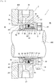
- FIG. 1 is a schematic cross-sectional view showing the configuration of the mechanical seal device according to the present embodiment.
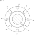
- FIG. 2 is a schematic view of a seal cover in the mechanical seal device according to the present embodiment when viewed in an axial direction.
- the mechanical seal device is used as a shaft seal device in a pump, a mixer, a joint, or a mill used in industrial fields such as, e.g., petroleum refining, chemistry, steel, medicine, and paper manufacturing.
- a target liquid to be sealed is a special liquid such as a high-temperature (200°C or higher) liquid which has a high solid content concentration.
- a high-temperature (200°C or higher) liquid which has a high solid content concentration.
- Specific examples thereof include asphalt, tar, and pitch (resin).
- a liquid which is not high in temperature and does not have a high solid content concentration is used.
- a mechanical seal device 1 is attached between a housing 200 as the casing of a pump or the like and a rotary shaft 300 which is inserted into a shaft hole 201 of the housing 200.
- the mechanical seal device is a cartridge-type mechanical seal device, and is configured by a seal cover 2 which is attached to the housing 200, and a sleeve 3 which is fit on the rotary shaft 300.
- a fixed ring 4 as a second annular member
- a bellows 5, a spring 6, and a retainer 8 are provided in the sleeve 3.
- a rotary ring 7 as a first annular member is provided.
- the seal cover 2 and the sleeve 3 are positioned by a set plate 10 attached to the outer peripheral surface of the sleeve 3, and are attached to the housing 200.
- the set plate 10 is fixed to the outer peripheral surface of the sleeve 3 with a socket bolt 11. The set plate 10 is detached when the assembly of the seal cover 2 and the sleeve 3 is ended.
- a sleeve collar 30 is attached to the outer peripheral surface of the end portion of the sleeve 3 on the side of the device outside B.
- the sleeve 3 is fixed to the rotary shaft 300 with a set screw 31 together with the sleeve collar 30, and rotates together with the rotary shaft 300.
- the sleeve collar 30 is prevented from rotating relative to the sleeve 3 by a knock pin 32, and rotates together with the rotary shaft 300.
- An O ring 33 is provided between the inner peripheral surface of the sleeve 3 and the outer peripheral surface of the rotary shaft 300, and a gap between them is sealed by the O ring 33.
- the rotary ring 7 is fit on the outer peripheral surface of the end portion of the sleeve 3 on the side of the device inside A.
- the rotary ring 7 has a concave portion 70 in a part of the inner peripheral side thereof, and a knock pin 34 attached to the sleeve 3 is fit in the concave portion 70.
- the rotary ring 7 is prevented from rotating relative to the sleeve 3 by the knock pin 34, and rotates together with the rotary shaft 300.
- an O ring 35 is provided between the inner peripheral surface of the rotary ring 7 and the outer peripheral surface of the sleeve 3, and a gap between them is sealed by the O ring 35.
- the side surface of the rotary ring 7 on the side of the device outside B serves as a slide surface 71, and the slide surface 71 comes into intimate contact with a slide surface 41 of the fixed ring 4 and slides relative to the slide surface 41 with the rotation of the rotary shaft 300.
- a super-hard material is used for the rotary ring 7, and examples of the super-hard material include silicon carbide, tungsten carbide, carbon, and other ceramics. However, the super-hard material is not limited thereto.
- a plurality of flushing passages 20 and drain holes 21 are provided at regular intervals along its outer peripheral surface. Only the flushing passage 20 which is required is used, and the flushing passage 20 which is not used is plugged with a plug.
- a plurality of fixing grooves 22 are provided at regular intervals in a circumferential direction. Bolts (not shown) are fit in the fixing grooves 22 and the seal cover 2 is thereby attached to the outer surface of the housing 200 (the end surface of the outer periphery of the opening portion of the shaft hole).
- a gasket 29 made of, e.g., a resin or metal material is provided between the seal cover 2 and the housing 200, and the gasket 29 seals a gap between them.
- the seal cover 2 has a support portion 23 in the shape of an inward flange which extends in a radially inward direction from the end portion on the side of the device outside B.
- a support portion 23 in the shape of an inward flange which extends in a radially inward direction from the end portion on the side of the device outside B.
- an annular concave portion 25 for holding one end of the bellows 5 and a concave portion 26 for holding the spring 6 are provided in the support portion 23, an annular concave portion 25 for holding one end of the bellows 5 and a concave portion 26 for holding the spring 6 are provided.
- a plurality of the concave portions 26 which are equal in number to the springs 6 are provided, and are disposed at regular intervals inside the concave portion 25 in the circumferential direction.
- a knock pin 27 for preventing the rotation of the retainer 8 is attached between the concave portions 26.
- the bellows 5 is a metal bellows which has an accordion-like bellows main body 50 and annular (tubular) holding portions 51 and 52 provided at both ends of the bellows main body 50.
- Examples of the material of the bellows 5 include alloys such as stainless steel, Inconel, Hastelloy, and Carpenter, and titanium, but the material thereof is not limited thereto.
- the present embodiment adopts a configuration capable of obtaining a biasing force (elastic force) of the spring 6, and hence the number of ridges of the bellows main body 50 can be set to about three to five (preferably four ridges) .
- the bellows 5 is attached between the support portion 23 and the fixed ring 4 of the seal cover 2. Specifically, the first holding portion 51 of the bellows 5 is fit in the annular concave portion 25 of the support portion 23 of the seal cover 2, and the second holding portion 52 thereof is assembled to the fixed ring 4 so as to abut on the fixed ring 4 in the axial direction.
- the bellows main body 50 of the bellows 5 is configured so as to be stretchable along the axial direction of the rotary shaft 300, and is assembled such that the biasing force which biases the fixed ring 4 toward the rotary ring 7 in the axial direction is exerted on the fixed ring 4.
- An O ring 24 is provided between the outer peripheral surface of the holding portion 51 and the outer peripheral surface of the concave portion 25 so as to be compressed in a radial direction
- an O ring 54 is provided between the tip surface of the holding portion 52 and the end surface of the fixed ring 4 so as to be compressed in the axial direction.
- the spring 6 is disposed at a position which is located on the inside of the first end portion 51 of the bellows 50 in the radial direction and substantially side by side with the bellows main body 5 in the axial direction.
- a plurality of the springs 6 are disposed in the circumferential direction.
- the number of the springs 6 is not particularly limited, and the number thereof can be set to 4 to 24.
- the spring 6 is assembled between the concave portion 26 of the support portion 23 and the retainer 8 of the seal cover 2 so as to be stretchable in the axial direction.
- the spring 6 is assembled such that the elastic force that biases the fixed ring 4 toward the rotary ring 7 in the axial direction is exerted on the fixed ring 4 via the retainer 8 and the second end portion 52 of the bellows 5.
- the retainer 8 has a tubular portion 80 and a flange portion 81 which extends in a radially outward direction from the end portion of the tubular portion 80 on the side of the device outside B.
- the retainer 8 is assembled to the inner side of the bellows 5, and the outer peripheral surface of the tubular portion 80 abuts on the inner peripheral surface of the second end portion 52 of the bellows 5 and the inner peripheral surface of the fixed ring 7.
- the flange portion 81 of the retainer 8 compresses the spring 6 in the axial direction and retains the spring 6 between the flange portion 81 and the concave portion 26 of the support portion 23 of the seal cover 2, and receives the biasing force from the spring 6 in the axial direction.
- a knock pin 82 is provided on the outer peripheral surface of the tubular portion 80 so as to protrude in the radially outward direction.
- the knock pin 82 is fit in a concave portion 53 provided on the inner peripheral side of the second end portion 52 of the bellows 5 and, with this, the bellows 5 is prevented from rotating relative to the retainer 8.
- a hole portion 28 is provided in the flange portion 81 of the retainer 8, and the knock pin 27 provided in the support portion 23 of the seal cover 2 is fit in the hole portion 28. With this, the retainer 8 is prevented from rotating relative to the seal cover 2.
- a convex portion 83 which protrudes in the radial direction is provided on the outer peripheral surface of the tubular portion 80.
- the convex portion 83 prevents relative movement of the retainer 8, the second end portion 52 of the bellows 5, and the fixed ring 4 in the axial direction, and allows integral movement thereof in the axial direction.
- the fixed ring 4 is fit on the outer periphery of the tip of the tubular portion 80 of the retainer 8 (the end portion on the side of the device inside A as a fixed end). In addition, the fixed ring 4 is assembled so as to abut on the tip surface of the second end portion 52 of the bellows 5 (the side surface on the side of the device inside A).
- a super-hard material is used for the fixed ring 4, and examples of the super-hard material include silicon carbide, tungsten carbide, carbon, and other ceramics. However, the super-hard material is not limited thereto.
- the fixed ring 4 has an annular convex portion 40 which protrudes from a surface opposing the rotary ring 7 toward the rotary ring 7.
- the annular slide surface 41 at the tip of the convex portion 40 comes into contact with the slide surface 71 of the rotary ring 7, and the annular seal surface S is thereby formed.
- the fixed ring 4 has a concave portion 42 in a part of the inner peripheral side thereof, a knock pin 55 attached to the second end portion 52 of the bellows 5 is fit in the concave portion 42, and the fixed ring 4 is prevented from rotating relative to the end portion 52. With this, a slide surface 40a rotates and slides relative to the slide surface 71 which rotates with the rotation of the rotary shaft 300.
- the surface of the fixed ring 4 opposite to the surface opposing the rotary ring 7 (the side surface on the side of the device outside B) abuts on the second end portion 52 of the bellows 5, and the fixed ring 4 receives the biasing force of the bellows 5 via the end portion 52 and receives the biasing force of the spring 6 via the retainer 8 and the end portion 52.
- the adhesion of the seal surface S to a relative positional fluctuation of the fixed ring 4 and the rotary ring 7 in the axial direction is increased.
- Examples of the material of the O rings 24, 33, 35, and 54 include nitrile rubber, EPDM, FKM, and FFKM. In the case where corrosion resistance is required, examples thereof include FFKM (Kalrez (registered trademark) or the like). However, the material is not limited thereto.
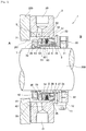
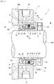
- FIGS. 3 and 4 are schematic cross-sectional views showing the configuration of a mechanical seal device according to a modification of the present embodiment.
- the integral configuration of the fixed ring 4, the bellows 5, and the retainer 8 is not limited to the configuration described in the above embodiment, and various configurations can be adopted.
- a concave portion 43 is provided on the inner peripheral side of the fixed ring 4, and a part of the knock pin 82 of the retainer 8 is fit in the above concave portion 43. A part of the knock pin 82 is also fit in the concave portion 53 of the second end portion 52 of the bellows 5. With this, the bellows 5 and the fixed ring 4 are prevented from rotating by the retainer 8.
- the configuration of preventing the rotation of the bellows 5 is not adopted. That is, the concave portion 53 provided in the second end portion 52 of the bellows 5 in the above embodiment is not provided in the present modification.
- the knock pin 82 of the retainer 8 is fit in the concave portion 43 provided on the inner peripheral side of the fixed ring 4, and the fixed ring 4 is prevented from rotating relative to the retainer 8.
- the rotation of the fixed ring 4 can be prevented in spite of the rotation of the rotary shaft 300, the propagation of the rotation to the bellows 5 is less likely to occur, and hence the bellows 5 scarcely rotates even when the configuration of preventing the rotation of the bellows 5 is not provided. Consequently, it is possible to simplify the configuration of the metal bellows 5 which requires high manufacturing cost and reduce the cost.
- the mechanical seal device 1 has the configuration in which the bellows 5 and the spring 6 are substantially arranged in the axial direction of the rotary shaft 300. That is, unlike the conventional art, the mechanical seal device 1 has the configuration in which the bellows 5 and the spring 6 are not arranged in the radial direction. With this, it is possible to make the radial dimensions of the entire device more compact than in the conventional art. Consequently, in the cartridge-type mechanical seal device, it is possible to relieve restrictions on the attachment space and increase the range of devices to which the cartridge-type mechanical seal device can be attached.
- the mechanical seal device 1 is configured such that the outer side of the bellows 5 in the radial direction is on the side of the device inside A as the side of a target region to be sealed. That is, the target liquid to be sealed is sealed on the outside of the bellows 5.
- the slurry is not deposited in the groove of the bellows 5. Consequently, an effect on the stretchability of the bellows 5 resulting from the deposition of the slurry or the like seen in the conventional art does not occur, and it is possible to maintain performance in long-term use.
- the spring 6 is disposed on the side of the device outside B. Consequently, an effect on performance resulting from corrosion caused by the target liquid to be sealed, deposition of the slurry or the like which is similar to that in the bellows 5, or clogging therewith does not occur, and it is possible to maintain the performance in long-term use.
Landscapes
- Engineering & Computer Science (AREA)
- General Engineering & Computer Science (AREA)
- Mechanical Engineering (AREA)
- Mechanical Sealing (AREA)
Abstract
Description
- The present invention relates to a mechanical seal device.
- Conventionally, as a mechanical seal device for sealing a special liquid such as a chemical which dose not allow the use of a special high-temperature pump or an O ring, there is known a mechanical seal device which includes a metal bellows. In addition, there is known a mechanical seal device which is configured as a cartridge-type mechanical seal device in order to improve assembly and make the mechanical seal device compact (
Patent Documents 1 and 2). - With reference to
FIG. 5 , a conventional cartridge-type mechanical seal device will be described.FIG. 5 is a schematic cross-sectional view for explaining the configuration of a mechanical seal device according to the conventional art. - A
mechanical seal device 100 shown inFIG. 5 is provided between ahousing 200 such as the casing of a pump or the like and arotary shaft 300, and seals the inside A of thehousing 200 from the outside (air side) B. Themechanical seal device 100 has aseal cover 102 which is attached to thehousing 200 and asleeve 103 which is fit on therotary shaft 300. In theseal cover 102, afixed ring 104 as an annular member, abellows 105, and aspring 106 are provided. In thesleeve 103, arotary ring 107 as an annular member is provided. - The
seal cover 102 and thesleeve 103 are attached to thehousing 200 and therotary shaft 300 respectively such that the fixedring 104 and therotary ring 107 are in contact with each other. Thefixed ring 104 and therotary ring 107 are slidably in contact with each other to form an annular seal surface S, and the seal state is thereby formed. Thebellows 105 and thespring 106 are provided so as to be stretchable in an axial direction, and bias the fixedring 104 toward therotary ring 107 to thereby enhance the adhesion of the seal surface S. - Herein, in the cartridge-type
mechanical seal device 100 described above, its cost is reduced and the cartridge-type mechanical seal device is made compact by reducing the number of ridges of themetal bellows 105 which requires high manufacturing cost, and an insufficient biasing force is supplemented by using thespring 106. In addition, thespring 106 is disposed on the outer peripheral side of thebellows 105 in order to avoid exposure to a liquid. - However, in the above cartridge configuration in which the
bellows 105 and thespring 106 are arranged in a radial direction, a reduction in radial dimensions is limited, and hence attachment space is restricted and the range of devices to which the mechanical seal device can be applied is limited. In addition, slurry having a high density contained in a target liquid to be sealed is pushed outward by a centrifugal force caused by the rotation of therotary shaft 300, and is pushed into a groove between the ridges on the inner peripheral side of thebellows 105. When the mechanical seal device is used for a long time period, there is a possibility that the slurry deposited in the groove affects stretchability of thebellows 105. -
- [Patent Document 1]
WO 2010/004809 - [Patent Document 2]
WO 2010/123025 - An object of the present invention is to provide the mechanical seal device capable of increasing the application range and maintaining performance in long-term use.
- In order to achieve the above object, the mechanical seal device in the present invention is a mechanical seal device which seals space between a shaft hole provided in a housing and a rotary shaft inserted into the shaft hole and hence seals a liquid in the housing including a first annular member which is fixed to the rotary shaft, a second annular member which is slidably in contact with the first annular member and forms an annular seal surface, a bellows which supports the second annular member so as to bias the second annular member toward the first annular member, a biasing member which biases the second annular member toward the first annular member, and a seal cover which is attached to the housing, supports the bellows such that an outer peripheral surface of the bellows is on the inside of the housing relative to the seal surface, and supports the biasing member at a position located on the outside of the housing relative to the seal surface and side by side with the bellows in an axial direction of the rotary shaft.
- According to the present invention, the bellow and the biasing member are not arranged in a radial direction, and hence it is possible to make radial dimensions of the device compact. In addition, a target liquid to be sealed is sealed on the outer peripheral side of the bellows, and hence slurry or the like in the target liquid to be sealed is not deposited in a groove of the bellows.
- The mechanical seal device preferably further includes a retainer which has a tubular portion fixed to the second annular member and extending from the fixed end in the axial direction on an inner peripheral side of the bellows and a flange portion extending from an end portion opposite to the fixed end of the tubular portion in a radially outward direction and receiving a biasing force of the biasing member.
- By providing the retainer described above, it is possible to easily implement a configuration in which the target liquid to be sealed is sealed on the outer peripheral side of the bellows, and the bellows and the biasing member are arranged in the axial direction.
- According to the present invention, it is possible to increase the application range and maintain the performance in long-term use.
-
-
FIG. 1 is a schematic cross-sectional view of a mechanical seal device according to an embodiment of the present invention; -
FIG. 2 is a schematic view of a seal cover when viewed in an axial direction; -
FIG. 3 is a schematic cross-sectional view of a mechanical seal device according to a first modification of the present invention; -
FIG. 4 is a schematic cross-sectional view of a mechanical seal device according to a second modification of the present invention; and -
FIG. 5 is a schematic cross-sectional view of a mechanical seal device according to the conventional art. - Hereinbelow, with reference to the drawings, the best mode for carrying out the invention will be illustratively described in detail based on an embodiment. However, the scope of the present invention is not limited only to dimensions, materials, shapes, and relative arrangements of constituent parts described in the embodiment unless specifically described.
- With reference to
FIGS. 1 and2 , a mechanical seal device according to the embodiment of the present invention will be described.FIG. 1 is a schematic cross-sectional view showing the configuration of the mechanical seal device according to the present embodiment.FIG. 2 is a schematic view of a seal cover in the mechanical seal device according to the present embodiment when viewed in an axial direction. - The mechanical seal device according to the present embodiment is used as a shaft seal device in a pump, a mixer, a joint, or a mill used in industrial fields such as, e.g., petroleum refining, chemistry, steel, medicine, and paper manufacturing. In the case where the mechanical seal device is used particularly in petroleum refining, a petrochemical plant, and a chemical-related plant, it is often the case that a target liquid to be sealed is a special liquid such as a high-temperature (200°C or higher) liquid which has a high solid content concentration. Specific examples thereof include asphalt, tar, and pitch (resin). However, there are cases where a liquid which is not high in temperature and does not have a high solid content concentration is used.
- As shown in
FIG. 1 , amechanical seal device 1 according to the present embodiment is attached between ahousing 200 as the casing of a pump or the like and arotary shaft 300 which is inserted into ashaft hole 201 of thehousing 200. By the mechanical seal device, the inside A of thehousing 200 as a device inside is sealed from the outside (air side) B as a device outside. Themechanical seal device 1 is a cartridge-type mechanical seal device, and is configured by aseal cover 2 which is attached to thehousing 200, and asleeve 3 which is fit on therotary shaft 300. In theseal cover 2, afixed ring 4 as a second annular member, abellows 5, aspring 6, and aretainer 8 are provided. In thesleeve 3, arotary ring 7 as a first annular member is provided. - The
seal cover 2 and thesleeve 3 are positioned by aset plate 10 attached to the outer peripheral surface of thesleeve 3, and are attached to thehousing 200. Theset plate 10 is fixed to the outer peripheral surface of thesleeve 3 with asocket bolt 11. Theset plate 10 is detached when the assembly of theseal cover 2 and thesleeve 3 is ended. - A
sleeve collar 30 is attached to the outer peripheral surface of the end portion of thesleeve 3 on the side of the device outside B. Thesleeve 3 is fixed to therotary shaft 300 with aset screw 31 together with thesleeve collar 30, and rotates together with therotary shaft 300. Thesleeve collar 30 is prevented from rotating relative to thesleeve 3 by aknock pin 32, and rotates together with therotary shaft 300. AnO ring 33 is provided between the inner peripheral surface of thesleeve 3 and the outer peripheral surface of therotary shaft 300, and a gap between them is sealed by theO ring 33. Therotary ring 7 is fit on the outer peripheral surface of the end portion of thesleeve 3 on the side of the device inside A. - The
rotary ring 7 has aconcave portion 70 in a part of the inner peripheral side thereof, and aknock pin 34 attached to thesleeve 3 is fit in theconcave portion 70. Therotary ring 7 is prevented from rotating relative to thesleeve 3 by theknock pin 34, and rotates together with therotary shaft 300. In addition, anO ring 35 is provided between the inner peripheral surface of therotary ring 7 and the outer peripheral surface of thesleeve 3, and a gap between them is sealed by theO ring 35. - The side surface of the
rotary ring 7 on the side of the device outside B serves as aslide surface 71, and theslide surface 71 comes into intimate contact with aslide surface 41 of the fixedring 4 and slides relative to theslide surface 41 with the rotation of therotary shaft 300. A super-hard material is used for therotary ring 7, and examples of the super-hard material include silicon carbide, tungsten carbide, carbon, and other ceramics. However, the super-hard material is not limited thereto. - As shown in
FIG. 2 , in theseal cover 2, a plurality of flushingpassages 20 and drain holes 21 are provided at regular intervals along its outer peripheral surface. Only theflushing passage 20 which is required is used, and theflushing passage 20 which is not used is plugged with a plug. In addition, in theseal cover 2, a plurality of fixinggrooves 22 are provided at regular intervals in a circumferential direction. Bolts (not shown) are fit in the fixinggrooves 22 and theseal cover 2 is thereby attached to the outer surface of the housing 200 (the end surface of the outer periphery of the opening portion of the shaft hole). - Further, as shown in
FIG. 1 , agasket 29 made of, e.g., a resin or metal material is provided between theseal cover 2 and thehousing 200, and thegasket 29 seals a gap between them. - As shown in
FIG. 1 , theseal cover 2 has asupport portion 23 in the shape of an inward flange which extends in a radially inward direction from the end portion on the side of the device outside B. In thesupport portion 23, an annularconcave portion 25 for holding one end of thebellows 5 and aconcave portion 26 for holding thespring 6 are provided. A plurality of theconcave portions 26 which are equal in number to thesprings 6 are provided, and are disposed at regular intervals inside theconcave portion 25 in the circumferential direction. Aknock pin 27 for preventing the rotation of theretainer 8 is attached between theconcave portions 26. - The
bellows 5 is a metal bellows which has an accordion-like bellowsmain body 50 and annular (tubular) holdingportions main body 50. Examples of the material of thebellows 5 include alloys such as stainless steel, Inconel, Hastelloy, and Carpenter, and titanium, but the material thereof is not limited thereto. The present embodiment adopts a configuration capable of obtaining a biasing force (elastic force) of thespring 6, and hence the number of ridges of the bellowsmain body 50 can be set to about three to five (preferably four ridges) . - The
bellows 5 is attached between thesupport portion 23 and the fixedring 4 of theseal cover 2. Specifically, the first holdingportion 51 of thebellows 5 is fit in the annularconcave portion 25 of thesupport portion 23 of theseal cover 2, and the second holdingportion 52 thereof is assembled to the fixedring 4 so as to abut on the fixedring 4 in the axial direction. In addition, the bellowsmain body 50 of thebellows 5 is configured so as to be stretchable along the axial direction of therotary shaft 300, and is assembled such that the biasing force which biases the fixedring 4 toward therotary ring 7 in the axial direction is exerted on the fixedring 4. AnO ring 24 is provided between the outer peripheral surface of the holdingportion 51 and the outer peripheral surface of theconcave portion 25 so as to be compressed in a radial direction, and anO ring 54 is provided between the tip surface of the holdingportion 52 and the end surface of the fixedring 4 so as to be compressed in the axial direction. - The
spring 6 is disposed at a position which is located on the inside of thefirst end portion 51 of thebellows 50 in the radial direction and substantially side by side with the bellowsmain body 5 in the axial direction. A plurality of thesprings 6 are disposed in the circumferential direction. The number of thesprings 6 is not particularly limited, and the number thereof can be set to 4 to 24. Thespring 6 is assembled between theconcave portion 26 of thesupport portion 23 and theretainer 8 of theseal cover 2 so as to be stretchable in the axial direction. Thespring 6 is assembled such that the elastic force that biases the fixedring 4 toward therotary ring 7 in the axial direction is exerted on the fixedring 4 via theretainer 8 and thesecond end portion 52 of thebellows 5. - The
retainer 8 has atubular portion 80 and aflange portion 81 which extends in a radially outward direction from the end portion of thetubular portion 80 on the side of the device outside B. Theretainer 8 is assembled to the inner side of thebellows 5, and the outer peripheral surface of thetubular portion 80 abuts on the inner peripheral surface of thesecond end portion 52 of thebellows 5 and the inner peripheral surface of the fixedring 7. In addition, theflange portion 81 of theretainer 8 compresses thespring 6 in the axial direction and retains thespring 6 between theflange portion 81 and theconcave portion 26 of thesupport portion 23 of theseal cover 2, and receives the biasing force from thespring 6 in the axial direction. - In the
retainer 8, aknock pin 82 is provided on the outer peripheral surface of thetubular portion 80 so as to protrude in the radially outward direction. Theknock pin 82 is fit in aconcave portion 53 provided on the inner peripheral side of thesecond end portion 52 of thebellows 5 and, with this, thebellows 5 is prevented from rotating relative to theretainer 8. In addition, ahole portion 28 is provided in theflange portion 81 of theretainer 8, and theknock pin 27 provided in thesupport portion 23 of theseal cover 2 is fit in thehole portion 28. With this, theretainer 8 is prevented from rotating relative to theseal cover 2. - In addition, in the
retainer 8, aconvex portion 83 which protrudes in the radial direction is provided on the outer peripheral surface of thetubular portion 80. Theconvex portion 83 prevents relative movement of theretainer 8, thesecond end portion 52 of thebellows 5, and the fixedring 4 in the axial direction, and allows integral movement thereof in the axial direction. - The fixed
ring 4 is fit on the outer periphery of the tip of thetubular portion 80 of the retainer 8 (the end portion on the side of the device inside A as a fixed end). In addition, the fixedring 4 is assembled so as to abut on the tip surface of thesecond end portion 52 of the bellows 5 (the side surface on the side of the device inside A). A super-hard material is used for the fixedring 4, and examples of the super-hard material include silicon carbide, tungsten carbide, carbon, and other ceramics. However, the super-hard material is not limited thereto. - The fixed
ring 4 has an annularconvex portion 40 which protrudes from a surface opposing therotary ring 7 toward therotary ring 7. Theannular slide surface 41 at the tip of theconvex portion 40 comes into contact with theslide surface 71 of therotary ring 7, and the annular seal surface S is thereby formed. In addition, the fixedring 4 has aconcave portion 42 in a part of the inner peripheral side thereof, aknock pin 55 attached to thesecond end portion 52 of thebellows 5 is fit in theconcave portion 42, and the fixedring 4 is prevented from rotating relative to theend portion 52. With this, a slide surface 40a rotates and slides relative to theslide surface 71 which rotates with the rotation of therotary shaft 300. - The surface of the fixed
ring 4 opposite to the surface opposing the rotary ring 7 (the side surface on the side of the device outside B) abuts on thesecond end portion 52 of thebellows 5, and the fixedring 4 receives the biasing force of thebellows 5 via theend portion 52 and receives the biasing force of thespring 6 via theretainer 8 and theend portion 52. With this, the adhesion of the seal surface S to a relative positional fluctuation of the fixedring 4 and therotary ring 7 in the axial direction is increased. - Examples of the material of the O rings 24, 33, 35, and 54 include nitrile rubber, EPDM, FKM, and FFKM. In the case where corrosion resistance is required, examples thereof include FFKM (Kalrez (registered trademark) or the like). However, the material is not limited thereto.
- Each of
FIGS. 3 and4 is a schematic cross-sectional view showing the configuration of a mechanical seal device according to a modification of the present embodiment. The integral configuration of the fixedring 4, thebellows 5, and theretainer 8 is not limited to the configuration described in the above embodiment, and various configurations can be adopted. - In a first modification shown in
FIG. 3 , aconcave portion 43 is provided on the inner peripheral side of the fixedring 4, and a part of theknock pin 82 of theretainer 8 is fit in the aboveconcave portion 43. A part of theknock pin 82 is also fit in theconcave portion 53 of thesecond end portion 52 of thebellows 5. With this, thebellows 5 and the fixedring 4 are prevented from rotating by theretainer 8. - In a second modification shown in
FIG. 4 , the configuration of preventing the rotation of thebellows 5 is not adopted. That is, theconcave portion 53 provided in thesecond end portion 52 of thebellows 5 in the above embodiment is not provided in the present modification. Theknock pin 82 of theretainer 8 is fit in theconcave portion 43 provided on the inner peripheral side of the fixedring 4, and the fixedring 4 is prevented from rotating relative to theretainer 8. When the rotation of the fixedring 4 can be prevented in spite of the rotation of therotary shaft 300, the propagation of the rotation to thebellows 5 is less likely to occur, and hence thebellows 5 scarcely rotates even when the configuration of preventing the rotation of thebellows 5 is not provided. Consequently, it is possible to simplify the configuration of the metal bellows 5 which requires high manufacturing cost and reduce the cost. - The
mechanical seal device 1 according to the present embodiment has the configuration in which thebellows 5 and thespring 6 are substantially arranged in the axial direction of therotary shaft 300. That is, unlike the conventional art, themechanical seal device 1 has the configuration in which thebellows 5 and thespring 6 are not arranged in the radial direction. With this, it is possible to make the radial dimensions of the entire device more compact than in the conventional art. Consequently, in the cartridge-type mechanical seal device, it is possible to relieve restrictions on the attachment space and increase the range of devices to which the cartridge-type mechanical seal device can be attached. - In addition, the
mechanical seal device 1 according to the present embodiment is configured such that the outer side of thebellows 5 in the radial direction is on the side of the device inside A as the side of a target region to be sealed. That is, the target liquid to be sealed is sealed on the outside of thebellows 5. With this, even when slurry or the like contained in the target liquid to be sealed is moved outward by the centrifugal force caused by the rotation of therotary shaft 300, unlike the conventional art, the slurry is not deposited in the groove of thebellows 5. Consequently, an effect on the stretchability of thebellows 5 resulting from the deposition of the slurry or the like seen in the conventional art does not occur, and it is possible to maintain performance in long-term use. - Further, in the
mechanical seal device 1 according to the present embodiment, thespring 6 is disposed on the side of the device outside B. Consequently, an effect on performance resulting from corrosion caused by the target liquid to be sealed, deposition of the slurry or the like which is similar to that in thebellows 5, or clogging therewith does not occur, and it is possible to maintain the performance in long-term use. -
- 1
- mechanical seal device
- 200
- housing
- 300
- rotary shaft
- 2
- seal cover
- 3
- sleeve
- 4
- fixed ring
- 5
- bellows
- 6
- spring
- 7
- rotary ring
- 8
- retainer
Claims (2)
- A mechanical seal device which seals space between a shaft hole provided in a housing and a rotary shaft inserted into the shaft hole and hence seals a liquid in the housing, comprising:a first annular member which is fixed to the rotary shaft;a second annular member which is slidably in contact with the first annular member and forms an annular seal surface;a bellows which supports the second annular member so as to bias the second annular member toward the first annular member;a biasing member which biases the second annular member toward the first annular member; anda seal cover which is attached to the housing, supports the bellows such that an outer peripheral surface of the bellows is on the inside of the housing relative to the seal surface, and supports the biasing member at a position located on the outside of the housing relative to the seal surface and side by side with the bellows in an axial direction of the rotary shaft.
- The mechanical seal device according to claim 1, further comprising: a retainer which has a tubular portion fixed to the second annular member and extending from the fixed end in the axial direction on an inner peripheral side of the bellows; and a flange portion extending from an end portion opposite to the fixed end of the tubular portion in a radially outward direction and receiving a biasing force of the biasing member.
Applications Claiming Priority (2)
| Application Number | Priority Date | Filing Date | Title |
|---|---|---|---|
| JP2013111134 | 2013-05-27 | ||
| PCT/JP2014/064005 WO2014192761A1 (en) | 2013-05-27 | 2014-05-27 | Mechanical seal device |
Publications (2)
| Publication Number | Publication Date |
|---|---|
| EP3006789A1 true EP3006789A1 (en) | 2016-04-13 |
| EP3006789A4 EP3006789A4 (en) | 2017-01-04 |
Family
ID=51988789
Family Applications (1)
| Application Number | Title | Priority Date | Filing Date |
|---|---|---|---|
| EP14803504.1A Withdrawn EP3006789A4 (en) | 2013-05-27 | 2014-05-27 | Mechanical seal device |
Country Status (5)
| Country | Link |
|---|---|
| US (1) | US9400054B2 (en) |
| EP (1) | EP3006789A4 (en) |
| JP (1) | JPWO2014192761A1 (en) |
| CN (1) | CN104995440A (en) |
| WO (1) | WO2014192761A1 (en) |
Cited By (1)
| Publication number | Priority date | Publication date | Assignee | Title |
|---|---|---|---|---|
| CN106512479A (en) * | 2016-12-15 | 2017-03-22 | 苏州楚博生物技术有限公司 | Vacuum type sealing structure for chromatographic column |
Families Citing this family (12)
| Publication number | Priority date | Publication date | Assignee | Title |
|---|---|---|---|---|
| EP2886914A4 (en) * | 2012-08-22 | 2016-07-27 | Eagle Ind Co Ltd | Double mechanical seal device |
| WO2015190350A1 (en) * | 2014-06-13 | 2015-12-17 | イーグル工業株式会社 | Mechanical seal |
| BR112017004942A2 (en) * | 2014-09-30 | 2017-12-05 | Siemens Ag | electric machine, and method for operating an electric machine. |
| US10274008B2 (en) * | 2015-06-19 | 2019-04-30 | Steering Solutions Ip Holding Corporation | Axial load bearing assembly |
| DE102016200818B4 (en) * | 2016-01-21 | 2020-09-10 | Eagleburgmann Germany Gmbh & Co. Kg | Mechanical seal arrangement with reduced leakage |
| CN109073090B (en) * | 2016-04-27 | 2020-10-30 | 伊格尔工业股份有限公司 | mechanical seal |
| CN113586722B (en) * | 2016-07-12 | 2024-02-13 | 约翰起重机有限公司 | Non-foldable flexible sealing diaphragms and sealing assemblies for rotating shaft equipment |
| US11473680B2 (en) | 2016-07-12 | 2022-10-18 | John Crane Inc. | Non-collapsible flexible sealing membrane and seal assembly for rotary shaft equipment |
| JP2018189118A (en) * | 2017-04-28 | 2018-11-29 | 株式会社荏原製作所 | Shaft seal device cover |
| CN109751277B (en) * | 2019-02-27 | 2024-02-13 | 沈阳北碳密封有限公司 | Positive and negative pressure working condition mechanical seal for self-priming pump |
| CN111927631A (en) * | 2020-07-31 | 2020-11-13 | 中国航发贵阳发动机设计研究所 | Graphite sealing device for sealing lubricating oil cavity of aircraft engine |
| JP2024067949A (en) * | 2022-11-07 | 2024-05-17 | イーグルブルグマンジャパン株式会社 | mechanical seal |
Family Cites Families (14)
| Publication number | Priority date | Publication date | Assignee | Title |
|---|---|---|---|---|
| US2574808A (en) * | 1946-10-04 | 1951-11-13 | Chrysler Corp | Squeak inhibiting seal construction for fluid power transmitting devices |
| CH512850A (en) * | 1970-01-07 | 1971-09-15 | Bbc Brown Boveri & Cie | Device for preventing dust from entering between the rotor and stator of an electric motor |
| DE2703104C2 (en) * | 1977-01-26 | 1982-07-15 | Kaco Gmbh + Co, 7100 Heilbronn | Mechanical seal |
| US4275889A (en) * | 1978-04-06 | 1981-06-30 | Cummins Engine Company, Inc. | Seal construction |
| DE3927589C2 (en) * | 1989-08-22 | 1994-09-29 | Kaco Gmbh Co | Sealing unit |
| CN2176466Y (en) * | 1993-04-28 | 1994-09-07 | 石富江 | Mechanical sealing unit of metal bellows with springs |
| DE19637814A1 (en) * | 1996-09-17 | 1998-04-02 | Freudenberg Carl Fa | Mechanical seal |
| DE19637813C2 (en) * | 1996-09-17 | 2001-12-06 | Freudenberg Carl Fa | Mechanical seal |
| CN100513833C (en) * | 2006-09-18 | 2009-07-15 | 丹东克隆集团有限责任公司 | Anticlogging mechanical sealing device |
| US20110037232A1 (en) | 2008-07-07 | 2011-02-17 | Eagle Industry Co., Ltd. | Mechanical seal device |
| CN201368204Y (en) * | 2009-03-24 | 2009-12-23 | 宁波东联密封件有限公司 | Corrugated tube mechanical seal |
| WO2010123025A1 (en) | 2009-04-23 | 2010-10-28 | イーグル工業株式会社 | Mechanical seal device |
| WO2011007765A1 (en) * | 2009-07-16 | 2011-01-20 | イーグル工業株式会社 | Mechanical sealing device |
| CN202280843U (en) * | 2011-10-17 | 2012-06-20 | 江苏华青流体科技有限公司 | Corrugated pipe sealing device |
-
2014
- 2014-05-27 JP JP2015519878A patent/JPWO2014192761A1/en not_active Withdrawn
- 2014-05-27 WO PCT/JP2014/064005 patent/WO2014192761A1/en not_active Ceased
- 2014-05-27 EP EP14803504.1A patent/EP3006789A4/en not_active Withdrawn
- 2014-05-27 US US14/770,535 patent/US9400054B2/en not_active Expired - Fee Related
- 2014-05-27 CN CN201480008670.6A patent/CN104995440A/en active Pending
Cited By (2)
| Publication number | Priority date | Publication date | Assignee | Title |
|---|---|---|---|---|
| CN106512479A (en) * | 2016-12-15 | 2017-03-22 | 苏州楚博生物技术有限公司 | Vacuum type sealing structure for chromatographic column |
| CN106512479B (en) * | 2016-12-15 | 2018-12-28 | 苏州楚博生物技术有限公司 | Vacuum type sealing structure for chromatographic column |
Also Published As
| Publication number | Publication date |
|---|---|
| US9400054B2 (en) | 2016-07-26 |
| CN104995440A (en) | 2015-10-21 |
| JPWO2014192761A1 (en) | 2017-02-23 |
| WO2014192761A1 (en) | 2014-12-04 |
| EP3006789A4 (en) | 2017-01-04 |
| US20160003362A1 (en) | 2016-01-07 |
Similar Documents
| Publication | Publication Date | Title |
|---|---|---|
| US9400054B2 (en) | Mechanical seal device | |
| JP5514107B2 (en) | Mechanical seal device | |
| JP5593519B2 (en) | Piping connection mechanism for seal device and mechanical seal device | |
| EP3450805B1 (en) | Mechanical seal | |
| JP5615267B2 (en) | Mechanical seal device | |
| CN104220769B (en) | Rotary chuck seal with internal face sealing surface | |
| CN102369375A (en) | Mechanical seal device | |
| EP3070379B1 (en) | Mechanical seal | |
| US20190107204A1 (en) | Seal Assembly with Eccentricity Tracking | |
| EP3686464B1 (en) | Mecanical seal | |
| EP2896854B1 (en) | Mechanical seal | |
| CN114151545A (en) | Cassette seal for use in extreme environments | |
| JP5703135B2 (en) | Shaft seal device for vertical axis | |
| CN106537004B (en) | Sealing device | |
| US9027928B2 (en) | Pumping seal having projections for axially positioning a biasing member | |
| CN111503298B (en) | Sealing structure of valve body and valve seat and gate valve | |
| CN104662315B (en) | Sealing ring and sealing cartridge with such a sealing ring | |
| JP5415980B2 (en) | Mechanical seal device | |
| GB2331131A (en) | Shaft seal with secondary lip seal | |
| JP6309839B2 (en) | mechanical seal | |
| JP2010261573A (en) | Corrosion-resistant bellows type mechanical seal | |
| JP2019203564A (en) | Sealing device |
Legal Events
| Date | Code | Title | Description |
|---|---|---|---|
| PUAI | Public reference made under article 153(3) epc to a published international application that has entered the european phase |
Free format text: ORIGINAL CODE: 0009012 |
|
| 17P | Request for examination filed |
Effective date: 20150818 |
|
| AK | Designated contracting states |
Kind code of ref document: A1 Designated state(s): AL AT BE BG CH CY CZ DE DK EE ES FI FR GB GR HR HU IE IS IT LI LT LU LV MC MK MT NL NO PL PT RO RS SE SI SK SM TR |
|
| AX | Request for extension of the european patent |
Extension state: BA ME |
|
| DAX | Request for extension of the european patent (deleted) | ||
| A4 | Supplementary search report drawn up and despatched |
Effective date: 20161207 |
|
| RIC1 | Information provided on ipc code assigned before grant |
Ipc: F16J 15/36 20060101AFI20161201BHEP Ipc: F16J 15/34 20060101ALI20161201BHEP |
|
| STAA | Information on the status of an ep patent application or granted ep patent |
Free format text: STATUS: REQUEST FOR EXAMINATION WAS MADE |
|
| STAA | Information on the status of an ep patent application or granted ep patent |
Free format text: STATUS: THE APPLICATION IS DEEMED TO BE WITHDRAWN |
|
| 18D | Application deemed to be withdrawn |
Effective date: 20170704 |